EP0312918A2 - Procédé et appareil de fabrication d'un corps de boîte à section non circulaire - Google Patents
Procédé et appareil de fabrication d'un corps de boîte à section non circulaire Download PDFInfo
- Publication number
- EP0312918A2 EP0312918A2 EP88117073A EP88117073A EP0312918A2 EP 0312918 A2 EP0312918 A2 EP 0312918A2 EP 88117073 A EP88117073 A EP 88117073A EP 88117073 A EP88117073 A EP 88117073A EP 0312918 A2 EP0312918 A2 EP 0312918A2
- Authority
- EP
- European Patent Office
- Prior art keywords
- section
- bodies
- edges
- blank
- bending
- Prior art date
- Legal status (The legal status is an assumption and is not a legal conclusion. Google has not performed a legal analysis and makes no representation as to the accuracy of the status listed.)
- Granted
Links
- 238000000034 method Methods 0.000 title claims description 23
- 238000005452 bending Methods 0.000 claims abstract description 32
- 238000003466 welding Methods 0.000 claims abstract description 31
- 238000003825 pressing Methods 0.000 claims abstract description 19
- 238000004519 manufacturing process Methods 0.000 claims description 29
- 238000005520 cutting process Methods 0.000 claims description 7
- 239000011324 bead Substances 0.000 claims description 6
- 239000000463 material Substances 0.000 claims description 5
- 238000011143 downstream manufacturing Methods 0.000 claims 1
- 238000005476 soldering Methods 0.000 description 7
- 239000000853 adhesive Substances 0.000 description 2
- 230000001070 adhesive effect Effects 0.000 description 2
- 230000006835 compression Effects 0.000 description 2
- 238000007906 compression Methods 0.000 description 2
- 230000001419 dependent effect Effects 0.000 description 2
- 241000237942 Conidae Species 0.000 description 1
- 235000015278 beef Nutrition 0.000 description 1
- 230000009172 bursting Effects 0.000 description 1
- 238000004049 embossing Methods 0.000 description 1
- 239000003344 environmental pollutant Substances 0.000 description 1
- 235000013305 food Nutrition 0.000 description 1
- 238000007373 indentation Methods 0.000 description 1
- 238000000465 moulding Methods 0.000 description 1
- 231100000719 pollutant Toxicity 0.000 description 1
- 238000002360 preparation method Methods 0.000 description 1
Images


Classifications
-
- B—PERFORMING OPERATIONS; TRANSPORTING
- B21—MECHANICAL METAL-WORKING WITHOUT ESSENTIALLY REMOVING MATERIAL; PUNCHING METAL
- B21D—WORKING OR PROCESSING OF SHEET METAL OR METAL TUBES, RODS OR PROFILES WITHOUT ESSENTIALLY REMOVING MATERIAL; PUNCHING METAL
- B21D51/00—Making hollow objects
- B21D51/16—Making hollow objects characterised by the use of the objects
- B21D51/26—Making hollow objects characterised by the use of the objects cans or tins; Closing same in a permanent manner
- B21D51/2646—Of particular non cylindrical shape, e.g. conical, rectangular, polygonal, bulged
-
- B—PERFORMING OPERATIONS; TRANSPORTING
- B21—MECHANICAL METAL-WORKING WITHOUT ESSENTIALLY REMOVING MATERIAL; PUNCHING METAL
- B21D—WORKING OR PROCESSING OF SHEET METAL OR METAL TUBES, RODS OR PROFILES WITHOUT ESSENTIALLY REMOVING MATERIAL; PUNCHING METAL
- B21D51/00—Making hollow objects
- B21D51/16—Making hollow objects characterised by the use of the objects
- B21D51/26—Making hollow objects characterised by the use of the objects cans or tins; Closing same in a permanent manner
- B21D51/2676—Cans or tins having longitudinal or helical seams
Definitions
- the invention relates to a method for producing can bodies having a non-circular cross section from flat blanks, the mutually opposite blank edges of which are connected in a longitudinal seam.
- the invention further relates to a device for performing the method.
- Resistance roller seam welding machines are known for the production of can bodies from flat blanks, which, in addition to the device for welding, have a rounding device for deforming the blanks and enable can bodies to be produced in very high quantities per minute, but these known machines are only for the production of cylindrical can bodies suitable.
- Cans with a non-circular cross-section, especially those with a rectangular cross-section, which are also available on the market on a large scale, for the reception of foodstuffs have hitherto mainly been produced using a soldering process, the can bodies formed from flat blanks being transported through a soldering bath will.
- soldering material consists mostly of lead and should therefore not come into contact with food, which is why one is sharpened today in the awareness of an environment less polluted by pollutants is very keen to replace the soldering process for the can production with another production method.
- cans with a rectangular cross-section that have been manufactured using the soldering process have been known for a long time. They taper upwards and, because of this shape, let consumers recognize that a certain content such as beef is contained in these cans in a special preparation. Of course you want to keep this box shape with the function like a trademark, but you can do without the soldering process, which was not possible until now.
- such cans are also provided with a tear strip delimited by lines scratched all around, which has a tear tab at one end, so that the can can be easily opened without special tools.
- the tear tab protrudes from an edge of the flat blank from which the can is made, and because of this tear tab the manufacture of such a can is made even more difficult if it is not to be produced using the known soldering process.
- the blanks are exactly rectangular, while for a conical can body, blanks in the form of the development of a truncated cone shell are required, in which two opposite edges are curved.
- the shape of the cut is similar to the aforementioned development of a truncated cone jacket, but with straight sections on the two edges. After being deformed into a can body, such a cut results in one without internal stress, and it can also be easily concluded from the difference in the cut shape that an initially cylindrical can body can only be forced into a rectangular and additionally conical shape with great effort .
- the object underlying the present invention was therefore to produce can bodies from flat blanks which do not have a round cross section and preferably have a rectangular cross section with rounded corners, but can also be triangular in cross section or with more than four corners. Furthermore, the task also consisted in producing can bodies of this type and with a cross section, the size of which continuously changes over the length of the can body, i.e. To produce a can body with a taper that makes emptying the can particularly easy.
- the task also consisted in producing can bodies of this type and additionally with a tear strip, electrical resistance welding with the aid of a resistance roller seam welding device preferably being used for connecting the cut edges, but also an adhesive process or laser welding can be used.
- the measures according to claim 1 serve to solve the basic task.
- Special features of the production process result from the dependent claims.
- the device for carrying out the manufacturing process has the features according to claim 6 and has features according to the following dependent claims for special features of the can bodies to be manufactured.
- the advantages of the new method and the device are that can bodies with a large number of pieces per time and specially shaped can bodies can be produced using tear strips, starting from flat blanks from a magazine.
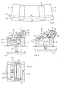
- FIGS. 1 to 3 in various views for the production of can bodies from flat blanks using electrical resistance welding with the aid of welding electrode rolls, which device is also referred to as a resistance roll seam welding machine, points to the machine frame 1 in FIG a magazine 2 on the left-hand side for receiving a stack of flat blanks 3.
- the blanks 3, one of which is shown on a larger scale in FIG. 5, are stacked out of the magazine 2 and arrive at the intermediate table 4 of the deformation station 5 which operates in the manner of a press.
- This is also designed and has the principle of a press 3, a lower press table 7 guided on guide columns 6 and movable up and down. This is opposed by an upper press table 8.
- a blank 3 stacked out of the magazine 2 is first provided in the press or deformation station 5 with the aid of a pressing or embossing tool, not shown, with flat beads 9 shown in FIG. 5 in two areas of the blank, which later have the larger side walls of the rectangular cross section Form can body. These flat beads or indentations 9 serve to stiffen the side walls of the can body. The principle of producing such beads is known and is therefore not shown.
- the flat blank 3 shown on a larger scale in FIG. 5 has at the two opposite ends two edges 10 and 11 which are to be welded together. Furthermore, the blank has a tear strip 13 delimited by pre-scored lines 12, which on one side protrudes beyond the edge 10 Tear tab 14 ends, and which extends over the entire length of the blank.
- FIG. 4 A bending tool 20 used for this is shown in FIG. 4, from which figure the arrangement within the deformation station 5 can be seen.
- the principle of the bending process is shown in Fig. 6 a, b and c.
- the areas of the blank adjoining the two blank edges 10 and 11 to be welded are each bent to the extent of half a side wall of the can body from the flat blank by 90 °.
- the weld seam then comes to lie later in the middle of this side wall of the can body which is rectangular in cross section. 6, these bending processes have already been completed, but they are carried out according to the same principle as shown in FIG. 6.
- a separate bending tool 20 is provided for each bending process and the blank is transported from one bending tool to the next in cycles.
- three bends carried out according to this principle have already been completed, that is to say the cutting regions adjoining the two edges 10 and 11 to be welded are bent up and one of the two wider side surfaces of the can body to be produced is also bent up.
- Each bending tool 20 includes a shaped piece 21 held stationary within the can body to be produced as a counter-tool, which shaped piece has a curved outer surface 22 whose radius of curvature is smaller than the radius of curvature of the rounded corner of the can body to be produced, depending on the elasticity and thickness of the sheet.
- a flat shaped piece section 21a adjoins the curved surface 22.
- the fitting 21 is held stationary above the blank 3.
- the bending tool 20 also includes a pressing tool 23, 24 which is used for pressing from the outside.
- This has a bearing body 23 for a roller 24 mounted in this bearing body, further a guide 25 for the bearing body, on which it is guided in a longitudinally displaceable manner, and a compression spring 26, by means of which the roller 24 is pressed against the blank, if that by one 6a is moved to the parallel axis 27 formed by the curved surface 22 of the curved edge by means of a pivotably mounted lifting rod 28 in FIG. 6a and is moved along the curved surface 22 of the shaped piece 21 in order to bend the blank 3.
- the state then reached is shown in Fig. 6b.
- the bend must be made through an arc of more than 90 ° in order to take into account the material elasticity and the large bending radius, so that a permanent 90 ° bend is subsequently obtained.
- This bend beyond 90 ° can be seen from FIG. 6b, from which figure it can also be seen that the previously bent and opposite wide side surface of the can body, which is still vertically upward at the start of the fourth turning process, which is shown in broken lines in Fig. 6b is shown, this bending process hindered beyond 90 ° and must therefore be temporarily pushed away.
- a two-armed lever 30, which can be pivoted about an axis 31 parallel to the bending edge 22, is additionally present in the bending tool 20 shown in FIG.
- the pivoting plane being located in front of the molding 21 .
- the one lever arm 32 is pivoted upwards by the bearing body 23 for the roller 24 during the upward movement of the bearing body, and as a result the other lever arm 33 of the two-armed lever 30, which is bent towards the inside of the can body to be produced, is also pivoted and thereby presses the side wall of the can body to be produced temporarily to the outside.
- the offset of the two-armed lever 30 can be seen from Fig. 6c. As already mentioned, this two-armed lever 30 is not present in the other bending tools of the same design for the previously produced bends.
- the blank 3 is held on the intermediate table 4 during the production of the bend by a holding device 34 with the cooperation of a spring 35.
- a bar 40 Arranged underneath the intermediate table 4 as a transport device is a bar 40, which is oscillating in the feed direction and has pawls 41 pivotably hinged to it at intervals.
- the principle of jack transport is well known.
- the pawls 41 pivot completely into the bar 40 when the bar retracts below a can body and are moved upwards under the action of a spring 42 in order to engage at the rear edge of a can body formed by a blank 3.
- a part of this transport bar 40 with the pawl 41 and the spring 42 is shown in FIG. 7 and can be seen more clearly here.
- This transport bar 40 shown broken off in FIG.
- the bending tools 20 are arranged one behind the other in the feed direction of this transport bar, the blank 3 is intermittent by means of the feed bar 40 and the pawl 41 moved from one to the next bending station 20 and thereby a bend is made by each of the bending tools 20, at the same time with successive blanks 3, by the lifting rods 28 through the movable table 7 of the press for all bending tools 20 be moved upwards.
- the deformation station 5 is followed by a conveyor line 45 for the can bodies to be welded, formed from the blanks 3, which conveyor line extends to just before the welding station 46 located at the end, in which the two welding electrode rollers 47 extend and 48 for the production of the weld seam.
- a conveyor line 45 for the can bodies to be welded, formed from the blanks 3, which conveyor line extends to just before the welding station 46 located at the end, in which the two welding electrode rollers 47 extend and 48 for the production of the weld seam.
- the oscillatingly moving transport device 40, 41 which has the bar 40 with the pawls 41, which also includes a crank drive 50, which can be seen in FIG. 1, for the oscillating movement of the bar 40.
- the crank 51 moves a carriage 53 connected to it via a connecting piece 52, which is guided on two guide columns 54 arranged next to one another.
- the blank 3 on the edge 10 to be welded has a projecting tear-open tongue 14 at the end of the tear-off strip 13 and the can body 3 tapers towards its one end.
- the can body 3 which is in the last transport position in front of the welding electrode rollers 47 and 48 in the last transport position, is transported further by independently driven further transport means in the form of a pair of pliers 70, 71 consisting of two parallel and simultaneously operated pliers 70 and 71 which detects the can body on both sides of the edges 10 and 11 to be welded at the rear edge at the top and leads further in the feed direction between the welding electrode rollers 47 and 48, as can be seen from FIG. 9, in which the two adjacent pliers 70 and 71 can be seen.
- the two pliers 70 and 71 are operated by compressed air for opening and closing, for which purpose the compressed air is fed through a line 72 into a device 73 for generating the actuating stroke reached.
- the two pliers 70 and 71 are fastened to a plier carriage 74 which is moved forward in the direction of advance by the action of a spring 75 and which is guided accordingly for a to-and-fro movement, which is not shown further.
- the return movement of the tong carriage 74 into the position shown in FIG. 7 is carried out by a separate, further carriage 76 which is connected to a separate drive via a crank mechanism 77.
- the first means of transport consisting of the bar 40 with the pawls 41 and the second means of transport consisting of the double pliers 70, 71 are thus driven independently of one another and are precisely matched to one another in their cyclical operation.
- the Z-shaped guide rail used in known resistance seam welding machines cannot be used if a protruding tear-open tongue 14 protrudes from the one blank edge 10.
- the guide rail 62 used in the present case and shown on a larger scale in FIG. 10 has a groove 64 for receiving the cutting edge 10 only in a short guide rail section 63 at one end of the guide rail, the tear-open tongue 14 protruding from this edge in front of this guide rail section 63 comes to rest.
- a stop body 65 is provided in the area of the other end of the guide rail 62, which is arranged at the end of a pivotably mounted two-armed lever 66. At the other end of this lever 66 there is a roller 67 which acts against the control curve 68 of a bar 69 rests.
- This bar 69 is fastened to the tong carriage 74 and moves with it forward in the feed direction, so that after a certain distance the pivotable lever 66 is pivoted so that the stop body 65 is removed from the cutting edge 10 so that the tear-open tongue 14 takes this place can happen.
- the stop body 65 must also be pivoted away so that the double pliers 70, 71, which hold the can body 3 during this feed movement for inserting the can body between the welding electrode rollers, can move past the stop body 65.
- the guide rail 62 has a continuous groove 62a.
- a calibration device in the form of four rollers 80 to 83 is arranged, which bear against the four rounded corners of the can body 3, which is rectangular in cross section. If, as in the present case, the can body has a cross-section that constantly changes in size over the length of the can, ie tapers towards the one end, the can body with the smaller cross-section is transported lying on the front, which is why the calibration rollers 80-83 must be movably arranged. so that they can move sideways because the cross section of the can body is larger at the rear end.
- the two rollers 80 and 81 are therefore arranged at the end of pivotably mounted levers 84 and 85, which are pivotable in the horizontal plane.
- the two rollers 82 and 83 are each acted upon by a compression spring 86 which acts against the roller and is supported against a holding device 87.
- the rollers 80-83 have a concave outer profile, the radius of curvature of which corresponds to the radius of curvature of the rounded corners of the can body 3.
- can bodies with a rectangular cross section and rounded corners can be produced, in which at the same time the size of the cross section changes continuously over the length of the can body, i.e. there is a taper.
- the pivotable stop 65 on the guide rail 62 can be dispensed with, for example, and another guide rail can be used, which makes it possible to guide and transport the can body in such a way that the tear-open tongue 14 is in the position shown in FIG Feed direction is located in the front area of the can body, so that a sufficiently long groove can be provided for the edge behind this tear-open tongue.
- the longitudinal seam could also be produced by laser welding. Furthermore, the longitudinal seam could also be produced by an adhesive process.
Priority Applications (1)
| Application Number | Priority Date | Filing Date | Title |
|---|---|---|---|
| AT8888117073T ATE104879T1 (de) | 1987-10-22 | 1988-10-14 | Verfahren und einrichtung zur herstellung von einen unrunden querschnitt aufweisenden dosenkoerpern. |
Applications Claiming Priority (2)
| Application Number | Priority Date | Filing Date | Title |
|---|---|---|---|
| CH4138/87A CH673604A5 (fr) | 1987-10-22 | 1987-10-22 | |
| CH4138/87 | 1987-10-22 |
Publications (3)
| Publication Number | Publication Date |
|---|---|
| EP0312918A2 true EP0312918A2 (fr) | 1989-04-26 |
| EP0312918A3 EP0312918A3 (fr) | 1991-01-02 |
| EP0312918B1 EP0312918B1 (fr) | 1994-04-27 |
Family
ID=4270524
Family Applications (1)
| Application Number | Title | Priority Date | Filing Date |
|---|---|---|---|
| EP88117073A Expired - Lifetime EP0312918B1 (fr) | 1987-10-22 | 1988-10-14 | Procédé et appareil de fabrication d'un corps de boîte à section non circulaire |
Country Status (10)
| Country | Link |
|---|---|
| US (1) | US4947014A (fr) |
| EP (1) | EP0312918B1 (fr) |
| JP (1) | JP2558157B2 (fr) |
| CN (1) | CN1028354C (fr) |
| AT (1) | ATE104879T1 (fr) |
| AU (1) | AU599836B2 (fr) |
| BR (1) | BR8805452A (fr) |
| CH (1) | CH673604A5 (fr) |
| DE (1) | DE3889285D1 (fr) |
| ES (1) | ES2052667T3 (fr) |
Cited By (3)
| Publication number | Priority date | Publication date | Assignee | Title |
|---|---|---|---|---|
| EP0340457A2 (fr) * | 1988-04-29 | 1989-11-08 | Fael S.A. | Dispositif de guidage de corps de boîtes de coupe non circulaire |
| EP0426258A1 (fr) * | 1989-11-01 | 1991-05-08 | Thomassen & Drijver-Verblifa N.V. | Procédé et dispositif pour fabriquer des corps de boîte en métal pourvus d'un revêtement intérieur |
| CN101927973A (zh) * | 2010-04-30 | 2010-12-29 | 东莞市铖泰制罐设备有限公司 | 自动封罐机卷封装置 |
Families Citing this family (4)
| Publication number | Priority date | Publication date | Assignee | Title |
|---|---|---|---|---|
| DE19853366B4 (de) * | 1998-11-19 | 2007-07-19 | Schuler Pressen Gmbh & Co. Kg | Vorrichtung und Verfahren zum Umformen |
| EP1050366A3 (fr) * | 1999-05-01 | 2002-01-02 | Meltog Limited | Mécanisme d'entraínement |
| DE202006016009U1 (de) * | 2006-10-19 | 2008-03-06 | Ackermann, Bruno | Stapelbare Dose |
| CN102688917A (zh) * | 2012-06-07 | 2012-09-26 | 安徽肯达机械科技有限公司 | 一种非圆形截面容器外壳的成形设备和方法 |
Citations (21)
| Publication number | Priority date | Publication date | Assignee | Title |
|---|---|---|---|---|
| GB191403270A (en) * | 1914-02-07 | 1915-05-07 | F E Adams Pressure Tool Co Ltd | Improvements in and connected with Machinery for Operating upon Parts of Metal Boxes and other Articles. |
| DE404765C (de) * | 1923-03-30 | 1924-10-23 | Erdmann Kircheis Maschinenfabr | Maschine zum Biegen von Zargen oder Maenteln zu Blechdosen |
| CH161362A (fr) * | 1931-08-19 | 1933-04-30 | M J B Company | Machine à cintrer les ébauches de corps de boîtes en fer-blanc et objets analogues. |
| FR873358A (fr) * | 1940-02-16 | 1942-07-07 | Karges Hammer Maschinenfabrik | Machine à souder les corps des boîtes à conserves par soudure autogène ou par soudure ordinaire |
| US2352095A (en) * | 1939-06-05 | 1944-06-20 | Carl C Grotnes | Metalworking machine |
| DE825388C (de) * | 1949-04-06 | 1951-12-17 | Kabelwerk Wilhelminenhof A G | Vorrichtung zur Herstellung eines Rohres aus einem Band |
| GB681074A (en) * | 1950-11-10 | 1952-10-15 | Rheem Mfg Co | Improved apparatus for handling barrels and like metal containers during fabrication in a conveyor line |
| DE946618C (de) * | 1954-02-25 | 1956-08-02 | Eisen & Stahlind Ag | Vorrichtung zum Herstellen von Buechsenzargen |
| US2926774A (en) * | 1957-09-10 | 1960-03-01 | American Can Co | Mechanism for controlling advancement of bodies in can bodymaker |
| CH367786A (de) * | 1958-01-31 | 1963-03-15 | Wuragrohr Gmbh | Vorrichtung zum kontinuierlichen Herstellen geschweisster profilierter Rohre aus Metallband |
| CH377766A (de) * | 1958-05-14 | 1964-05-31 | Bell Ag Maschf | Einrichtung zum Formen, Schweissen und Glätten von Blech zum Bilden von Zargen |
| GB1037271A (en) * | 1962-05-03 | 1966-07-27 | Thelma Eugenia Laxo | Can body blank registration apparatus |
| US3606671A (en) * | 1968-07-10 | 1971-09-21 | Pacific Press & Shear Corp | Method and apparatus for forming pole-like structures |
| US3713409A (en) * | 1971-09-09 | 1973-01-30 | Gulf & Western Ind Prod Co | Apparatus and method for bonding adhesive seams on can bodies |
| US3745295A (en) * | 1970-02-10 | 1973-07-10 | Opprecht Paul | Method for automatic manufacture of metal container bodies,and welding machine for application thereof |
| FR2222171A1 (fr) * | 1973-03-23 | 1974-10-18 | Schmalbach Lubeca | |
| DE2805654A1 (de) * | 1977-02-11 | 1978-08-17 | Socapi | Verfahren und vorrichtung zum kaltverformen von blechen |
| JPS58205619A (ja) * | 1982-05-26 | 1983-11-30 | Hitachi Zosen Corp | 角形鋼管製造設備における成形ロ−ル機 |
| DE3336833A1 (de) * | 1983-10-10 | 1985-04-25 | Hermann Klann Metall- und Blechwarenfabrik GmbH, 8300 Landshut | Vorrichtung zur herstellung vieleckiger oder runder dosen |
| DE3516388A1 (de) * | 1984-07-12 | 1986-01-23 | Elpatronic Ag, Zug | Aufreissbarer dosenrumpf |
| JPS61195714A (ja) * | 1985-02-27 | 1986-08-30 | Fujitsu Ltd | プレス曲げ加工方法 |
Family Cites Families (4)
| Publication number | Priority date | Publication date | Assignee | Title |
|---|---|---|---|---|
| US828723A (en) * | 1906-08-14 | Martin J O Donnell | Machine for making can-bodies. | |
| US26658A (en) * | 1860-01-03 | Improvement in the manufacture of shirred goods | ||
| GB1248625A (en) * | 1969-04-11 | 1971-10-06 | Wilkie & Paul Ltd | Improvements in or relating to containers and method of making same |
| EP0165631A1 (fr) * | 1984-06-19 | 1985-12-27 | Thomassen & Drijver-Verblifa N.V. | Méthode de fabrication d'un corps pourvu d'une bande d'ouverture, corps fabriqué et plaque de métal à partir de laquelle le corps à été fabriqué |
-
1987
- 1987-10-22 CH CH4138/87A patent/CH673604A5/de not_active IP Right Cessation
-
1988
- 1988-09-28 AU AU22893/88A patent/AU599836B2/en not_active Ceased
- 1988-10-14 AT AT8888117073T patent/ATE104879T1/de not_active IP Right Cessation
- 1988-10-14 ES ES88117073T patent/ES2052667T3/es not_active Expired - Lifetime
- 1988-10-14 DE DE3889285T patent/DE3889285D1/de not_active Expired - Fee Related
- 1988-10-14 EP EP88117073A patent/EP0312918B1/fr not_active Expired - Lifetime
- 1988-10-19 US US07/259,772 patent/US4947014A/en not_active Expired - Lifetime
- 1988-10-20 CN CN88107250A patent/CN1028354C/zh not_active Expired - Fee Related
- 1988-10-20 JP JP63263006A patent/JP2558157B2/ja not_active Expired - Fee Related
- 1988-10-21 BR BR8805452A patent/BR8805452A/pt not_active IP Right Cessation
Patent Citations (21)
| Publication number | Priority date | Publication date | Assignee | Title |
|---|---|---|---|---|
| GB191403270A (en) * | 1914-02-07 | 1915-05-07 | F E Adams Pressure Tool Co Ltd | Improvements in and connected with Machinery for Operating upon Parts of Metal Boxes and other Articles. |
| DE404765C (de) * | 1923-03-30 | 1924-10-23 | Erdmann Kircheis Maschinenfabr | Maschine zum Biegen von Zargen oder Maenteln zu Blechdosen |
| CH161362A (fr) * | 1931-08-19 | 1933-04-30 | M J B Company | Machine à cintrer les ébauches de corps de boîtes en fer-blanc et objets analogues. |
| US2352095A (en) * | 1939-06-05 | 1944-06-20 | Carl C Grotnes | Metalworking machine |
| FR873358A (fr) * | 1940-02-16 | 1942-07-07 | Karges Hammer Maschinenfabrik | Machine à souder les corps des boîtes à conserves par soudure autogène ou par soudure ordinaire |
| DE825388C (de) * | 1949-04-06 | 1951-12-17 | Kabelwerk Wilhelminenhof A G | Vorrichtung zur Herstellung eines Rohres aus einem Band |
| GB681074A (en) * | 1950-11-10 | 1952-10-15 | Rheem Mfg Co | Improved apparatus for handling barrels and like metal containers during fabrication in a conveyor line |
| DE946618C (de) * | 1954-02-25 | 1956-08-02 | Eisen & Stahlind Ag | Vorrichtung zum Herstellen von Buechsenzargen |
| US2926774A (en) * | 1957-09-10 | 1960-03-01 | American Can Co | Mechanism for controlling advancement of bodies in can bodymaker |
| CH367786A (de) * | 1958-01-31 | 1963-03-15 | Wuragrohr Gmbh | Vorrichtung zum kontinuierlichen Herstellen geschweisster profilierter Rohre aus Metallband |
| CH377766A (de) * | 1958-05-14 | 1964-05-31 | Bell Ag Maschf | Einrichtung zum Formen, Schweissen und Glätten von Blech zum Bilden von Zargen |
| GB1037271A (en) * | 1962-05-03 | 1966-07-27 | Thelma Eugenia Laxo | Can body blank registration apparatus |
| US3606671A (en) * | 1968-07-10 | 1971-09-21 | Pacific Press & Shear Corp | Method and apparatus for forming pole-like structures |
| US3745295A (en) * | 1970-02-10 | 1973-07-10 | Opprecht Paul | Method for automatic manufacture of metal container bodies,and welding machine for application thereof |
| US3713409A (en) * | 1971-09-09 | 1973-01-30 | Gulf & Western Ind Prod Co | Apparatus and method for bonding adhesive seams on can bodies |
| FR2222171A1 (fr) * | 1973-03-23 | 1974-10-18 | Schmalbach Lubeca | |
| DE2805654A1 (de) * | 1977-02-11 | 1978-08-17 | Socapi | Verfahren und vorrichtung zum kaltverformen von blechen |
| JPS58205619A (ja) * | 1982-05-26 | 1983-11-30 | Hitachi Zosen Corp | 角形鋼管製造設備における成形ロ−ル機 |
| DE3336833A1 (de) * | 1983-10-10 | 1985-04-25 | Hermann Klann Metall- und Blechwarenfabrik GmbH, 8300 Landshut | Vorrichtung zur herstellung vieleckiger oder runder dosen |
| DE3516388A1 (de) * | 1984-07-12 | 1986-01-23 | Elpatronic Ag, Zug | Aufreissbarer dosenrumpf |
| JPS61195714A (ja) * | 1985-02-27 | 1986-08-30 | Fujitsu Ltd | プレス曲げ加工方法 |
Non-Patent Citations (2)
| Title |
|---|
| PATENT ABSTRACTS OF JAPAN, Band 11, Nr. 21 (M-555)[2468], 21. Januar 1987; & JP-A-61 195 714 (FUJITSU LTD) 30-08-1985 * |
| PATENT ABSTRACTS OF JAPAN, Band 8, Nr. 50 (M-281)[1487], 7. März 1984; & JP-A-58 205 619 (HITACHI ZOSEN K.K.) 30-11-1983 * |
Cited By (5)
| Publication number | Priority date | Publication date | Assignee | Title |
|---|---|---|---|---|
| EP0340457A2 (fr) * | 1988-04-29 | 1989-11-08 | Fael S.A. | Dispositif de guidage de corps de boîtes de coupe non circulaire |
| EP0340457A3 (fr) * | 1988-04-29 | 1991-01-02 | Fael S.A. | Dispositif de guidage de corps de boítes de coupe non circulaire |
| EP0426258A1 (fr) * | 1989-11-01 | 1991-05-08 | Thomassen & Drijver-Verblifa N.V. | Procédé et dispositif pour fabriquer des corps de boîte en métal pourvus d'un revêtement intérieur |
| CN101927973A (zh) * | 2010-04-30 | 2010-12-29 | 东莞市铖泰制罐设备有限公司 | 自动封罐机卷封装置 |
| CN101927973B (zh) * | 2010-04-30 | 2012-10-03 | 东莞市铖泰制罐设备有限公司 | 自动封罐机卷封装置 |
Also Published As
| Publication number | Publication date |
|---|---|
| BR8805452A (pt) | 1989-06-27 |
| EP0312918A3 (fr) | 1991-01-02 |
| EP0312918B1 (fr) | 1994-04-27 |
| AU599836B2 (en) | 1990-07-26 |
| CN1028354C (zh) | 1995-05-10 |
| CN1033586A (zh) | 1989-07-05 |
| US4947014A (en) | 1990-08-07 |
| ES2052667T3 (es) | 1994-07-16 |
| AU2289388A (en) | 1989-04-27 |
| JPH01133613A (ja) | 1989-05-25 |
| JP2558157B2 (ja) | 1996-11-27 |
| DE3889285D1 (de) | 1994-06-01 |
| ATE104879T1 (de) | 1994-05-15 |
| CH673604A5 (fr) | 1990-03-30 |
Similar Documents
| Publication | Publication Date | Title |
|---|---|---|
| EP0086364B1 (fr) | Appareil pour sceller un emballage de fluides | |
| DE2812138A1 (de) | Vorrichtung zum falten und verschliessen des kopfes einer faltschachtel | |
| DE3844117C2 (fr) | ||
| EP0162119B1 (fr) | Dispositif pour la fabrication d'un emballage à partir d'un flan plat | |
| DE2705596C2 (de) | Vorrichtung zur Herstellung einseitig offener, trommelartiger Behälter runder oder eckiger Querschnittsgestalt aus Pappe | |
| DE3424782C2 (fr) | ||
| EP2323935B1 (fr) | Procédé et dispositif de transport de pièces d'usinage plates | |
| DE2235933B2 (de) | Verfahren und vorrichtung zum herstellen von lagerschalen | |
| DE3641886A1 (de) | Verfahren und vorrichtung zum abtrennen aufeinanderfolgender rohrstuecke von einem rohr | |
| CH635236A5 (de) | Verfahren und vorrichtung zum aufbringen eines verstaerkungsbandes auf einen reissverschluss mit einem trennbaren endglied. | |
| DE2339518C2 (de) | Vorrichtung zum Herstellen rohrförmiger Behälter-Grundkörper aus einem Zuschnitt | |
| DE3627179C2 (fr) | ||
| EP0312918B1 (fr) | Procédé et appareil de fabrication d'un corps de boîte à section non circulaire | |
| DE3440809A1 (de) | Verfahren und vorrichtung zum verbinden von aufeinanderliegenden blechen durch stanznocken | |
| DE2515338A1 (de) | Vorrichtung zur befestigung von kunststoffgriffen an einem beutelschlauch | |
| DE19820408C2 (de) | Vorrichtung zum Ausstanzen von Behältern aus einer Folienbahn | |
| DE3403020A1 (de) | Verfahren und vorrichtung zur herstellung einer aufreissbaren flaschenkapsel mit aufreisslasche und fingerring | |
| DE2451469A1 (de) | Verfahren und vorrichtung zum falten von bogen aus papier oder dergleichen | |
| WO2001095413A1 (fr) | Separateur en forme de manche et son dispositif de production | |
| DE1923517A1 (de) | Verfahren zur Herstellung von Beuteln und Vorrichtung zur Durchfuehrung des Verfahrens | |
| DE2243007C3 (de) | Verfahren und Vorrichtung zum Herstellen von Hohlkörpern mit einer durch Verkleben hergestellten Seitennaht | |
| DE2351069C3 (de) | Maschine zum Aufteilen von Folien, Platten, Tabletts oder anderen Gegenständen in Quer- und Längsrichtung | |
| DE2152784A1 (de) | Vorrichtung und Verfahren zum Einsetzen von Einpreßmuttern in ein Werkstück | |
| EP0042450B1 (fr) | Procédé pour la fabrication d'enveloppes de pots d'échappement à joint longitudinal plié et dispositif pour la réalisation de ce procédé | |
| DE2512005C2 (de) | Vorrichtung zur Verpackung von Gegenständen zwischen zwei miteinander verschweißbaren Folien |
Legal Events
| Date | Code | Title | Description |
|---|---|---|---|
| PUAI | Public reference made under article 153(3) epc to a published international application that has entered the european phase |
Free format text: ORIGINAL CODE: 0009012 |
|
| AK | Designated contracting states |
Kind code of ref document: A2 Designated state(s): AT BE DE ES FR GB GR IT NL SE |
|
| PUAL | Search report despatched |
Free format text: ORIGINAL CODE: 0009013 |
|
| AK | Designated contracting states |
Kind code of ref document: A3 Designated state(s): AT BE DE ES FR GB GR IT NL SE |
|
| 17P | Request for examination filed |
Effective date: 19910131 |
|
| 17Q | First examination report despatched |
Effective date: 19921228 |
|
| GRAA | (expected) grant |
Free format text: ORIGINAL CODE: 0009210 |
|
| AK | Designated contracting states |
Kind code of ref document: B1 Designated state(s): AT BE DE ES FR GB GR IT NL SE |
|
| PG25 | Lapsed in a contracting state [announced via postgrant information from national office to epo] |
Ref country code: NL Effective date: 19940427 Ref country code: GR Free format text: LAPSE BECAUSE OF FAILURE TO SUBMIT A TRANSLATION OF THE DESCRIPTION OR TO PAY THE FEE WITHIN THE PRESCRIBED TIME-LIMIT Effective date: 19940427 |
|
| REF | Corresponds to: |
Ref document number: 104879 Country of ref document: AT Date of ref document: 19940515 Kind code of ref document: T |
|
| ITF | It: translation for a ep patent filed |
Owner name: ING. A. GIAMBROCONO & C. S.R.L. |
|
| GBT | Gb: translation of ep patent filed (gb section 77(6)(a)/1977) |
Effective date: 19940504 |
|
| REF | Corresponds to: |
Ref document number: 3889285 Country of ref document: DE Date of ref document: 19940601 |
|
| REG | Reference to a national code |
Ref country code: ES Ref legal event code: FG2A Ref document number: 2052667 Country of ref document: ES Kind code of ref document: T3 |
|
| ET | Fr: translation filed | ||
| NLV1 | Nl: lapsed or annulled due to failure to fulfill the requirements of art. 29p and 29m of the patents act | ||
| EAL | Se: european patent in force in sweden |
Ref document number: 88117073.2 |
|
| PLBE | No opposition filed within time limit |
Free format text: ORIGINAL CODE: 0009261 |
|
| STAA | Information on the status of an ep patent application or granted ep patent |
Free format text: STATUS: NO OPPOSITION FILED WITHIN TIME LIMIT |
|
| 26N | No opposition filed | ||
| REG | Reference to a national code |
Ref country code: GB Ref legal event code: IF02 |
|
| PGFP | Annual fee paid to national office [announced via postgrant information from national office to epo] |
Ref country code: DE Payment date: 20041007 Year of fee payment: 17 |
|
| PGFP | Annual fee paid to national office [announced via postgrant information from national office to epo] |
Ref country code: FR Payment date: 20041008 Year of fee payment: 17 |
|
| PGFP | Annual fee paid to national office [announced via postgrant information from national office to epo] |
Ref country code: GB Payment date: 20041013 Year of fee payment: 17 Ref country code: AT Payment date: 20041013 Year of fee payment: 17 |
|
| PGFP | Annual fee paid to national office [announced via postgrant information from national office to epo] |
Ref country code: SE Payment date: 20041027 Year of fee payment: 17 |
|
| PGFP | Annual fee paid to national office [announced via postgrant information from national office to epo] |
Ref country code: ES Payment date: 20041118 Year of fee payment: 17 |
|
| PGFP | Annual fee paid to national office [announced via postgrant information from national office to epo] |
Ref country code: BE Payment date: 20041215 Year of fee payment: 17 |
|
| PG25 | Lapsed in a contracting state [announced via postgrant information from national office to epo] |
Ref country code: IT Free format text: LAPSE BECAUSE OF NON-PAYMENT OF DUE FEES Effective date: 20051014 Ref country code: AT Free format text: LAPSE BECAUSE OF NON-PAYMENT OF DUE FEES Effective date: 20051014 |
|
| PG25 | Lapsed in a contracting state [announced via postgrant information from national office to epo] |
Ref country code: SE Free format text: LAPSE BECAUSE OF NON-PAYMENT OF DUE FEES Effective date: 20051015 Ref country code: ES Free format text: LAPSE BECAUSE OF NON-PAYMENT OF DUE FEES Effective date: 20051015 |
|
| PG25 | Lapsed in a contracting state [announced via postgrant information from national office to epo] |
Ref country code: BE Free format text: LAPSE BECAUSE OF NON-PAYMENT OF DUE FEES Effective date: 20051031 |
|
| PG25 | Lapsed in a contracting state [announced via postgrant information from national office to epo] |
Ref country code: DE Free format text: LAPSE BECAUSE OF NON-PAYMENT OF DUE FEES Effective date: 20060503 |
|
| EUG | Se: european patent has lapsed | ||
| GBPC | Gb: european patent ceased through non-payment of renewal fee |
Effective date: 20051014 |
|
| PG25 | Lapsed in a contracting state [announced via postgrant information from national office to epo] |
Ref country code: FR Free format text: LAPSE BECAUSE OF NON-PAYMENT OF DUE FEES Effective date: 20060630 |
|
| REG | Reference to a national code |
Ref country code: FR Ref legal event code: ST Effective date: 20060630 |
|
| REG | Reference to a national code |
Ref country code: ES Ref legal event code: FD2A Effective date: 20051015 |
|
| BERE | Be: lapsed |
Owner name: S.A. *FAEL Effective date: 20051031 |