EP0304085B1 - Hydraulische Steuereinrichtung für ein stufenloses Riemenscheibengetriebe für Fahrzeuge - Google Patents
Hydraulische Steuereinrichtung für ein stufenloses Riemenscheibengetriebe für Fahrzeuge Download PDFInfo
- Publication number
- EP0304085B1 EP0304085B1 EP88113523A EP88113523A EP0304085B1 EP 0304085 B1 EP0304085 B1 EP 0304085B1 EP 88113523 A EP88113523 A EP 88113523A EP 88113523 A EP88113523 A EP 88113523A EP 0304085 B1 EP0304085 B1 EP 0304085B1
- Authority
- EP
- European Patent Office
- Prior art keywords
- pressure
- valve
- line
- spool
- control device
- Prior art date
- Legal status (The legal status is an assumption and is not a legal conclusion. Google has not performed a legal analysis and makes no representation as to the accuracy of the status listed.)
- Expired - Lifetime
Links
Images


Classifications
-
- B—PERFORMING OPERATIONS; TRANSPORTING
- B60—VEHICLES IN GENERAL
- B60W—CONJOINT CONTROL OF VEHICLE SUB-UNITS OF DIFFERENT TYPE OR DIFFERENT FUNCTION; CONTROL SYSTEMS SPECIALLY ADAPTED FOR HYBRID VEHICLES; ROAD VEHICLE DRIVE CONTROL SYSTEMS FOR PURPOSES NOT RELATED TO THE CONTROL OF A PARTICULAR SUB-UNIT
- B60W30/00—Purposes of road vehicle drive control systems not related to the control of a particular sub-unit, e.g. of systems using conjoint control of vehicle sub-units
- B60W30/18—Propelling the vehicle
-
- B—PERFORMING OPERATIONS; TRANSPORTING
- B60—VEHICLES IN GENERAL
- B60W—CONJOINT CONTROL OF VEHICLE SUB-UNITS OF DIFFERENT TYPE OR DIFFERENT FUNCTION; CONTROL SYSTEMS SPECIALLY ADAPTED FOR HYBRID VEHICLES; ROAD VEHICLE DRIVE CONTROL SYSTEMS FOR PURPOSES NOT RELATED TO THE CONTROL OF A PARTICULAR SUB-UNIT
- B60W10/00—Conjoint control of vehicle sub-units of different type or different function
- B60W10/04—Conjoint control of vehicle sub-units of different type or different function including control of propulsion units
-
- B—PERFORMING OPERATIONS; TRANSPORTING
- B60—VEHICLES IN GENERAL
- B60W—CONJOINT CONTROL OF VEHICLE SUB-UNITS OF DIFFERENT TYPE OR DIFFERENT FUNCTION; CONTROL SYSTEMS SPECIALLY ADAPTED FOR HYBRID VEHICLES; ROAD VEHICLE DRIVE CONTROL SYSTEMS FOR PURPOSES NOT RELATED TO THE CONTROL OF A PARTICULAR SUB-UNIT
- B60W10/00—Conjoint control of vehicle sub-units of different type or different function
- B60W10/10—Conjoint control of vehicle sub-units of different type or different function including control of change-speed gearings
- B60W10/101—Infinitely variable gearings
-
- B—PERFORMING OPERATIONS; TRANSPORTING
- B60—VEHICLES IN GENERAL
- B60W—CONJOINT CONTROL OF VEHICLE SUB-UNITS OF DIFFERENT TYPE OR DIFFERENT FUNCTION; CONTROL SYSTEMS SPECIALLY ADAPTED FOR HYBRID VEHICLES; ROAD VEHICLE DRIVE CONTROL SYSTEMS FOR PURPOSES NOT RELATED TO THE CONTROL OF A PARTICULAR SUB-UNIT
- B60W30/00—Purposes of road vehicle drive control systems not related to the control of a particular sub-unit, e.g. of systems using conjoint control of vehicle sub-units
- B60W30/18—Propelling the vehicle
- B60W30/1819—Propulsion control with control means using analogue circuits, relays or mechanical links
-
- F—MECHANICAL ENGINEERING; LIGHTING; HEATING; WEAPONS; BLASTING
- F16—ENGINEERING ELEMENTS AND UNITS; GENERAL MEASURES FOR PRODUCING AND MAINTAINING EFFECTIVE FUNCTIONING OF MACHINES OR INSTALLATIONS; THERMAL INSULATION IN GENERAL
- F16H—GEARING
- F16H47/00—Combinations of mechanical gearing with fluid clutches or fluid gearing
- F16H47/06—Combinations of mechanical gearing with fluid clutches or fluid gearing the fluid gearing being of the hydrokinetic type
- F16H47/065—Combinations of mechanical gearing with fluid clutches or fluid gearing the fluid gearing being of the hydrokinetic type the mechanical gearing comprising gearing of the friction or endless flexible member type
-
- F—MECHANICAL ENGINEERING; LIGHTING; HEATING; WEAPONS; BLASTING
- F16—ENGINEERING ELEMENTS AND UNITS; GENERAL MEASURES FOR PRODUCING AND MAINTAINING EFFECTIVE FUNCTIONING OF MACHINES OR INSTALLATIONS; THERMAL INSULATION IN GENERAL
- F16H—GEARING
- F16H61/00—Control functions within control units of change-speed- or reversing-gearings for conveying rotary motion ; Control of exclusively fluid gearing, friction gearing, gearings with endless flexible members or other particular types of gearing
- F16H61/66—Control functions within control units of change-speed- or reversing-gearings for conveying rotary motion ; Control of exclusively fluid gearing, friction gearing, gearings with endless flexible members or other particular types of gearing specially adapted for continuously variable gearings
- F16H61/662—Control functions within control units of change-speed- or reversing-gearings for conveying rotary motion ; Control of exclusively fluid gearing, friction gearing, gearings with endless flexible members or other particular types of gearing specially adapted for continuously variable gearings with endless flexible members
- F16H61/66254—Control functions within control units of change-speed- or reversing-gearings for conveying rotary motion ; Control of exclusively fluid gearing, friction gearing, gearings with endless flexible members or other particular types of gearing specially adapted for continuously variable gearings with endless flexible members controlling of shifting being influenced by a signal derived from the engine and the main coupling
- F16H61/66259—Control functions within control units of change-speed- or reversing-gearings for conveying rotary motion ; Control of exclusively fluid gearing, friction gearing, gearings with endless flexible members or other particular types of gearing specially adapted for continuously variable gearings with endless flexible members controlling of shifting being influenced by a signal derived from the engine and the main coupling using electrical or electronical sensing or control means
-
- F—MECHANICAL ENGINEERING; LIGHTING; HEATING; WEAPONS; BLASTING
- F02—COMBUSTION ENGINES; HOT-GAS OR COMBUSTION-PRODUCT ENGINE PLANTS
- F02B—INTERNAL-COMBUSTION PISTON ENGINES; COMBUSTION ENGINES IN GENERAL
- F02B75/00—Other engines
- F02B75/02—Engines characterised by their cycles, e.g. six-stroke
- F02B2075/022—Engines characterised by their cycles, e.g. six-stroke having less than six strokes per cycle
- F02B2075/025—Engines characterised by their cycles, e.g. six-stroke having less than six strokes per cycle two
Definitions
- the present invention relates to a hydraulic control device for controlling a hydraulically operated continuously variable transmission of a belt-and-pulley type for an automotive vehicle as defined by the features of the first part of claim 1 and known from JP-A-61218862 ( ⁇ US-A 4702 725).
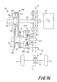
- a power transmitting system wherein power of an engine 10 of a motor vehicle is transmitted to drive wheels 24, via a fluid coupling 12 with a lock-up clutch 36, an auxiliary transmission 14, a belt-and-pulley continuously variable transmission (hereinafter abbreviated as "CVT") 16, an intermediate gear device 18, a differential gear device 20, and drive shafts 22 connected to the drive wheels 24.
- CVT continuously variable transmission
- the fluid coupling 12 has a pump impeller 28 connected to a crankshaft 26 of the engine 10, a turbine 32 fixed to an input shaft 30 of the auxiliary transmission 14 and rotated by rotation of the pump impeller 28 via a fluid in the coupling 12, and the above-indicated lock-up clutch 36 fixed to the input shaft 30 via a damper 34.
- the lock-up clutch 36 is engaged to directly couple the crankshaft 26 to the input shaft 30 when the running speed of the vehicle or the rotating speed of the engine 10 or turbine 32 exceeds a predetermined limit.
- the auxiliary transmission 14 consists of a well known, double-pinion type planetary gear mechanism, which includes: a pair of mutually meshing planetary gears 44, 46 which are rotatably supported by a carrier 42 fixed to an input shaft 38 of the CVT 16 (output shaft of the auxiliary transmission 14); a sun gear 40 which is fixed to the input shaft 30 of the auxiliary transmission 14 (output shaft of the fluid coupling 12) and which meshes with the internal planetary gear 44; a ring gear 48 which meshes with the external planetary gear 46; a REVERSE brake 50 for stopping rotation of the ring gear 48; and a FORWARD clutch 52 for connecting the carrier 42 to the input shaft 30 of the auxiliary transmission 14.
- the REVERSE brake 50 and the FORWARD clutch 52 are hydraulically operated frictional coupling devices. When both of these two devices 50, 52 are placed in their disengaged position, the auxiliary transmission 14 is placed in its neutral position wherein power is not transmitted through the transmission 14.
- the FORWARD clutch 52 When the FORWARD clutch 52 is engaged, the output shaft 30 of the fluid coupling 12 is connected to the input shaft 38 of the CVT 16, whereby power from the engine 10 is transmitted in a forward direction to drive the vehicle frontwards.
- the REVERSE brake 50 is engaged, on the other hand, the direction of rotation of the input shaft 38 of the CVT 16 is reversed with respect to that of the output shaft 30 of the fluid coupling 12, whereby the power from the engine 10 is transmitted in a reverse direction to drive the vehicle rearwards.
- the CVT 16 has a pair of variable-diameter pulleys 56, 58 provided on its input and output shafts 38, 54, respectively, and a transmission belt 60 which connects the input and output pulleys 56, 58.
- the two pulleys 56, 58 have substantially the same nominal diameters.
- Each of the pulleys 56, 58 consists of a fixed rotor 62, 64 fixed to the input or output shaft 38, 54, and a movable rotor 66, 68 which is axially slidable on the shaft 38, 54 and which is rotated with the shaft 38, 54.
- the corresponding input and output hydraulic cylinders 70, 72 have substantially the same pressure-receiving areas.
- a tension of the transmission belt 60 is associated with a force acting thereon, which is produced by the pressure in one of the two cylinders 70, 72 which is provided on the driven pulley 56, 58.
- An oil pump 74 is connected integrally with the pump impeller 28 of the fluid coupling 12 and is consequently driven by the crankshaft 26.
- This pressure source is used as a hydraulic pressure source of a hydraulic control device for controlling the instant power transmitting system.
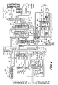
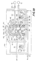
- the hydraulic control device for controlling the power transmitting system generally shown in Fig. 1 is illustrated in Fig. 2.
- the oil pump 74 sucks up a working fluid from a reservoir (not shown) through a strainer 76 and a suction line 78, and delivers the thus pressurized fluid to a first pressure line 80 which has a first line pressure PL1.
- the first line pressure PL1 in the first pressure line 80 is adjusted by a first pressure regulating valve 100 of an overflow or relief type, which is operated to return a portion of the fluid from the pump 74 to the suction line 78 and deliver a portion of the fluid to a LOCK-UP CLUTCH line 92.
- the first line pressure PL1 is reduced into a second line pressure PL2 by a second pressure regulating valve 102 of a pressure reducing type.
- This second pressure regulating valve 102 is provided downstream of the first pressure regulating valve 100, and has a valve spool 110 for selective connection and disconnection of the first and second pressure lines 80 and 82.
- the second pressure regulating valve 102 further has a spring seat 112, a return spring 114 and a plunger 116.
- a chamber 124 Between a first land 118 and a second land 120 of the spool 110, there is formed a chamber 124 to which the second line pressure PL2 is applied as a feedback pressure through a restrictor 122, whereby the spool 110 is biased toward its closed position by the second line pressure PL2.
- the first land 118 is also exposed to a chamber 128 to which a SPEED RATIO pressure Pe (which will be described) is applied through a restrictor 126, whereby the spool 110 is biased toward its closed position by the pressure Pe.
- a SPEED RATIO pressure Pe which will be described
- the spool 110 of the second pressure regulating valve 102 is baised toward its open position, by the return spring 114 via the spring seat 112.
- An outer end face of the plunger 116 is exposed to a chamber 130 to which a THROTTLE pressure Pth (which will be described) is applied, whereby the spool 110 is biased toward its open position by this THROTTLE pressure Pth.
- the first pressure regulating valve 100 includes a valve spool 140, a spring seat 142, a return spring 144 and a plunger 146.
- the spool 140 operates to effect selective connection and disconnection of a port 148a communicating with the first pressure line 80, to and from a drain port 148b or a port 148c.
- An outer end face of a first land 150 of the spool 140 is exposed to a chamber 152 to which the first line pressure PL1 is applied through a restrictor 151, whereby the spool 140 is biased toward its open position by the first line pressure PL1.
- the plunger 146 which is coaxial with the spool 140, is formed with a first land 154 and a second land 156.
- a chamber 158 to which the THROTTLE pressure Pth is applied.
- An outer end face of the first land 154 is exposed to a chamber 160 to which higher one of the second line pressure PL2 and an input cylinder pressure Pin in the input side cylinder 70 is selectively applied, according to an operation of a switch valve 170 which will be described.
- the spool 140 is biased toward its closed position, by a biasing force of the return spring 144 via the spring seat 142.
- the THROTTLE pressure Pth indicated above represents an actual opening angle ⁇ th of a throttle valve of the engine 10, and is produced by a throttle-opening sensing valve 180.
- the SPEED-RATIO pressure Pe represents an actual speed ratio of the CVT 16, and is produced by a speed-ratio sensing valve 182.
- the throttle-opening sensing valve 180 includes: a cam 184 rotated in response to an operation of the throttle valve; a plunger 186 which engages a cam surface of the cam 184 and which is axially moved in relation to an angle of rotation of the cam 184; and a valve spool 190 which is moved to an equilibrium position in which a thrust of the plunger 186 acting on the spool 190 via a spring 188 is balanced with the first line pressure PL1, whereby the first line pressure PL1 is reduced into the THROTTLE pressure Pth which corresponds to the actual opening angle ⁇ th of the throttle valve.
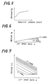
- Fig. 5 shows a relationship between the THROTTLE pressure Pth and the throttle opening angle ⁇ th.
- the THROTTLE pressure Pth is supplied through a fluid line 84 to the first pressure regulating valve 100, the second pressure regulating valve 102, a limit valve 210 and a fourth pressure regulating valve 220.
- the SPEED-RATIO sensing valve 182 includes: a sensing rod 192 which is held in sliding engagement with the movable rotor 66 on the input shaft 38 of the CVT 16, so that the rod 192 is axially moved by an amount equal to an axial displacement of the rotor 66; a spring 194 which produces a biasing force which varies with the position of the sensing rod 192; and a valve spool 198 which receives the biasing force of the spring 194, and which is moved to an equilibrium position in which a thrust based on the biasing force of the spring 194 is balanced with a thrust based on the first line pressure PL1, whereby a rate of flow of the fluid to the drain from the sensing valve 182 is changed.
- the sensing rod 192 is moved into the valve 182. Consequently, the amount of the fluid which is fed into the valve 182 through an orifice 196 and which is discharged to the drain by the spool 198 is reduced, whereby the pressure at a position downstream of the orifice 196 is raised.
- This raised pressure is the SPEED-RATIO pressure Pe, which is increased as the speed ratio "e" of the CVT 16 is increased, as indicated in Fig. 6.
- the thus generated SPEED-RATIO pressure Pe is supplied through a fluid line 86 to the second and fourth pressure regulating valves 102 and 220.
- the limit valve 210 includes a plunger 212, and a valve spool 216 which receives a thrust of a spring 214 and a thrust of the plunger 212, in a direction toward its closed position.
- An outer end face of the plunger 212 is exposed to a chamber 218 to which the THROTTLE pressure Pth is applied.
- the spool 216 which is biased toward its closed position by the thrust of the spring 214 and the thrust of the plunger 212 based on the THROTTLE pressure Pth, is biased in the opposite direction toward its open position, by a thrust based on the SPEED-RATIO pressure Pe.
- the spool 216 When the thrust based on the SPEED-RATIO pressure Pe exceeds a sum of the thrusts of the spring 214 and plunger 212, the spool 216 is placed in the open position in which the fluid line 86 is connected to the drain, to thereby prevent an increase of the SPEED-RATIO pressure Pe beyond an upper limit in relation to the throttle opening angle ⁇ th, as indicated in Fig. 6. Since the SPEED-RATIO pressure Pe is saturated at the upper limit predetermined by the throttle opening angle ⁇ th, the second line pressure PL2 controlled by the second pressure regulating valve 102 according to the equation (1) is prevented from being lowered with a decrease of the throttle opening angle ⁇ th, while the speed ratio "e" of the CVT 16 is relatively high, as indicated in Fig. 7.
- the instant hydraulic control circuit provides the relatively low line pressure (second line pressure PL2) which is varied with the speed ratio "e", for controlling the tension of the transmission belt 60, almost according to an ideal curve as indicated in Fig. 8, without using an electromgnetic pressure regulating servo valve controlled by a microcomputer. Therefore, the hydraulic control device is available at a comparatively reduced cost.
- the fourth pressure regulating valve 220 is adapted to produce a fourth line pressure PL4 for activating the REVERSE brake 50 and the FORWARD clutch 52 of the auxiliary transmission 14.
- the fourth pressure regulating valve 220 includes: a valve spool 222 for selective connection and disconnection of the first pressure line 80 and a fourth pressure line 88; a spring seat 224; a return spring 226; and a plunger 228. Between a first land 230 and a second land 232 of the spool 222, there is formed a chamber 236 to which the fourth line pressure PL4 is applied as a feedback pressure through a restrictor 234. Namely, the spool 222 is biased by the fourth line pressure PL4 in a direction toward its closed position.
- An outer end face of the first land 230 is exposed to a chamber 240 to which the SPEED-RATIO pressure Pe is applied through a restrictor 238, whereby the spool 222 is biased by the SPEED-RATIO pressure Pe toward its closed position.
- the valve spool 222 is biased in a direction toward its open position, by a biasing force of the return spring 226 through a spring seat 224.
- an outer end face of the plunger 228 is exposed to a chamber 242 to which the THROTTLE pressure Pth is applied, whereby the spool 222 is biased toward the open position by the THROTTLE pressure Pth.
- the fourth line pressure PL4 is adjusted to an optimum level, according to an equation similar to the equation (1) given above, based on the SPEED-RATIO pressure Pe and the THROTTLE pressure Pth.
- This optimum level is a minimum level required to permit the auxiliary transmission 14 to transmit a torque without a slip in the REVERSE brake 50 and the FORWARD clutch 52.
- the fourth line pressure PL4 obtained by the fourth pressure regulating valve 220 is supplied to the FORWARD clutch 52 or REVERSE brake 50 through a shift-lever valve 250. That is, the shift-lever valve 250 has a valve spool 254 which is axially moved in relation to an operating position of a shift lever 252 of the vehicle.
- the shift lever 252 When the shift lever 252 is placed in its N (NEUTRAL) position, the fourth line pressure PL4 is not supplied to the auxiliary transmission 14.
- the shift lever 252 is placed in its L (LOW), S (SECOND) or D (DRIVE) position, the fourth line pressure PL4 is supplied primarily to the FORWARD clutch 52 while the fluid is discharged from the REVERSE brake 50.
- the fourth line pressure PL4 is supplied primarily to the REVERSE brake 50 while the fluid is discharged from the FORWARD clutch 52.
- the shift lever 252 placed in its P (PARKING) position, the fluid is discharged from both of the FORWARD clutch 52 and the REVERSE brake 50.
- Accumulators 256 and 258 are connected to the FORWARD clutch 52 and REVERSE brake 50, in order to permit smooth frictional engagements of these members 52, 50.
- the first and second line pressures PL1, PL2 adjusted by the first and second pressure regulating valves 100, 102 are supplied to one and the other of the two hydraulic cylinders 70, 72, through a CVT shift control valve device 260, so that the speed ratio "e" of the CVT 16 is controlled.
- the CVT shift control valve device 260 consists of a shift-direction switching directional control valve 262, and a shift-speed control flow control valve 264. To operate these directional control and flow control valves 262, 264, a pilot pressure Pp produced by a pilot pressure control valve 266 is applied to the valves 262, 264 through a pilot line 90.
- the pilot pressure control valve 266 includes a valve spool 268 for selective connection and disconnection of the first pressure line 80 and the pilot line 90, and a spring 270 for biasing the spool 268 toward its open position.
- the spool 268 is moved to an equilibrium position in which the pilot pressure Pp acting in the direction toward the closed position is balanced with the biasing force of the spring 270.
- the first line pressure PL1 is reduced to the suitable pilot pressure Pp.
- the shift-direction switching directional control valve 262 is a spool valve controlled by a first solenoid valve 272.
- This spool valve 262 has: ports 280a, 280c and 280e which communicate respectively with three connecting passages, i.e., first, second and third connecting passages 274, 276, 278 which connect the instant directional control valve 262 to the shift-speed control flow control valve 264; a drain port 280b which communicates with the drain; a port 280d to which the first line pressure PL1 is applied through a restrictor 282; a port 280f to which the second line pressure PL2 is applied; a valve spool 284 which is slidably movable between a first position (upper stroke end as indicated in Fig.
- the pilot pressure Pp does not act on the lower end of the spool 284. Accordingly, while the first solenoid valve 272 is on, the spool 284 is placed in the second position in which the port 280a and the drain port 280b are disconnected from each other while the ports 280d and 280e are disconnected from each other. At the same time, the ports 280c and 280d communicate with each other, while the ports 280e and 280f communicate with each other. While the solenoid valve 272 is off, the spool 284 is placed in the first position in which the port 280a and the drain port 280b communicate with each other while the ports 280e and 280d communicate with each other.
- the directional control valve 262 is constructed such that the fluid communication between the appropriate two ports 280a-280f occurs while the ports are partially closed by the appropriate lands of the spool 284. This arrangement shortens the operating stroke of the spool 284, thereby improving the operating response of the valve 262.
- the relatively short operating stroke of the spool 284 does not cause a problem in operation, since the cross sectional areas of the ports 280a-280f are determined so as to permit sufficient amounts of flow of the fluid through the partially open ports.
- the shift-speed control flow control valve 264 is a spool valve controlled by a second solenoid valve 290.
- This spool valve 264 includes: ports 292b, 292d and 292f which communicate respectively with the first, second and third connecting passages 274, 276, 278 indicated above; ports 292a and 292c which communicate with the input side hydraulic cylinder 70; a port 292e which communicates with the output side hydraulic cylinder 72; a valve spool 294 which is slidably movable between a first position (upper stroke end as indicated in Fig. 9, by the left half of the spool) and a second position (lower stroke end as indicated in Fig.
- the ports 292c and 292d are disconnected from each other. However, these two ports 292c, 292d only slightly communicate with each other, through a restrictor hole 300 formed through the spool 294. Further, the input side hydraulic cylinder 70 communicates with the ports 292a and 292c, through an input side passage 302 provided with a restrictor 304. The output side hydraulic cylinder 72 communicates with the port 292e through an output side passage 306, and with the second pressure line 82 through a by-pass passage 309 provided with a restrictor 308.
- the flow control valve 264 is constructed such that the fluid communication between the appropriate two ports 292a-292f occurs while the ports are partially closed by the appropriate lands of the spool 294.
- the operating stroke of the spool 294 is made relatively short.
- the fluid in the first pressure line 80 is fed into the input side hydraulic cylinder 70, through the restrictor 282, ports 280d and 280c, second connecting passage 276, ports 292d and 292c, input side passage 302 and restrictor 304, as indicated in solid line in Fig. 9.
- the fluid in the output side hydraulic cylinder 72 is discharged through the output side passage 306, ports 292e and 292f, third connecting passage 278, and ports 280e and 280f, as also indicated in solid line in Fig. 9.
- the first line pressure PL1 in the first pressure line 80 acts on the input side hydraulic cylinder 70
- the second line pressure PL2 in the second pressure line 82 acts on the output side hydraulic cylinder 72.
- the equilibrium between the thrusts of the two cylinders 70, 72 is lost, whereby the CVT 16 is shifted in a direction to increase the speed ratio "e" (in the speed-ratio increasing direction), namely, the speed ratio "e" is increased.
- the fluid in the first pressure line 80 is fed into the output side hydraulic cylinder 72 through the restrictor 282, ports 280d and 280e, third connecting passage 278, ports 292f and 292e and output side passage 306, while the fluid in the input side hydraulic cylinder 70 is discharged through the restrictor 304, input side passage 302, ports 292a and 292b, first connecting passage 274, port 280a and drain port 280b, as indicated in broken line in Fig. 9. Consequently, the first line pressure PL1 in the first pressure line 80 acts on the output side hydraulic cylinder 72, while the considerably low pressure acts on the input side hydraulic cylinder 70.
- the fluid communications between the ports 292a and 292b, between the ports 292c and 292d and between the ports 292e and 292f are permitted or interrupted in response to the on/off operations of the second solenoid valve 290, whereby the flows of the fluid as indicated in solid and broken lines in Fig. 9 are controlled between a non-restricted state and a restricted state. Therefore, the CVT 16 is shifted at a high rate or a low rate, in the speed-ratio decreasing or speed-ratio increasing direction. That is, the speed ratio "e" is rapidly or slowly decreased or increased.
- valve spool 294 is placed in an intermediate position thereof when the second solenoid valve 290 is alternately turned on and off (operated in a duty cycle control mode) .
- the CVT 16 is shift up or down at an intermediate rate.
- a table in Fig. 10 indicates shift-up and shift-down motions of the CVT 16 at the three different rates, in relation to the operating conditions of the first and second solenoid valves 272 and 290.
- the fluid in the first pressure line 80 is supplied to the input side hydraulic cylinder 70 through the restrictor hole 300 in the spool 294, while the fluid in the output side hydraulic cylinder 72 is discharged into the second pressure line 82 through the restrictor 308.
- the fluid in the second pressure line 82 is supplied to the output side hydraulic cylinder 72 through the restrictor 308, while the fluid in the input side hydraulic cylinder 70 is discharged through a small amount of clearance provided between the sliding surfaces of the piston and cylinder block.
- the restrictor 308 is provided to avoid a decrease in the pressure Pout in the output side hydraulic cylinder 72, when the CVT 16 is shifted to decrease the speed ratio "e", with the pressue Pout higher than the pressure Pin in the input side hydraulic cylinder 70.
- the CVT 16 is shifted in the speed-ratio decreasing direction at a relatively low rate when the first and second solenoid valves 272, 290 are both turned off. Therefore, even if the first and second solenoid valves 272, 290 were turned off by an electronic control unit 350 (which will be described) due to short-circuiting of a solenoid of the first or second solenoid valve 272, 290 during running of the vehicle, a rapid change of the speed ratio "e" of the CVT 16 would not occur due to such a short-circuiting trouble. Thus, the above arrangement assures a safe running of the vehicle. Further, since the CVT 16 is shifted down at a low rate in the event of the accidental turning off of the two solenoids, the vehicle can be decelerated and stopped on the roadside, and can be re-started for a repair shop.
- the first line pressue PL1 for the CVT 16 be changed with the speed ratio "e" of the CVT 16, as indicated in Fig. 11 when the vehicle runs in a positive-torque condition (wherein the torque is transmitted from the input shaft 38 to the output shaft 54), or as indicated in Fig. 12 when the vehicle runs in an engine-brake condition (wherein the torque is transmitted from the output shaft 54 to the input shaft 38).
- the curves of the graphs in Figs. 11 and 12 indicate the required pressure levels when the speed ratio "e" of the CVT 16 is changed over its entire range, where the input shaft 38 is rotated with a constant torque.
- the pressure Pin in the input side hydraulic cylinder 70 is larger than the pressure Pout in the output side hydraulic cylinder 72 when the vehicle runs in the positive-torque condition, as indicated in Fig. 11, and the pressure Pout is larger than the pressure Pin when the vehicle runs in the engine-brake condition, as indicated in Fig. 12.
- the pressure in the hydraulic cylinder 70, 72 which is on the driving side is larger than that in the hydraulic cylinder on the driven side.
- the first line pressure PL1 be higher than the pressure Pin by an extra value ⁇ which is a required minimum for giving the thurst to the driving side cylinder to establish a desired speed ratio "e", and for minimizing the power loss.
- ⁇ which is a required minimum for giving the thurst to the driving side cylinder to establish a desired speed ratio "e"
- the present hydraulic control device is provided with the switch valve 170 described above, in order to apply the higher one of the pressures Pin and PL2 to the first pressure regulating valve 100.
- the switch valve 170 has: a common port 312 which communicates with the first pressure regulating valve 100 through a restrictor 310; a first port 314 which communicates with the input side passage 302; a second port 316 which communicates with the second pressure line 82; a valve spool 318 which is movable between a first position for connection of the common port 312 to the first port 314, and a second position for connection of the common port 312 to the second port 316; and a spring 320 for biasing the spool 318 toward the second position.
- the opposite ends of the spool 318 receive the pressure Pin in the input side hydraulic cylinder 70 and the second line pressure PL2, respectively, so that the spool 318 is moved toward one of the first and second positions, so as to apply the higher one of the pressures Pin and PL2 to the chamber 160 of the first pressure regulating valve 100.
- the pressure Pin is applied to the chamber 160 when a thrust based on the pressure Pin exceeds a sum of a thrust based on the second line pressure PL2 and a thrust of the spring 319. It is noted that the thrust (biasing force) of the spring 319 is very small.
- the switch valve 170 is adapted to apply the higher one of the pressures Pin (pressure in the input side hydraulic cylinder 70) and PL2 (second line pressure) to the chamber 160 of the first pressure regulating valve 100 as a feedback pressure.
- This arrangement is advantageous in the following situation. That is, upon stopping of the vehicle with the CVT 16 shifted down to obtain the lowest speed ratio "e", the pressure Pin in the input side hydraulic cylinder 70 is released through the drain port 280b, and the pressures Pin and Pout in the input and output side hydraulic cylinders 70, 72 are lowered to extremely low levels. In this event, the first pressure regulating valve 100 operates to establish the first line pressure PL1 based on the second line pressure PL2, immediately after the engine 10 is re-started.
- the speed ratio "e" of the CVT 16 immediately after the re-start of the engine 10 to re-start the vehicle can be adequately controlled.
- the higher one of the pressures Pin and PL2 is utilized as a feedback pressure applied to the chamber 160 of the first pressure regulating valve 100, the first line pressure PL1 can be adjusted to a level which is higher by a relatively small extra amount ⁇ than the pressure Pin, or than the pressure Pout (almost equal to the second line pressure PL2), as indicated in Fig. 13.
- the first line pressure PL1 is controlled to be a required minimum level, so as to minimize a power loss of the hydraulic system.
- a curve indicated in dashed line in Fig. 13 shows the first line pressure PL1 where the switch valve 170 was not provided. In this case, the first line pressure PL1 is higher by an unnecessarily large extra amount than actually required, while the speed ratio "e" is relatively low.
- the extra amount ⁇ indicated above is determined to a required minimum value that permits the CVT 16 to be shifted to change its speed ratio "e" to a suitable value at a suitable rate, over the entire range of the speed ratio.
- the first line pressure PL1 is controlled to be higher than the pressure Pin or Pout, by a suitable extra amount ⁇ , which is determined based on the THROTTLE pressure Pth. That is, the areas of the pressure receiving surfaces of the first pressure regulating valve 100 and the biasing force of the spring 144 are determined so that the first line pressure PL1 is determined as described above.
- the first line pressure PL1 controlled by the first pressure regulating valve 100 increases with the pressure Pin or Pout and the THROTTLE pressure Pth, and the upper limit of the pressure PL1 varies with the THROTTLE pressure Pth.
- the above arrangement prevents an excessive rise of the first line pressure PL1 even if the pressure Pin in the input side hydraulic cylinder 70 is increased to bring the actual speed ratio "e” to a target speed ratio "e*", under a condition where a further decrease of the width of the V groove of the input pulley 56, i.e., a further movement of the movable rotor 66 is mechanically prevented with the actual speed ratio "e” reaching its maximum value, even though the first line pressure PL1 is higher than the pressure Pin by the extra amount ⁇ . Described more specifically, the level of the first line pressure PL1 at point "A" in Fig.
- the first pressure regulating valve 100 is connected to a third pressure line 92 which is provided downstream of the first pressure line 80. Described more particularly, the fluid which flows from the port 148a (communicating with the first pressure line 80) to the port 148b, and the fluid which is delivered through the restrictor 320, are controlled by a third pressure regulating valve 322 to a third line pressure PL3 in the third pressure line 92.
- the third line pressure PL3 is suitably adjusted to activate the lock-up clutch 36 of the fluid coupling 12.
- the third pressure regulating valve 322 is a relief valve which includes a valve spool 324 and a spring 326.
- the spool 324 receives as a feedback pressure the third line pressure PL3 and is thus biased by this pressure PL3 toward its open position, and the spring 326 biases the spool 324 toward the closed position.
- the spool 324 is moved to an equilibrium position in which a thrust based on the above-indicated feedback pressure is balanced with a thrust of the spring 326.
- the fluid in the third pressure line 92 is partially released from the third pressure regulating valve 322 and is fed through a restrictor 328 to various lubricating points of the power transmitting system for lubrication of the relevant parts.
- the third line pressure PL3 is produced.
- the fluid used for the lubrication is returned to the suction line 78.
- the third line pressure PL3 controlled by the third pressure regulating valve 322 is supplied through a lock-up clutch control valve 330, selectively to a CLUTCH ENGAGE passage 332 and a CLUTCH RELEASE passage 334, so that the lock-up clutch 36 of the fluid coupling 12 is engaged and disengaged as needed.
- the lock-up clutch control valve 330 includes a valve spool 336, and a spring 338 for biasing the spool 336 in a direction to release the clutch 36.
- the spool 336 operates to effect selective connection of the third pressure line 92 with the CLUTCH ENGAGE and CLUTCH DISENGAGE passages 332, 334.
- the spool 336 receives the third line pressure PL3 at its opposite ends.
- the spool 336 is moved in the direction to release the lock-up clutch 36 when a third solenoid valve 340 is off or in its closed position.
- the lock-up clutch control valve 330 as shown in Fig. 2 is placed in this condition.
- the third solenoid valve 340 is turned on and opened, the fluid in the third pressure line 92 is released through the solenoid valve 340, which is disposed downstream of a restrictor 342, whereby the third line pressure PL3 which has been applied to a chamber 344 formed on one end of the spool 336 on the side of the spring 338 is removed, and consequently the spool 336 is moved in a direction that causes the lock-up clutch 36 to be engaged.
- a portion of the fluid supplied to the lock-up clutch control valve 330 is supplied to a cooling unit of the power transmitting system.
- the pressure of this fluid is controlled by a cooler by-pass valve 346.
- Reference numeral 348 in Fig. 2 designates a safety valve for preventing an excessive rise of the first line pressure PL1.
- the electronic control unit 350 shown in Fig. 1 serves as control means for controlling the first, second and third solenoid valves 272, 290 and 340 of the hydraulic control device of Fig. 2, so that the speed ratio "e" of the CVT 16 and the engagement of the lock-up clutch 36 of the fluid coupling 12 are controlled.
- the control unit 350 comprises a so-called microcomputer which includes a central processing unit (CPU), a random-access memory (RAM) and a read-only memory (ROM).
- the control unit 350 receives: a signal indicative of a speed Ne of the engine 10, from an engine speed sensor 352; a signal indicative of a rotating speed Nin of the input shaft 38 of the CVT 16, from an input shaft speed sensor 354; a signal indicative of a rotating speed Nout of the output shaft 54 of the CVT 16, from an output shaft speed sensor 356; a signal indicative of the throttle opening angle ⁇ th, from a throttle opening sensor 358; and a signal indicative of a currently selected operating position Ps of the shift lever 252, from a shift-lever position sensor 360.
- the CPU of the control unit 350 processes the received various signals according to a control program stored in the ROM, while utilizing a temporary data storage function of the RAM, and generates output drive signals for controlling the first, second and third solenoid valves 270, 290 and 340.
- the electronic control unit 350 is adapted to execute a main routine (not shown) which includes an initializing step, and a data reading step for storing in the RAM the input signals received from the various sensors. Based on the input signals stored in the RAM, the CPU calculates various parameters such as the rotating speed Nin of the input shaft 38, the rotating speed Nout of the output shaft 54, the speed ratio "e" of the CVT 16 and a running speed "v" of the vehicle.
- the control unit 350 sequentially or selectively performs various control operations for controlling the lock-up clutch 36, CVT 16, and other members of the power transmitting system.
- step S1 An example of the control operation for the CVT 16 is illustrated in the flow chart of Fig. 15, wherein the CPU first executes step S1 in which the various input signals are stored in the RAM, and the speed Ne of the engine 10, speeds Nin and Nout of the input and output shafts 38, 54, throttle opening angle ⁇ th and other parameters are calculated based on the stored input signals.
- step S1 is followed by step S2 in which the speed ratio "e” of the CVT 16, running speed "v” of the vehicle and other parameters are calculated based on the input signals.
- step S3 the control flow goes to step S3 to determine a target speed ratio "e*" of the CVT 16, based on the calculated throttle opening angle ⁇ th and vehicle running speed "v", according to a predetermined relationship among these three parameters.
- This relationship is determined so as to assure sufficient drivability of the vehicle with a minimum fuel consumption by the engine 10. For instance, the relationship is determined so that a currently required output of the engine 10 represented by the throttle opening angle ⁇ th is obtained on an ideal v-Nin* curve which permits a minimum fuel consumption by the engine 10.
- the target engine speed Nin* (desired speed of the input shaft 38 of the CVT 16) is determined by the vehicle running speed "v” and the throttle opening angle ⁇ th, and according to the predetermined relationship.
- the target speed ratio "e*” to obtain the determined target engine speed Nin* is determined.
- the predetermined relationship is stored in the ROM, in the form of a functional formula or data map. In the present embodiment, a plurality of such relationships are stored in the ROM and are selectively used depending upon the currently selected operating position (D or S) of the shift lever 252.
- step S4 the control flow goes to step S4 to calculate a speed-ratio control error, i.e., a difference ("e*" - “e"), and then to step S5 to determine whether the calculated speed-ratio control error ("e*" - "e") is a positive value or not.
- the control flow then goes to step S5a or S5b depending upon the determination in step S5, in order to change the actual speed ratio "e” of the CVT 16 so as to zero the control error ("e*" - “e”). Described more specifically, if a positive decision (YES) is obtained in step S5, step S5a is executed to turn on the first solenoid valve 272 and thereby shift up the CVT 16 to increase its actual speed ratio "e”. If a negative decision (NO) is obtained in step S5, step S5b is implemented to turn off the first solenoid valve 272 and thereby shift down the CVT 16 to decrease the actual speed ratio "e”.
- step S7 a drive signal represented by the determined flow control value Vo is applied to the second solenoid valve 290.
- this drive signal is an ON/OFF signal for continuously changing the duty cycle of the second solenoid valve 290 at a predetermined frequency.
- control unit 350 is adapted to operate the lock-up clutch 36 to the engaged position when the vehicle running speed "v" reaches a predetermined value, for instance, 30 Km/h.
- the instant hydraulic control device provides the first and second line pressures PL1 and PL2 controlled by the respective first and second pressure regulating valves 100 and 102, so that a fluid pressure corresponding to the first line pressure PL1 is applied to one of the input and output side hydraulic cylinders 70, 72, while the fluid in the other hydraulic cylinder 70, 72 is discharged into the second pressure line 80 or the drain.
- the thrust ratio of the two hydraulic cylinders 70, 72 can be varied over a sufficiently wide range, without having to provide the input side hydraulic cylinder 70 with a comparatively large pressure receiving area. This eliminates deterioration of the drivability of the vehicle which would arise if the pressure receiving surface of the hydraulic cylinder 70 has a comparatively large area.
- the first pressure regulating valve 100 is operated in relation to the currently required output of the engine 10 (i.e., throttle opening angle ⁇ th), so that the first line pressure PL1 is regulated to a required minimum value, so as to provide a sufficiently high rate (de/dt) of change of the speed ratio "e” and to keep the hydraulic power loss to a minimum.
- the second pressure regulating valve 102 is operated in relation to the actual speed ratio "e” and the transmission torque (almost proportional to the throttle opening angle ⁇ th), so that the second line pressure PL2 is controlled to be a minimum level required to give the belt 60 a suitable tension or to prevent a slip of the belt 60.
- the instant hydraulic control device significantly reduces the power loss of the vehicle associated with the operation of the oil pump 74.
- the CVT shift control valve device 260 is less likely to be influenced by iron particles, dirts and other foreign matters contained in the working fluid, than a control valve device employing a linear solenoid, because the valve device 260 consists of the directional control valve 262 which has two stable positions, and the flow control valve 264 which has three stable positions (two stroke end positions, and an intermediate position between the stroke end positions).
- the valve device 260 has improved operating reliability.
- the instant valve device 260 is available at a comparatively low cost, in the absence of a linear solenoid, or otherwise required high machining accuracy for assuring smooth movement of the valve spools.
- first line pressure PL1 is controlled to a required minimum level even during a running of the vehicle with the CVT 16 held in the non-load condition, because the first line pressure PL1 is adjusted based on the throttle opening angle ⁇ th, and on the higher one of the pressure Pin in the input side hydraulic cylinder 70 and the second line pressure PL2, as indicated in Fig. 13.
- the instant embodiment is also advantageous in that the first line pressure PL1 adjusted by the first pressure regulating valve 100 according to the equation (2) above will not exceed an upper limit which is determined in relation to the throttle opening angle ⁇ th and the pressure Pin in the input side hydraulic cylinder 70. Consequently, the first line pressure PL1 will not rise excessively even if a further decrease of the width of the V groove of the input pulley 56 is mechanically inhibited before the speed-ratio control error ("e*" - "e") is zeroed.
- the first pressure regulating valve 100 for controlling the first line pressure PL1 is an overflow type
- the second pressure regulating valve 102 for controlling the second line pressure PL2 is a pressure reducing type adapted to reduce the first line pressure PL1 to the second line pressure PL2.
- the third pressure regulating valve 322 for controlling the third line pressure PL3 is an overflow type adapted to adjust the fluid overflowing from the first pressure regulating valve 100 into the third line pressure PL3.
- the first line pressure PL1 is less likely to be influenced by the second line pressure PL2, than in a hydraulic arrangement wherein first and second pressure regulating valves of a pressure reducing type are connected in series.
- the first and second pressure regulating valves 100, 102 are capable of adjusting the first and second line pressures PL1 and PL2, independently of each other. Therefore, the first line pressure PL1 can be maintained at a required minimum level, whereby the hydraulic power loss is minimized.
- the instant hydraulic control device is advantageous in its operation upon re-starting of the engine 10.
- the switch valve 170 connected to the input side hydraulic cylinder 70 and the second pressure line 82 is adapted to apply to the first pressure regulating valve 100 the higher one of the pressure Pin in the cylinder 70 and the second line pressure PL2.
- the first pressure regulating valve 100 is adapted to adjust the first line pressure PL1 to a level which is higher by a suitable amount than the pressure received from the switch valve 170.
- the instant hydraulic control device permits an adequate operation for controlling the CVT 16 with a sufficiently high response, when the vehicle is started following the re-starting of the engine 10 indicated above.
- the spring 319 provided in the switch valve 170 to bias the spool 318 toward its second position provides an advantage that the second line pressure PL2 can be more quickly applied to the first pressure regulating valve 100 when the engine 10 is re-started while the input side hydraulic cylinder 70 is drained through the drain port 280b.
- the spring 319 may be eliminated.
- the SPEED-RATIO pressure Pe generated by the speed-ratio sensing valve 182 is limited by the limit valve 210 in relation to the THROTTLE pressure Pth, as indicated in Fig. 6. Accordingly, the second line pressure PL2 can be controlled so as to approximate to an ideal curve R shown in Fig. 17, which assures an optimum tension of the transmission belt 60. This arrangement effectively eliminates otherwise possible reduction in the durability of the CVT due to excessive tensioning of the belt 60, or slipping of the belt 60. If a conventional pressure regulating valve having a characteristic of linearly changing the second line pressure PL2 with the CVT speed ratio "e" is used, the second line pressure as indicated at PL2′ in Fig.
- the electronic control unit 350 is adapted such that no drive signals are applied to the solenoids of the first and second solenoid valves 272, 290, upon short-circuiting of these solenoids, and therefore the two solenoid valves 270, 290 are both held off, whereby the CVT 16 is slowly shifted down in such an abnormal condition.
- a rapid change in the speed ratio "e" of the CVT 16 is prevented to assure safe running of the vehicle, upon short-circuiting of the solenoids or other electrical troubles.
- the slow decrease of the speed ratio "e” to the minimum value makes it possible to start the vehicle to bring it to a service shop after the vehicle is once stopped on the roadside.
- the instant hydraulic control device employs the first, second and third connecting passages 274, 276 and 278 which connect the shift-direction switching directional control valve 262 and the shift-speed control flow control valve 264.
- the first connecting passage 274 is used primarily for discharging the fluid from the input side hydraulic cylinder 70 for shifting down the CVT 16
- the second connecting passage 276 is used primarily for feeding the fluid into the same cylinder 70 for shifting up the CVT 16. According to this arrangement, the maximum rates at which the CVT 16 is shifted up and down can be determined independently of each other.
- the fluid can be rapidly discharged from the hydraulic cylinder 70 through the drain port 280b, whereby the speed ratio can be decreased at a high rate upon stopping of the vehicle.
- a desired high rate of increase of the speed ratio "e” can be obtained by adjusting the flow resistance of the second connecting passage 276 (by adjusting the inside diameter and length of the passage 276, or a diameter of a restrictor provided in the passage).
- the second and third pressure lines 82 and 92 are disposed downstream of the first pressure line 80, and in parallel with each other. Accordingly, even if the second line pressure PL2 adjusted by the second pressure regulating valve 102 falls below the third line pressure PL3, the pressure PL2 is not be limited to the third line pressure PL3 but is controlled to an optimum value for maintaining a suitable amount of tension of the belt 60. Hence, it is possible to avoid an excessive rise of the first line pressure PL1 due to an unnecessarily high level of the second line pressure PL2. Thus, the hydraulic power loss can be minimized.
- the instant hydraulic control circuit can be simple in construction in the absence of any circuit components such as a flow divider, because of the types of the first, second and third pressure regulating valves 100, 102 and 322. That is, the first pressure regulating valve is an overflow or pressure relief type which adjusts the first line pressure PL1 by varying an amount of overflow or release of the fluid therefrom, and the second pressure regulating valve 102 is a pressure reducing type which adjusts the second line pressure PL2 by reducing the first line pressure PL1.
- the third pressure regulating valve 322 is a pressure relief type which adjusts the third line pressure PL3 by releasing the fluid therefrom to the drain.
- the second pressure regulating valve 102 is also a pressure relief type, a flow divider is required between the first pressure regulating valve 100 and the second and third pressure regulating valves 102, 322, in order to avoid influences of the second and third line pressures PL2 and PL3 upon each other.
- the area A4 of the surface of the spool 140 which receives the first line pressure PL1 (as a feedback pressure) in the speed-ratio decreasing direction is smaller than the area A6 of the surface of the spool 140 which receives the higher one of the pressure Pin (in the input side hydraulic cylinder 70) and the second line pressure PL2 (almost equal to the pressure Pout) in the speed-ratio increasing direction. Accordingly, an influence of the feedback pressure acting on the surface area A4 upon the first line pressure PL1 to be controlled is greater than that of the pressure acting on the surface area A6.
- the first line pressure PL1 controlled by the first pressure regulating valve 100 will not exceed a predetermined upper limit, even if the pressure acting on the surface area A6 becomes equal to the first line pressure PL1 when the pressure Pin in the input side hydraulic cylinder 70 becomes equal to the first line pressure PL1 while a movement of the movable rotor 66 of the input pulley 56 is mechanically prevented.
- the first line pressure PL1 will not rise beyond the predetermined upper limit, even if the movable rotor 66 of the pulley 56 is prevented from being moved to control the speed ratio of the CVT 16.
- the instant hydraulic circuit arrangement does not require a valve to avoiding an excessive rise of the first line pressure PL1, and can therefore be simple in construction.
- the auxiliary transmission 370 is a double-pinion type planetary gear mechanism which includes: a pair of planetary gears 376, 378 which are rotatably supported by a carrier 374 fixed to an intermediate shaft 372 provided coaxially with the output shaft 54; a sun gear 380 which is fixed to the output shaft 54 of the CVT 16 and which meshes with the internal planetary gear 376; a ring gear 382 which meshes with the external planetary gear 378; a REVERSE brake 384 for stopping rotation of the ring gear 382; and a FORWARD clutch 386 for connecting the carrier 374 and the output shaft 54 of the CVT 16.
- the by-pass passage 309 may incorporate a check valve 388 equipped with a restrictor (restrictor/check valve 388), as illustrated in Fig. 19.
- This modified by-pass passage 309 is closed by the restrictor/check valve 388 when the CVT 16 is shifted up with the fluid flowing from the output side hydraulic cylinder 72. Consequently, the by-pass passage 309 does not function as a by-pass passage.
- the by-pass passage 309 is closed by the restrictor/check valve 388 since the pressure Pout in the output side hydraulic cylinder 72 is higher than the second line pressure PL2.
- the fluid is supplied to the output side hydraulic cylinder 72 through the open by-pass passage 309, while the fluid gradually leaks from the input side hydraulic cylinder 70 through the clearance between the sliding surfaces of the cylinder block and the piston.
- the CVT 16 is slowly shifted down to decrease the speed ratio.
- the by-pass passage 309 functions as a by-pass passage during a slow shift-down operation of the CVT 16. Therefore, no provisions are necessary for restraining a leak flow of the fluid from the output side hydraulic cylinder 72 into the second pressure line 82.
- the restrictor of the restrictor/check valve 388 may have a comparatively large diameter, so that the speed ratio can be decreased at a desired low rate, and so that the output side hydraulic cylinder 72 can be sufficiently supplied with the fluid.
- the by-pass passage 309 of the instant embodiment is opened in most cases when the CVT 16 is shifted down, it is possible to avoid an increase in the hydraulic power loss due to a leak flow of the fluid from the hydraulic cylinder 72 into the second pressure line 82, and to avoid a low rate of change of the speed ratio of the CVT 16 and consequent deterioration of the operating response. Even when the pressure Pout in the output side hydraulic cylinder 72 is lowered, the pressure Pout and the second line pressure PL2 can be almost equalized, by reducing the diameter of the restrictor of the restrictor/check valve 388.
- the restrictor is required to perform two incompatible functions, namely, (1) a function of permitting the fluid to flow therethrough from the second pressure line toward the hydraulic cylinder 72 so as to equalize the pressure Pout in the cylinder 72 to the second line pressure PL2 when the pressure Pout becomes lower than the pressure Pin in the input side hydraulic cylinder 70, on the one hand, and (a) a function of restricting a rate of flow of the fluid therethrough to prevent a power loss of the fluid and improve the shifting response of the CVT 16 when the pressure Pout becomes higher than the pressure Pin, on the other hand.
- the belt 60 will not slip on the pulleys 56, 58 even if the amount of leakage of the fluid from the hydraulic cylinder 72 increases due to deterioration of the sealing member.
- Fig. 20 shows a further modified embodiment of the present invention, in which the spool 294 of the shift-speed control flow control valve 264 is slidably received in a cylindrical bore 393 formed in a valve housing 391.
- the spool 294 is formed with a plurality of lands 395 for opening and closing the ports which communicate with the associated passages.
- Each of the lands 395 has a plurality of V-shaped notches 397 which modifies a relationship between the rate of flow of the fluid through the associated ports, and the distance of movement of the spool 294.
- the v-shaped notches 397 formed in the lands 395 of the spool 294 of the instant modified flow control valve 264 serve to permit a gradual, smooth increase in the rate of flow of the fluid through the associated ports as the spool 294 is axially moved from its fully closed position to its fully open position.
- the notches 397 assure a more proportional increase in the flow rate with the distance of movement of the spool 294, particularly when the amount of opening of the ports is relatively small, i.e., while the distance of movement of the spool 294 from its fully closed position is relatively small.
- the instant modified flow control valve 264 of the CVT shift control valve device 260 does not exhibit a sudden increase of the flow rate which occurs if the notches 397 would not be provided.
- the V-shaped notches 397 provided in each land 395 of the spool 294 may be replaced by a chamferred end portion 390, as illustrated in Fig. 21. Further, the same effect as provided by the notches 397 of Fig. 20 or the chamferred end portion 390 of Fig. 21 may be offered by forming a plurality of V-shaped notches 392, 394 in respective parts of the inner circumferential surface of the cylindrical bore 393 on which the lands 395 slide, as illustrated in Figs. 22 and 23. In these specific examples, four notches 392 (Fig. 21) or 394 (Fig. 22) are formed in the circumferential direction of the bore 393.
- the directional control valve 262 and the flow control valve 264 wherein the opposite ends of the spools 284, 294 are exposed to the pilot pressure Pp may be modified such that the springs 286, 296 are disposed on the upper end of the spools (as seen in Fig. 9) and such that the upper end of each spool 284, 294 is exposed to the atmospheric pressure.
- first and second solenoid valves 272, 290 of the directional and flow control valves 262, 264 may be replaced by solenoids which directly act on the spools 284, 294 to control the axial movements thereof, as in an ordinary solenoid-operated control valve.
- the THROTTLE pressure Pth generated by the throttle-opening sensing valve 180 is used as a parameter representative of the currently required output of the engine 10
- the THROTTLE pressure Pth may be replaced by a hydraulic pressure which represents an operating amount of an accelerator pedal of the vehicle if the vehicle does not have a throttle valve as in a diesel engine vehicle.
- the cam 184 used in the illustrated embodiments is mechanically linked with the accelerator pedal, such that the cam 184 is rotated with an increase in the operating amount of the pedal.
- While the illustrated embodiments are adapted to control the CVT 16 such that the actual speed ratio "e" of the CVT 16 coincides with a determined target or desired speed ratio "e*", it is possible to control the CVT 16 such that the actual speed Nin of the input shaft 38 coincides with a determined target or desired speed Nin*.
- pilot pressure Pp generated by the pilot pressure control valve 266 may be replaced by the third line pressure PL3.
- the valve 266 is eliminated, and the cost of the hydraulic control device is accordingly lowered.
- the switch valve 170 is adapted to apply to the first pressure regulating valve 100 the higher one of the pressure Pin in the input side hydraulic cylinder 70 and the second line pressure PL2.
- the pressure Pout in the output side hydraulic cylinder 72 may be used in place of the second line pressure PL2. In this case, the pressure Pout is applied to the second port 316 of the switch valve 170 through the output side passage 306.
- the auxiliary transmission 14 may be modified to have a plurality of forward drive positions, rather than a single forward drive position provided in the illustrated embodiments.
- the fluid coupling 12 may be replaced by an electromagnetic clutch, wet-type clutch or other types of couplings.
- limit valve 210 is adapted to determine the upper limit of the SPEED-RATIO pressure Pe depending upon the THROTTLE pressure Pth in the illustrated embodiment, the principle of the invention may be practiced even if the upper limit value of the pressure Pe is fixed. In this instance, the THROTTLE pressure Pth need not be applied to the plunger 212.
- Fig. 19 may be modified such that the restrictor/check valve 388 is replaced by a restrictor and a separate check valve which are disposed in series connection with each other.
- the restrictor may be provided by determining the diameter and length of the by-pass passage 309 so that the passage 309 provides a suitable resistance to a flow of the fluid.
- the by-pass passage 309 is provided between the output side hydraulic cylinder 72 and the second pressure line 82, so as to facilitate the adjustment of the tension of the belt 60 when the CVT 16 is slowly shifted down.
- another by-pass passage may be provided between the input side hydraulic cylinder 70 and the second pressure line 82, in addition to or in place of the by-pass passage 309.
- This additional by-pass passage incorporates a check valve which is closed when the pressure Pin in the input side hydraulic cylinder 70 becomes higher than the Pressure Pout in the output side hydraulic cylinder 72.
- Figs. 22 and 23 may be modified such that tapered recesses or cutouts are formed in the inner circumferential surface of the cylindrical bore 393, or such that the lands 395 or the inner surface of the bore 393 are formed with stepped recesses or cutouts. These stepped recesses provide the lands 395 with small-diameter portions, or provide the inner surface of the bore 393 with large-diameter portions.
- the second pressure regulating valve 102 used in the illustrated embodiments is a pressure reducing type, it may be a pressure relief or overflow type.
- the second pressure line 82 is connected to the first pressure regulating valve 100, so as to receive the pressure which is released from the valve 100.
- the fluid in question may be used for one of these two purposes, or for other purposes, for example as a pressure source for the fluid coupling.
- the second pressure regulating valve 102 of the illustrated embodiments is operated by hydraulic pressures, it may be a pressure control servo valve which is controlled by a computer (electronic control unit 350).
- the servo valve is controlled so as to provide the second line pressure according to an ideal curve, based on a signal indicative of the speed ratio "e" of the CVT 16, and a signal indicative of a parameter which represents the currently required output of the engine 10, such as the throttle opening angle, vacuum pressure in the suction pipe of the engine, or operating amount of the accelerator pedal.
- THROTTLE pressure Pth produced by the throttle-opening sensing valve 180 is used as a pressure representative of the currently required output of the engine 10
- this hydraulic signal Pth may be replaced by other hydraulic signals provided that the signals represent or closely relates to the output torque of the engine 10.
- a hydraulic pressure representative of the vacuum or reduced pressure in the suction pipe of the engine as sensed by a suitable sensor may be used, as well as the hydraulic pressure representative of the operating amount of the accelerator pedal as indicated above.
- the first pressure regulating valve 100 has additional pressure receiving area or areas.
Landscapes
- Engineering & Computer Science (AREA)
- Mechanical Engineering (AREA)
- General Engineering & Computer Science (AREA)
- Chemical & Material Sciences (AREA)
- Combustion & Propulsion (AREA)
- Transportation (AREA)
- Automation & Control Theory (AREA)
- Control Of Transmission Device (AREA)
Claims (26)
- Hydraulische Steuereinrichtung zum Steuern eines stufenlosen Getriebes des Riemen- und Riemenscheibentyps für ein Fahrzeug, das eine erste und eine zweite Drehwelle (38, 54), jeweils ein Paar an den ersten und zweiten Wellen vorgesehene durchmesserveränderliche Riemenscheiben (56, 58), einen das Paar der Riemenscheiben verbindenden Transmissionsriemen und ein erstes sowie ein zweites hydraulisches Betätigungsglied (70, 72) zum Verändern von wirksamen Durchmessern der Riemenscheiben aufweist, wobei die hydraulische Steuereinrichtung eine erste und eine zweite Druckleitung (80, 82) mit jeweils einem ersten und einem zweiten Leitungsdruck (PL1, PL2) und eine CVT Schaltsteuerventileinrichtung (260) zum Zuführen eines Arbeitsfluids aus einer Hydraulikkraftquelle (74) zu einem der ersten und zweiten hydraulischen Betätigungsglieder aufweist, während es zuläßt, daß das Fluid aus dem anderen der ersten und zweiten Betätigungsglieder abgelassen ist, zum Steuern eines Übersetzungsverhältnisses des stufenlosen Getriebes,
wobei die hydraulische Steuereinrichtung weiterhin ein erstes und zweites druckregulierendes Ventil (100, 102) zum Einstellen des Druckes des aus der Hydraulikkraftquelle (74) zugeführten Arbeitsfluids jeweils auf die ersten und zweiten Leitungsdrücke (PL1, PL2) aufweist, dadurch gekennzeichnet, daß die ersten und zweiten druckregulierenden Ventile den Druck des Arbeitsfluids einstellen derart, daß die ersten und zweiten Leitungsdrücke veränderlich sind und der zweite Leitungsdruck niedriger ist als der erste Leitungsdruck,
daß die CVT Schaltsteuerventileinrichtung (260) ein schaltrichtungsschaltendes Richtungssteuerventil (262) und ein Schaltgeschwindigkeits-Steuer-Strömungssteuerventil (264) aufweist, wobei das Richtungssteuerventil (262) eine Nach-Oben-Schaltstellung aufweist, in der das erste hydraulische Betätigungsglied (70) mit der ersten Druckleitung (80) in Verbindung steht, während der zweite Hydraulikzylinder (72) mit der zweiten Druckleitung (82) in Verbindung steht, um das Getriebe (16) nach oben zu schalten, und eine Nach-Unten-Schaltstellung, in der das erste hydraulische Betätigungsglied mit einer Atmosphäre in Verbindung steht, während das zweite hydraulische Betätigungsglied (70) mit der ersten Druckleitung in Verbindung steht, um das Getriebe nach unten zu schalten; und
daß das Strömungssteuerventil (264) die Geschwindigkeiten der Zuström- und Abflußströmungen des Fluids in das eine oder das andere der ersten und zweiten hydraulischen Betätigungsglieder (70, 72) steuert, um eine Geschwindigkeit zu steuern, mit der das Übersetzungsverhältnis des Getriebes verändert ist, um das Getriebe nach oben zu schalten oder nach unten zu schalten in Abhängigkeit davon, ob das Richtungssteuerventil (262) in der nach Oben-Schaltstellung oder in der Nach-Unten-Schaltstellung angeordnet ist. - Hydraulische Steuereinrichtung nach Anspruch 1, wobei das Richtungssteuerventil (262) ein Spulenventil mit einer Ventilspule (284) aufweist, die axial zwischen gegenüberliegenden Taktenden davon bewegbar ist, welche den ersten oder Nach-Oben-Schalt- und zweiten oder Nach-Unten-Schaltstellung entsprechen, wobei das Richtungssteuerventil (262) weiterhin ein Magnetventil (272) zum Steuern eines an eines der entgegengesetzten Axialenden der Ventilspule (284) angelegten Vordruckes aufweist und dadurch die Ventilspule (284) bewegt.
- Hydraulische Steuereinrichtung nach Anspruch 1, wobei das Strömungssteuerventil (264) ein Spulenventil mit einer Ventilspule (294) aufweist, die axial zwischen entgegengesetzten Taktenden davon bewegbar ist, um die Geschwindigkeit der Zufuhrströmung des Fluids in das eine oder das andere hydraulische Betätigungsglied oder die Geschwindigkeit der Abflußströmung des Fluids aus dem anderen oder dem einen hydraulischen Betätigungsglied zu steuern, wobei das Strömungssteuerventil (264) weiterhin ein Magnetventil (290) aufweist zum Steuern eines Vordruckes, der an eines der entgegengesetzten Axialenden der Ventilspule (294) angelegt ist und dadurch die Ventilspule bewegt.
- Hydraulische Steuereinrichtung nach Anspruch 1, weiterhin gekennzeichnet durch ein Schaltventil (170), das mit dem ersten hydraulischen Betätigungsglied (70) des Paares der hydraulischen Betätigungsglieder, das an der ersten Drehwelle vorgesehen ist und mit der zweiten Druckleitung verbunden ist, wobei das Schaltventil (170) an das erste druckregulierende Ventil (100) einen der Drücke im ersten hydraulischen Betätigungsglied und dem zweiten Leitungsdruck anlegt, welcher der Drücke höher ist als der andere, und wobei das erste druckregulierende Ventil (100) den ersten Leitungsdruck (PL1) reguliert derart, daß der erste Leitungsdruck (PL1) um einen vorbestimmten Betrag höher ist als der aus dem Schaltventil (170) empfangene Druck.
- Hydraulische Steuereinrichtung nach Anspruch 4, wobei das erste druckregulierende Ventil (100) aufweist:
eine Ventilspule (140) zur Verbindung der ersten Druckleitung (80) selektiv mit einer dritten Druckleitung (92) oder einer Saugleitung, um dadurch das Fluid aus der ersten Druckleitung zu entlassen; und eine Feder (44) zum Vorspannen der Ventilspule (140) zu einer geschlossenen Stellung davon, wobei die Ventilspule (140) eine erste druckaufnehmende Fläche aufweist, die den ersten Leitungsdruck aufnimmt, um die Ventilspule (140) zu einer offenen Stellung davon vorzuspannen, eine zweite druckaufnehmende Fläche, die den aus dem Schaltventil (170) zugeführten Druck aufnimmt, um die Ventilspule (140) zur geschlossenen Stellung vorzuspannen und eine dritte druckaufnehmende Fläche, die einen für einen Öffnungswinkel eines Drosselventils (184) des Fahrzeuges repräsentativen Drosseldruck (Pth) aufnimmt, um die Ventilspule (140) zur geschlossenen Stellung vorzuspannen. - Hydraulische Steuereinrichtung nach Anspruch 4, wobei das Schaltventil (170) eine Ventilspule aufweist, die axial beweglich ist zwischen einer ersten Stellung davon zum Anlegen des Drucks im ersten hydraulischen Betätigungsglied (70) an das erste druckregulierende Ventil (100) und einer zweiten Stellung davon zum Anlegen des zweiten Leitungsdrucks (PL2) an das erste druckregulierende Ventil (100), wobei die Ventilspule eine erste druckaufnehmende Fläche aufweist, die den Druck im ersten hydraulischen Betätigungsglied (70) aufnimmt, um die Ventilspule zur ersten Stellung davon vorzuspannen und eine zweite druckaufnehmende Fläche, die den zweiten Leitungsdruck (PL2) aufnimmt, um die Ventilspule zu ihrer zweiten Stellung vorzuspannen.
- Hydraulische Steuereinrichtung nach Anspruch 6, wobei das Schaltventil (170) weiterhin eine Feder (319) aufweist, um die Ventilspule zu ihrer zweiten Stellung vorzuspannen.
- Hydraulische Steuereinrichtung nach Anspruch 1, weiterhin gekennzeichnet durch ein Übersetzungsverhältnis Erfassungsventil (182) zum Erfassen eines tatsächlichen Übersetzungsverhältnisses des stufenlosen Getriebes und Erzeugen eines Übersetzungsverhältnisdrucks (Pe), der für das tatsächliche Übersetzungsverhältnis repräsentativ ist und ein Grenzventil (210) zum Begrenzen einer Zunahme des Übersetzungsverhältnisdrucks (Pe) und wobei
das zweite druckregulierende Ventil (102) ein hydraulisch betätigtes druckregulierendes Ventil aufweist, das den zweiten Leitungsdruck (PL2) reguliert basierend auf dem Übersetzungsverhältnisdruck (Pe). - Hydraulische Steuereinrichtung nach Anspruch 8, wobei das Grenzventil (210) die Zunahme im Übersetzungsverhältnisdruck (Pe) begrenzt im Verhältnis zur gerade erforderten Leistung eines Motors des Fahrzeuges.
- Hydraulische Steuereinrichtung nach Anspruch 9, wobei das Grenzventil (210) eine obere Grenze des Übersetzungsverhältnisdrucks (Pe) ändert basierend auf einem für einen Öffnungswinkel eines Drosselventil (184) des Motors repräsentativen Drosseldrucks (Pth).
- Hydraulische Steuereinrichtung nach Anspruch 10, wobei das Grenzventil (210) eine Ventilspule aufweist zum wahlweisen Verbinden und Lösen eines mit dem Übersetzungsverhältniserfassungsventil (182) in Verbindung stehenden Fluiddurchlasses mit und von einem Ablauf und weiterhin eine Feder (214) aufweist zum Vorspannen der Ventilspule zu einer geschlossenen Stellung davon, wobei ein auf dem Übersetzungsverhältnisdruck (Pe) basierender Schub auf die Ventilspule in einer Richtung zur offenen Stellung davon wirkt, während ein auf dem Drosseldruck (Pth) basierender Schub auf die Ventilspule in einer Richtung zur geschlossenen Stellung davon wirkt, wobei die Ventilspule zur offenen Stellung bewegt ist, um dadurch die Zunahme im Übersetzungsverhältnisdruck (Pe) zu begrenzen, wenn der auf dem Übersetzungsverhältnisdruck (Pe) basierende Schub eine Summe des Schubes überschreitet, der auf dem Drosseldruck (Pth) und dem Schub der Feder (214) basiert.
- Hydraulische Steuereinrichtung nach Anspruch 1, wobei das Strömungssteuerventil (264) ein zweites Spulenventil aufweist, das eine erste Betätigungsstellung besitzt, in der die Zufuhr- und Abfuhrströmungen des Fluids in die und aus den ersten (70) und zweiten hydraulischen Betätigungsgliedern (72), die vom ersten Spulenventil ausgewählt sind, nicht beschränkt sind, eine zweite Betätigungsstellung, in der die Zufuhr- und Abfuhrströmungen beschränkt sind und eine dritte Stellung zwischen den ersten und zweiten Stellungen zwischenliegend, wobei die Schaltsteuerventileinrichtung weiterhin aufweist:
einen ersten Elektromagneten (272), der eingeschaltet ist, um das erste Spulenventil in der ersten Stellung anzuordnen, um das Übersetzungsverhältnis des stufenlosen Getriebes zu erhöhen und der ausgeschaltet ist, um das erste Spulenventil in der zweiten Stellung anzuordnen, um das Übersetzungsverhältnis zu verringern und
einen zweiten Elektromagneten (290), der eingeschaltet ist, um das zweite Spulenventil in der ersten Stellung anzuordnen, um die Geschwindigkeit der Veränderung des Übersetzungsverhältnisses zu erhöhen und der ausgeschaltet ist, um das zweite Spulenventil in der zweiten Stellung anzuordnen, um die Geschwindigkeit der Veränderung des Übersetzungsverhältnisses zu erniedrigen. - Hydraulische Steuereinrichtung nach Anspruch 12, wobei die CVT Schaltsteuerventileinrichtung (260) weiterhin aufweist:
ein erstes Magnetventil (272), das den ersten Elektromagneten aufweist und das einen Vordruck erzeugt, der an einer Ventilspule des ersten Spulenventils angelegt ist, um das erste Spulenventil in der zweiten Stellung anzuordnen, wenn der erste Elektromagnet eingeschaltet ist; und
ein zweites Magnetventil (290), das den zweiten Elektromagneten aufweist und das einen Vordruck erzeugt, der an der Ventilspule des zweiten Spulenventils angelegt ist, um das zweite Spulenventil in der zweiten Stellung anzuordnen, wenn der zweite Elektromagnet ausgeschaltet ist. - Hydraulische Steuereinrichtung nach Anspruch 1, gekennzeichnet durch weiterhin
einen Bypassdurchlaß (309), der einen (72) des Paares hydraulischer Betätigungsglieder und die zweite Druckleitung (82) verbindet und der einen Begrenzer (308) aufweist; und
ein in dem Bypassdurchlaß (309) vorgesehenes Absperrventil (388), wobei das Absperrventil (388) eine Strömung des Fluids durch den Bypassdurchlaß (309) in einer Richtung zum hydraulischen Betätigungsglied (72) hin zuläßt, während es eine Strömung des Fluids durch den Bypassdurchlaß (309) in einer Richtung zur zweiten Druckleitung (82) hin verhindert. - Hydraulische Steuereinrichtung nach Anspruch 1, wobei das Strömungssteuerventil (264) ein Ventilgehäuse (391) mit einer zylindrischen Bohrung (393) und einer Vielzahl von darin gebildeter Öffnungen (292a, 292b, 292d, 292f, 292c, 292e) und eine in der zylindrischen Bohrung (393) verschiebbar aufgenommene Ventilspule (294) aufweist zum Steuern der Geschwindigkeiten der Zufuhr- und Abfuhrströmungen des Fluids, wobei die Ventilspule (294) eine Vielzahl von Stegen (395) zum Öffnen und Schließen der Öffnungen (292a - f) aufweist, eines des Ventilgehäuses (391) und jeder der Stege (395) wenigstens einen Ausschnitt aufweist zum Zulassen einer allmählichen Änderung der Geschwindigkeiten der Zufuhr- und Abfuhrströmungen des Fluids durch die Öffnungen (292a - f), wenn die Ventilspule axial bewegt ist.
- Hydraulische Steuereinrichtung nach Anspruch 15, wobei wenigstens der eine Ausschnitt ausgewählt ist aus der Gruppe bestehend aus einem verjüngten Endabschnitt jedes Stegs (395), wenigstens einer in jedem Steg (395) ausgebildeten V-förmige Kerbe (397) und einem in jedem Steg ausgebildetem gestuften Ausschnitt.
- Hydraulische Steuereinrichtung nach Anspruch 15, wobei der wenigstens eine Ausschnitt ausgewählt ist aus der Gruppe bestehend aus wenigstens einer verjüngten Kerbe, wenigstens einer V-förmigen Kerbe und einem gestuften Ausschnitt, die in einem Abschnitt einer Innenumfangsfläche der zylindrischen Bohrung ausgebildet sind, die verschiebbar mit jedem Steg in Eingriff ist.
- Hydraulische Steuereinrichtung nach Anspruch 1, wobei das Fluid in der ersten Druckleitung (80) in den einen hydraulischen Zylinder eingespeist ist und das Fluid in dem anderen hydraulischen Zylinder in die zweite Druckleitung (82) oder die Atmosphäre ausgebracht ist, während eine dritte Druckleitung (92) vorgesehen ist zur Schmierung eines Kraftübertragungssystems, welches das stufenlose Getriebe aufweist oder für andere Zwecke, wobei die zweite Druckleitung (82) stromabwärts der ersten Druckleitung (80) vorgesehen ist, wobei die hydraulische Steuereinrichtung weiterhin aufweist:
die dritte Druckleitung (92) stromabwärts der ersten Druckleitung (80) und parallel zur zweiten Druckleitung (82) vorgesehen, wobei die dritte Druckleitung (92) den dritten Leitungsdruck (PL3) aufweist; und
ein drittes druckregulierendes Ventil (322) zum Einstellen des dritten Leitungsdruckes (PL3) derart, daß der dritte Leitungsdruck (PL3) niedriger ist als der erste Leitungsdruck (PL1). - Hydraulische Steuereinrichtung nach Anspruch 18, wobei das erste druckregulierende Ventil (100) aus einem druckregulierenden Ventil des Druckentlastungstyps besteht, welches das Fluid aus der ersten Druckleitung (80) in die dritte Druckleitung (92) entläßt, und das zweite druckregulierende Ventil (102) aus einem druckregulierenden Ventil des Druckreduziertyps besteht, das den ersten Leitungsdruck (PL1) auf den zweiten Leitungsdruck (PL2) verringert, wobei das dritte druckregulierende (322) aus einem druckregulierenden Ventil des Druckentlastungstyps besteht, welches das Fluid aus der dritten Druckleitung (92) in einen Ablauf entläßt.
- Hydraulische Steuereinrichtung nach Anspruch 18, wobei das erste druckregulierende Ventil (100) den ersten Leitungsdruck (PL1) einstellt, basierend auf einem Druck, der die gerade erforderte Leistung des Fahrzeuges repräsentiert und einem höheren des zweiten Leitungsdruckes (PL2) und einem Druck in dem ersten hydraulischen Betätigungsglied (70) des Paares der hydraulischen Betätigungsglieder (70, 72), das an der ersten Drehwelle vorgesehen ist derart, daß das Paar der hydraulischen Betätigungsglieder (70, 72) ein Schubverhältnis aufweisen, das zuläßt, daß ein tatsächliches Übersetzungsverhältnis des stufenlosen Getriebes mit einem vorbestimmten Zielübersetzungsverhältnis übereinstimmt.
- Hydraulische Steuereinrichtung nach Anspruch 18, wobei das zweite druckregulierende Ventil (102) den zweiten Leitungsdruck (PL2) einstellt, basierend auf einer gerade erforderten Leistung des Fahrzeuges und eines Übersetzungsverhältnisses des stufenlosen Getriebes derart, daß der Transmissionsriemen eine zum Übertragen eines Drehmoments, das zum Schaffen der gerade erforderten Leistung erforderlich ist, erforderliche minimale Spannung aufweist.
- Hydraulische Steuereinrichtung nach Anspruch 21, wobei das zweite druckregulierende Ventil (102) aus einem hydraulisch betätigten druckregulierenden Ventil besteht, das den zweiten Leitungsdruck (PL2) einstellt, basierend auf einem Druck, repräsentativ für die gerade erforderte Leistung des Fahrzeuges und einem Druck, repräsentativ für das Übersetzungsverhältnis des stufenlosen Getriebes.
- Hydraulische Steuereinrichtung nach Anspruch 21, wobei das zweite druckregulierende Ventil (102) aus einem druckregulierenden Servoventil besteht, das elektrisch gesteuert ist, basierend auf einem Signal repräsentativ für die gerade erforderte Leistung des Fahrzeuges und einem Signal repräsentativ für das Übersetzungsverhältnis des stufenlosen Getriebes.
- Hydraulische Steuereinrichtung nach Anspruch 18, wobei das dritte druckregulierende Ventil (322) zum Aufrechterhalten des dritten Leitungsdrucks (PL3) in einer vorbestimmten konstanten Höhe arbeitet.
- Hydraulische Steuereinrichtung nach Anspruch 1, wobei das erste druckregulierende Ventil (100) eine Ventilspule (140) aufweist, die in einer druckerhöhenden Richtung zum Erhöhen des ersten Leitungsdrucks (PL1) und in einer druckverringernden Richtung zum Verringern des ersten Leitungsdrucks (PL1) bewegbar ist, wobei die Ventilspule (140) eine erste druckaufnehmende Fläche (150) aufweist, die den ersten Leitungsdruck (PL1) aufnimmt, um einen ersten Schub zum Vorspannen der Ventilspule (140) in der ersten druckverringernden Richtung erzeugt und eine zweite druckaufnehmende Fläche (156), die einen höchsten der Drücke in dem Paar der hydraulischen Betätigungsglieder (70, 72) und des zweiten Leitungsdrucks (PL2) aufnimmt, um einen zweiten Schub zum Vorspannen der Ventilspule (140) in der druckerhöhenden Richtung zu erzeugen.
- Hydraulische Steuereinrichtung nach Anspruch 25, wobei das erste druckregulierende Ventil (100) weiterhin eine dritte druckaufnehmende Fläche (154) aufweist, die einen für die gerade erforderte Leistung eines Motors des Fahrzeuges repräsentativen Druck aufnimmt, um einen dritten Schub zum Vorspannen der Ventilspule (140) in der druckerhöhenden Richtung zu erzeugen, wobei das erste druckregulierende Ventil (100) weiterhin eine Rückholfeder (144) aufweist zum Erzeugen eines vierten Schubs zum Vorspannen der Ventilspule (140) in der druckerhöhenden Richtung, wobei der erste Leitungsdruck (PL1) bestimmt ist durch eine Gleichgewichtsstellung der ersten Ventilspule (140), in welcher der erste Schub im Gleichgewicht ist mit einer Summe der zweiten, dritten und vierten Schübe.
Applications Claiming Priority (16)
| Application Number | Priority Date | Filing Date | Title |
|---|---|---|---|
| JP20879487A JP2840719B2 (ja) | 1987-08-21 | 1987-08-21 | 車両用ベルト式無段変速機の油圧制御装置 |
| JP208788/87 | 1987-08-21 | ||
| JP20878887A JP2625748B2 (ja) | 1987-08-21 | 1987-08-21 | 車両用ベルト式無段変速機の油圧制御装置 |
| JP12775987U JPS6432958U (de) | 1987-08-21 | 1987-08-21 | |
| JP208781/87 | 1987-08-21 | ||
| JP208789/87 | 1987-08-21 | ||
| JP208793/87 | 1987-08-21 | ||
| JP62208789A JP2748369B2 (ja) | 1987-08-21 | 1987-08-21 | 車両用ベルト式無段変速機の油圧制御装置 |
| JP20878687A JP2840718B2 (ja) | 1987-08-21 | 1987-08-21 | 車両用ベルト式無段変速機の油圧制御装置 |
| JP20878187A JP2625745B2 (ja) | 1987-08-21 | 1987-08-21 | 車両用ベルト式無段変速機の油圧制御装置 |
| JP62208787A JP2687364B2 (ja) | 1987-08-21 | 1987-08-21 | 車両用ベルト式無段変速機の油圧制御装置 |
| JP127759/87U | 1987-08-21 | ||
| JP208786/87 | 1987-08-21 | ||
| JP208794/87 | 1987-08-21 | ||
| JP208787/87 | 1987-08-21 | ||
| JP20879387A JPS6449761A (en) | 1987-08-21 | 1987-08-21 | Control device for oil pressure of belt type continuously variable transmission of vehicle |
Publications (3)
| Publication Number | Publication Date |
|---|---|
| EP0304085A2 EP0304085A2 (de) | 1989-02-22 |
| EP0304085A3 EP0304085A3 (en) | 1990-10-24 |
| EP0304085B1 true EP0304085B1 (de) | 1993-11-10 |
Family
ID=27573121
Family Applications (1)
| Application Number | Title | Priority Date | Filing Date |
|---|---|---|---|
| EP88113523A Expired - Lifetime EP0304085B1 (de) | 1987-08-21 | 1988-08-19 | Hydraulische Steuereinrichtung für ein stufenloses Riemenscheibengetriebe für Fahrzeuge |
Country Status (3)
| Country | Link |
|---|---|
| US (1) | US4967621A (de) |
| EP (1) | EP0304085B1 (de) |
| DE (1) | DE3885540T2 (de) |
Families Citing this family (40)
| Publication number | Priority date | Publication date | Assignee | Title |
|---|---|---|---|---|
| JP2847781B2 (ja) * | 1989-07-28 | 1999-01-20 | 日産自動車株式会社 | 変速機の制御装置 |
| DE69028961T2 (de) * | 1989-08-09 | 1997-05-22 | Toyota Motor Co Ltd | Hydraulische Steuerung für ein Fahrzeuggetriebesystem, welches Ventile enthält, die die Einschaltung des Rückwärtsganges verhindern |
| EP0412758B1 (de) * | 1989-08-09 | 1994-11-02 | Toyota Jidosha Kabushiki Kaisha | Hydraulisches Steuerungssystem eines stufenlosen Keilriemengetriebes mit einer ausfallsicheren Schutzanordnung |
| JP2629389B2 (ja) * | 1989-12-25 | 1997-07-09 | トヨタ自動車株式会社 | 車両用無段変速機の油圧制御装置 |
| JP2527056B2 (ja) * | 1989-12-25 | 1996-08-21 | トヨタ自動車株式会社 | 車両用無段変速機の油圧制御装置 |
| DE69108754T2 (de) * | 1990-02-01 | 1995-08-17 | Toyota Motor Co Ltd | Hydraulisches Steuerungssystem eines stufenlosen Riemengetriebes mit Riemendruckoptimierung. |
| JP2626257B2 (ja) * | 1990-12-28 | 1997-07-02 | トヨタ自動車株式会社 | 車両用ベルト式無段変速機の油圧制御装置 |
| JP3095258B2 (ja) * | 1991-05-31 | 2000-10-03 | 富士重工業株式会社 | ロックアップトルコン付無段変速機の油圧制御装置 |
| DE4312718A1 (de) * | 1993-04-20 | 1994-11-10 | Zahnradfabrik Friedrichshafen | Schaltvorrichtung für ein stufenloses Getriebe eines Kraftfahrzeuges |
| JP3468439B2 (ja) * | 1995-01-26 | 2003-11-17 | 本田技研工業株式会社 | ベルト式無段変速機のプーリ側圧制御装置 |
| JP3411707B2 (ja) * | 1995-03-02 | 2003-06-03 | 本田技研工業株式会社 | ベルト式無段変速機の制御装置 |
| JP3517299B2 (ja) * | 1995-03-14 | 2004-04-12 | 富士重工業株式会社 | 無段変速機の制御装置 |
| JP3612773B2 (ja) * | 1995-03-24 | 2005-01-19 | アイシン・エィ・ダブリュ株式会社 | 無段変速機 |
| DE69618367T2 (de) * | 1995-03-24 | 2002-11-14 | Aisin Aw Co., Ltd. | Stufenloses Getriebe |
| JP2825198B2 (ja) * | 1995-09-01 | 1998-11-18 | 本田技研工業株式会社 | 車両用無段変速機構の油圧制御装置 |
| DE19604948A1 (de) * | 1996-02-10 | 1997-08-14 | Telefunken Microelectron | Steuerungsanordnung für ein automatisches elektrohydraulisch gesteuertes Getriebe |
| DE19604957A1 (de) * | 1996-02-10 | 1997-08-14 | Audi Ag | Automatisches elektrohydraulisch gesteuertes Getriebe |
| US6398679B1 (en) | 1998-09-14 | 2002-06-04 | Albert W. Brown | Dual Drive continuously variable transmission |
| US6926632B2 (en) * | 1998-09-14 | 2005-08-09 | Albert W. Brown | Dual drive continuously variable transmission |
| DE19912999B4 (de) * | 1999-03-23 | 2006-08-10 | Zf Friedrichshafen Aktiengesellschaft | Verfahren zum Schutz eines Variators bei einem stufenlosen Umschlingungsgetriebe |
| JP4565701B2 (ja) * | 2000-05-12 | 2010-10-20 | 富士重工業株式会社 | 無段変速機の変速制御装置 |
| US6669598B2 (en) * | 2002-02-19 | 2003-12-30 | General Motors Corporation | Line pressure control for a continuously variable transmission |
| EP2381121B1 (de) * | 2003-01-29 | 2012-09-19 | Honda Motor Co., Ltd. | Fehlerbestimmungsvorrichtung für Anfahrkupplung |
| US7540815B2 (en) * | 2005-01-11 | 2009-06-02 | Brown Albert W | In-series two chain continuously variable transmission |
| US20060154761A1 (en) * | 2005-01-11 | 2006-07-13 | Brown Albert W | Single chain continuously variable transmission |
| US7832297B2 (en) | 2005-04-19 | 2010-11-16 | Hewatt Chris B | Method and apparatus for gyroscopic propulsion |
| JP2009191925A (ja) * | 2008-02-13 | 2009-08-27 | Toyota Motor Corp | ベルト挟圧力調節機構診断装置 |
| JP5398317B2 (ja) * | 2009-03-18 | 2014-01-29 | 株式会社エフ・シー・シー | 動力伝達装置 |
| JP5527873B2 (ja) | 2009-03-18 | 2014-06-25 | 株式会社エフ・シー・シー | 動力伝達装置 |
| TWI444550B (zh) * | 2010-06-08 | 2014-07-11 | Ind Tech Res Inst | 複合動力系統無段變速器之液壓控制裝置之控制方法與系統 |
| JP5612624B2 (ja) * | 2012-03-08 | 2014-10-22 | 富士重工業株式会社 | レンジ切替装置 |
| US10941856B2 (en) * | 2014-06-10 | 2021-03-09 | Ford Global Technologies, Llc | Dual sump transmission hydraulic control system |
| JP6621621B2 (ja) * | 2015-09-04 | 2019-12-18 | アイシン・エィ・ダブリュ株式会社 | 自動変速機の油圧制御装置 |
| JP6300777B2 (ja) | 2015-12-10 | 2018-03-28 | 株式会社Subaru | 油圧回路の異常検知装置及び油圧回路の異常検知方法 |
| CN105605215B (zh) * | 2016-01-22 | 2017-09-19 | 奇瑞控股有限公司 | 液压控制方法和系统 |
| JP6267250B2 (ja) * | 2016-02-25 | 2018-01-24 | 株式会社Subaru | 油圧回路の異常検知装置、及び、油圧回路の異常検知方法 |
| CN112623643B (zh) * | 2021-01-26 | 2021-08-24 | 中国矿业大学 | 一种带式输送机张紧系统 |
| CN113126484B (zh) * | 2021-04-18 | 2022-06-28 | 桂林电子科技大学 | 液压系统改进的无模型滑模控制系统和方法 |
| CN114046318B (zh) * | 2021-11-25 | 2024-05-17 | 潍柴动力股份有限公司 | 基于气缸压力的离合器控制方法、装置和设备 |
| CN114857183B (zh) * | 2022-05-20 | 2024-05-17 | 潍柴动力股份有限公司 | 一种气动离合器控制方法和装置 |
Citations (1)
| Publication number | Priority date | Publication date | Assignee | Title |
|---|---|---|---|---|
| JPS61218862A (ja) * | 1985-03-26 | 1986-09-29 | Toyota Motor Corp | ベルト式無段変速機の油圧制御装置 |
Family Cites Families (17)
| Publication number | Priority date | Publication date | Assignee | Title |
|---|---|---|---|---|
| NL165821C (nl) * | 1976-02-09 | 1981-05-15 | Doornes Transmissie Bv | Traploos variabele overbrenging. |
| JPS5829424A (ja) * | 1981-08-18 | 1983-02-21 | 松下電器産業株式会社 | 抽出装置 |
| US4559850A (en) * | 1982-11-30 | 1985-12-24 | Aisin-Warner, Ltd. | Stepless automatic transmission for motor vehicles |
| US4699604A (en) * | 1982-12-27 | 1987-10-13 | Aisin-Warner K.K. | Reduction ratio controlling mechanism for a continuously variable automatic transmission of a vehicle |
| EP0117264B1 (de) * | 1983-02-25 | 1987-06-03 | Nissan Motor Co., Ltd. | Steuerung für stufenlos verstellbare Keilriemengetriebe |
| JPS59159456A (ja) * | 1983-02-26 | 1984-09-10 | Toyota Motor Corp | ベルト式無段変速機の油圧装置 |
| DE3315537C2 (de) * | 1983-04-29 | 1993-12-09 | Aisin Warner | Druckregelsystem für ein automatisches Getriebe, insbesondere für Kraftfahrzeuge |
| JPS6095262A (ja) * | 1983-10-28 | 1985-05-28 | Toyota Motor Corp | ベルト式無段変速機の油圧制御装置 |
| JPS60104847A (ja) * | 1983-11-11 | 1985-06-10 | Toyota Motor Corp | 自動車用無段変速機のライン圧制御装置 |
| US4547178A (en) * | 1983-12-01 | 1985-10-15 | Fuji Medical Instruments Mfg. Co., Ltd. | Control system for an automatic transmission for a vehicle |
| US4653353A (en) * | 1983-12-24 | 1987-03-31 | Toyota Jidosha Kabushiki Kaisha | Spool-type control valve assembly with reduced spool stroke for hydraulic belt-and-pulley type continuously variable transmission |
| JPS612957A (ja) * | 1984-06-18 | 1986-01-08 | Toyota Motor Corp | 無段変速機付き動力伝達装置の油圧制御装置 |
| DE3664195D1 (en) * | 1985-03-12 | 1989-08-10 | Honda Motor Co Ltd | Infinitely variable transmission |
| US4857034A (en) * | 1986-02-22 | 1989-08-15 | Toyota Jidosha Kabushiki Kaisha | Hydraulic control system for continuously variable transmission for automotive vehicle |
| JPS62196446A (ja) * | 1986-02-22 | 1987-08-29 | Toyota Motor Corp | 車両用ベルト式無段変速機の油圧制御装置 |
| US4772249A (en) * | 1986-02-22 | 1988-09-20 | Toyota Jidosha Kabushiki Kaisha | Hydraulic control system for continuously variable transmission for automotive vehicle |
| EP0243539A1 (de) * | 1986-04-29 | 1987-11-04 | Koninklijke Philips Electronics N.V. | Kaffeemaschine |
-
1988
- 1988-08-19 EP EP88113523A patent/EP0304085B1/de not_active Expired - Lifetime
- 1988-08-19 DE DE88113523T patent/DE3885540T2/de not_active Expired - Fee Related
-
1989
- 1989-12-04 US US07/443,845 patent/US4967621A/en not_active Expired - Lifetime
Patent Citations (1)
| Publication number | Priority date | Publication date | Assignee | Title |
|---|---|---|---|---|
| JPS61218862A (ja) * | 1985-03-26 | 1986-09-29 | Toyota Motor Corp | ベルト式無段変速機の油圧制御装置 |
Also Published As
| Publication number | Publication date |
|---|---|
| DE3885540D1 (de) | 1993-12-16 |
| EP0304085A3 (en) | 1990-10-24 |
| DE3885540T2 (de) | 1994-03-17 |
| EP0304085A2 (de) | 1989-02-22 |
| US4967621A (en) | 1990-11-06 |
Similar Documents
| Publication | Publication Date | Title |
|---|---|---|
| EP0304085B1 (de) | Hydraulische Steuereinrichtung für ein stufenloses Riemenscheibengetriebe für Fahrzeuge | |
| US4867732A (en) | Control device for belt-and-pulley type continuously variable transmission for a vehicle | |
| US4764156A (en) | System for controlling transmission ratio of a continuously variable transmission for a motor vehicle | |
| US4674363A (en) | System for controlling the pressure of oil in a system for a continuously variable transmission | |
| EP0225747A1 (de) | Steuereinrichtung für den Leitungsdruck eines stufenlos verstellbaren Getriebes | |
| US4827803A (en) | Transmission ratio control system for a continuously variable transmission | |
| US4747325A (en) | Transmission ratio control system for a continuously variable transmission | |
| JPH04249664A (ja) | 車両用ベルト式無段変速機の油圧制御装置 | |
| US4759236A (en) | System for controlling the pressure of oil in a system for a continuously variable transmission | |
| US4823644A (en) | Fail safe for a continuously variable transmission | |
| US4730522A (en) | System for controlling the pressure of oil in a system for a continuously variable transmission | |
| EP0240282B1 (de) | Steuervorrichtung für den Öldruck eines stufenlos regelbaren Getriebes | |
| US4767382A (en) | Transmission ratio control system for a continuously variable transmission | |
| US5088355A (en) | Vehicle power transmitting system with continuously variable transmission and hydraulic control apparatus, capable of producing adequate engine braking during low-speed reverse running of vehicle | |
| US4794819A (en) | Control system for a continuously variable transmission | |
| US5063816A (en) | Hydraulic control apparatus for vehicle continuously variable transmission, having two shift control valves selectively enabled depending upon selected position of clutch device between engine and drive wheel | |
| EP0258005B1 (de) | Steuervorrichtung für ein stufenlos regelbares Getriebe | |
| US4721019A (en) | Control system for an infinitely variable transmission | |
| US4751857A (en) | System for controlling the pressure of oil in a system for an infinitely variable transmission | |
| US5119698A (en) | Hydraulic control apparatus for continuously variable transmission, having shift control valve whose gain is changed with vehicle speed | |
| US5094129A (en) | Hydraulic control apparatus for vehicle continuously variable transmission, having means for limiting increase in input shaft speed after the speed rises to predetermined level with vehicle speed | |
| US4752277A (en) | Control system for an infinitely variable transmission | |
| US4729264A (en) | System for controlling the pressure of oil in a system for a continuously variable transmission | |
| JP3116666B2 (ja) | 車両用無段変速機の変速制御装置 | |
| US4710151A (en) | System for controlling the pressure of oil in a system for a continuously variable transmission |
Legal Events
| Date | Code | Title | Description |
|---|---|---|---|
| PUAI | Public reference made under article 153(3) epc to a published international application that has entered the european phase |
Free format text: ORIGINAL CODE: 0009012 |
|
| 17P | Request for examination filed |
Effective date: 19880819 |
|
| AK | Designated contracting states |
Kind code of ref document: A2 Designated state(s): DE FR GB |
|
| PUAL | Search report despatched |
Free format text: ORIGINAL CODE: 0009013 |
|
| RHK1 | Main classification (correction) |
Ipc: F16H 11/06 |
|
| AK | Designated contracting states |
Kind code of ref document: A3 Designated state(s): DE FR GB |
|
| 17Q | First examination report despatched |
Effective date: 19920413 |
|
| RTI1 | Title (correction) | ||
| GRAA | (expected) grant |
Free format text: ORIGINAL CODE: 0009210 |
|
| AK | Designated contracting states |
Kind code of ref document: B1 Designated state(s): DE FR GB |
|
| REF | Corresponds to: |
Ref document number: 3885540 Country of ref document: DE Date of ref document: 19931216 |
|
| ET | Fr: translation filed | ||
| PLBE | No opposition filed within time limit |
Free format text: ORIGINAL CODE: 0009261 |
|
| STAA | Information on the status of an ep patent application or granted ep patent |
Free format text: STATUS: NO OPPOSITION FILED WITHIN TIME LIMIT |
|
| 26N | No opposition filed | ||
| REG | Reference to a national code |
Ref country code: GB Ref legal event code: 746 Effective date: 19970228 |
|
| REG | Reference to a national code |
Ref country code: FR Ref legal event code: D6 |
|
| REG | Reference to a national code |
Ref country code: GB Ref legal event code: IF02 |
|
| PGFP | Annual fee paid to national office [announced via postgrant information from national office to epo] |
Ref country code: FR Payment date: 20050809 Year of fee payment: 18 |
|
| PGFP | Annual fee paid to national office [announced via postgrant information from national office to epo] |
Ref country code: DE Payment date: 20050811 Year of fee payment: 18 |
|
| PGFP | Annual fee paid to national office [announced via postgrant information from national office to epo] |
Ref country code: GB Payment date: 20050817 Year of fee payment: 18 |
|
| PG25 | Lapsed in a contracting state [announced via postgrant information from national office to epo] |
Ref country code: DE Free format text: LAPSE BECAUSE OF NON-PAYMENT OF DUE FEES Effective date: 20070301 |
|
| GBPC | Gb: european patent ceased through non-payment of renewal fee |
Effective date: 20060819 |
|
| REG | Reference to a national code |
Ref country code: FR Ref legal event code: ST Effective date: 20070430 |
|
| PG25 | Lapsed in a contracting state [announced via postgrant information from national office to epo] |
Ref country code: GB Free format text: LAPSE BECAUSE OF NON-PAYMENT OF DUE FEES Effective date: 20060819 |
|
| PG25 | Lapsed in a contracting state [announced via postgrant information from national office to epo] |
Ref country code: FR Free format text: LAPSE BECAUSE OF NON-PAYMENT OF DUE FEES Effective date: 20060831 |