EP0276743B1 - Metallwalzverfahren mit in Axialrichtung verschiebbaren Arbeitswalzen - Google Patents
Metallwalzverfahren mit in Axialrichtung verschiebbaren Arbeitswalzen Download PDFInfo
- Publication number
- EP0276743B1 EP0276743B1 EP88100774A EP88100774A EP0276743B1 EP 0276743 B1 EP0276743 B1 EP 0276743B1 EP 88100774 A EP88100774 A EP 88100774A EP 88100774 A EP88100774 A EP 88100774A EP 0276743 B1 EP0276743 B1 EP 0276743B1
- Authority
- EP
- European Patent Office
- Prior art keywords
- work rolls
- strip
- roll
- rolling
- roll stands
- Prior art date
- Legal status (The legal status is an assumption and is not a legal conclusion. Google has not performed a legal analysis and makes no representation as to the accuracy of the status listed.)
- Expired - Lifetime
Links
- 238000005096 rolling process Methods 0.000 title claims description 74
- 238000000034 method Methods 0.000 title claims description 31
- 238000011144 upstream manufacturing Methods 0.000 claims description 25
- 229910052751 metal Inorganic materials 0.000 claims description 2
- 239000002184 metal Substances 0.000 claims description 2
- 238000005452 bending Methods 0.000 claims 5
- 238000006073 displacement reaction Methods 0.000 claims 4
- 239000000463 material Substances 0.000 description 4
- 238000003462 Bender reaction Methods 0.000 description 3
- PXHVJJICTQNCMI-UHFFFAOYSA-N Nickel Chemical compound [Ni] PXHVJJICTQNCMI-UHFFFAOYSA-N 0.000 description 2
- 238000010276 construction Methods 0.000 description 2
- 230000001276 controlling effect Effects 0.000 description 2
- 238000009826 distribution Methods 0.000 description 2
- 241001676573 Minium Species 0.000 description 1
- 230000004323 axial length Effects 0.000 description 1
- 229910052804 chromium Inorganic materials 0.000 description 1
- 239000011651 chromium Substances 0.000 description 1
- 230000003247 decreasing effect Effects 0.000 description 1
- 238000010586 diagram Methods 0.000 description 1
- 238000009434 installation Methods 0.000 description 1
- 229910052759 nickel Inorganic materials 0.000 description 1
- 230000001105 regulatory effect Effects 0.000 description 1
- 238000009827 uniform distribution Methods 0.000 description 1
Images


Classifications
-
- B—PERFORMING OPERATIONS; TRANSPORTING
- B21—MECHANICAL METAL-WORKING WITHOUT ESSENTIALLY REMOVING MATERIAL; PUNCHING METAL
- B21B—ROLLING OF METAL
- B21B13/00—Metal-rolling stands, i.e. an assembly composed of a stand frame, rolls, and accessories
- B21B13/18—Metal-rolling stands, i.e. an assembly composed of a stand frame, rolls, and accessories for step-by-step or planetary rolling; pendulum mills
-
- B—PERFORMING OPERATIONS; TRANSPORTING
- B21—MECHANICAL METAL-WORKING WITHOUT ESSENTIALLY REMOVING MATERIAL; PUNCHING METAL
- B21B—ROLLING OF METAL
- B21B37/00—Control devices or methods specially adapted for metal-rolling mills or the work produced thereby
- B21B37/28—Control of flatness or profile during rolling of strip, sheets or plates
- B21B37/42—Control of flatness or profile during rolling of strip, sheets or plates using a combination of roll bending and axial shifting of the rolls
-
- B—PERFORMING OPERATIONS; TRANSPORTING
- B21—MECHANICAL METAL-WORKING WITHOUT ESSENTIALLY REMOVING MATERIAL; PUNCHING METAL
- B21B—ROLLING OF METAL
- B21B1/00—Metal-rolling methods or mills for making semi-finished products of solid or profiled cross-section; Sequence of operations in milling trains; Layout of rolling-mill plant, e.g. grouping of stands; Succession of passes or of sectional pass alternations
- B21B1/22—Metal-rolling methods or mills for making semi-finished products of solid or profiled cross-section; Sequence of operations in milling trains; Layout of rolling-mill plant, e.g. grouping of stands; Succession of passes or of sectional pass alternations for rolling plates, strips, bands or sheets of indefinite length
- B21B1/24—Metal-rolling methods or mills for making semi-finished products of solid or profiled cross-section; Sequence of operations in milling trains; Layout of rolling-mill plant, e.g. grouping of stands; Succession of passes or of sectional pass alternations for rolling plates, strips, bands or sheets of indefinite length in a continuous or semi-continuous process
-
- B—PERFORMING OPERATIONS; TRANSPORTING
- B21—MECHANICAL METAL-WORKING WITHOUT ESSENTIALLY REMOVING MATERIAL; PUNCHING METAL
- B21B—ROLLING OF METAL
- B21B13/00—Metal-rolling stands, i.e. an assembly composed of a stand frame, rolls, and accessories
- B21B13/02—Metal-rolling stands, i.e. an assembly composed of a stand frame, rolls, and accessories with axes of rolls arranged horizontally
- B21B13/023—Metal-rolling stands, i.e. an assembly composed of a stand frame, rolls, and accessories with axes of rolls arranged horizontally the axis of the rolls being other than perpendicular to the direction of movement of the product, e.g. cross-rolling
-
- B—PERFORMING OPERATIONS; TRANSPORTING
- B21—MECHANICAL METAL-WORKING WITHOUT ESSENTIALLY REMOVING MATERIAL; PUNCHING METAL
- B21B—ROLLING OF METAL
- B21B13/00—Metal-rolling stands, i.e. an assembly composed of a stand frame, rolls, and accessories
- B21B13/14—Metal-rolling stands, i.e. an assembly composed of a stand frame, rolls, and accessories having counter-pressure devices acting on rolls to inhibit deflection of same under load; Back-up rolls
- B21B13/142—Metal-rolling stands, i.e. an assembly composed of a stand frame, rolls, and accessories having counter-pressure devices acting on rolls to inhibit deflection of same under load; Back-up rolls by axially shifting the rolls, e.g. rolls with tapered ends or with a curved contour for continuously-variable crown CVC
-
- B—PERFORMING OPERATIONS; TRANSPORTING
- B21—MECHANICAL METAL-WORKING WITHOUT ESSENTIALLY REMOVING MATERIAL; PUNCHING METAL
- B21B—ROLLING OF METAL
- B21B2263/00—Shape of product
- B21B2263/02—Profile, e.g. of plate, hot strip, sections
-
- B—PERFORMING OPERATIONS; TRANSPORTING
- B21—MECHANICAL METAL-WORKING WITHOUT ESSENTIALLY REMOVING MATERIAL; PUNCHING METAL
- B21B—ROLLING OF METAL
- B21B2267/00—Roll parameters
- B21B2267/18—Roll crown; roll profile
- B21B2267/19—Thermal crown
-
- B—PERFORMING OPERATIONS; TRANSPORTING
- B21—MECHANICAL METAL-WORKING WITHOUT ESSENTIALLY REMOVING MATERIAL; PUNCHING METAL
- B21B—ROLLING OF METAL
- B21B2267/00—Roll parameters
- B21B2267/24—Roll wear
-
- B—PERFORMING OPERATIONS; TRANSPORTING
- B21—MECHANICAL METAL-WORKING WITHOUT ESSENTIALLY REMOVING MATERIAL; PUNCHING METAL
- B21B—ROLLING OF METAL
- B21B2269/00—Roll bending or shifting
- B21B2269/02—Roll bending; vertical bending of rolls
- B21B2269/04—Work roll bending
-
- B—PERFORMING OPERATIONS; TRANSPORTING
- B21—MECHANICAL METAL-WORKING WITHOUT ESSENTIALLY REMOVING MATERIAL; PUNCHING METAL
- B21B—ROLLING OF METAL
- B21B2269/00—Roll bending or shifting
- B21B2269/12—Axial shifting the rolls
- B21B2269/14—Work rolls
Definitions
- the invention relates to a method for rolling a metal strip in a tandem rolling mill according to the first portion of claim 1 and to a tandem rolling mill for using that method.
- the US-A 3,857,268 discloses in Fig. 2 a tandem roll mill in which upper and lower work rolls of each stand are shiftable in the axial direction of these rolls so as to vary the axial length over which each work roll and an associated backup roll contact with each other, thereby effecting crown control of a rolled strip.
- the JP-A 55-77903 discloses a rolling mill in which one of upper and lower work rolls is tapered at its one axial end such that the diameter is progressively reduced towards the outer end extremity, while the other of the work rolls is similarly tapered at its end opposite to the tapered end of the first-mentioned work roll.
- the strip to be rolled and the work rolls are located relative to each other such that the both side edges of the strip are positioned in the vicinities of the tapered ends of the work rolls, thereby reducing the tendency of occurrence of edge drop.
- the rolling method which makes use of this type of rolling mill will be referred to as one-sided taper roll position control method.
- the JP-A 55-77903 discloses a pair roll cross rolling mill in which each of upper and lower work rolls together with its associated backup roll is angularly movable in a horizontal plane so that the angle formed between the axes of both work rolls is controllable.
- the JP-A 56-30014 discloses a rolling mill in which upper and lower work rolls of each stand are provided with point-symmetric profiles such as S-shaped or sine-curve-shaped profiles and are axially movable relative to each other. These two types of rolling mills have both been developed for the purpose of control of the strip crown.
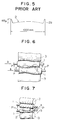
- Figs. 8 and 9 of the above-mentioned US-Patent discloses a rolling mill of the type in which an intermediate roll is interposed between each work roll and an associated backup roll and is axially shiftable together with the associated work roll in accordance with the width of the strip to be rolled.
- this type of rolling mill both the wear of the work rolls and thermal crown are uniformly distributed along the axes of the work rolls and the strip crown is also improved because the intermediate roll is shiftable.
- the construction of this type of rolling mill is complicated due to the addition of the shiftable intermediate rolls and the installation and running costs are raised accordingly.
- an object of the present invention is to provide a rolling method which makes use of a rolling mill having no intermediate roll between each work roll and the backup roll and which makes it possible to uniformly distribute the roll wear and the thermal crown, while improving the strip crown or edge drop.
- upstream stands work rolls in roll stands on the material inlet end of a tandem rolling mill
- downstream stands rolls on roll stands near the outlet end of the mill
- downstream stands are usually made of nickel grain and exhibit heavy wear.
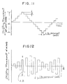
- Fig. 10 is a graph in which the axis of abscissa represents the No. of the roll stands, while the axis of ordinate represents the amount a of wear of work rolls in terms of roll diameter, copying coefficient ⁇ which represents the coefficient of copy of the roll wear to the rolled product, and the amount or height of step ( ⁇ x ⁇ ) formed on the work roll and to be transferred to the strip. From this figure, it will be understood that the height of step ( ⁇ x ⁇ ) greatly increases from the inlet end towards the outlet end of the rolling mill.
- the strip crown or edge drop is controlled so as to improve the strip crown or to eliminate edge drop in upstream stand or stands which suffers from only slight wear of work rolls, whereas, in the downstream roll stand or stands which suffer from heavy wear of work rolls, the work rolls are reciprocally and, preferably, cyclically moved in the axial direction regardless of the width of the material, thereby axially distributing the wear of the work rolls as well as thermal crown.
- the shifting movement of the work rolls of the downstream stage is always in counterdirection and is a setting movement before or after the rolling operation of a predetermined number of strips.
- the minimum and maximum lengths of the shifting movement (setting movement) before or after rolling of a predetermined number (from one to several) coils are about 20 mm (min) and about 400 mm (max), respectively, as indicated by A in Fig. 11, whereas the minium and maximum lengths of reciprocal movements of the downstream stage work rolls are 140 mm and 400 mm, respectively, as indicated by B in Fig. 11 and 12.
- a tandem rolling mill has seven roll stands F1 to F7 each of which has upper and lower work rolls 1 and backup rolls 3 which back up the respective work rolls.
- the upper and lower work rolls are axially shiftable in the opposite axial directions by means of work roll shifting means which is shown as being hydraulic cylinders 5 associated with the respective work rolls.
- work roll shifting means which is shown as being hydraulic cylinders 5 associated with the respective work rolls.
- the amount of shift of each work roll is indicated by ⁇ with a suffix representing the No. of the roll stand.
- the series of roll stands F1 to F7 are so constructed that roll bender forces P1 to P7 are exerted onto the work rolls so as to urge the work rolls away from each other by benders 6 which are indicated by double-headed arrows.
- the work roll shifting means 5 for axially displacing the work rolls and the roll bender 6 have been known and disclosed, for example, in the aforementioned US-A-3 857 268, so that detailed description thereof is omitted in this specification.
- work roll shifting means 5 associated with the first and the seventh roll stands F1 and F7 are shown, it will be obvious to those skilled in the art that similar work roll shifting means are provided also for other rolls stands F2 to F6.
- the rolling mill is equipped with a control unit 7 which is capable of controlling the amounts ⁇ of shift of the work rolls 1 as well as the roll bender forces P by the control of the work roll shifting means 5 and the roll benders 6 of all the roll stands F1 to F7 in accordance with rolling information concerning the rolling conditions such as the kind of the strip 2 to be rolled, temperature of the material, thicknesses and widths of the strips before and after the rolling and the rolling speed.
- the crown of the strip 2 delivered from the final roll stand F7 is detected by a crown detector 8 and the result is fed back to the control unit 7, whereby a desired crown is attained on the strip 2 rolled by the method of the present invention.
- a control unit 7 is well known to those skilled in the art, so that no further explanation will be needed.
- the series of roll stands of the tandem rolling mill is divided into two stages or groups: namely, an upstream stage adjacent to the inlet for the strip 2 and constituted by three upstream roll stands F1 to F3 and a downstream stage adjacent to the outlet for the strip 2 and constituted by four downstream roll stands F4 to F7.
- the roll stands F1 to F3 of the upstream stage conduct the rolling in accordance with the crown control mode
- the roll stands F4 to F7 of the downstream stage conduct the rolling in accordance with the roll profile control method.
- the upper and lower work rolls 1 are axially shifted in opposite directions in an amount according to the width of the strip 2 to positions optimum for the crown control rolling, as shown in Fig. 6.
- one end of the upper roll is positioned in the vicinity of the corresponding edge of the strip 2 while the end of the lower work roll opposite to the above-mentioned end is located in the vicinity of the other edge of the strip, as shown in Fig. 2.
- This control is effected by a crown control means 7a in the control unit 7 which sets the amount ⁇ 1 to ⁇ 3 of axial roll shifts in the respective roll stands F1 to F3 to be optimum for the control of the crown.
- a similar control can be effected for the cross mill shown in Fig. 7 in which the upper and lower work rolls in each roll stand are angularly movable in horizontal planes.
- the roll bender forces P1 to P3 applied by the roll benders 6 to the work rolls 1 in the respective roll stands F1 to F3 are controlled by the crown control means 7a such that bender forces optimum for the crown control are obtained in the respective roll stands.
- the work rolls 1 are reciprocally and cyclically moved in the axial direction, as shown in Fig. 2A. This reciprocal shift is conducted at predetermined intervals regardless of the widths of the strips 2.
- the roll bender forces P4 to P7 are set at levels which are optimum for the roll profile control.
- the control of the work roll shifting means 5 and the setting of the roll bender forces P4 to P7 in the respective stages F4 - F7 are performed by a roll profile control means 7b in the control unit 7.
- the profile, i.e., cross-sectional shape, of the rolled strip 2 is controlled and regulated by virtue of the crown control mode of rolling operation performed by the roll stands F1 to F3 of the upstream stage, whereas, in the roll stands F4 to F7 of the downstream stage, the roll wear and thermal crown are substantially uniformly distributed along the length of each work roll so as to eliminate any local concentration of wear because these roll stands F4 to F7 are operated in the cycle shift mode.
- a test operation was conducted using the 7-stand work roll shift type tandem rolling mill as shown in Figs. 1 to 2A.
- 140 pieces of strips of 1000 mm wide were continuously rolled by making use of this roll mill.
- the work rolls 1 of the roll stands F1 to F3 of the upstream stage were positioned as shown in Fig. 2 with respect to the strip 2, while the work rolls of the roll stands F4 to F7 of the downstream stage were cyclically shifted for each coil in accordance with the shift pattern which is shown in "Shift Pattern" of the "Case B" in Fig. 3.
- the profile of the strip produced by this test rolling is shown in Fig. 4 in a somewhat exaggerated manner.
- the state of wear caused on the work rolls 1 throughout the rolling process is shown in "Work Roll Wear Profile" of the "Case B" in Fig. 3.
- a comparison test was conducted for the purpose of evaluating the test result shown in Fig. 4.
- 140 pieces of strips 2 and width the same as those of the strips produced in the above-mentioned test operation were rolled by making use of a rolling mill of the same construction as that of the rolling mill shown in Figs. 1 and 2, with the work rolls 1 of the all stands F1 to F7 fixedly set at the optimum crown control positions shown in Fig. 2.
- the shift pattern of the work rolls 1 is as shown in "Shift Pattern" of the "Case A” in Fig. 3 because none of the work rolls 1 is shifted during the rolling operation.
- the state of wear caused on the work rolls 1 is shown in "Work Roll Wear Profile" of the "Case A” in Fig. 3.
- the profile of the rolled strip is shown in Fig. 5 in a somewhat exaggerated manner.
- the rolling by the roll stands F1 to F3 of the upstream stage of the rolling mill is conducted in accordance with the one-sided taper roll position control method, whereas, the roll stands F4 to F7 of the downstream stage are controlled in accordance with the roll profile control method.
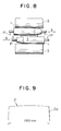
- the second embodiment of the rolling method in accordance with the invention employs roll stands of the type shown in Fig. 8. Throughout the rolling operation, the work rolls 1 of the roll stands F1 to F3 are fixedly held at positions optimum for the edge drop control as shown in Fig. 8, while the work rolls in the roll stands F4 to F7 are cyclically shifted.
- the strip 2 rolled through the roll stands F1 to F3 of the upstream stage exhibits such a thickness distribution that the thickness is greater at both side edge portions than at the mid portion of the strip.
- the strip having such a thickness distribution is then rolled through the roll stands F4 to F7 of the downstream stage, so that the final rolled strip exhibits a smaller edge drop at the edge portions 2a than in the case of the strip in accordance with the first embodiment of the method of the invention.
- a still further test rolling was conducted with a work roll shift mill having an upstream stage composed of three roll stands F1 to F3 of the type shown in Fig. 8 and a downstream stage composed of four roll stands F4 to F7 of the type shown in Fig. 2A.
- the roll stand shown in Fig. 8 is the same one as one disclosed in the JP-A-55-77903 referred to above.
- the upper work roll 1 is tapered at its one axial end (right end as viewed in Fig. 8) such that the diameter is progressively decreased towards the outer end extremity, while the lower work roll 1 is similarly tapered at its end which is on the left side as viewed in Fig. 8.
- the strip 2 was located with respect to these work rolls such that both edges of the strip 2 were registered with the adjacent tapered portions of the upper and lower work rolls 1.
- the roll stands F4 to F7 of the downstream stage of the mill were the same as those shown in Fig. 1.
- the work rolls of these stands were cyclically shifted in accordance with the shift pattern of the "Case B" in the Experimental Test 1.
- Rolling test was conducted in the same way as in the preceding test operations. The result is shown in Fig. 9.
- the rolling in accordance with the second embodiment of the present invention causes an edge drop which is much smaller than that caused by the first embodiment of the method of the present invention.
- the rolling method of the invention remarkably improves the strip crown or the edge drop as compared with those caused in the prior art rolling methods and provides substantially uniform distributions of roll wear and thermal crown in the axial direction of the work rolls. This enables the work rolls of the downstream stage to withstand a greatly increased number of rolling operations.
Landscapes
- Engineering & Computer Science (AREA)
- Mechanical Engineering (AREA)
- Control Of Metal Rolling (AREA)
- Metal Rolling (AREA)
Claims (8)
- Verfahren zum Walzen eines Metallbands in einem Tandemwalzwerk, das aufweist: wenigstens zwei Walzgerüste (F₁-F₇) mit oberen und unteren Stützwalzen (3) und horizontal einstellbaren oberen und unteren Arbeitswalzen (1), die mit Biegeeinrichtungen (6) zum Steuern der Planheit des Walzbands (2) ausgerüstet sind,
dadurch gekennzeichnet,
daß zum Steuern der Balligkeit und/oder des Kantenabfalls des Bands (2) die horizontale Verschiebung δ der Arbeitswalzen (1) und die auf diese Arbeitswalzen (1) wirkenden Biegekräfte (P) einer an der Aufstromseite befindlichen Gruppe (F₁-F₃) der Walzgerüste (F₁-F₇) nach Maßgabe der Walzbedingungen einschließlich der Breite der Bänder (2) eingestellt werden und
daß zum Steuern des Verschleißes und der thermischen Bombierung der Arbeitswalzen (1) in einer an der Abstromseite befindlichen Gruppe (F₄-F₇) der Walzgerüste diese Arbeitswalzen (1) in vorbestimmten Intervallen ungeachtet der Breite des Bands (2) hin- und herverschoben werden. - Walzverfahren nach Anspruch 1,
dadurch gekennzeichnet,
daß die Arbeitswalzen (1) der Walzgerüste (F₁-F₇) in der an der Abstromseite befindlichen Gruppe (F₄-F₇) vor oder nach einer vorbestimmten Zahl von Durchgängen des Bands (2) in die axial entgegengesetzte Richtung zyklisch verschoben werden. - Walzverfahren nach Anspruch 1 oder 2,
dadurch gekennzeichnet,
daß die Arbeitswalzen (1) der Walzgerüste (F₁-F₇) in der an der Aufstromseite befindlichen Gruppe (F₁-F₃) vor dem Beginn der Walzbetriebs in den axial entgegengesetzten Richtungen in einer vorbestimmten Lage fest eingestellt werden. - Walzverfahren nach Anspruch 1 oder 2,
dadurch gekennzeichnet,
daß die Arbeitswalzen (1) der Walzgerüste (F₁-F₇) in der an der Aufstromseite befindlichen Gruppe (F₁-F₃) winkelmäßig eingestellt werden. - Tandemwalzwerk, das aufweist: eine Vielzahl von Walzgerüsten (F₁-F₇), die jeweils obere und untere Stützwalzen (3), obere und untere Arbeitswalzen (1), Einrichtungen (5) zum Verschieben der Arbeitswalzen (1) in Horizontalrichtungen, Einrichtungen (6) zum Biegen der Arbeitswalzen (1) und eine Steuereinheit (7), die mit einem Bandplanheitsdetektor (8) verbunden ist, um die Verschiebung δ und die Biegekraft (P) der Arbeitswalzen (1) in den Walzgerüsten (F₁-F₇) zu steuern,
dadurch gekennzeichnet,
daß die Steuereinheit (7) aufweist:- eine Bandballigkeits-Steuereinrichtung (7a) zum Einstellen der Verschiebung δ₁ bis δ₃ und der Biegekraft (P₁-P₃) der Arbeitswalzen (1) in einer an der Aufstromseite befindlichen Gruppe (F₁-F₃) der Walzgerüste (F₁-F₇) nach Maßgabe der Walzbedingungen einschließlich der Breiten des Bands (2) und- eine Arbeitswalzen-Profilsteuereinrichtung (7b) zum Hinund Herverschieben der oberen und unteren zylindrischen Arbeitswalzen (1) einer an der Abstromseite befindlichen Gruppe (F₄-F₇) der Walzgerüste (F₁-F₇) in axialen Richtungen ungeachtet der Breite des Bands (2). - Walzwerk nach Anspruch 5,
dadurch gekennzeichnet,
daß die Arbeitswalzen (1) der an der Aufstromseite befindlichen Gruppe (F₁-F₃) der Walzgerüste (F₁-F₇)) konisch verjüngte Endteile haben und in Axialrichtung bewegbar sind und daß die Bandballigkeits-Steuereinrichtung (7b) die axiale Verschiebung δ₁ bis δ₃ dieser Arbeitswalzen (1) so einstellt, daß beide Kanten des Bands (2) in Deckung mit den angrenzenden konisch verjüngten Endteilen der oberen und unteren Arbeitswalzen (1) gebracht werden. - Walzwerk nach Anspruch 5,
dadurch gekennzeichnet,
daß die Arbeitswalzen (1) der an der Aufstromseite befindlichen Gruppe (F₁-F₃) der Walzgerüste (F₁-F₇) durch die Einwirkung der Bandballigkeits-Steuereinrichtung (7b) in einer horizontalen Ebene winkelmäßig einstellbar sind. - Walzwerk nach Anspruch 5,
dadurch gekennzeichnet,
daß die Arbeitswalzen (1) der an der Aufstromseite befindlichen Gruppe (F₁-F₃) der Walzgerüste (F₁-F₇)) mit im wesentlichen S-förmigen Profilen versehen sind, die durch zueinander in bezug auf einen Punkt symmetrische Kurven definiert sind, und in Axialrichtung relativ zueinander durch die Einwirkung der Bandballigkeits-Steuereinrichtung (7b) bewegbar sind.
Applications Claiming Priority (2)
| Application Number | Priority Date | Filing Date | Title |
|---|---|---|---|
| JP62014461A JP2616917B2 (ja) | 1987-01-24 | 1987-01-24 | ロールシフト圧延機による圧延方法 |
| JP14461/87 | 1987-01-24 |
Publications (2)
| Publication Number | Publication Date |
|---|---|
| EP0276743A1 EP0276743A1 (de) | 1988-08-03 |
| EP0276743B1 true EP0276743B1 (de) | 1992-07-29 |
Family
ID=11861688
Family Applications (1)
| Application Number | Title | Priority Date | Filing Date |
|---|---|---|---|
| EP88100774A Expired - Lifetime EP0276743B1 (de) | 1987-01-24 | 1988-01-20 | Metallwalzverfahren mit in Axialrichtung verschiebbaren Arbeitswalzen |
Country Status (5)
| Country | Link |
|---|---|
| US (1) | US4864836A (de) |
| EP (1) | EP0276743B1 (de) |
| JP (1) | JP2616917B2 (de) |
| KR (1) | KR950009910B1 (de) |
| DE (1) | DE3873103T2 (de) |
Cited By (12)
| Publication number | Priority date | Publication date | Assignee | Title |
|---|---|---|---|---|
| EP0555882A1 (de) * | 1992-02-14 | 1993-08-18 | Hitachi, Ltd. | Tandemwalzsystem und Walzenschrägwalzwerk |
| EP0618020A1 (de) * | 1993-03-29 | 1994-10-05 | Sms Schloemann-Siemag Aktiengesellschaft | Verfahren und Vorrichtung zum Walzen eines Walzbandes |
| DE19719318A1 (de) * | 1997-05-08 | 1998-11-12 | Schloemann Siemag Ag | Verfahren zur Beeinflussung der Bandkontur im Kantenbereich eines Walzenbandes |
| US5875663A (en) * | 1996-07-18 | 1999-03-02 | Kawasaki Steel Corporation | Rolling method and rolling mill of strip for reducing edge drop |
| US5970765A (en) * | 1996-12-23 | 1999-10-26 | Sms Schloemann-Siemag Aktiengesellschaft | Method and apparatus for rolling strip |
| EP0953384A2 (de) | 1998-04-29 | 1999-11-03 | Voest-Alpine Industrieanlagenbau Gmbh | Verfahren zur Verbesserung der Kontur gewalzten Materials und zur Erhöhung der gewalzten Materiallänge |
| RU2210446C2 (ru) * | 2001-11-01 | 2003-08-20 | Открытое акционерное общество "Новолипецкий металлургический комбинат" | Способ производства полос |
| DE4424613B4 (de) * | 1994-07-13 | 2007-03-29 | Sms Demag Ag | Verfahren zum Betreiben eines Walzgerüstes |
| DE102006051728A1 (de) * | 2006-10-30 | 2008-05-08 | Thyssenkrupp Nirosta Gmbh | Verfahren und Walzen von Metallbändern, inbesondere von Stahlbändern |
| EP1228818B2 (de) † | 2001-02-05 | 2015-09-09 | Hitachi Ltd. | Walzverfahren für Bandwalzwerk und Bandwalzeinrichtung |
| EP3600708B1 (de) | 2017-03-31 | 2022-06-01 | Clecim Sas | Walzgerüst, das mit einer kontrollvorrichtung für die walzstabilität ausgerüstet ist, und entsprechende methode |
| EP3917694B1 (de) | 2019-01-28 | 2023-08-09 | Primetals Technologies Germany GmbH | Verändern der effektiven kontur einer lauffläche einer arbeitswalze während des warmwalzens eines walzguts in einem walzgerüst zu einem gewalzten band |
Families Citing this family (20)
| Publication number | Priority date | Publication date | Assignee | Title |
|---|---|---|---|---|
| US5231858A (en) * | 1990-11-30 | 1993-08-03 | Kawasaki Steel Corporation | Method of controlling edge drop in cold rolling of steel |
| JP3060691B2 (ja) * | 1991-03-29 | 2000-07-10 | 株式会社日立製作所 | 圧延機及び熱間圧延設備及び圧延方法及び圧延機の改造方法 |
| KR960010237B1 (ko) * | 1992-08-07 | 1996-07-26 | 가와사끼 세이데쓰 가부시끼가이샤 | 엔드리스 열간압연방법 |
| JP3254067B2 (ja) * | 1993-05-07 | 2002-02-04 | 川崎製鉄株式会社 | エンドレス圧延における板クラウンの制御方法 |
| US5782121A (en) * | 1993-07-16 | 1998-07-21 | Schumag Ag | Apparatus for the inner profiling of tubes or pipes |
| DE4323840A1 (de) * | 1993-07-16 | 1995-01-19 | Schumag Ag | Verfahren zur Innenprofilierung von Rohren und Einrichtung zur Durchführung des Verfahrens |
| DE4409299A1 (de) * | 1994-03-18 | 1995-09-21 | Schloemann Siemag Ag | Verfahren und Vorrichtung zum Walzen von Bändern |
| JP3826974B2 (ja) * | 1997-05-29 | 2006-09-27 | 石川島播磨重工業株式会社 | 熱間タンデム圧延機 |
| US5970771A (en) * | 1998-07-10 | 1999-10-26 | Danieli United | Continuous spiral motion system for rolling mills |
| JP2933923B1 (ja) * | 1998-09-08 | 1999-08-16 | 川崎重工業株式会社 | 薄板の熱間圧延機 |
| JP2004148377A (ja) * | 2002-10-31 | 2004-05-27 | Jfe Steel Kk | 仕上圧延方法 |
| JP4273454B2 (ja) * | 2003-06-27 | 2009-06-03 | 株式会社Ihi | 板圧延用シフトロールの形状決定方法 |
| JP2005052864A (ja) * | 2003-08-04 | 2005-03-03 | Ishikawajima Harima Heavy Ind Co Ltd | 帯板製造設備 |
| US20050275160A1 (en) * | 2004-06-07 | 2005-12-15 | Reslow Leif F | Transport assembly with driven split nip rollers |
| DE102004031354A1 (de) | 2004-06-28 | 2006-01-19 | Sms Demag Ag | Verfahren zum Walzen von Bändern in einem Walzgerüst |
| CN103447312B (zh) * | 2013-09-03 | 2015-08-12 | 首钢京唐钢铁联合有限责任公司 | 一种热轧板板型的控制方法 |
| CN205659983U (zh) * | 2016-06-15 | 2016-10-26 | 日照宝华新材料有限公司 | 一种esp生产线用长公里数轧制辊 |
| CN115968325A (zh) * | 2020-09-10 | 2023-04-14 | 杰富意钢铁株式会社 | 冷轧方法、冷轧设备以及冷轧钢板的制造方法 |
| CN113263060B (zh) * | 2021-04-25 | 2023-01-20 | 北京科技大学设计研究院有限公司 | 改善带钢局部凸起提升工作辊轧制公里数的窜辊控制方法 |
| CN118616502B (zh) * | 2023-03-08 | 2025-11-04 | 上海梅山钢铁股份有限公司 | 一种延长轧机轧制公里数的板形控制方法 |
Family Cites Families (12)
| Publication number | Priority date | Publication date | Assignee | Title |
|---|---|---|---|---|
| JPS517635B2 (de) * | 1971-12-10 | 1976-03-09 | ||
| JPS6051921B2 (ja) * | 1978-12-08 | 1985-11-16 | 川崎製鉄株式会社 | 形状制御圧延方法 |
| CA1174084A (en) * | 1980-08-08 | 1984-09-11 | Takeshi Masui | Tandem mill |
| DE3245090A1 (de) * | 1982-12-06 | 1984-06-07 | SMS Schloemann-Siemag AG, 4000 Düsseldorf | Verfahren und einrichtung zum walzen von metallbaendern |
| JPS59110401A (ja) * | 1982-12-14 | 1984-06-26 | Ishikawajima Harima Heavy Ind Co Ltd | 圧延方法 |
| JPS59225803A (ja) * | 1983-06-06 | 1984-12-18 | Hitachi Ltd | 圧延方法 |
| EP0153849B1 (de) * | 1984-02-29 | 1992-01-15 | Kawasaki Steel Corporation | Warmwalzverfahren |
| JPS6192704A (ja) * | 1984-10-11 | 1986-05-10 | Nippon Steel Corp | 圧延機群 |
| JPS61126904A (ja) * | 1984-11-24 | 1986-06-14 | Kawasaki Steel Corp | 帯板の圧延方法 |
| JPS61154709A (ja) * | 1984-12-26 | 1986-07-14 | Kawasaki Steel Corp | 板材の厚さプロフイル制御装置 |
| JPS61193714A (ja) * | 1985-02-22 | 1986-08-28 | Nippon Steel Corp | 板圧延におけるウエツジ制御法 |
| US4730475A (en) * | 1986-05-06 | 1988-03-15 | International Rolling Mills Consultants, Inc. | Rolling mill method |
-
1987
- 1987-01-24 JP JP62014461A patent/JP2616917B2/ja not_active Expired - Lifetime
-
1988
- 1988-01-13 US US07/143,199 patent/US4864836A/en not_active Expired - Lifetime
- 1988-01-20 EP EP88100774A patent/EP0276743B1/de not_active Expired - Lifetime
- 1988-01-20 DE DE8888100774T patent/DE3873103T2/de not_active Revoked
- 1988-01-22 KR KR1019880000490A patent/KR950009910B1/ko not_active Expired - Fee Related
Cited By (21)
| Publication number | Priority date | Publication date | Assignee | Title |
|---|---|---|---|---|
| US5657655A (en) * | 1992-02-14 | 1997-08-19 | Hitachi, Ltd. | Tandem mill system and work roll crossing mill |
| EP0555882A1 (de) * | 1992-02-14 | 1993-08-18 | Hitachi, Ltd. | Tandemwalzsystem und Walzenschrägwalzwerk |
| EP0618020A1 (de) * | 1993-03-29 | 1994-10-05 | Sms Schloemann-Siemag Aktiengesellschaft | Verfahren und Vorrichtung zum Walzen eines Walzbandes |
| DE4424613B4 (de) * | 1994-07-13 | 2007-03-29 | Sms Demag Ag | Verfahren zum Betreiben eines Walzgerüstes |
| US5875663A (en) * | 1996-07-18 | 1999-03-02 | Kawasaki Steel Corporation | Rolling method and rolling mill of strip for reducing edge drop |
| RU2203154C2 (ru) * | 1996-12-23 | 2003-04-27 | Смс Шлёманн-Зимаг Аг | Способ прокатки ленты и устройство для его осуществления |
| US5970765A (en) * | 1996-12-23 | 1999-10-26 | Sms Schloemann-Siemag Aktiengesellschaft | Method and apparatus for rolling strip |
| DE19719318C2 (de) * | 1997-05-08 | 2003-06-12 | Sms Demag Ag | Verfahren zur Beeinflussung der Bandkontur im Kantenbereich eines Walzenbandes |
| US5943896A (en) * | 1997-05-08 | 1999-08-31 | Sms Schloemann-Siemag Aktiengesellschaft | Method of influencing the strip contour in the edge region of a rolled strip |
| DE19719318A1 (de) * | 1997-05-08 | 1998-11-12 | Schloemann Siemag Ag | Verfahren zur Beeinflussung der Bandkontur im Kantenbereich eines Walzenbandes |
| EP0953384A2 (de) | 1998-04-29 | 1999-11-03 | Voest-Alpine Industrieanlagenbau Gmbh | Verfahren zur Verbesserung der Kontur gewalzten Materials und zur Erhöhung der gewalzten Materiallänge |
| US6164103A (en) * | 1998-04-29 | 2000-12-26 | Voest-Alpine Industrieanlagenbau Gmbh | Method for improving the contour of rolled material |
| EP1228818B2 (de) † | 2001-02-05 | 2015-09-09 | Hitachi Ltd. | Walzverfahren für Bandwalzwerk und Bandwalzeinrichtung |
| RU2210446C2 (ru) * | 2001-11-01 | 2003-08-20 | Открытое акционерное общество "Новолипецкий металлургический комбинат" | Способ производства полос |
| WO2008052939A1 (de) * | 2006-10-30 | 2008-05-08 | Thyssenkrupp Nirosta Gmbh | Verfahren zum walzen von metallbändern, insbesondere von stahlbändern |
| DE102006051728B4 (de) * | 2006-10-30 | 2013-11-21 | Outokumpu Nirosta Gmbh | Verfahren zum Walzen von Metallbändern, inbesondere von Stahlbändern |
| US8627702B2 (en) | 2006-10-30 | 2014-01-14 | Outokumu Nirosta GmbH | Method for rolling metal strips, particularly steel strips |
| DE102006051728A1 (de) * | 2006-10-30 | 2008-05-08 | Thyssenkrupp Nirosta Gmbh | Verfahren und Walzen von Metallbändern, inbesondere von Stahlbändern |
| EP3600708B1 (de) | 2017-03-31 | 2022-06-01 | Clecim Sas | Walzgerüst, das mit einer kontrollvorrichtung für die walzstabilität ausgerüstet ist, und entsprechende methode |
| EP3917694B1 (de) | 2019-01-28 | 2023-08-09 | Primetals Technologies Germany GmbH | Verändern der effektiven kontur einer lauffläche einer arbeitswalze während des warmwalzens eines walzguts in einem walzgerüst zu einem gewalzten band |
| US12285790B2 (en) | 2019-01-28 | 2025-04-29 | Primetals Technologies Germany Gmbh | Changing the effective contour of a running surface of a working roll during hot rolling of rolling stock in a roll stand to form a rolled strip |
Also Published As
| Publication number | Publication date |
|---|---|
| DE3873103D1 (de) | 1992-09-03 |
| JP2616917B2 (ja) | 1997-06-04 |
| JPS63183703A (ja) | 1988-07-29 |
| US4864836A (en) | 1989-09-12 |
| KR880008842A (ko) | 1988-09-13 |
| KR950009910B1 (ko) | 1995-09-01 |
| DE3873103T2 (de) | 1993-02-25 |
| EP0276743A1 (de) | 1988-08-03 |
Similar Documents
| Publication | Publication Date | Title |
|---|---|---|
| EP0276743B1 (de) | Metallwalzverfahren mit in Axialrichtung verschiebbaren Arbeitswalzen | |
| EP1230991B1 (de) | Tandemwalzwerksanlage und Walzverfahren unter Verwendung derselben | |
| EP0628361B2 (de) | Verfahren zur Blechballigkeitsregelung und Anlage für endloses Walzen | |
| GB2079205A (en) | Tandem rolling mill train for metal plate and sheet | |
| EP1033182A1 (de) | Warmbandwalzwerk | |
| CN1976768B (zh) | 在轧机机座里对钢带进行轧制的方法 | |
| CA1174084A (en) | Tandem mill | |
| JPH0275403A (ja) | 冷間圧延法と圧延ロール | |
| JP2000102806A (ja) | 圧延機 | |
| JPH0620562B2 (ja) | 熱間圧延時の板クラウン制御方法 | |
| JP2569017B2 (ja) | ワ−クロ−ル移動式圧延機による板材の圧延方法 | |
| JP3587579B2 (ja) | タンデム冷間圧延機における金属帯のプロフィール制御方法 | |
| JP3317311B2 (ja) | ロールシフト式圧延機用ロールとこれを用いた圧延機 | |
| JP2585608B2 (ja) | テンシヨンロ−ラレベラ | |
| JPH0275404A (ja) | 形材のウエブ厚み圧下用ロール | |
| JPS62263805A (ja) | 圧延ロール及び圧延方法 | |
| CA1302743C (en) | Method of controlling strip crown in planetary rolling | |
| JP2000051914A (ja) | 板材圧延における板幅制御方法 | |
| JPS635812A (ja) | ワ−クロ−ル移動式圧延機による板材の圧延方法 | |
| JP3167440B2 (ja) | エンドレス圧延方法 | |
| JPH02112801A (ja) | フランジ付き形鋼のユニバーサル圧延方法と圧延機 | |
| JPS63268502A (ja) | 極薄金属帯の製造方法 | |
| JPH067876A (ja) | 異形横断面形状を有する帯・板材の製造方法 | |
| JPH02133102A (ja) | 溝形材および類似形材の圧延方法およびその装置 | |
| JPH06154805A (ja) | 熱間圧延方法 |
Legal Events
| Date | Code | Title | Description |
|---|---|---|---|
| PUAI | Public reference made under article 153(3) epc to a published international application that has entered the european phase |
Free format text: ORIGINAL CODE: 0009012 |
|
| AK | Designated contracting states |
Kind code of ref document: A1 Designated state(s): DE FR GB IT |
|
| 17P | Request for examination filed |
Effective date: 19880808 |
|
| 17Q | First examination report despatched |
Effective date: 19900710 |
|
| GRAA | (expected) grant |
Free format text: ORIGINAL CODE: 0009210 |
|
| AK | Designated contracting states |
Kind code of ref document: B1 Designated state(s): DE FR GB IT |
|
| REF | Corresponds to: |
Ref document number: 3873103 Country of ref document: DE Date of ref document: 19920903 |
|
| ET | Fr: translation filed | ||
| ITF | It: translation for a ep patent filed | ||
| PLBI | Opposition filed |
Free format text: ORIGINAL CODE: 0009260 |
|
| 26 | Opposition filed |
Opponent name: SMS SCHLOEMANN-SIEMAG AG Effective date: 19930429 |
|
| PGFP | Annual fee paid to national office [announced via postgrant information from national office to epo] |
Ref country code: FR Payment date: 19951221 Year of fee payment: 9 |
|
| PGFP | Annual fee paid to national office [announced via postgrant information from national office to epo] |
Ref country code: GB Payment date: 19951227 Year of fee payment: 9 |
|
| PGFP | Annual fee paid to national office [announced via postgrant information from national office to epo] |
Ref country code: DE Payment date: 19960329 Year of fee payment: 9 |
|
| APAC | Appeal dossier modified |
Free format text: ORIGINAL CODE: EPIDOS NOAPO |
|
| RDAG | Patent revoked |
Free format text: ORIGINAL CODE: 0009271 |
|
| STAA | Information on the status of an ep patent application or granted ep patent |
Free format text: STATUS: PATENT REVOKED |
|
| GBPR | Gb: patent revoked under art. 102 of the ep convention designating the uk as contracting state |
Free format text: 960625 |
|
| 27W | Patent revoked |
Effective date: 19960625 |
|
| APAH | Appeal reference modified |
Free format text: ORIGINAL CODE: EPIDOSCREFNO |