EP0276743B1 - Rolling method making use of work roll shift rolling mill - Google Patents
Rolling method making use of work roll shift rolling mill Download PDFInfo
- Publication number
- EP0276743B1 EP0276743B1 EP88100774A EP88100774A EP0276743B1 EP 0276743 B1 EP0276743 B1 EP 0276743B1 EP 88100774 A EP88100774 A EP 88100774A EP 88100774 A EP88100774 A EP 88100774A EP 0276743 B1 EP0276743 B1 EP 0276743B1
- Authority
- EP
- European Patent Office
- Prior art keywords
- work rolls
- strip
- roll
- rolling
- roll stands
- Prior art date
- Legal status (The legal status is an assumption and is not a legal conclusion. Google has not performed a legal analysis and makes no representation as to the accuracy of the status listed.)
- Expired - Lifetime
Links
Images


Classifications
-
- B—PERFORMING OPERATIONS; TRANSPORTING
- B21—MECHANICAL METAL-WORKING WITHOUT ESSENTIALLY REMOVING MATERIAL; PUNCHING METAL
- B21B—ROLLING OF METAL
- B21B13/00—Metal-rolling stands, i.e. an assembly composed of a stand frame, rolls, and accessories
- B21B13/18—Metal-rolling stands, i.e. an assembly composed of a stand frame, rolls, and accessories for step-by-step or planetary rolling; pendulum mills
-
- B—PERFORMING OPERATIONS; TRANSPORTING
- B21—MECHANICAL METAL-WORKING WITHOUT ESSENTIALLY REMOVING MATERIAL; PUNCHING METAL
- B21B—ROLLING OF METAL
- B21B37/00—Control devices or methods specially adapted for metal-rolling mills or the work produced thereby
- B21B37/28—Control of flatness or profile during rolling of strip, sheets or plates
- B21B37/42—Control of flatness or profile during rolling of strip, sheets or plates using a combination of roll bending and axial shifting of the rolls
-
- B—PERFORMING OPERATIONS; TRANSPORTING
- B21—MECHANICAL METAL-WORKING WITHOUT ESSENTIALLY REMOVING MATERIAL; PUNCHING METAL
- B21B—ROLLING OF METAL
- B21B1/00—Metal-rolling methods or mills for making semi-finished products of solid or profiled cross-section; Sequence of operations in milling trains; Layout of rolling-mill plant, e.g. grouping of stands; Succession of passes or of sectional pass alternations
- B21B1/22—Metal-rolling methods or mills for making semi-finished products of solid or profiled cross-section; Sequence of operations in milling trains; Layout of rolling-mill plant, e.g. grouping of stands; Succession of passes or of sectional pass alternations for rolling plates, strips, bands or sheets of indefinite length
- B21B1/24—Metal-rolling methods or mills for making semi-finished products of solid or profiled cross-section; Sequence of operations in milling trains; Layout of rolling-mill plant, e.g. grouping of stands; Succession of passes or of sectional pass alternations for rolling plates, strips, bands or sheets of indefinite length in a continuous or semi-continuous process
-
- B—PERFORMING OPERATIONS; TRANSPORTING
- B21—MECHANICAL METAL-WORKING WITHOUT ESSENTIALLY REMOVING MATERIAL; PUNCHING METAL
- B21B—ROLLING OF METAL
- B21B13/00—Metal-rolling stands, i.e. an assembly composed of a stand frame, rolls, and accessories
- B21B13/02—Metal-rolling stands, i.e. an assembly composed of a stand frame, rolls, and accessories with axes of rolls arranged horizontally
- B21B13/023—Metal-rolling stands, i.e. an assembly composed of a stand frame, rolls, and accessories with axes of rolls arranged horizontally the axis of the rolls being other than perpendicular to the direction of movement of the product, e.g. cross-rolling
-
- B—PERFORMING OPERATIONS; TRANSPORTING
- B21—MECHANICAL METAL-WORKING WITHOUT ESSENTIALLY REMOVING MATERIAL; PUNCHING METAL
- B21B—ROLLING OF METAL
- B21B13/00—Metal-rolling stands, i.e. an assembly composed of a stand frame, rolls, and accessories
- B21B13/14—Metal-rolling stands, i.e. an assembly composed of a stand frame, rolls, and accessories having counter-pressure devices acting on rolls to inhibit deflection of same under load; Back-up rolls
- B21B13/142—Metal-rolling stands, i.e. an assembly composed of a stand frame, rolls, and accessories having counter-pressure devices acting on rolls to inhibit deflection of same under load; Back-up rolls by axially shifting the rolls, e.g. rolls with tapered ends or with a curved contour for continuously-variable crown CVC
-
- B—PERFORMING OPERATIONS; TRANSPORTING
- B21—MECHANICAL METAL-WORKING WITHOUT ESSENTIALLY REMOVING MATERIAL; PUNCHING METAL
- B21B—ROLLING OF METAL
- B21B2263/00—Shape of product
- B21B2263/02—Profile, e.g. of plate, hot strip, sections
-
- B—PERFORMING OPERATIONS; TRANSPORTING
- B21—MECHANICAL METAL-WORKING WITHOUT ESSENTIALLY REMOVING MATERIAL; PUNCHING METAL
- B21B—ROLLING OF METAL
- B21B2267/00—Roll parameters
- B21B2267/18—Roll crown; roll profile
- B21B2267/19—Thermal crown
-
- B—PERFORMING OPERATIONS; TRANSPORTING
- B21—MECHANICAL METAL-WORKING WITHOUT ESSENTIALLY REMOVING MATERIAL; PUNCHING METAL
- B21B—ROLLING OF METAL
- B21B2267/00—Roll parameters
- B21B2267/24—Roll wear
-
- B—PERFORMING OPERATIONS; TRANSPORTING
- B21—MECHANICAL METAL-WORKING WITHOUT ESSENTIALLY REMOVING MATERIAL; PUNCHING METAL
- B21B—ROLLING OF METAL
- B21B2269/00—Roll bending or shifting
- B21B2269/02—Roll bending; vertical bending of rolls
- B21B2269/04—Work roll bending
-
- B—PERFORMING OPERATIONS; TRANSPORTING
- B21—MECHANICAL METAL-WORKING WITHOUT ESSENTIALLY REMOVING MATERIAL; PUNCHING METAL
- B21B—ROLLING OF METAL
- B21B2269/00—Roll bending or shifting
- B21B2269/12—Axial shifting the rolls
- B21B2269/14—Work rolls
Description
- The invention relates to a method for rolling a metal strip in a tandem rolling mill according to the first portion of
claim 1 and to a tandem rolling mill for using that method. - The US-A 3,857,268 discloses in Fig. 2 a tandem roll mill in which upper and lower work rolls of each stand are shiftable in the axial direction of these rolls so as to vary the axial length over which each work roll and an associated backup roll contact with each other, thereby effecting crown control of a rolled strip.
- The JP-A 55-77903 discloses a rolling mill in which one of upper and lower work rolls is tapered at its one axial end such that the diameter is progressively reduced towards the outer end extremity, while the other of the work rolls is similarly tapered at its end opposite to the tapered end of the first-mentioned work roll. In operation, the strip to be rolled and the work rolls are located relative to each other such that the both side edges of the strip are positioned in the vicinities of the tapered ends of the work rolls, thereby reducing the tendency of occurrence of edge drop. The rolling method which makes use of this type of rolling mill will be referred to as one-sided taper roll position control method.
- The JP-A 55-77903 discloses a pair roll cross rolling mill in which each of upper and lower work rolls together with its associated backup roll is angularly movable in a horizontal plane so that the angle formed between the axes of both work rolls is controllable. The JP-A 56-30014 discloses a rolling mill in which upper and lower work rolls of each stand are provided with point-symmetric profiles such as S-shaped or sine-curve-shaped profiles and are axially movable relative to each other. These two types of rolling mills have both been developed for the purpose of control of the strip crown.
- A method called as "cycle-shift method" has been reported in HITACHI REVIEW, Vol. 34, No. 4, August 1985. In this method, work rolls are cyclically shifted in the axial direction so as to uniformly distribute any roll wear and thermal crown in the axial direction. This method, when applied to rolling of strips by any of the roll mills shown in Fig. 2 of the above-mentioned US-Patent and the three JP-Publications, is not suited to axially uniformly distribute the roll wear and thermal crown, although the control of strip crown or edge drop can be achieved appreciably well.
- Figs. 8 and 9 of the above-mentioned US-Patent discloses a rolling mill of the type in which an intermediate roll is interposed between each work roll and an associated backup roll and is axially shiftable together with the associated work roll in accordance with the width of the strip to be rolled. When the above-mentioned cycle shift method is carried out with this type of rolling mill, both the wear of the work rolls and thermal crown are uniformly distributed along the axes of the work rolls and the strip crown is also improved because the intermediate roll is shiftable. Unfortunately, however, the construction of this type of rolling mill is complicated due to the addition of the shiftable intermediate rolls and the installation and running costs are raised accordingly.
- Accordingly, an object of the present invention is to provide a rolling method which makes use of a rolling mill having no intermediate roll between each work roll and the backup roll and which makes it possible to uniformly distribute the roll wear and the thermal crown, while improving the strip crown or edge drop. This object will be solved by the features of the
claim 1. - In general, work rolls in roll stands on the material inlet end of a tandem rolling mill (such stands will be referred to as "upstream stands") are made of adamite or High-chromium. As a result of contact with the material at a high temperature, the surfaces of these rolls are oxidized to form oxide films, so that the wear is to a very small extent on these rolls. On the other hands, rolls on roll stands near the outlet end of the mill (such stands will be referred to as "downstream stands") are usually made of nickel grain and exhibit heavy wear.
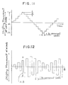
- This fact will be more clearly seen in Fig. 10 which is a graph in which the axis of abscissa represents the No. of the roll stands, while the axis of ordinate represents the amount a of wear of work rolls in terms of roll diameter, copying coefficient β which represents the coefficient of copy of the roll wear to the rolled product, and the amount or height of step (α x β) formed on the work roll and to be transferred to the strip. From this figure, it will be understood that the height of step (α x β) greatly increases from the inlet end towards the outlet end of the rolling mill.
- In view of the above facts, according to the rolling method of the present invention which makes use of a tandem rolling mill, the strip crown or edge drop is controlled so as to improve the strip crown or to eliminate edge drop in upstream stand or stands which suffers from only slight wear of work rolls, whereas, in the downstream roll stand or stands which suffer from heavy wear of work rolls, the work rolls are reciprocally and, preferably, cyclically moved in the axial direction regardless of the width of the material, thereby axially distributing the wear of the work rolls as well as thermal crown.
- With advantage, the shifting movement of the work rolls of the downstream stage is always in counterdirection and is a setting movement before or after the rolling operation of a predetermined number of strips. In praxis, the minimum and maximum lengths of the shifting movement (setting movement) before or after rolling of a predetermined number (from one to several) coils are about 20 mm (min) and about 400 mm (max), respectively, as indicated by A in Fig. 11, whereas the minium and maximum lengths of reciprocal movements of the downstream stage work rolls are 140 mm and 400 mm, respectively, as indicated by B in Fig. 11 and 12.
- The above and other objects, features and advantages of the present invention will become more clear from the following description of preferred embodiments with reference to the accompanying drawings.
-
- Fig. 1 is a schematic illustration of a tandem rolling mill and a controlling system suitable for use in carrying out the rolling method of the present invention.
- Fig. 2 is a schematic front elevational view of an example of arrangement of work rolls and backup rolls in one of a plurality of upstream roll stands of the tandem rolling mill shown in Fig. 1;
- Figs. 2A and 2B are similar to Fig. 2 but show work rolls and backup rolls in a downstream roll stand of the rolling mill shown in Fig. 1;
- Fig. 3 is a diagram illustrating work roll local wear and work roll wear profile in relation to Case A (work rolls are not shifted pattern both in crown control and Case B (roll profile is controlled);
- Fig. 4 is a somewhat exaggerated illustration of the profile of a strip rolled in accordance with a first embodiment of the method of the present invention;
- Fig. 5 is a somewhat exaggerated illustration of the profile of a strip rolled without cycle shift method;
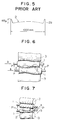
- Fig. 6 is a schematic front elevational view of another example of the work rolls and backup rolls in an upstream roll stand of the tandem rolling mill shown in Fig 1;
- Fig. 7 is a schematic perspective view of a still another example of the work rolls and backup rolls in an upstream roll stand of the tandem rolling mill shown in Fig. 1;
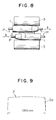
- Fig. 8 is a schematic front elevational view of work rolls and backup rolls in an upstream roll stand of the tandem rolling mill shown in Fig. 1 used in carrying out a second embodiment of the method in accordance with the present invention;
- Fig. 9 is a somewhat exaggerated illustration of a strip profile of a strip rolled in accordance with the second embodiment of the method of the present invention; and
- Fig. 10 is a graph showing the relationship between roll wear in terms of roll diameter, coefficient of copy of roll wear to strip and stepped roll wear to be copied to the strip in each of roll stands.
- Fig. 11 and 12 are graphs of the shifting movements of the workrolls of the downstream stage.
- Referring to Fig. 1, a tandem rolling mill has seven roll stands F1 to F7 each of which has upper and
lower work rolls 1 andbackup rolls 3 which back up the respective work rolls. In each of the roll stands F1 to F7, the upper and lower work rolls are axially shiftable in the opposite axial directions by means of work roll shifting means which is shown as beinghydraulic cylinders 5 associated with the respective work rolls. The amount of shift of each work roll is indicated by δ with a suffix representing the No. of the roll stand. The series of roll stands F1 to F7 are so constructed that roll bender forces P1 to P7 are exerted onto the work rolls so as to urge the work rolls away from each other bybenders 6 which are indicated by double-headed arrows. The work roll shifting means 5 for axially displacing the work rolls and theroll bender 6 have been known and disclosed, for example, in the aforementioned US-A-3 857 268, so that detailed description thereof is omitted in this specification. Although work roll shifting means 5 associated with the first and the seventh roll stands F1 and F7 are shown, it will be obvious to those skilled in the art that similar work roll shifting means are provided also for other rolls stands F2 to F6. - The rolling mill is equipped with a
control unit 7 which is capable of controlling the amounts δ of shift of thework rolls 1 as well as the roll bender forces P by the control of the work roll shifting means 5 and theroll benders 6 of all the roll stands F1 to F7 in accordance with rolling information concerning the rolling conditions such as the kind of thestrip 2 to be rolled, temperature of the material, thicknesses and widths of the strips before and after the rolling and the rolling speed. The crown of thestrip 2 delivered from the final roll stand F7 is detected by acrown detector 8 and the result is fed back to thecontrol unit 7, whereby a desired crown is attained on thestrip 2 rolled by the method of the present invention. Such a feedback control system is well known to those skilled in the art, so that no further explanation will be needed. - The series of roll stands of the tandem rolling mill is divided into two stages or groups: namely, an upstream stage adjacent to the inlet for the
strip 2 and constituted by three upstream roll stands F1 to F3 and a downstream stage adjacent to the outlet for thestrip 2 and constituted by four downstream roll stands F4 to F7. - In the first embodiment of the rolling method of the present invention, the roll stands F1 to F3 of the upstream stage conduct the rolling in accordance with the crown control mode, whereas the roll stands F4 to F7 of the downstream stage conduct the rolling in accordance with the roll profile control method. More specifically, in each of the roll stands F1 to F3 of the upstream stage, the upper and
lower work rolls 1 are axially shifted in opposite directions in an amount according to the width of thestrip 2 to positions optimum for the crown control rolling, as shown in Fig. 6. Alternatively, one end of the upper roll is positioned in the vicinity of the corresponding edge of thestrip 2 while the end of the lower work roll opposite to the above-mentioned end is located in the vicinity of the other edge of the strip, as shown in Fig. 2. This control is effected by a crown control means 7a in thecontrol unit 7 which sets the amount δ₁ to δ₃ of axial roll shifts in the respective roll stands F1 to F3 to be optimum for the control of the crown. A similar control can be effected for the cross mill shown in Fig. 7 in which the upper and lower work rolls in each roll stand are angularly movable in horizontal planes. Simultaneously, the roll bender forces P1 to P3 applied by theroll benders 6 to thework rolls 1 in the respective roll stands F1 to F3 are controlled by the crown control means 7a such that bender forces optimum for the crown control are obtained in the respective roll stands. - In the roll stands F4 to F7 in the downstream stage of the tandem rolling mill, the
work rolls 1 are reciprocally and cyclically moved in the axial direction, as shown in Fig. 2A. This reciprocal shift is conducted at predetermined intervals regardless of the widths of thestrips 2. At the same time, the roll bender forces P4 to P7 are set at levels which are optimum for the roll profile control. The control of the work roll shifting means 5 and the setting of the roll bender forces P4 to P7 in the respective stages F4 - F7 are performed by a roll profile control means 7b in thecontrol unit 7. - As will be understood from the foregoing description, in the first embodiment of the present invention, the profile, i.e., cross-sectional shape, of the rolled
strip 2 is controlled and regulated by virtue of the crown control mode of rolling operation performed by the roll stands F1 to F3 of the upstream stage, whereas, in the roll stands F4 to F7 of the downstream stage, the roll wear and thermal crown are substantially uniformly distributed along the length of each work roll so as to eliminate any local concentration of wear because these roll stands F4 to F7 are operated in the cycle shift mode. - A test operation was conducted using the 7-stand work roll shift type tandem rolling mill as shown in Figs. 1 to 2A. In this test, 140 pieces of strips of 1000 mm wide were continuously rolled by making use of this roll mill. Throughout the test, the work rolls 1 of the roll stands F1 to F3 of the upstream stage were positioned as shown in Fig. 2 with respect to the
strip 2, while the work rolls of the roll stands F4 to F7 of the downstream stage were cyclically shifted for each coil in accordance with the shift pattern which is shown in "Shift Pattern" of the "Case B" in Fig. 3. The profile of the strip produced by this test rolling is shown in Fig. 4 in a somewhat exaggerated manner. The state of wear caused on the work rolls 1 throughout the rolling process is shown in "Work Roll Wear Profile" of the "Case B" in Fig. 3. - A comparison test was conducted for the purpose of evaluating the test result shown in Fig. 4. In this comparison test, 140 pieces of
strips 2 and width the same as those of the strips produced in the above-mentioned test operation were rolled by making use of a rolling mill of the same construction as that of the rolling mill shown in Figs. 1 and 2, with the work rolls 1 of the all stands F1 to F7 fixedly set at the optimum crown control positions shown in Fig. 2. In this case, the shift pattern of the work rolls 1 is as shown in "Shift Pattern" of the "Case A" in Fig. 3 because none of the work rolls 1 is shifted during the rolling operation. The state of wear caused on the work rolls 1 is shown in "Work Roll Wear Profile" of the "Case A" in Fig. 3. The profile of the rolled strip is shown in Fig. 5 in a somewhat exaggerated manner. - A comparison between the work roll wear profiles in "Case A" and "Case B" in Fig. 3 as well as between the strip profiles shown in Figs. 4 and 5 clearly shows that, in the "Case A" in which the rolling was conducted with the work rolls 1 of all the stands F1 to F7 fixed at predetermined positions, each work roll was heavily worn over an axial region corresponding to the width of the
strip 2 and that this heavy wear of the roll was copied to the rolledstrip 2 so that keen projection of a height of about 165 microns was formed on each lateral or side edge of thestrip 2. In contrast, in "Case B", the influence caused on the rolledstrip 2 by the wear of the work rolls 1 in the roll stands F1 to F3 of the upstream stage was effectively cancelled by virtue of the cyclical shift of the work rolls 1 in the roll stands F4 to F7 of the downstream stage, so that the projection formed on each lateral or side edge of thestrip 2 was as low as 10 microns or less which is practically negligible. In this case, however, a local thinning known as "edge drop" was caused on eachlateral edge 2a of the strip. - Another test operation was conducted by executing the operation modes of "Case A" and "Case B" by making use of a work roll shift mill in which the work rolls 1 and the backup rolls 3 of the roll stands F1 to F3 of the upstream stage were of the structure shown in Fig. 6 while the work rolls 1 and the backup rolls 3 of the downstream stage roll stands F4 to F7 were of the structure shown in Fig. 2A. The upper and lower work rolls 1 shown in Fig. 6 were of the type disclosed in the aforementioned JP-A-56-30,014. Namely, the upper and lower work rolls 1 had profiles defined by curves symmetrical with each other with respect to a point. The result obtained by the operation in "Case A" mode was similar to that obtained in "Case A" in the
Experimental Test 1; namely, thestrip 2 showed a profile as shown in Fig. 5. Similarly, the result obtained by the operation in "Case B" mode was substantially the same as that obtained in "Case B" in theExperimental Test 1; namely, thestrip 2 showed a profile as shown in Fig. 4. - A further test operation was conducted both in the "Case A" mode and "Case B" mode as in
Experimental Test 1 by employing a rolling mill in which the upstream roll stands F1 to F3 were of pair roll cross rolling type shown in Fig. 7. This type of rolling mill is disclosed in the aforementioned JP-A-55-77903. The downstream roll stands F4 to F7 were of the structure shown in Fig. 2A. In the test operation in the "Case A" mode, the work rolls 1 in all of the rolls stands where fixedly held at positions optimum for the crown control throughout the test, whereas, in the "Case B" mode, the work rolls of the roll stands F4 to F7 in the downstream stage were cyclically shifted for a predetermined number of coils. The results obtained from the test operation in the "Case A" mode and in the "Case B" mode were substantially the same as those obtained in "Case A" and "Case B" in theExperimental Test 1 described before. - In the second embodiment of the present invention, the rolling by the roll stands F1 to F3 of the upstream stage of the rolling mill is conducted in accordance with the one-sided taper roll position control method, whereas, the roll stands F4 to F7 of the downstream stage are controlled in accordance with the roll profile control method. More specifically, the second embodiment of the rolling method in accordance with the invention employs roll stands of the type shown in Fig. 8. Throughout the rolling operation, the work rolls 1 of the roll stands F1 to F3 are fixedly held at positions optimum for the edge drop control as shown in Fig. 8, while the work rolls in the roll stands F4 to F7 are cyclically shifted. In this embodiment, the
strip 2 rolled through the roll stands F1 to F3 of the upstream stage exhibits such a thickness distribution that the thickness is greater at both side edge portions than at the mid portion of the strip. The strip having such a thickness distribution is then rolled through the roll stands F4 to F7 of the downstream stage, so that the final rolled strip exhibits a smaller edge drop at theedge portions 2a than in the case of the strip in accordance with the first embodiment of the method of the invention. - A still further test rolling was conducted with a work roll shift mill having an upstream stage composed of three roll stands F1 to F3 of the type shown in Fig. 8 and a downstream stage composed of four roll stands F4 to F7 of the type shown in Fig. 2A. The roll stand shown in Fig. 8 is the same one as one disclosed in the JP-A-55-77903 referred to above. In this roll stand, the
upper work roll 1 is tapered at its one axial end (right end as viewed in Fig. 8) such that the diameter is progressively decreased towards the outer end extremity, while thelower work roll 1 is similarly tapered at its end which is on the left side as viewed in Fig. 8. Thestrip 2 was located with respect to these work rolls such that both edges of thestrip 2 were registered with the adjacent tapered portions of the upper and lower work rolls 1. The roll stands F4 to F7 of the downstream stage of the mill were the same as those shown in Fig. 1. The work rolls of these stands were cyclically shifted in accordance with the shift pattern of the "Case B" in theExperimental Test 1. Rolling test was conducted in the same way as in the preceding test operations. The result is shown in Fig. 9. As will be understood from the strip profile shown in Fig. 9, the rolling in accordance with the second embodiment of the present invention causes an edge drop which is much smaller than that caused by the first embodiment of the method of the present invention. - As will be understood from the foregoing description, the rolling method of the invention remarkably improves the strip crown or the edge drop as compared with those caused in the prior art rolling methods and provides substantially uniform distributions of roll wear and thermal crown in the axial direction of the work rolls. This enables the work rolls of the downstream stage to withstand a greatly increased number of rolling operations.
Claims (8)
- Method for rolling a metal strip in a tandem rolling mill comprising at least two roll stands (F₁ to F₇) with upper and lower backup rolls (3) and horizontally adjustable upper and lower work rolls (1) equipped with bending means (6) for controlling the shape of the rolled strip (2),
characterized in
that for controlling the crown and/or the edge drop of the strip (2) the horizontal displacement δ of the work rolls (1) and the bending forces (P) acting on said work rolls (1) of an upstream group (F₁ to F₃) of the roll stands (F₁ to F₇) will be adjusted in accordance with the rolling conditions including the width of the strips (2) and
that for controlling the wear and the thermal crown of the work rolls (1) in a downstream group (F₄ to F₇) of the roll stands said work rolls (1) will be reciprocally shifted at predetermined intervalls regardless to the width of the strip (2). - Rolling method according to claim 1,
characterized in that
the work rolls (1) of the roll stands (F₁ to F₇) in the downstream group (F₄ to F₇) will be shifted cyclically before or after a predetermined number of passes of the strip (2) in the axial opposite direction. - Rolling method according to claim 1 or 2,
characterized in that
the work rolls (1) of the roll stands (F₁ to F₇) in the upstream group (F₁ to F₃) will be fixedly set in the axial opposite directions to a predetermined position before starting the rolling operation. - Rolling method according to claim 1 or 2,
characterized in that
the work rolls (1) of the roll stands (F₁ to F₇) in the upstream group (F₁ to F₃) will be angularly adjusted. - Tandem roll mill comprising a plurality of roll stands (F₁ to F₇), each having upper and lower backup rolls (3), upper and lower work rolls (1), means (5) for displacing said work rolls (1) in the horizontal directions, means (6) for bending said work rolls (1) and a control unit (7) connected with a strip shape detector (8) for controlling the displacement δ and the bending force (P) of the work rolls (1) in the roll stands (F₁ to F₇),
characterized in that
the control unit (7) includes- a strip crown control (7a) for adjusting the displacement δ₁ to δ₃ and the bending force (P₁ to P₃) of the work rolls (1) in a upstream group (F₁ to F₃) of the roll stands (F₁ to F₇) in accordance with the rolling conditions including the widths of the strip (2) and- a work roll profile control (7b) for reciprocally shifting the upper and lower cylindrical work rolls (1) of a downstream group (F₄ to F₇) of the roll stands (F₁ to F₇) in axially directions regardless of the width of the strip (2). - Rolling mill according to claim 5,
characterized in
that the work rolls (1) of the upstream group (F₁ to F₃) of the roll stands (F₁ to F₇) have tapered end portions and are axially movable and that the strip crown control (7b) adjusts the axial displacement δ₁ to δ₃ of said work rolls (1) such that both edges of the strip (2) are registered with the adjacent tapered end portions of the upper and lower work rolls (1). - Rolling mill according to claim 5,
characterized in that
the work rolls (1) of the upstream group (F₁ to F₃) of the roll stands (F₁ to F₇) are angularly adjustable in a horizontal plane by the action of the strip crown control (7b). - Rolling mill according to claim 5,
characterized in that
the work rolls (1) of the upstream group (F₁ to F₃) of the roll stands (F₁ to F₇) are provided with substantially S-shaped profiles defined by curves symmetrical with each other with respect to a point and are axially movable relative to each other by the action of the strip crown control (7b).
Applications Claiming Priority (2)
| Application Number | Priority Date | Filing Date | Title |
|---|---|---|---|
| JP14461/87 | 1987-01-24 | ||
| JP62014461A JP2616917B2 (en) | 1987-01-24 | 1987-01-24 | Rolling method by roll shift rolling mill |
Publications (2)
| Publication Number | Publication Date |
|---|---|
| EP0276743A1 EP0276743A1 (en) | 1988-08-03 |
| EP0276743B1 true EP0276743B1 (en) | 1992-07-29 |
Family
ID=11861688
Family Applications (1)
| Application Number | Title | Priority Date | Filing Date |
|---|---|---|---|
| EP88100774A Expired - Lifetime EP0276743B1 (en) | 1987-01-24 | 1988-01-20 | Rolling method making use of work roll shift rolling mill |
Country Status (5)
| Country | Link |
|---|---|
| US (1) | US4864836A (en) |
| EP (1) | EP0276743B1 (en) |
| JP (1) | JP2616917B2 (en) |
| KR (1) | KR950009910B1 (en) |
| DE (1) | DE3873103T2 (en) |
Cited By (10)
| Publication number | Priority date | Publication date | Assignee | Title |
|---|---|---|---|---|
| EP0555882A1 (en) * | 1992-02-14 | 1993-08-18 | Hitachi, Ltd. | Tandem mill system and work roll crossing mill |
| EP0618020A1 (en) * | 1993-03-29 | 1994-10-05 | Sms Schloemann-Siemag Aktiengesellschaft | Method and device for rolling of a strip |
| DE19719318A1 (en) * | 1997-05-08 | 1998-11-12 | Schloemann Siemag Ag | Process for influencing the belt contour in the edge area of a roller belt |
| US5875663A (en) * | 1996-07-18 | 1999-03-02 | Kawasaki Steel Corporation | Rolling method and rolling mill of strip for reducing edge drop |
| US5970765A (en) * | 1996-12-23 | 1999-10-26 | Sms Schloemann-Siemag Aktiengesellschaft | Method and apparatus for rolling strip |
| EP0953384A2 (en) | 1998-04-29 | 1999-11-03 | Voest-Alpine Industrieanlagenbau Gmbh | Method for improving the contour and for increasing the length of rolled material |
| DE4424613B4 (en) * | 1994-07-13 | 2007-03-29 | Sms Demag Ag | Method for operating a rolling stand |
| WO2008052939A1 (en) * | 2006-10-30 | 2008-05-08 | Thyssenkrupp Nirosta Gmbh | Method for rolling metal strips, particularly steel strips |
| EP1228818B2 (en) † | 2001-02-05 | 2015-09-09 | Hitachi Ltd. | Rolling method for strip rolling mill and strip rolling equipment |
| EP3600708B1 (en) | 2017-03-31 | 2022-06-01 | Clecim Sas | Millstand provided with a device for controlling rolling stability and associated method |
Families Citing this family (18)
| Publication number | Priority date | Publication date | Assignee | Title |
|---|---|---|---|---|
| US5231858A (en) * | 1990-11-30 | 1993-08-03 | Kawasaki Steel Corporation | Method of controlling edge drop in cold rolling of steel |
| JP3060691B2 (en) * | 1991-03-29 | 2000-07-10 | 株式会社日立製作所 | Rolling mill, hot rolling equipment, rolling method, and remodeling method of rolling mill |
| KR960010237B1 (en) * | 1992-08-07 | 1996-07-26 | 가와사끼 세이데쓰 가부시끼가이샤 | Endless hot rolling method |
| JP3254067B2 (en) * | 1993-05-07 | 2002-02-04 | 川崎製鉄株式会社 | Control method of sheet crown in endless rolling |
| DE4323840A1 (en) * | 1993-07-16 | 1995-01-19 | Schumag Ag | Process for the internal profiling of pipes and device for carrying out the process |
| US5782121A (en) * | 1993-07-16 | 1998-07-21 | Schumag Ag | Apparatus for the inner profiling of tubes or pipes |
| DE4409299A1 (en) * | 1994-03-18 | 1995-09-21 | Schloemann Siemag Ag | Method and device for rolling strips |
| JP3826974B2 (en) * | 1997-05-29 | 2006-09-27 | 石川島播磨重工業株式会社 | Hot tandem rolling mill |
| US5970771A (en) * | 1998-07-10 | 1999-10-26 | Danieli United | Continuous spiral motion system for rolling mills |
| JP2933923B1 (en) * | 1998-09-08 | 1999-08-16 | 川崎重工業株式会社 | Hot strip mill |
| JP2004148377A (en) * | 2002-10-31 | 2004-05-27 | Jfe Steel Kk | Finish rolling method |
| JP4273454B2 (en) * | 2003-06-27 | 2009-06-03 | 株式会社Ihi | Method for determining shape of shift roll for sheet rolling |
| JP2005052864A (en) * | 2003-08-04 | 2005-03-03 | Ishikawajima Harima Heavy Ind Co Ltd | Strip manufacturing facility |
| US20050275160A1 (en) * | 2004-06-07 | 2005-12-15 | Reslow Leif F | Transport assembly with driven split nip rollers |
| DE102004031354A1 (en) | 2004-06-28 | 2006-01-19 | Sms Demag Ag | Method for rolling strips in a roll stand |
| CN103447312B (en) * | 2013-09-03 | 2015-08-12 | 首钢京唐钢铁联合有限责任公司 | A kind of control method of hot rolled plate template |
| CN205659983U (en) * | 2016-06-15 | 2016-10-26 | 日照宝华新材料有限公司 | ESP production line is with long kilometer number rolling rollers |
| CN113263060B (en) * | 2021-04-25 | 2023-01-20 | 北京科技大学设计研究院有限公司 | Roll shifting control method for improving kilometers of rolled working rolls with strip steel locally raised and lifted |
Family Cites Families (12)
| Publication number | Priority date | Publication date | Assignee | Title |
|---|---|---|---|---|
| JPS517635B2 (en) * | 1971-12-10 | 1976-03-09 | ||
| JPS6051921B2 (en) * | 1978-12-08 | 1985-11-16 | 川崎製鉄株式会社 | Shape control rolling method |
| GB2081151B (en) * | 1980-08-08 | 1985-03-20 | Sumitomo Metal Ind | Tandem mill |
| DE3245090A1 (en) * | 1982-12-06 | 1984-06-07 | SMS Schloemann-Siemag AG, 4000 Düsseldorf | METHOD AND DEVICE FOR ROLLING METAL STRIPS |
| JPS59110401A (en) * | 1982-12-14 | 1984-06-26 | Ishikawajima Harima Heavy Ind Co Ltd | Rolling method |
| JPS59225803A (en) * | 1983-06-06 | 1984-12-18 | Hitachi Ltd | Rolling method |
| EP0153849B1 (en) * | 1984-02-29 | 1992-01-15 | Kawasaki Steel Corporation | Hot rolling method |
| JPS6192704A (en) * | 1984-10-11 | 1986-05-10 | Nippon Steel Corp | Group of rolling mill |
| JPS61126904A (en) * | 1984-11-24 | 1986-06-14 | Kawasaki Steel Corp | Rolling method of strip |
| JPS61154709A (en) * | 1984-12-26 | 1986-07-14 | Kawasaki Steel Corp | Device for controlling thickness profile of sheet stock |
| JPS61193714A (en) * | 1985-02-22 | 1986-08-28 | Nippon Steel Corp | Wedge controlling method in plate rolling |
| US4730475A (en) * | 1986-05-06 | 1988-03-15 | International Rolling Mills Consultants, Inc. | Rolling mill method |
-
1987
- 1987-01-24 JP JP62014461A patent/JP2616917B2/en not_active Expired - Lifetime
-
1988
- 1988-01-13 US US07/143,199 patent/US4864836A/en not_active Expired - Lifetime
- 1988-01-20 EP EP88100774A patent/EP0276743B1/en not_active Expired - Lifetime
- 1988-01-20 DE DE8888100774T patent/DE3873103T2/en not_active Revoked
- 1988-01-22 KR KR1019880000490A patent/KR950009910B1/en not_active IP Right Cessation
Cited By (17)
| Publication number | Priority date | Publication date | Assignee | Title |
|---|---|---|---|---|
| US5657655A (en) * | 1992-02-14 | 1997-08-19 | Hitachi, Ltd. | Tandem mill system and work roll crossing mill |
| EP0555882A1 (en) * | 1992-02-14 | 1993-08-18 | Hitachi, Ltd. | Tandem mill system and work roll crossing mill |
| EP0618020A1 (en) * | 1993-03-29 | 1994-10-05 | Sms Schloemann-Siemag Aktiengesellschaft | Method and device for rolling of a strip |
| DE4424613B4 (en) * | 1994-07-13 | 2007-03-29 | Sms Demag Ag | Method for operating a rolling stand |
| US5875663A (en) * | 1996-07-18 | 1999-03-02 | Kawasaki Steel Corporation | Rolling method and rolling mill of strip for reducing edge drop |
| US5970765A (en) * | 1996-12-23 | 1999-10-26 | Sms Schloemann-Siemag Aktiengesellschaft | Method and apparatus for rolling strip |
| DE19719318C2 (en) * | 1997-05-08 | 2003-06-12 | Sms Demag Ag | Process for influencing the belt contour in the edge area of a roller belt |
| DE19719318A1 (en) * | 1997-05-08 | 1998-11-12 | Schloemann Siemag Ag | Process for influencing the belt contour in the edge area of a roller belt |
| US5943896A (en) * | 1997-05-08 | 1999-08-31 | Sms Schloemann-Siemag Aktiengesellschaft | Method of influencing the strip contour in the edge region of a rolled strip |
| US6164103A (en) * | 1998-04-29 | 2000-12-26 | Voest-Alpine Industrieanlagenbau Gmbh | Method for improving the contour of rolled material |
| EP0953384A2 (en) | 1998-04-29 | 1999-11-03 | Voest-Alpine Industrieanlagenbau Gmbh | Method for improving the contour and for increasing the length of rolled material |
| EP1228818B2 (en) † | 2001-02-05 | 2015-09-09 | Hitachi Ltd. | Rolling method for strip rolling mill and strip rolling equipment |
| WO2008052939A1 (en) * | 2006-10-30 | 2008-05-08 | Thyssenkrupp Nirosta Gmbh | Method for rolling metal strips, particularly steel strips |
| DE102006051728A1 (en) * | 2006-10-30 | 2008-05-08 | Thyssenkrupp Nirosta Gmbh | Method and rolling of metal strips, in particular steel strips |
| DE102006051728B4 (en) * | 2006-10-30 | 2013-11-21 | Outokumpu Nirosta Gmbh | Method for rolling metal strips, in particular steel strips |
| US8627702B2 (en) | 2006-10-30 | 2014-01-14 | Outokumu Nirosta GmbH | Method for rolling metal strips, particularly steel strips |
| EP3600708B1 (en) | 2017-03-31 | 2022-06-01 | Clecim Sas | Millstand provided with a device for controlling rolling stability and associated method |
Also Published As
| Publication number | Publication date |
|---|---|
| KR950009910B1 (en) | 1995-09-01 |
| EP0276743A1 (en) | 1988-08-03 |
| DE3873103T2 (en) | 1993-02-25 |
| JPS63183703A (en) | 1988-07-29 |
| DE3873103D1 (en) | 1992-09-03 |
| JP2616917B2 (en) | 1997-06-04 |
| KR880008842A (en) | 1988-09-13 |
| US4864836A (en) | 1989-09-12 |
Similar Documents
| Publication | Publication Date | Title |
|---|---|---|
| EP0276743B1 (en) | Rolling method making use of work roll shift rolling mill | |
| EP0219844A1 (en) | Method of controlling the profile of sheet during rolling thereof | |
| EP0628361B2 (en) | Sheet crown control method and rolling equipment line for endless rolling | |
| GB2079205A (en) | Tandem rolling mill train for metal plate and sheet | |
| EP1033182A1 (en) | Sheet hot rolling mill | |
| CA1174084A (en) | Tandem mill | |
| JPH0275403A (en) | Cold rolling method and roll | |
| JPH0620562B2 (en) | Sheet crown control method during hot rolling | |
| JP2569017B2 (en) | Rolling method of sheet material by moving roll rolling mill | |
| JP3587579B2 (en) | Metal strip profile control method in tandem cold rolling mill | |
| JP3317311B2 (en) | Roll for roll shift type rolling mill and rolling mill using the same | |
| JP2000102806A (en) | Rolling mill | |
| JP2585608B2 (en) | Tension Lo-La Revela | |
| JPH0275404A (en) | Roll for drafting web thickness of shape stock | |
| JPS5886933A (en) | Tension leveler | |
| CA1302743C (en) | Method of controlling strip crown in planetary rolling | |
| JPH067876A (en) | Manufacture of strip and plate member having profile cross sectional shape | |
| JPS635812A (en) | Rolling method for plate stock by work roll moving type rolling mill | |
| JPH02112801A (en) | Universal rolling method and rolling machine for flanged shape steel | |
| JPH07256322A (en) | Method for cold rolling of metal plate | |
| JPH0318522B2 (en) | ||
| JPH02133102A (en) | Method and device for rolling channel shape and similar shape | |
| JPH05154509A (en) | Hot finishing mill | |
| JPH01192439A (en) | Method for setting ratio roll diameter of rolling roll in manufacturing tapered rod | |
| JPS6245413A (en) | Shape control method on multistage rolling mill |
Legal Events
| Date | Code | Title | Description |
|---|---|---|---|
| PUAI | Public reference made under article 153(3) epc to a published international application that has entered the european phase |
Free format text: ORIGINAL CODE: 0009012 |
|
| AK | Designated contracting states |
Kind code of ref document: A1 Designated state(s): DE FR GB IT |
|
| 17P | Request for examination filed |
Effective date: 19880808 |
|
| 17Q | First examination report despatched |
Effective date: 19900710 |
|
| GRAA | (expected) grant |
Free format text: ORIGINAL CODE: 0009210 |
|
| AK | Designated contracting states |
Kind code of ref document: B1 Designated state(s): DE FR GB IT |
|
| REF | Corresponds to: |
Ref document number: 3873103 Country of ref document: DE Date of ref document: 19920903 |
|
| ET | Fr: translation filed | ||
| ITF | It: translation for a ep patent filed |
Owner name: MODIANO & ASSOCIATI S.R |
|
| PLBI | Opposition filed |
Free format text: ORIGINAL CODE: 0009260 |
|
| 26 | Opposition filed |
Opponent name: SMS SCHLOEMANN-SIEMAG AG Effective date: 19930429 |
|
| PGFP | Annual fee paid to national office [announced via postgrant information from national office to epo] |
Ref country code: FR Payment date: 19951221 Year of fee payment: 9 |
|
| PGFP | Annual fee paid to national office [announced via postgrant information from national office to epo] |
Ref country code: GB Payment date: 19951227 Year of fee payment: 9 |
|
| PGFP | Annual fee paid to national office [announced via postgrant information from national office to epo] |
Ref country code: DE Payment date: 19960329 Year of fee payment: 9 |
|
| APAC | Appeal dossier modified |
Free format text: ORIGINAL CODE: EPIDOS NOAPO |
|
| RDAG | Patent revoked |
Free format text: ORIGINAL CODE: 0009271 |
|
| STAA | Information on the status of an ep patent application or granted ep patent |
Free format text: STATUS: PATENT REVOKED |
|
| GBPR | Gb: patent revoked under art. 102 of the ep convention designating the uk as contracting state |
Free format text: 960625 |
|
| 27W | Patent revoked |
Effective date: 19960625 |
|
| APAH | Appeal reference modified |
Free format text: ORIGINAL CODE: EPIDOSCREFNO |