EP0243748A2 - Dispositif pour enrouler plusieurs bandes minces obtenues par découpage longitudinal d'une bande large - Google Patents
Dispositif pour enrouler plusieurs bandes minces obtenues par découpage longitudinal d'une bande large Download PDFInfo
- Publication number
- EP0243748A2 EP0243748A2 EP87105212A EP87105212A EP0243748A2 EP 0243748 A2 EP0243748 A2 EP 0243748A2 EP 87105212 A EP87105212 A EP 87105212A EP 87105212 A EP87105212 A EP 87105212A EP 0243748 A2 EP0243748 A2 EP 0243748A2
- Authority
- EP
- European Patent Office
- Prior art keywords
- winding
- web
- narrow
- webs
- guides
- Prior art date
- Legal status (The legal status is an assumption and is not a legal conclusion. Google has not performed a legal analysis and makes no representation as to the accuracy of the status listed.)
- Granted
Links
- 238000004804 winding Methods 0.000 title claims abstract description 123
- 239000000463 material Substances 0.000 claims abstract description 63
- 238000000034 method Methods 0.000 claims description 6
- 208000036829 Device dislocation Diseases 0.000 claims 1
- 230000007704 transition Effects 0.000 description 3
- 238000006073 displacement reaction Methods 0.000 description 2
- 210000002023 somite Anatomy 0.000 description 2
- 230000001360 synchronised effect Effects 0.000 description 2
- 239000000109 continuous material Substances 0.000 description 1
- 239000003292 glue Substances 0.000 description 1
- 239000002699 waste material Substances 0.000 description 1
- 230000037303 wrinkles Effects 0.000 description 1
Images


Classifications
-
- B—PERFORMING OPERATIONS; TRANSPORTING
- B65—CONVEYING; PACKING; STORING; HANDLING THIN OR FILAMENTARY MATERIAL
- B65H—HANDLING THIN OR FILAMENTARY MATERIAL, e.g. SHEETS, WEBS, CABLES
- B65H19/00—Changing the web roll
- B65H19/22—Changing the web roll in winding mechanisms or in connection with winding operations
- B65H19/2284—Simultaneous winding at several stations, e.g. slitter-rewinders
-
- B—PERFORMING OPERATIONS; TRANSPORTING
- B65—CONVEYING; PACKING; STORING; HANDLING THIN OR FILAMENTARY MATERIAL
- B65H—HANDLING THIN OR FILAMENTARY MATERIAL, e.g. SHEETS, WEBS, CABLES
- B65H2301/00—Handling processes for sheets or webs
- B65H2301/40—Type of handling process
- B65H2301/41—Winding, unwinding
- B65H2301/414—Winding
- B65H2301/4148—Winding slitting
- B65H2301/41486—Winding slitting winding on two or more winding shafts simultaneously
- B65H2301/414863—Winding slitting winding on two or more winding shafts simultaneously directly against central support roller
-
- B—PERFORMING OPERATIONS; TRANSPORTING
- B65—CONVEYING; PACKING; STORING; HANDLING THIN OR FILAMENTARY MATERIAL
- B65H—HANDLING THIN OR FILAMENTARY MATERIAL, e.g. SHEETS, WEBS, CABLES
- B65H2301/00—Handling processes for sheets or webs
- B65H2301/50—Auxiliary process performed during handling process
- B65H2301/51—Modifying a characteristic of handled material
- B65H2301/513—Modifying electric properties
- B65H2301/5133—Removing electrostatic charge
Definitions
- the invention relates to a device for winding a plurality of narrow material webs formed by longitudinally cutting a wide material web into supply rolls with guide rollers for the webs, with knives for longitudinally cutting the wide material web and with winding devices with winding cores for the narrower material webs.
- the object of the invention is to provide a device of this type which, with good winding quality of the supply rolls wound from the narrow material webs, permits a roll change with simple handling without interrupting the continuous web feed.
- this object is achieved in a device of the generic type in that two winding devices are provided on both sides of a central guide roller which diverges the narrow material webs in their running direction in a bogie rotatably mounted in the machine frame by turning drives provided with rotary drives, with axes of rotation parallel to the guide roller , which are guided in guides of the turning disks with winding axes movable on a diameter line parallel to themselves by drives that each of the two winding devices can be moved from an end region of the guides into the center of the bogie and that each is at the inner end at approximately horizontal
- a stationary guiding traversing winding device for changing rolls is assigned a separating knife with a pressure roller which is pivotably mounted in the machine frame and which sever the narrow material webs and the respective separate front end de r presses a narrow material web onto glued sleeves or the like forming the winding core.
- the device according to the invention permits continuous winding of the narrow material webs formed by cutting the wide material web lengthwise, no interruption of operation being necessary for the purpose of changing the reel.
- the support rollers are pivoted onto the rolls.
- the carriage is then moved into the center of the turning discs and the bogie is rotated by 180 °, so that the completely wound supply roll lies in the center of the bogie and a prepared winding core, for example a glued winding tube, for winding a new supply roll in the area of the central guide roller is pivoted.
- a prepared winding core for example a glued winding tube
- the separating knife is then actuated so that the web running onto the finished supply roll is cut and at the same time the beginning of the web formed by the separating cut is pressed onto the winding core.
- the new supply roll is now wound onto the new winding core, while the completely wound supply roll is moved from the center into the end region of the guides and removed and a new winding core is placed on the pin or the axis of the winding device in question.
- the almost completely wound supply roll according to its method in the center of the bogie can be blocked with this with the winding axis aligned with the axis of rotation of the bogie.
- the central guide roll forms a contact roll, against which the supply rolls that are formed are placed during winding. Air inclusions are reduced by the contact roller.
- the web to be wound can be fed tangentially with the desired tension.
- Rollers which are pivotably mounted on levers are expediently provided in the machine frame and can be adjusted to the supply rolls between the supply rolls moved into the center of the bogie and the contact roll. Before each movement of the supply rolls into the center of the bogie, i.e. at the beginning of each roll change, the rollers are pivoted onto the supply rolls and remain there until the supply rolls after the Roll changes can be removed from the machine. They are intended to prevent the web from running sideways during the process and to ensure that air pockets are avoided after the supply rolls have been removed from the contact roller.
- the two winding devices mounted in each bogie can be moved in their guides by means of spindles or pressure medium piston cylinder units.
- so-called rodless pneumatic cylinders are expediently used, which are provided with longitudinal slots in which pins connected directly to the piston are guided. These pins are connected to the parts of the winding devices to be moved.
- a further embodiment of the invention provides that opposite carriages which are movable in the guides and which carry the winding devices with their drives for synchronous guidance are connected to one another by the ends of chains running in guides concentric with the axis of rotation in the edge region of the turning disks are that mesh with sprockets that are attached to fixed shafts. Both sides are coupled via the chains, sprockets and the shaft, so that the parallelism of both carriages to the contact roller is ensured and tilting is avoided.
- the non-severed or severed narrow material webs then take the subsequent unseparated wide material web to the other winding device.
- the continuing narrow web or the continuing narrow webs are then separated in the manner described and a wide winding tube is kept ready as a new winding tube, onto which the remaining lengths of the narrow webs are initially wound as initial pieces. These pull the uncut wide web, which is then wound on only one side of the device.
- a supply roll change also takes place when winding a wide web in the manner described above.
- the web lifter is pivoted from its inactive position in the direction of travel of the web, so that the web lifter lifts the web from the central guide or contact roller.
- a prepared winding core for example a glued winding sleeve is pressed against the divided narrow web that is to be wound on the other winding point and pressed against the contact roller via the corresponding winding device, the narrow web can be wound on this, if previously by the separating knife the web lifter has severed this web, thereby creating a front end of the web to be wound up.
- the continuous, longitudinally separated web runs over the web lifter to the winding device on which the finished wound supply roll with the wide material web is located.
- a roll change is carried out in the manner described, the new winding core being formed by an appropriately prepared narrow winding core or narrow winding tube.
- the separating knife of the web lifter expediently cuts through the narrow web which only runs over a small wrap angle via the guide roller to the winding device.
- the curved sliding surface of the web lifter with perforations for Compressed air outlet is provided.
- the web lifter is provided with a chamber which is supplied with compressed air via corresponding lines and rotary unions.
- the separating knife can be displaceably guided in a longitudinal slot of the web lifter and can be moved by the piston of a rodless cylinder.
- the web lifter and / or the pivotably mounted knives are expediently pivotably supported via bearing rings on the shaft of the guide roller.
- the device according to the invention thus consists of a longitudinal cutting device with two winding stations which are designed as a turret winder.
- the winding can be done without an axle or with a winding shaft.
- the device enables a transition from the winding of a wide film to longitudinally cut films and vice versa in a fully automated manner.
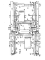
- the two side walls 1, 2 of a frame are connected to one another by cross members 3 and a shaft 4.
- the shaft 4 is rotatably supported in the side walls 1 and 2 and can be driven by a motor 5.
- the shaft 4 In its central region, the shaft 4 carries a contact roller 6, which is firmly connected to the shaft 4.
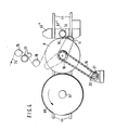
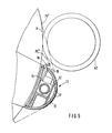
- the web lifter 11 consists of a profile tube 12 which is approximately semicircular in cross section for receiving a rodless cylinder 13.
- a piston carrier 14 is fixedly connected to the piston of this cylinder 13 and protrudes from a slot 15 of the profile tube 12 and has a knife blade 16 at its free end. Compressed air can be blown outwards through a plurality of slots 17 provided in the profile tube 12.
- the pivoting of the web lifter takes place via a sprocket 18 connected to a bearing ring 7, which is connected via a chain 19 to the sprocket 20 of a geared motor 21.
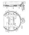
- both the upper and the lower half of each turning disc 43 are encompassed by a parallel guide chain 54 or 55, the upper parallel guide chain 54 being guided over deflection rollers 56 with the end shield 46 'and the lower one Parallel guide chain 55 guided over deflection rollers 57 with the end shield 46 "is firmly connected.
- a continuous shaft 58 is rotatably mounted below the turning discs 43, which has two sprockets 59. These two sprockets are connected to the two lower parallel guide chains 55.
- two chain pieces are placed on each turning disk 43 in this area, the ends 61 and 62 of which are firmly connected to the turning disks 43. From Fig. 8 it is clear that the transition chain pieces -59 and 60 are next to the parallel guide chains 54 and 55. In order to be able to bring both the transition chain pieces 59 and 60 and the parallel guide chains 54 and 55 into engagement with the chain wheel 59, this is designed as a wide double chain wheel.
- the turning disks 43 themselves are each equipped with an outer ring gear 63.
- a gear 64 meshes with the teeth of these sprockets, of which only one gear 64 is shown in FIG. 3.
- the two gear wheels 64 each belonging to two turning disks 43, are connected to one another by the turning disk drive shaft 65 and can be driven by the motor 66, which is fixedly connected to a frame side wall and the drive shaft of which is flanged to the turning disk drive shaft 65.
- winding sleeves 67 are seated on the winding shaft.
- the material web rolls 68 to be wound on these winding sleeves 67 are assigned pressure rollers 69 which are articulated via levers 70 to a rod 71 which is mounted in the frame side walls.
- the pressure rollers 69 are moved via pneumatic piston-cylinder units 72.
- FIG. 3 shows that each turning plate 43 has two locking bolts 73, 74 which can engage in corresponding openings in the end shields 46 in order to be able to lock the movement of the end shields 46 with respect to the turning plates 43. This happens whenever the two end shields 46 of two turning disks 43 are in the middle position, which is shown in the left half of FIG. 1.
- FIG. 1 shows a material web roll 68 'which has not yet been completely wound and on which the second narrow web part 75 "runs.
- the support roller 69 is pivoted onto the film roll.
- the end shields 46 are then 'Move to the right into the middle of the two turning disks 43 and lock there.
- the turning disks 43 are pivoted counterclockwise by the drive motor 66 until the newly inserted winding sleeve 67 "is in the winding position in which then the two linear guides 44 again run horizontally.
- the cutter bar 35 is pivoted counterclockwise by the piston-cylinder units 38 and 42, so that the material web 75 "can be cut through and a new winding can be formed.
- the position shown in FIG. 1 consequently, both on the left as well as on the right side of the device winding rolls are formed.
- the support rollers are first pivoted onto the rollers.
- the end shields 46 'shown on the right in FIG. 1 are then moved to the center of the turning disks 43 and locked there.
- the turning disks 43 are then rotated through the drive motor 66 by 180 ° until the end shields 46 "assume the position shown in FIG. 6 on the right side of the drawing.
- the device according to the invention can be switched back to an mode of operation in both the left and the right side of the device without interruption for example, a narrow web is wound up.
- the drive motor 21 of the web lifter 11 To this Purpose is first pivoted via the drive motor 21 of the web lifter 11 from its basic position shown with dash-dotted lines into the position shown with solid lines. This situation is shown in Fig. 5.
- the end shield 46 During the swiveling movement of the web lifter 11, the end shield 46 "is in a position remote from the contact roller 6. Only when the web lifter 11 has assumed the position shown in FIGS.
- the knife 16 of the web lifter is then actuated and only cuts through the web 75 ', but not the web 75'.
Landscapes
- Replacement Of Web Rolls (AREA)
- Winding Of Webs (AREA)
Priority Applications (1)
| Application Number | Priority Date | Filing Date | Title |
|---|---|---|---|
| AT87105212T ATE55357T1 (de) | 1986-04-28 | 1987-04-08 | Vorrichtung zum wickeln von mehreren durch laengsschneiden einer breiten materialbahn gebildeten schmalen materialbahnen zu vorratsrollen. |
Applications Claiming Priority (4)
| Application Number | Priority Date | Filing Date | Title |
|---|---|---|---|
| DE3614344 | 1986-04-28 | ||
| DE3614344 | 1986-04-28 | ||
| DE3636685 | 1986-10-28 | ||
| DE3636685A DE3636685C2 (de) | 1986-04-28 | 1986-10-28 | Vorrichtung zum Wickeln von mehreren durch Längsschneiden einer breiten Materialbahn gebildeten schmalen Materialbahnen zu Vorratsrollen |
Publications (3)
| Publication Number | Publication Date |
|---|---|
| EP0243748A2 true EP0243748A2 (fr) | 1987-11-04 |
| EP0243748A3 EP0243748A3 (en) | 1988-08-10 |
| EP0243748B1 EP0243748B1 (fr) | 1990-08-08 |
Family
ID=25843301
Family Applications (1)
| Application Number | Title | Priority Date | Filing Date |
|---|---|---|---|
| EP87105212A Expired - Lifetime EP0243748B1 (fr) | 1986-04-28 | 1987-04-08 | Dispositif pour enrouler plusieurs bandes minces obtenues par découpage longitudinal d'une bande large |
Country Status (5)
| Country | Link |
|---|---|
| US (1) | US4767075A (fr) |
| EP (1) | EP0243748B1 (fr) |
| JP (1) | JPH0798597B2 (fr) |
| CA (1) | CA1300112C (fr) |
| DE (1) | DE3645252C2 (fr) |
Cited By (5)
| Publication number | Priority date | Publication date | Assignee | Title |
|---|---|---|---|---|
| DE4232363A1 (de) * | 1992-09-26 | 1994-03-31 | Kloeckner Er We Pa Gmbh | Vorrichtung zum kontinuierlichen Wickeln von Materialbahnen |
| WO1997033821A1 (fr) * | 1996-03-13 | 1997-09-18 | Voith Sulzer Finishing Gmbh | Dispositif d'enroulement continu de bandes de papier coupees longitudinalement avec changement automatique des rouleaux a vitesse de la machine |
| EP0930261A2 (fr) * | 1998-01-20 | 1999-07-21 | Voith Sulzer Papiertechnik Patent GmbH | Méthode et dispositif pour enrouler des bandes refendues en rouleaux |
| DE19814906B4 (de) * | 1998-04-02 | 2004-03-04 | Lubinski, Waclaw, Dipl.-Ing. | Vorrichtung zum kontinuierlichen Wickeln von bahnförmigem Material |
| WO2012164115A1 (fr) * | 2011-06-01 | 2012-12-06 | Comexi Group Industries, Sau | Bobineuse de type revolver pour matériau en bande |
Families Citing this family (17)
| Publication number | Priority date | Publication date | Assignee | Title |
|---|---|---|---|---|
| DE4012979A1 (de) * | 1990-04-24 | 1991-11-07 | Jagenberg Ag | Verfahren und vorrichtung zum aufwickeln von materialbahnen, insbesondere papier- oder kartonbahnen |
| DE4441142C2 (de) * | 1994-11-18 | 1999-09-30 | Koenig & Bauer Ag | Zweirichtungsschwenkrahmen einer Papierrollenwechseleinrichtung |
| US6439502B1 (en) | 1995-02-28 | 2002-08-27 | Kimberly-Clark Worldwide, Inc. | Dispenser for coreless rolls of products |
| US5620148A (en) * | 1995-03-10 | 1997-04-15 | Kimberly-Clark Corporation | Methods of making indented coreless rolls |
| US5875985A (en) * | 1995-03-10 | 1999-03-02 | Kimberly-Clark Worldwide, Inc. | Indented coreless rolls and method of making the same |
| DE29515848U1 (de) * | 1995-10-06 | 1995-12-07 | Maschinenfabrik Goebel Gmbh, 64293 Darmstadt | Einrichtung zum Aufwickeln einer Bahn |
| DE19537677C1 (de) * | 1995-10-10 | 1997-03-20 | Reifenhaeuser Masch | Wickelmaschine, zum Aufwickeln einer fortlaufend zugeführten Werkstoffbahn, insbesondere zum Aufwickeln einer Folienbahn aus thermoplastischem Kunststoff |
| DE19538319C1 (de) * | 1995-10-14 | 1996-12-05 | Reifenhaeuser Masch | Wickelmaschine zum Aufwickeln einer fortlaufend zugeführten Werkstoffbahn |
| US6092758A (en) * | 1997-09-08 | 2000-07-25 | Kimberly-Clark Worldwide, Inc. | Adapter and dispenser for coreless rolls of products |
| US6092759A (en) * | 1997-09-08 | 2000-07-25 | Kimberly-Clark Worldwide, Inc. | System for dispensing coreless rolls of product |
| US6082664A (en) * | 1997-11-20 | 2000-07-04 | Kimberly-Clark Worldwide, Inc. | Coreless roll product and adapter |
| US6360985B1 (en) | 1998-05-29 | 2002-03-26 | Kimberly-Clark Worldwide, Inc. | Dispenser adapter for coreless rolls of products |
| USD428286S (en) * | 1998-05-29 | 2000-07-18 | Kimberly-Clark Worldwide | Dispenser adapter for coreless rolls of products |
| US6138939A (en) * | 1998-08-17 | 2000-10-31 | Kimberly Clark Worldwide, Inc. | Coreless adapter for dispensers of cored rolls of material |
| US6866213B2 (en) | 2001-12-28 | 2005-03-15 | Kimberely-Clark, Worldwide, Inc. | Rolled web products having a web wound in an oscillating fashion |
| US6641080B2 (en) | 2001-12-28 | 2003-11-04 | Kimberly-Clark Worldwide, Inc. | Method and apparatus for winding a web |
| JP5959259B2 (ja) * | 2012-03-26 | 2016-08-02 | 株式会社ジェイテクト | ウエブ巻取装置 |
Citations (5)
| Publication number | Priority date | Publication date | Assignee | Title |
|---|---|---|---|---|
| CH370682A (de) * | 1959-07-17 | 1963-07-15 | Kistler & Co | Verfahren zum Zerschneiden von kontinuierlich sich aufwickelnden Wattebahnen und Einrichtung zur Ausübung desselben |
| GB932151A (en) * | 1961-05-15 | 1963-07-24 | Du Pont | Method and apparatus for winding a continuous web |
| US3433429A (en) * | 1967-04-10 | 1969-03-18 | Midland Ross Corp | Film winding apparatus |
| GB1177431A (en) * | 1966-10-03 | 1970-01-14 | Paper Converting Machine Co | Multiple Web Winder |
| EP0093301A1 (fr) * | 1982-05-03 | 1983-11-09 | Klaus Günter Kühn | Dispositif pour changer le centre d'une bobine enroulée d'un matériel en bande |
Family Cites Families (9)
| Publication number | Priority date | Publication date | Assignee | Title |
|---|---|---|---|---|
| DE657852C (de) * | 1934-10-26 | 1938-03-15 | Eugen Schuermann Dr Ing | Einstellvorrichtung fuer Einzelobermesser an Umroll- und Laengsschneidemaschinen fuer Papier o. dgl. |
| DE1474243B1 (de) * | 1964-12-24 | 1969-12-18 | Goebel Gmbh Maschf | Maschine zum ununterbrochenen Aufwickeln einer laengsgeschnittenen Bahn |
| FR1445685A (fr) * | 1965-06-03 | 1966-07-15 | C I P S O | Perfectionnement aux dispositifs d'enroulage de bandes étroites obtenues par découpge d'une bande plus large |
| GB1153633A (en) * | 1965-10-13 | 1969-05-29 | Chambon Ltd | Improvements in Web Rewinding Machines |
| US3472462A (en) * | 1967-11-02 | 1969-10-14 | Dusenbery Co John | Turret winder for tape |
| DE2423021A1 (de) * | 1973-09-19 | 1975-04-30 | Polygraph Leipzig | Verfahren und vorrichtung zum kontinuierlichen wickeln von bahnfoermigem gut auf wickeltraeger |
| DE2705776A1 (de) * | 1977-02-11 | 1978-08-17 | Voith Gmbh J M | Vorrichtung zum kontinuierlichen wickeln von bahnen, insbesondere papierbahnen, auf wickelkerne |
| DE2724955C2 (de) * | 1977-06-02 | 1983-03-24 | Erwin Kampf Gmbh & Co Maschinenfabrik, 5276 Wiehl | Rollenwickelmaschine zur Bildung von Einzelwickeln |
| DE8233364U1 (de) * | 1982-11-27 | 1984-03-15 | J.M. Voith Gmbh, 7920 Heidenheim | Wickelmaschine zum aufwickeln einer laengsgeteilten bahn |
-
1986
- 1986-10-28 DE DE3645252A patent/DE3645252C2/de not_active Expired - Lifetime
-
1987
- 1987-04-08 EP EP87105212A patent/EP0243748B1/fr not_active Expired - Lifetime
- 1987-04-09 CA CA000534339A patent/CA1300112C/fr not_active Expired - Lifetime
- 1987-04-27 US US07/043,131 patent/US4767075A/en not_active Expired - Fee Related
- 1987-04-28 JP JP62106197A patent/JPH0798597B2/ja not_active Expired - Lifetime
Patent Citations (5)
| Publication number | Priority date | Publication date | Assignee | Title |
|---|---|---|---|---|
| CH370682A (de) * | 1959-07-17 | 1963-07-15 | Kistler & Co | Verfahren zum Zerschneiden von kontinuierlich sich aufwickelnden Wattebahnen und Einrichtung zur Ausübung desselben |
| GB932151A (en) * | 1961-05-15 | 1963-07-24 | Du Pont | Method and apparatus for winding a continuous web |
| GB1177431A (en) * | 1966-10-03 | 1970-01-14 | Paper Converting Machine Co | Multiple Web Winder |
| US3433429A (en) * | 1967-04-10 | 1969-03-18 | Midland Ross Corp | Film winding apparatus |
| EP0093301A1 (fr) * | 1982-05-03 | 1983-11-09 | Klaus Günter Kühn | Dispositif pour changer le centre d'une bobine enroulée d'un matériel en bande |
Cited By (11)
| Publication number | Priority date | Publication date | Assignee | Title |
|---|---|---|---|---|
| DE4232363A1 (de) * | 1992-09-26 | 1994-03-31 | Kloeckner Er We Pa Gmbh | Vorrichtung zum kontinuierlichen Wickeln von Materialbahnen |
| FR2696165A1 (fr) * | 1992-09-26 | 1994-04-01 | Kloeckner Erwepa Gmbh | Dispositif pour l'enroulement en continu de bandes de matière. |
| WO1997033821A1 (fr) * | 1996-03-13 | 1997-09-18 | Voith Sulzer Finishing Gmbh | Dispositif d'enroulement continu de bandes de papier coupees longitudinalement avec changement automatique des rouleaux a vitesse de la machine |
| US6406417B1 (en) | 1996-03-13 | 2002-06-18 | Voith Sulzer Papiertechnik Patent Gmbh | Device for continuously winding up longitudinally cut paper webs with rolls changed automatically at the machine speed |
| EP0930261A2 (fr) * | 1998-01-20 | 1999-07-21 | Voith Sulzer Papiertechnik Patent GmbH | Méthode et dispositif pour enrouler des bandes refendues en rouleaux |
| EP0930261A3 (fr) * | 1998-01-20 | 2000-03-15 | Voith Sulzer Papiertechnik Patent GmbH | Méthode et dispositif pour enrouler des bandes refendues en rouleaux |
| US6176449B1 (en) | 1998-01-20 | 2001-01-23 | Voith Sulzer Papiertechnik Patent Gmbh | Process and device for winding partial webs into partial web rolls |
| DE19814906B4 (de) * | 1998-04-02 | 2004-03-04 | Lubinski, Waclaw, Dipl.-Ing. | Vorrichtung zum kontinuierlichen Wickeln von bahnförmigem Material |
| WO2012164115A1 (fr) * | 2011-06-01 | 2012-12-06 | Comexi Group Industries, Sau | Bobineuse de type revolver pour matériau en bande |
| ES2393006A1 (es) * | 2011-06-01 | 2012-12-17 | Comexi Group Industries Sau | Bobinadora tipo revolver para material en banda. |
| US9284146B2 (en) | 2011-06-01 | 2016-03-15 | Comexi Group Industries, S.A. | Revolver-type winding machine for strip material |
Also Published As
| Publication number | Publication date |
|---|---|
| JPS6357460A (ja) | 1988-03-12 |
| JPH0798597B2 (ja) | 1995-10-25 |
| EP0243748B1 (fr) | 1990-08-08 |
| CA1300112C (fr) | 1992-05-05 |
| DE3645252C2 (de) | 1995-02-09 |
| US4767075A (en) | 1988-08-30 |
| EP0243748A3 (en) | 1988-08-10 |
Similar Documents
| Publication | Publication Date | Title |
|---|---|---|
| EP0243748B1 (fr) | Dispositif pour enrouler plusieurs bandes minces obtenues par découpage longitudinal d'une bande large | |
| DE2823326A1 (de) | Endstation einer maschine zur behandlung bandfoermigen materials, beispielsweise einer druckmaschine | |
| EP0289878B1 (fr) | Méthode et dispositif pour découper des étiquettes ayant des contours complexes | |
| DE3811159A1 (de) | Trenn- und aufwickelvorrichtung fuer bahnen und verfahren zum entfernen von aufwickelrollen | |
| DE2906598C2 (de) | Vorrichtung zur Bewerkstelligung eines fliegenden Wickelrollenwechsels | |
| DE3723827C2 (fr) | ||
| EP0427126B1 (fr) | Dispositif pour changer une bande | |
| DE3636685C2 (de) | Vorrichtung zum Wickeln von mehreren durch Längsschneiden einer breiten Materialbahn gebildeten schmalen Materialbahnen zu Vorratsrollen | |
| DE4414003A1 (de) | Verfahren und Vorrichtung zum Aufwickeln von Warenbahnen, insbesondere Kunststoffolien in einer Mehrfach-Wendewickelmaschine | |
| DE1237050B (de) | Kontinuierlich arbeitender Mehrtrommelhaspel fuer steifes Metallband | |
| EP2313335B1 (fr) | Dispositif et procédé pour enrouler et/ou dérouler des bandes de matériau | |
| EP0538566B1 (fr) | Machine pour enrouler des bandes de matière en bobines | |
| EP0216085A1 (fr) | Dispositif pour enrouler sans noyau des segments de bandes séparés de la bande le long de perforations transversales | |
| DE1574415A1 (de) | Mehrfachwickelvorrichtung | |
| DE2429917C3 (de) | Einrichtung zum automatischen Wechsel von Aufwickelkernen in Aufwickelmaschinen | |
| DE202014103124U1 (de) | Slitter zum Schneiden eines Cordbandes | |
| DE60200291T2 (de) | Umwickelmaschine mit Flanken zum Tragen von sich entlang einer geschlossenen Bahn bewegenden greifenden Zentrierdornen | |
| EP2803609B1 (fr) | Machine d'enroulement de matériaux en forme de bande | |
| DE2259734C2 (de) | Vorrichtung zum gegenseitigen Verbinden des Anfangs und des Endes von Materialbahnen, die nacheinander von Bahnwickelrollen ablaufen | |
| DE69403131T2 (de) | Automatischer Rollenwechsler für Verpackungsmaterialbahnen | |
| DE2243504C2 (de) | Vorrichtung zum fortlaufenden Aufwickeln einer Folienbahn auf Wickelhülsen | |
| EP2965896B1 (fr) | Découpeur d'une bande de corde | |
| DE2425454A1 (de) | Mehrwalzenwickler zum kontinuierlichen aufwickeln laufender warenbahnen | |
| EP3398740A1 (fr) | Dispositif de coupe permettant de couper une bande sans fin, en particulier une bande renforcée textile ou une bande en acier | |
| DE2755886A1 (de) | Vorrichtung zur kontinuierlichen zufuehrung von materialbahnen |
Legal Events
| Date | Code | Title | Description |
|---|---|---|---|
| PUAI | Public reference made under article 153(3) epc to a published international application that has entered the european phase |
Free format text: ORIGINAL CODE: 0009012 |
|
| AK | Designated contracting states |
Kind code of ref document: A2 Designated state(s): AT FR GB IT |
|
| PUAL | Search report despatched |
Free format text: ORIGINAL CODE: 0009013 |
|
| AK | Designated contracting states |
Kind code of ref document: A3 Designated state(s): AT FR GB IT |
|
| 17P | Request for examination filed |
Effective date: 19880826 |
|
| 17Q | First examination report despatched |
Effective date: 19881118 |
|
| GRAA | (expected) grant |
Free format text: ORIGINAL CODE: 0009210 |
|
| AK | Designated contracting states |
Kind code of ref document: B1 Designated state(s): AT FR GB IT |
|
| REF | Corresponds to: |
Ref document number: 55357 Country of ref document: AT Date of ref document: 19900815 Kind code of ref document: T |
|
| GBT | Gb: translation of ep patent filed (gb section 77(6)(a)/1977) | ||
| ET | Fr: translation filed | ||
| ITF | It: translation for a ep patent filed | ||
| ITTA | It: last paid annual fee | ||
| PLBE | No opposition filed within time limit |
Free format text: ORIGINAL CODE: 0009261 |
|
| STAA | Information on the status of an ep patent application or granted ep patent |
Free format text: STATUS: NO OPPOSITION FILED WITHIN TIME LIMIT |
|
| 26N | No opposition filed | ||
| REG | Reference to a national code |
Ref country code: GB Ref legal event code: IF02 |
|
| PGFP | Annual fee paid to national office [announced via postgrant information from national office to epo] |
Ref country code: GB Payment date: 20060410 Year of fee payment: 20 |
|
| PGFP | Annual fee paid to national office [announced via postgrant information from national office to epo] |
Ref country code: FR Payment date: 20060418 Year of fee payment: 20 |
|
| PGFP | Annual fee paid to national office [announced via postgrant information from national office to epo] |
Ref country code: AT Payment date: 20060424 Year of fee payment: 20 |
|
| PGFP | Annual fee paid to national office [announced via postgrant information from national office to epo] |
Ref country code: IT Payment date: 20060430 Year of fee payment: 20 |
|
| REG | Reference to a national code |
Ref country code: GB Ref legal event code: PE20 |
|
| PG25 | Lapsed in a contracting state [announced via postgrant information from national office to epo] |
Ref country code: GB Free format text: LAPSE BECAUSE OF EXPIRATION OF PROTECTION Effective date: 20070407 |