EP0243748A2 - Device for winding up several small webs after longitudinally slitting a large web - Google Patents
Device for winding up several small webs after longitudinally slitting a large web Download PDFInfo
- Publication number
- EP0243748A2 EP0243748A2 EP87105212A EP87105212A EP0243748A2 EP 0243748 A2 EP0243748 A2 EP 0243748A2 EP 87105212 A EP87105212 A EP 87105212A EP 87105212 A EP87105212 A EP 87105212A EP 0243748 A2 EP0243748 A2 EP 0243748A2
- Authority
- EP
- European Patent Office
- Prior art keywords
- winding
- web
- narrow
- webs
- guides
- Prior art date
- Legal status (The legal status is an assumption and is not a legal conclusion. Google has not performed a legal analysis and makes no representation as to the accuracy of the status listed.)
- Granted
Links
- 238000004804 winding Methods 0.000 title claims abstract description 123
- 239000000463 material Substances 0.000 claims abstract description 63
- 238000000034 method Methods 0.000 claims description 6
- 208000036829 Device dislocation Diseases 0.000 claims 1
- 230000007704 transition Effects 0.000 description 3
- 238000006073 displacement reaction Methods 0.000 description 2
- 210000002023 somite Anatomy 0.000 description 2
- 230000001360 synchronised effect Effects 0.000 description 2
- 239000000109 continuous material Substances 0.000 description 1
- 239000003292 glue Substances 0.000 description 1
- 239000002699 waste material Substances 0.000 description 1
- 230000037303 wrinkles Effects 0.000 description 1
Images


Classifications
-
- B—PERFORMING OPERATIONS; TRANSPORTING
- B65—CONVEYING; PACKING; STORING; HANDLING THIN OR FILAMENTARY MATERIAL
- B65H—HANDLING THIN OR FILAMENTARY MATERIAL, e.g. SHEETS, WEBS, CABLES
- B65H19/00—Changing the web roll
- B65H19/22—Changing the web roll in winding mechanisms or in connection with winding operations
- B65H19/2284—Simultaneous winding at several stations, e.g. slitter-rewinders
-
- B—PERFORMING OPERATIONS; TRANSPORTING
- B65—CONVEYING; PACKING; STORING; HANDLING THIN OR FILAMENTARY MATERIAL
- B65H—HANDLING THIN OR FILAMENTARY MATERIAL, e.g. SHEETS, WEBS, CABLES
- B65H2301/00—Handling processes for sheets or webs
- B65H2301/40—Type of handling process
- B65H2301/41—Winding, unwinding
- B65H2301/414—Winding
- B65H2301/4148—Winding slitting
- B65H2301/41486—Winding slitting winding on two or more winding shafts simultaneously
- B65H2301/414863—Winding slitting winding on two or more winding shafts simultaneously directly against central support roller
-
- B—PERFORMING OPERATIONS; TRANSPORTING
- B65—CONVEYING; PACKING; STORING; HANDLING THIN OR FILAMENTARY MATERIAL
- B65H—HANDLING THIN OR FILAMENTARY MATERIAL, e.g. SHEETS, WEBS, CABLES
- B65H2301/00—Handling processes for sheets or webs
- B65H2301/50—Auxiliary process performed during handling process
- B65H2301/51—Modifying a characteristic of handled material
- B65H2301/513—Modifying electric properties
- B65H2301/5133—Removing electrostatic charge
Definitions
- the invention relates to a device for winding a plurality of narrow material webs formed by longitudinally cutting a wide material web into supply rolls with guide rollers for the webs, with knives for longitudinally cutting the wide material web and with winding devices with winding cores for the narrower material webs.
- the object of the invention is to provide a device of this type which, with good winding quality of the supply rolls wound from the narrow material webs, permits a roll change with simple handling without interrupting the continuous web feed.
- this object is achieved in a device of the generic type in that two winding devices are provided on both sides of a central guide roller which diverges the narrow material webs in their running direction in a bogie rotatably mounted in the machine frame by turning drives provided with rotary drives, with axes of rotation parallel to the guide roller , which are guided in guides of the turning disks with winding axes movable on a diameter line parallel to themselves by drives that each of the two winding devices can be moved from an end region of the guides into the center of the bogie and that each is at the inner end at approximately horizontal
- a stationary guiding traversing winding device for changing rolls is assigned a separating knife with a pressure roller which is pivotably mounted in the machine frame and which sever the narrow material webs and the respective separate front end de r presses a narrow material web onto glued sleeves or the like forming the winding core.
- the device according to the invention permits continuous winding of the narrow material webs formed by cutting the wide material web lengthwise, no interruption of operation being necessary for the purpose of changing the reel.
- the support rollers are pivoted onto the rolls.
- the carriage is then moved into the center of the turning discs and the bogie is rotated by 180 °, so that the completely wound supply roll lies in the center of the bogie and a prepared winding core, for example a glued winding tube, for winding a new supply roll in the area of the central guide roller is pivoted.
- a prepared winding core for example a glued winding tube
- the separating knife is then actuated so that the web running onto the finished supply roll is cut and at the same time the beginning of the web formed by the separating cut is pressed onto the winding core.
- the new supply roll is now wound onto the new winding core, while the completely wound supply roll is moved from the center into the end region of the guides and removed and a new winding core is placed on the pin or the axis of the winding device in question.
- the almost completely wound supply roll according to its method in the center of the bogie can be blocked with this with the winding axis aligned with the axis of rotation of the bogie.
- the central guide roll forms a contact roll, against which the supply rolls that are formed are placed during winding. Air inclusions are reduced by the contact roller.
- the web to be wound can be fed tangentially with the desired tension.
- Rollers which are pivotably mounted on levers are expediently provided in the machine frame and can be adjusted to the supply rolls between the supply rolls moved into the center of the bogie and the contact roll. Before each movement of the supply rolls into the center of the bogie, i.e. at the beginning of each roll change, the rollers are pivoted onto the supply rolls and remain there until the supply rolls after the Roll changes can be removed from the machine. They are intended to prevent the web from running sideways during the process and to ensure that air pockets are avoided after the supply rolls have been removed from the contact roller.
- the two winding devices mounted in each bogie can be moved in their guides by means of spindles or pressure medium piston cylinder units.
- so-called rodless pneumatic cylinders are expediently used, which are provided with longitudinal slots in which pins connected directly to the piston are guided. These pins are connected to the parts of the winding devices to be moved.
- a further embodiment of the invention provides that opposite carriages which are movable in the guides and which carry the winding devices with their drives for synchronous guidance are connected to one another by the ends of chains running in guides concentric with the axis of rotation in the edge region of the turning disks are that mesh with sprockets that are attached to fixed shafts. Both sides are coupled via the chains, sprockets and the shaft, so that the parallelism of both carriages to the contact roller is ensured and tilting is avoided.
- the non-severed or severed narrow material webs then take the subsequent unseparated wide material web to the other winding device.
- the continuing narrow web or the continuing narrow webs are then separated in the manner described and a wide winding tube is kept ready as a new winding tube, onto which the remaining lengths of the narrow webs are initially wound as initial pieces. These pull the uncut wide web, which is then wound on only one side of the device.
- a supply roll change also takes place when winding a wide web in the manner described above.
- the web lifter is pivoted from its inactive position in the direction of travel of the web, so that the web lifter lifts the web from the central guide or contact roller.
- a prepared winding core for example a glued winding sleeve is pressed against the divided narrow web that is to be wound on the other winding point and pressed against the contact roller via the corresponding winding device, the narrow web can be wound on this, if previously by the separating knife the web lifter has severed this web, thereby creating a front end of the web to be wound up.
- the continuous, longitudinally separated web runs over the web lifter to the winding device on which the finished wound supply roll with the wide material web is located.
- a roll change is carried out in the manner described, the new winding core being formed by an appropriately prepared narrow winding core or narrow winding tube.
- the separating knife of the web lifter expediently cuts through the narrow web which only runs over a small wrap angle via the guide roller to the winding device.
- the curved sliding surface of the web lifter with perforations for Compressed air outlet is provided.
- the web lifter is provided with a chamber which is supplied with compressed air via corresponding lines and rotary unions.
- the separating knife can be displaceably guided in a longitudinal slot of the web lifter and can be moved by the piston of a rodless cylinder.
- the web lifter and / or the pivotably mounted knives are expediently pivotably supported via bearing rings on the shaft of the guide roller.
- the device according to the invention thus consists of a longitudinal cutting device with two winding stations which are designed as a turret winder.
- the winding can be done without an axle or with a winding shaft.
- the device enables a transition from the winding of a wide film to longitudinally cut films and vice versa in a fully automated manner.
- the two side walls 1, 2 of a frame are connected to one another by cross members 3 and a shaft 4.
- the shaft 4 is rotatably supported in the side walls 1 and 2 and can be driven by a motor 5.
- the shaft 4 In its central region, the shaft 4 carries a contact roller 6, which is firmly connected to the shaft 4.
- the web lifter 11 consists of a profile tube 12 which is approximately semicircular in cross section for receiving a rodless cylinder 13.
- a piston carrier 14 is fixedly connected to the piston of this cylinder 13 and protrudes from a slot 15 of the profile tube 12 and has a knife blade 16 at its free end. Compressed air can be blown outwards through a plurality of slots 17 provided in the profile tube 12.
- the pivoting of the web lifter takes place via a sprocket 18 connected to a bearing ring 7, which is connected via a chain 19 to the sprocket 20 of a geared motor 21.
- both the upper and the lower half of each turning disc 43 are encompassed by a parallel guide chain 54 or 55, the upper parallel guide chain 54 being guided over deflection rollers 56 with the end shield 46 'and the lower one Parallel guide chain 55 guided over deflection rollers 57 with the end shield 46 "is firmly connected.
- a continuous shaft 58 is rotatably mounted below the turning discs 43, which has two sprockets 59. These two sprockets are connected to the two lower parallel guide chains 55.
- two chain pieces are placed on each turning disk 43 in this area, the ends 61 and 62 of which are firmly connected to the turning disks 43. From Fig. 8 it is clear that the transition chain pieces -59 and 60 are next to the parallel guide chains 54 and 55. In order to be able to bring both the transition chain pieces 59 and 60 and the parallel guide chains 54 and 55 into engagement with the chain wheel 59, this is designed as a wide double chain wheel.
- the turning disks 43 themselves are each equipped with an outer ring gear 63.
- a gear 64 meshes with the teeth of these sprockets, of which only one gear 64 is shown in FIG. 3.
- the two gear wheels 64 each belonging to two turning disks 43, are connected to one another by the turning disk drive shaft 65 and can be driven by the motor 66, which is fixedly connected to a frame side wall and the drive shaft of which is flanged to the turning disk drive shaft 65.
- winding sleeves 67 are seated on the winding shaft.
- the material web rolls 68 to be wound on these winding sleeves 67 are assigned pressure rollers 69 which are articulated via levers 70 to a rod 71 which is mounted in the frame side walls.
- the pressure rollers 69 are moved via pneumatic piston-cylinder units 72.
- FIG. 3 shows that each turning plate 43 has two locking bolts 73, 74 which can engage in corresponding openings in the end shields 46 in order to be able to lock the movement of the end shields 46 with respect to the turning plates 43. This happens whenever the two end shields 46 of two turning disks 43 are in the middle position, which is shown in the left half of FIG. 1.
- FIG. 1 shows a material web roll 68 'which has not yet been completely wound and on which the second narrow web part 75 "runs.
- the support roller 69 is pivoted onto the film roll.
- the end shields 46 are then 'Move to the right into the middle of the two turning disks 43 and lock there.
- the turning disks 43 are pivoted counterclockwise by the drive motor 66 until the newly inserted winding sleeve 67 "is in the winding position in which then the two linear guides 44 again run horizontally.
- the cutter bar 35 is pivoted counterclockwise by the piston-cylinder units 38 and 42, so that the material web 75 "can be cut through and a new winding can be formed.
- the position shown in FIG. 1 consequently, both on the left as well as on the right side of the device winding rolls are formed.
- the support rollers are first pivoted onto the rollers.
- the end shields 46 'shown on the right in FIG. 1 are then moved to the center of the turning disks 43 and locked there.
- the turning disks 43 are then rotated through the drive motor 66 by 180 ° until the end shields 46 "assume the position shown in FIG. 6 on the right side of the drawing.
- the device according to the invention can be switched back to an mode of operation in both the left and the right side of the device without interruption for example, a narrow web is wound up.
- the drive motor 21 of the web lifter 11 To this Purpose is first pivoted via the drive motor 21 of the web lifter 11 from its basic position shown with dash-dotted lines into the position shown with solid lines. This situation is shown in Fig. 5.
- the end shield 46 During the swiveling movement of the web lifter 11, the end shield 46 "is in a position remote from the contact roller 6. Only when the web lifter 11 has assumed the position shown in FIGS.
- the knife 16 of the web lifter is then actuated and only cuts through the web 75 ', but not the web 75'.
Landscapes
- Replacement Of Web Rolls (AREA)
- Winding Of Webs (AREA)
Abstract
Eine Vorrichtung zum Wickeln von mehreren durch Längsschneiden einer breiten Materialbahn gebildeten schmalen Materialbahnen zu Vorratsrollen weist Leitwalzen für die Bahnen, Messer zum Längsschneiden der breiten Materialbahn und Wickeleinrichtungen mit Wickelkernen für die schmalen Materialbahnen auf. Um einen Rollenwechsel ohne Unterbrechung der kontinuierlichen Bahnzuführung bei einfacher Handhabung zu ermöglichen, sind beidseits einer zentralen, die schmalen Materialbahnen in ihrer Laufrichtung auseinander führenden Führungswalze (6) in je einem durch mit Drehantrieben versehenen Wendescheiben (43) drehbar im Maschinengestell (1,2,3) gelagerten Drehgestell mitzu der Führungswalze (6) paralleler Drehachse je zwei Wickeleinrichtungen (46,46') vorgesehen, die in Führungen (44) der Wendescheiben (43) mit auf einer Durchmesserlinie verfahrbaren Wickelachsen (51) parallel zu sich selbst durch Antriebe verschiebbar geführ sind. Jede der jeweils zwei Wickeleinrichtungen (46,46') ist von einem Endbereich der Führungen (44) in den Bereich des Zentrums des Drehgestells verfahrbar. Jeder der jeweils an das innere Ende bei etwa horizontal stehenden Führungen (44) verfahrbaren Wickeleinrichtungen ist zum Rollenwechsel ein im Maschinengestell schwenkbar gelagertes Trennmesser mit Andrückrolle zugeordnet, die die schmalen Materialbahnen durchtrennen und die getrennten vorderen Enden der Materialbahnen auf beleimte, Wickelkerne bildende Hülsen andrücken (Figur 1).
Description
Die Erfindung betrifft eine Vorrichtung zum Wickeln von mehreren-durch Längsschneiden einer breiten Materialbahn gebildeten schmalen Materialbahnen zu Vorratsrollen mit Leitwalzen für die Bahnen, mit Messern zum Längsschneiden der breiten Materialbahn und mit Wickeleinrichtungen mit Wickelkernen für die schmaleren Materialbahnen.The invention relates to a device for winding a plurality of narrow material webs formed by longitudinally cutting a wide material web into supply rolls with guide rollers for the webs, with knives for longitudinally cutting the wide material web and with winding devices with winding cores for the narrower material webs.
Vorrichtungen dieser Art sind beispielsweise aus der DE-AS 14 74 243 und der DE-GMS 82 33 364 bekannt.Devices of this type are known for example from DE-AS 14 74 243 and DE-GMS 82 33 364.
Aufgabe der Erfindung ist es, eine Vorrichtung dieser Art zu schaffen, die bei guter Wickelqualität der aus den schmalen Materialbahnen gewickelten Vorratsrollen ohne Unterbrechung der kontinuierlichen Bahnzuführung einen Rollenwechsel bei einfacher Handhabung gestattet.The object of the invention is to provide a device of this type which, with good winding quality of the supply rolls wound from the narrow material webs, permits a roll change with simple handling without interrupting the continuous web feed.
Erfindungsgemäß wird diese Aufgabe bei einer Vorrichtung der gattungsgemäßen Art dadurch gelöst, daß beidseits einer zentralen, die schmalen Materialbahnen in ihrer Laufrichtung auseinanderführenden Führungswalze in je einem durch mit Drehantrieben versehenen Wendescheiben drehbar im Maschinengestell gelagerten Drehgestell mit zu der Führungswalze parallelen Drehachsen je zwei Wickeleinrichtungen vorgesehen sind, die in Führungen der Wendescheiben mit auf einer Durchmesserlinie verfahrbaren Wickelachsen parallel zu sich selbst durch Antriebe verschiebbar geführt sind, daß jede der jeweils zwei Wickeleinrichtungen von einem Endbereich der Führungen in das Zentrum des Drehgestells verfahrbar ist und daß jeder an das innere Ende bei etwa horizontal stehender Führung verfahrenen Wickeleinrichtung zum Rollenwechsel ein im Maschinengestell schwenkbar gelagertes "Trennmesser mit Andrückwalze zugeordnet ist, die die schmalen Materialbahnen durchtrennen und das jeweils getrennte vordere Ende der schmalen Materialbahn auf beleimte, den Wickelkern bildende Hülsen o. dgl. andrückt.According to the invention, this object is achieved in a device of the generic type in that two winding devices are provided on both sides of a central guide roller which diverges the narrow material webs in their running direction in a bogie rotatably mounted in the machine frame by turning drives provided with rotary drives, with axes of rotation parallel to the guide roller , which are guided in guides of the turning disks with winding axes movable on a diameter line parallel to themselves by drives that each of the two winding devices can be moved from an end region of the guides into the center of the bogie and that each is at the inner end at approximately horizontal A stationary guiding traversing winding device for changing rolls is assigned a separating knife with a pressure roller which is pivotably mounted in the machine frame and which sever the narrow material webs and the respective separate front end de r presses a narrow material web onto glued sleeves or the like forming the winding core.
Die erfindungsgemäße Vorrichtung gestattet ein kontinuierliches Wickeln der durch Längsschneiden der breiten Materialbahn gebildeten schmalen Materialbahnen, wobei zum Zwecke des Rollenwechsels keine Betriebsunterbrechung erforderlich ist. Hat eine aus einer schmalen Materialbahn gewickelte Vorratsrolle den gewünschten Durchmesser erreicht, werden die Auflagewalzen an die Rollen geschwenkt. Anschließend wird der Schlitten in das Zentrum der Wendescheiben verfahren und das Drehgestell um 180° gedreht, so daß die fertig gewickelte Vorratsrolle im Zentrum des Drehgestells liegt und ein vorbereiteter Wickelkern, beispielsweise eine beleimte Wickelhülse, zum Wickeln einer neuen Vorratsrolle in den Bereich der zentralen Führungswalze geschwenkt wird. Sobald durch Drehung des Drehgestells die fertig gewickelte Vorratsrolle um sich selbst und der vorbereitete Wickelkern nach innen geschwenkt worden sind, legt sich die Andrückwalze an die Wickelhülse. Anschließend wird das Trennmesser betätigt, so daß die auf die fertige Vorratsrolle laufende Bahn durchtrennt und gleichzeitig der durch den Trennschnitt gebildete Bahnanfang auf den Wickelkern angedrückt wird. Auf den neuen Wickelkern wird nun die neue Vorratsrolle aufgewickelt, während die fertig gewickelte Vorratsrolle aus dem Zentrum in den Endbereich der Führungen gefahren und entnommen wird und auf die Zapfen oder die Achse der betreffenden Wickelvorrichtung ein neuer Wickelkern aufgesetzt wird.The device according to the invention permits continuous winding of the narrow material webs formed by cutting the wide material web lengthwise, no interruption of operation being necessary for the purpose of changing the reel. When a supply roll wound from a narrow material web has reached the desired diameter, the support rollers are pivoted onto the rolls. The carriage is then moved into the center of the turning discs and the bogie is rotated by 180 °, so that the completely wound supply roll lies in the center of the bogie and a prepared winding core, for example a glued winding tube, for winding a new supply roll in the area of the central guide roller is pivoted. As soon as by rotating the bogie the finished wound supply roll around itself and the prepared winding core have been pivoted inwards, the pressure roller lies on the winding tube. The separating knife is then actuated so that the web running onto the finished supply roll is cut and at the same time the beginning of the web formed by the separating cut is pressed onto the winding core. The new supply roll is now wound onto the new winding core, while the completely wound supply roll is moved from the center into the end region of the guides and removed and a new winding core is placed on the pin or the axis of the winding device in question.
Um zu vermeiden, daß durch das Verschwenken des Drehgestells zur Vorbereitung des Rollenwechsels in der Bahn infolge von Änderung der Lauflänge der Bahn unerwünschte Zugspannungsschwankungen auftreten,ist in weiterer Ausgestaltung der Erfindung vorgesehen, daß die nahezu fertig gewickelte Vorratsrolle nach ihrem Verfahren in das Zentrum des Drehgestells mit diesem mit mit der Drehachse des Drehgestells fluchtender Wickelachse blockierbar ist.In order to avoid that undesirable tension fluctuations occur due to the pivoting of the bogie in preparation for the roll change in the web due to a change in the running length of the web, it is provided in a further embodiment of the invention that the almost completely wound supply roll according to its method in the center of the bogie can be blocked with this with the winding axis aligned with the axis of rotation of the bogie.
Um eine gute und feste Wicklung der Vorratsrollen zu erreichen, ist in weiterer Ausgestaltung der Erfindung vorgesehen, daß die zentrale Führungswalze eine Kontaktwalze bildet, an die die sich bildenden Vorratsrollen während des Wickelns angestellt sind. Durch die Kontaktwalze werden Lufteinschlüsse verringert. Außerdem kann die zu wickelnde Bahn tangential mit der gewünschten Zugspannung zugeführt werden.In order to achieve a good and firm winding of the supply rolls, it is provided in a further embodiment of the invention that the central guide roll forms a contact roll, against which the supply rolls that are formed are placed during winding. Air inclusions are reduced by the contact roller. In addition, the web to be wound can be fed tangentially with the desired tension.
Zweckmäßigerweise sind im Maschinengestell über Hebel schwenkbar gelagerte Walzen vorgesehen, die an die Vorratsrollen zwischen den in die Mitte des Drehgestells verfahrenen Vorratsrollen und der Kontaktwalze anstellbar sind. Die Walzen werden vor jedem Verfahren der Vorratsrollen in das Zentrum des Drehgestells, also zu Beginn eines jeden Rollenwechsels, an die Vorratsrollen angeschwenkt und bleiben dort, bis die Vorratsrollen nach dem Rollenwechsel aus der Maschine entnommen werden. Sie sollen ein seitliches Verlaufen der Bahn während des Verfahrens verhindern und dafür sorgen, daß Lufteinschlüsse nach dem Entfernen der Vorratsrollen von der Kontaktwalze vermieden werden.Rollers which are pivotably mounted on levers are expediently provided in the machine frame and can be adjusted to the supply rolls between the supply rolls moved into the center of the bogie and the contact roll. Before each movement of the supply rolls into the center of the bogie, i.e. at the beginning of each roll change, the rollers are pivoted onto the supply rolls and remain there until the supply rolls after the Roll changes can be removed from the machine. They are intended to prevent the web from running sideways during the process and to ensure that air pockets are avoided after the supply rolls have been removed from the contact roller.
Die beiden in jedem Drehgestell gelagerten Wickeleinrichtungen können durch Spindeln oder Druckmittelkolbenzylindereinheiten in ihren Führungen verfahrbar sein. Aus Gründen der Platzersparnis werden zweckmäßigerweise sogenannte kolbenstangenlose Pneumatikzylinder verwendet, die mit Längsschlitzen versehen sind, in denen unmittelbar mit dem Kolben verbundene Stifte geführt sind. Diese Stifte sind mit den zu verfahrenden Teilen der Wickelvorrichtungen verbunden.The two winding devices mounted in each bogie can be moved in their guides by means of spindles or pressure medium piston cylinder units. To save space, so-called rodless pneumatic cylinders are expediently used, which are provided with longitudinal slots in which pins connected directly to the piston are guided. These pins are connected to the parts of the winding devices to be moved.
Da Pneumatikzylinder keinen sicheren Gleichlauf gewährleisten, ist in weiterer Ausgestaltung der Erfindung vorgesehen, daß gegenüberliegende, in den Führungen verfahrbare, die Wickeleinrichtungen mit ihren Antrieben tragende Schlitten zur Gleichlaufführung mit den Enden von über im Randbereich der Wendescheiben in zur Drehachse konzentrischen Führungen laufende Ketten miteinander verbunden sind, die mit Kettenrädern kämmen, die auf gestellfesten Wellen befestigt sind. Uber die Ketten, Kettenräder und die Welle sind beide Seiten gekoppelt, so daß die Parallelität beider Schlitten zur Kontaktwalze gewährleistet und ein Verkanten vermieden ist.Since pneumatic cylinders do not ensure reliable synchronization, a further embodiment of the invention provides that opposite carriages which are movable in the guides and which carry the winding devices with their drives for synchronous guidance are connected to one another by the ends of chains running in guides concentric with the axis of rotation in the edge region of the turning disks are that mesh with sprockets that are attached to fixed shafts. Both sides are coupled via the chains, sprockets and the shaft, so that the parallelism of both carriages to the contact roller is ensured and tilting is avoided.
Selbstverständlich ist es möglich, die breite Materialbahn in mehr als zwei streifenförmige Materialbahnen zu unterteilen und diese abwechselnd über die Kontaktwalze nach links und rechts zu führen und auf gleichachsig angeordneten Wickelkernen, vorzugsweise sogenannten Friktionswickelwellen, der Wickelvorrichtungen in der beschriebenen Weise aufzuwickeln.Of course, it is possible to subdivide the wide material web into more than two strip-shaped material webs and to guide them alternately to the left and right over the contact roller and to wind up the winding devices in the manner described on coaxially arranged winding cores, preferably so-called friction winding shafts.
Bei Wickelvorrichtungen der eingangs angegebenen Art besteht nun auch das Bedürfnis, die breite Materialbahn ungeschnitten zu einer breiten Vorratsrolle aufzuwickeln, ohne hierzu eine besondere Wickeleinrichtung zu benötigen. Dabei ist es besonders wünschenswert, ohne Unterbrechung der Zuführung der breiten Materialbahn die Vorrichtung von der Wicklung von zwei oder mehrerer durch Längsschneiden gebildeter streifenförmiger Materialbahnen auf die Wicklung der breiten unbeschnittenen Materialbahn umstellen zu können. Um den Anwendungsbereich der Vorrichtung in dieser Weise erweitern zu können, ist nach einer erfinderischen Ausgestaltung vorgesehen, daß die die breite Materialbahn längsschneidenden Messer von dieser abhebbar sind und daß auf einer Seite der Führungswalze im Maschinengestell an Schwenkhebeln ein Trennmesser schwenkbar gelagert ist, das eine der zu einer Vorratsrolle laufenden schmalen Bahn oder die zu einer Seite laufenden schmalen Bahnen durchtrennt. Die nicht durchtrennte oder durchtrennten schmalen Materialbahnen nehmen sodann die nachfolgende ungetrennte breite Materialbahn zu der anderen Wickelvorrichtung mit. Die weiterlaufende schmale Bahn oder die weiterlaufenden schmalen Bahnen werden sodann in der beschriebenen Weise getrennt und als neue Wickelhülse wird eine breite Wickelhülse bereitgehalten, auf die zunächst als Anfangsstücke die verbleibenden Restlängen der schmalen Bahnen aufgewickelt werden. Diese ziehen die ungeschnittene breite Bahn nach, die anschliessend nur auf einer Seite der Vorrichtung gewickelt wird. Ein Vorratsrollenwechsel vollzieht sich auch beim Wickeln einer breiten Bahn in der zuvor beschriebenen Weise.In the case of winding devices of the type specified at the beginning there is now also the need to wind up the wide web of material uncut into a wide supply roll without the need for a special winding device. It is particularly desirable to be able to switch the device from the winding of two or more strip-shaped material webs formed by slitting to the winding of the wide untrimmed material web without interrupting the feeding of the wide material web. In order to be able to expand the scope of the device in this way, it is provided according to an inventive embodiment that the wide material web slitting knives can be lifted from this and that on one side of the guide roller in the machine frame on pivoting levers, a cutting knife is pivotally mounted, one of the severed to a supply roll running narrow web or the narrow webs running to one side. The non-severed or severed narrow material webs then take the subsequent unseparated wide material web to the other winding device. The continuing narrow web or the continuing narrow webs are then separated in the manner described and a wide winding tube is kept ready as a new winding tube, onto which the remaining lengths of the narrow webs are initially wound as initial pieces. These pull the uncut wide web, which is then wound on only one side of the device. A supply roll change also takes place when winding a wide web in the manner described above.
Umgekehrt ist es nun auch zur Erweiterung des Anwendungsbereiches der Vorrichtung wünschenswert, den Wickelbetrieb von der Wicklung einer breiten Folie auf nur einer Seite der Vorrichtung wieder auf das Wickeln zweier oder mehrerer durch Längsschneiden gebildeter schmaler Materialbahnen auf beiden Seiten der zentralen Führungswalze umstellen zu können. Nach einer weiteren erfinderischen Weiterbildung ist daher vorgesehen, daß im Maschinengestell gleichachsig mit der Führungswalze an Schwenkhebeln ein sich über deren Länge erstreckender Bahnabheber schwenkbar gelagert ist, der mit einem nur eine oder die einen der schmalen Bahnen durchtrennenden Trennmesser versehen ist. Um die Umstellung des Betriebes von der Wicklung einer breiten Materialbahn auf die Wicklung zweier oder mehrerer längsgeteilter schmaler Materialbahnen vorzunehmen, werden zunächst die die Bahn in mehrere schmale Bahnen trennenden Messer eingeschwenkt. Gleichzeitig oder anschließend wird der Bahnabheber aus seiner inaktiven Stellung in Laufrichtung der Bahn verschwenkt, so daß der Bahnabheber die Bahn von der zentralen Führungs- oder Kontaktwalze abhebt. Wird nun ein vorbereiteter Wickelkern, beispielsweise eine beleimte Wickelhülse über die entsprechende Wickeleinrichtung gegen die geteilte schmale Bahn, die auf der anderen Wikkelstelle zu wickeln ist, unter Andruck an die Kontaktwalze herangefahren, kann auf dieser die schmale Bahn gewickelt werden, wenn zuvor durch das Trennmesser des Bahnabhebers diese Bahn durchtrennt und dadurch ein vorderes aufzuwickelndes Ende der Bahn geschaffen worden ist. Die weiterlaufende, längsgetrennte Bahn läuft über den Bahnabheber zu der Wickelvorrichtung, auf der sich die fertig gewickelte Vorratsrolle mit der breiten Materialbahn befindet. Sobald die schmale Materialbahn auf die Wickelrolle aufläuft, wird in der beschriebenen Weise ein Rollenwechsel vorgenommen, wobei der neue Wickelkern durch einen entsprechend vorbereiteten schmalen Wickelkern bzw. schmale Wickelhülse gebildet ist.Conversely, in order to expand the area of application of the device, it is now desirable to be able to switch the winding operation from the winding of a wide film on only one side of the device back to the winding of two or more narrow material webs formed by slitting on both sides of the central guide roller. After another An inventive development is therefore provided that in the machine frame coaxially with the guide roller on pivoting levers, a web lifter extending over its length is pivotally mounted, which is provided with a separating knife which cuts only one or one of the narrow webs. In order to convert the operation from the winding of a wide material web to the winding of two or more longitudinally divided narrow material webs, the knives separating the web are first pivoted into several narrow webs. Simultaneously or subsequently, the web lifter is pivoted from its inactive position in the direction of travel of the web, so that the web lifter lifts the web from the central guide or contact roller. If a prepared winding core, for example a glued winding sleeve is pressed against the divided narrow web that is to be wound on the other winding point and pressed against the contact roller via the corresponding winding device, the narrow web can be wound on this, if previously by the separating knife the web lifter has severed this web, thereby creating a front end of the web to be wound up. The continuous, longitudinally separated web runs over the web lifter to the winding device on which the finished wound supply roll with the wide material web is located. As soon as the narrow material web runs onto the winding roll, a roll change is carried out in the manner described, the new winding core being formed by an appropriately prepared narrow winding core or narrow winding tube.
Zweckmäß-igerweie durchtrennt das Trennmesser des Bahnabhebers die nur über einen kleineren Umschlingungswinkel über die Führungswalze zu der Wickeleinrichtung laufende schmale Bahn.The separating knife of the web lifter expediently cuts through the narrow web which only runs over a small wrap angle via the guide roller to the winding device.
In weiterer Ausgestaltung der Erfindung ist vorgesehen, daß die gewölbte Gleitfläche des Bahnabhebers mit Perforationen zum Austritt von Druckluft versehen ist. Bei dieser Ausgestaltung ist der Bahnabheber mit einer Kammer versehen, der über entsprechende Leitungen und Drehdurchführungen Druckluft zugeführt wird.In a further embodiment of the invention it is provided that the curved sliding surface of the web lifter with perforations for Compressed air outlet is provided. In this embodiment, the web lifter is provided with a chamber which is supplied with compressed air via corresponding lines and rotary unions.
Das Trennmesser kann in einem Längsschlitz des Bahnabhebers querverschieblich geführt und durch den Kolben eines kolbenstangenlosen Zylinders bewegbar sein.The separating knife can be displaceably guided in a longitudinal slot of the web lifter and can be moved by the piston of a rodless cylinder.
Zweckmäßigerweise sind der Bahnabheber und/oder die schwenkbar gelagerten Messer über Lagerringe auf der Welle der Führungswalze schwenkbar gelagert.The web lifter and / or the pivotably mounted knives are expediently pivotably supported via bearing rings on the shaft of the guide roller.
Insgesamt besteht also die erfindungsgemäße Vorrichtung aus einer Längsschneidvorrichtung mit zwei Wickelstellen, die als Wendewickler ausgebildet sind.Overall, the device according to the invention thus consists of a longitudinal cutting device with two winding stations which are designed as a turret winder.
Zusätzlich besteht wahlweise die Möglichkeit, die ungetrennte breite Folie auf einer Wickelstelle zu wickeln. Das Wickeln kann - dabei achslos oder mit Wickelwelle erfolgen.In addition, there is the option of wrapping the undivided wide film on one winding point. The winding can be done without an axle or with a winding shaft.
Die Vorrichtung ermöglicht vollautomatisch bei entsprechender Steuerung einen Übergang von der Wicklung einer breiten Folie auf längsgeschnittene Folien und umgekehrt.With appropriate control, the device enables a transition from the winding of a wide film to longitudinally cut films and vice versa in a fully automated manner.
Bei der erfindungsgemäßen Vorrichtung gehen bei einer Umschaltung der Betriebsweise nur kurze Bahnlängen als Abfall verloren. Die zu bildenden Vorratsrollen legen sich gegen die zentrale Führungs- oder Kontaktwalze. Hierdurch werden Lufteinschlüsse und Falten verhindert.In the device according to the invention, only a short web length is lost as waste when the operating mode is switched. The supply rolls to be formed lie against the central guide or contact roller. This prevents air pockets and wrinkles.
Während des gesamten Rollenwechselvorgangs finden lediglich geringe Längenänderungen und damit geringe Bahnzugspannungs- änderungen statt, wodurch auch während des Rollenwechsels eine hohe Wickelqualität gewährleistet ist. Dies ist auf folgende Maßnahmen zurückzuführen:
- - Die Vorratsrollen werden in das Zentrum der Wendescheibe verfahren, bevor die Wendescheiben verschwenkt werden.
- - Die Auflagewalze wird an die Vorratsrolle (n) angelegt, bevor die Rolle (n) verfahren und bevor - die Wendescheibe durchgeschwenkt wird.
- - Der Ort, an dem die Andrückwalze an der Vorratsrolle (den Vorratsrollen) anliegt, ist nahezu der Auflaufort der zulaufenden Bahn auf die Vorratsrolle (n). Somit wird gewährleistet, daß die zulaufende Bahn beim Verfahren der Rolle in das Zentrum der Wendescheibe in ihrer Länge nur unwesentlich verändert wird. Dadurch können auch keine wesentlichen Zugspannungsänderungen auftreten, die zum Verlaufen der Folienbahn führen können.
- - Die Rollenwechseleinrichtungen sind so gestaltet, daß die Andrückrollen der Rollenwechseleinrichtung, die die Bahn berühren, nur eine geringe Umschlingung der zulaufenden Bahn hervorrufen und somit keine wesentlichen Längenänderungen der zulaufenden Bahn bzw. Zugspannungsänderungen auftreten.
- - The supply rolls are moved into the center of the turning disc before the turning discs are pivoted.
- - The support roller is placed on the supply roll (s) before the roll (s) move and before - the turning disc is swung through.
- - The place where the pressure roller lies against the supply roll (the supply rolls) is almost the point of contact of the incoming web onto the supply roll (s). This ensures that the length of the incoming web is only slightly changed when moving the roll into the center of the turning disc. As a result, no significant changes in tensile stress can occur, which can lead to the film web running.
- - The roll changing devices are designed so that the pressure rollers of the roll changing device, which touch the web, cause only a slight wrap of the incoming web and thus no significant changes in length of the incoming web or changes in tension occur.
Ein Ausführungsbeispiel der Erfindung wird nachstehend anhand der Zeichnung näher erläutert. In dieser zeigt
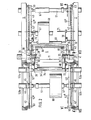
- Fig. 1 eine Seitenansicht der Wickelvorrichtung in schematischer Darstellung,
- Fig. 2 eine Draufsicht auf die Vorrichtung gemäß der Linie II-II in Fig. 1,
- Fig. 3 einen Schnitt durch die Vorrichtung gemäß der Linie III-III in Fig. 1
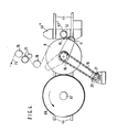
- Fig. 4 den mittleren Teil der in Fig. 1 dargestellten Wickelvorrichtung während des Umstellens der Betriebsweise von dem Wickeln einer Breitfolie auf einer Wickelstelle auf das Wickeln längsgeteilter schmaler Materialbahnen auf zwei Wickelstellen,
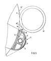
- Fig. 5 den in seine Betriebsstellung.geschwenkten Bahnabheber nach Fig. 4 in vergrößerter Darstellung
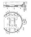
- Fig. 6 einen Schnitt durch die Vorrichtung gemäß der Linie VI-VI in Fig. 2 während des Umstellens des Wickelns von mehreren schmalen Materialbahnen auf eine breite Materialbahn,
- Fig. 7 einen Schnitt durch die Vorrichtung längs der Linie VII-VII in Fig. 2 und
- Fig. 8 eine Seitenanansicht der mit Gleichlaufführungen versehenen Wendescheibe nach Fig. 7.
- 1 is a side view of the winding device in a schematic representation,
- 2 is a plan view of the device along the line II-II in Fig. 1,
- 3 shows a section through the device according to line III-III in FIG. 1
- 4 shows the middle part of the winding device shown in FIG. 1 during the changeover of the mode of operation from the winding of a wide film on one winding point to the winding of narrowly divided material webs on two winding points,
- 5 shows the web lifter pivoted into its operating position according to FIG. 4 in an enlarged view
- 6 shows a section through the device according to line VI-VI in FIG. 2 during the changeover of the winding from several narrow material webs to a wide material web,
- Fig. 7 shows a section through the device along the line VII-VII in Fig. 2 and
- 8 is a side view of the reversing disk provided with synchronous guides according to FIG. 7.
Die beiden Seitenwände 1,2 eines Rahmens sind durch Traversen 3 und eine Welle 4 miteinander verbunden. Die Welle 4 ist drehbar in den Seitenwänden 1 und 2 gelagert und kann über einen Motor 5 angetrieben werden. In ihrem mittleren Bereich trägt die Welle 4 eine Konktakwalze 6, die mit der Welle 4 fest verbunden ist.The two
Nahe der Kontaktwalze 6 befinden sich frei drehbar auf der Welle 4 zwei Lagerringe 7 und 8, die je einen Hebelarm 9 und 10 aufweisen. Die den Lagerringen 7 und 8 abgewandten Enden der Hebelarme 9 und 10 tragen einen sich über die gesamte Breite der Kontaktwalze 6 erstreckenden Bahnabheber 11, der in Fig. 5 deutlicher dargestellt ist. Wie aus Fig. 5 ersichtlich ist, besteht der Bahnabheber 11 aus einem im Querschnitt etwa halbkreisförmigen Profilrohr 12 zur Aufnahme eines kolbenstangenlosen Zylinders 13. Mit dem Kolben dieses Zylinders 13 ist ein Messerträger 14 fest verbunden, der aus einem Schlitz 15 des Profilrohres 12 hervorragt und an seinem freien Ende eine Messerklinge 16 aufweist. Durch mehrere im Profilrohr 12 vorgesehene Schlitze 17 kann Druckluft nach außen geblasen werden. Das Verschwenken des Bahnabhebers beispielsweise von seiner in Fig. 1 dargestellten Lage in die in Fig. 5 dargestellte, erfolgt über ein mit einem Lagerring 7 verbundenes Kettenrad 18, welches über eine Kette 19 mit dem Kettenrad 20 eines Getriebemotors 21 in Verbindung steht.Near the
Koaxial neben den Lagerringen 7 und 8 sind auf die Welle 4 weitere Lagerringe 22 bis 27 aufgesetzt worden, die ebenso wie die Lagerringe 7 und 8 frei schwenkbare Hebelarme 28 bis 33 tragen. Mit den Enden von je zwei Hebelarmen sind die Messerbalken 34,35 und 36 fest verbunden, von denen die Messerbalken 34 und 35 nahe dem eigentlichen Messer Andrückrollen 34' und 35' aufweisen, die zwischen den Hebelarmen 28,33 und 30,32 gelagert sind. Alle Messerbalken 34 bis 36 können über Kolbenzylindereinheiten 37 bis 42 verschwenkt werden, wobei die Kolbenzylindereinheiten 37 bis 42 über Halter mit den Seitenwänden 1 und 2 des Maschinenrahmens verbunden sind.Coaxial with the bearing rings 7 and 8, further bearing rings 22 to 27 have been placed on the
Insbesondere die Fig. 2 und 3 zeigen, daß die Rahmenseitenwände 1 und 2 abgesetzte kreisrunde Ausnehmungen aufweisen. In jede dieser Ausnehmungen ist dabei ein Großkugellager fest eingesetzt, in denen je eine Wendescheibe 43 verdrehbar gelagert ist. Alle vier Wendescheiben 43 sind mit je zwei parallel zueinander verlaufenden Linearführungen 44 besetzt. Die beiden Linearführungen 44 einer jeden Wendescheibe 43 werden von U-förmigen Profilstücken 45 mit Spiel umgriffen, wobei die beiden einer Wendescheibe 43 zugehörigen U-förmigen Profilstücke 45 fest mit einem Lagerschild 46 verbunden sind. Mit jedem Lagerschild ist ein Motor 47 verschraubt, der ein Kettenrad 48 trägt. Dieses Kettenrad 48 steht über eine Kette 49 mit dem Antriebskettenrad 50 der Wickelwelle 51 in Verbindung. Die entsprechenden Wickelwellenlager 52a, 52b lagern fest in den Lagerschilden 46. Uber kolbenstangenlose Kolbenzylindereinheiten 52', 52" können dann jeweils zwei einander gegenüberliegende Lagerschilde 46 auf den Linearführungen 44 verschoben werden.2 and 3 in particular show that the
Aus der Fig. 2 wird deutlich, daß die in Fig. 3 dargestellten beiden oberen Kolbenzylindereinheiten 52' für die Verschiebung der Wickelwellenlager 52a und die beiden unteren Kolbenzylindereinheiten 52" für die Verschiebung der beiden Wickelwellenlager 52b vorgesehen sind. In der rechten Hälfte der Fig. 2 sind die Kolbenzylindereinheiten 52', 52" nur andeutungsweise dargestellt. Es herrschen hier jedoch gleiche Verhältnisse wie auf der linken Seite der Fig. 2. Sämtliche Kolbenzylindereinheiten 52', 52" sind über Halter 53 mit den Wendescheiben 43 fest verbunden. Da es sich bei den Kolbenzylindereinheiten 52', 52" um pneumatisch betriebene handelt, muß Sorge dafür getragen werden, daß beim Verschieben einer Wickelwelle 51 Gleichlauf vorhanden ist, damit sich die Wickelwelle 51 nicht verkantet. Zu diesem Zweck ist sowohl die obere wie auch die untere Hälfte einer jeden Wendescheibe 43 von einer Parallelführungskette 54 bzw. 55 umgriffen, wobei die obere Parallelführungskette 54 über Umlenkrollen 56 geführt mit dem Lagerschild 46' und die untere Parallelführungskette 55 über Umlenkrollen 57 geführt mit dem Lagerschild 46" fest verbunden ist.It is clear from FIG. 2 that the two upper piston cylinder units 52 'shown in FIG. 3 are provided for the displacement of the winding
Wie die Fig. 3 und 7 zeigen, ist unterhalb der Wendescheiben 43 eine durchgehende Welle 58 drehbar gelagert, die zwei Kettenräder 59 aufweist. Diese beiden Kettenräder stehen mit den beiden unteren Parallelführungsketten 55 in Verbindung. Um den Abstand im mittleren Bereich der Wendescheiben 43 zwischen den oberen Ketten 54 und den unteren Ketten 55 zu überbrücken, sind in diesem Bereich zwei Kettenstücke auf jede Wendescheibe 43 aufgelegt, deren Enden 61 und 62 mit den Wendescheiben 43 fest verbunden sind. Aus der Fig. 8 wird deutlich, daß die Ubergangskettenstücke -59 und 60 neben den Parallelführungsketten 54 und 55 liegen. Um sowohl die Übergangskettenstücke 59 und 60 wie die Parallelführungsketten 54 und 55 in Eingriff mit dem Kettenrad 59 bringen zu können, ist dieses als breites Doppelkettenrad ausgelegt.3 and 7 show, a
Die Wendescheiben 43 selbst sind mit je einem äußeren Zahnkranz 63 besetzt. Mit den Zähnen dieser Zahnkränze kämmt jeweils ein Zahnrad 64, von denen in der Fig. 3 nur ein Zahnrad 64 dargestellt ist. Die beiden je zwei Wendescheiben 43 zugehörigen Zahnräder 64 sind durch die Wendescheiben-Antriebswelle 65 miteinander verbunden und können von dem Motor 66 angetrieben werden, der mit einer Rahmenseitenwand fest verbunden ist und dessen Antriebswelle an der Wendescheibenantriebswelle 65 angeflanscht ist.The turning
Entsprechend der Breite der aufzuwickelnden Bahn sitzen auf der Wickelwelle Wickelhülsen 67. Den auf diesen Wickelhülsen 67 aufzuwickelnden Materialbahnrollen 68 sind Anpreßwalzen 69 zugeord-net, die über Hebel 70 an einer Stange 71 angelenkt sind, welche in den Rahmenseitenwänden gelagert ist. Die Bewegung der Anpreßwalzen 69 erfolgt über pneumatische Kolbenzylindereinheiten 72. Die Fig. 3 zeigt, daß jede Wendescheibe 43 zwei Verriegelungsbolzen 73, 74 hat, die in entsprechende Öffnungen der Lagerschilde 46 eingreifen können, um die Bewegung der Lagerschilde 46 gegenüber der Wendescheiben 43 arretieren zu können. Dies geschieht jedesmal dann, wenn sich die beiden Lagerschilde 46 zweier Wendescheiben 43 in der mittleren Position befinden, die in der linken Hälfte der Fig. 1 dargestellt ist.Corresponding to the width of the web to be wound, winding
Nachstehend wird die Funktionsweise der Vorrichtung näher beschrieben:
- Gemäß Fig. 1 wird eine breite Endlosmaterialbahn 75
über eine Leitwalze 76einer Längsschneidvorrichtung 77 zugeführt, mittels der die breite Materialbahn in zwei oder mehrere schmalere Bahnen durchtrennt wird. Diese schmaleren Bahnen gelangen über eine weitere Umlenkwalze 78 auf dieKontaktwalze 6. Eine der beiden schmalen Materialbahnen wird auf der linken und die andere auf der rechten.Seite der in Fig. 1 dargestellten Einrichtung aufgewickelt. Die linke Seite zeigt eine fast volle Materialbahnrolle 68, die mittels der in den Fig. 2 und 3 dargestellten oberen Kolbenzylindereinheiten 52' gemeinsam mit der zugehörigen Wickelwelle 51 in die Mitte verschoben und dort verriegelt ist. Für die in dieMitte geschobene Materialbahnrolle 68ist das Lagerschild 46 dargestellt. Nebendiesen die Materialbahnrolle 68 tragenden beiden Lagerschilden 46 tragen die beiden Wendescheiben 43 zwei weitere Lagerschilde, die der Einfachheit halber nicht dargestellt sind. Auf die von diesen Lagerschilden getragene Wickelwelle ist eine Wickelhülse 67' aufgesetzt und verspannt. Diese Wickelhülse 67' ist mit Leimstreifen besetzt. Die schmale Materialbahn 75' verläuft folglich über dieKontaktwalze 6, die Wicklhülse 67' zu der Materialbahnrolle 68, an die die Bahn über dieAuflagewalze 69 angedrückt wird. In diesem Moment werden dieKolbenzylindereinheiten 37 und 40 betätigt, wodurch der Messerbalken 34 und die ihm zugeordnete Andrückwalze 34' in die schmale Materialbahn 75' eingeschwenkt werden. Zunächst legt sich die Andrückwalze 34' an die Wickelhülse 67' und preßt den neuen Bahnanfang auf diese beleimte Wickelhülse 67'. Danach wird das Quertrennmesser zum Trennen der Bahn mit Hilfe eines kolbenstangenlosen Zylinders betätigt und die Materialbahn 75' durchgetrennt.Die dem Messerbalken 34 zugeordnete Andrückwalze 34' preßt den neuen Bahnanfang auf die beleimte Wickelhülse 67', so daß an dieser Stelle eine neue Materialbahnrolle gebildet wird, während diedann volle Materialbahnrolle 68 nach dem Verfahren in die linke äußere Endstellung herausgenommen wird.
- 1, a wide
continuous material web 75 is fed via aguide roller 76 to alongitudinal cutting device 77, by means of which the wide material web is cut into two or more narrower webs. These narrower webs reach thecontact roller 6 via afurther deflection roller 78. One of the two narrow webs of material is wound up on the left-hand side and the other on the right-hand side of the device shown in FIG. 1. The left-hand side shows an almost full web ofmaterial web 68, which is displaced into the middle together with the associated windingshaft 51 by means of the upper piston-cylinder units 52 'shown in FIGS. 2 and 3 and locked there. The bearingplate 46 is shown for thematerial web roll 68 pushed into the middle. In addition to these twoend plates 46 carrying the web ofmaterial web 68, the two turningdisks 43 carry two further end plates, which are not shown for the sake of simplicity. A winding sleeve 67 'is placed and braced on the winding shaft carried by these end shields. This winding tube 67 'is covered with glue strips. The narrow material web 75 'consequently runs over thecontact roller 6, the winding tube 67' to thematerial web roller 68, to which the web is pressed via thesupport roller 69. At this moment, thepiston cylinder units cutter bar 34 and the pressure roller 34 'assigned to it are pivoted into the narrow material web 75'. First, the pressure roller 34 'lies on the winding tube 67' and presses the new start of the web onto this glued winding tube 67 '. The cross cutting knife is then actuated to separate the web with the aid of a rodless cylinder and the material web 75 'is cut. The pressure roller 34 'assigned to thecutter bar 34 presses the new start of the web onto the glued winding tube 67', so that a new web of material web is formed at this point, while the full web ofmaterial web 68 is then removed into the left outer end position after the process.
Die rechte Seite der Fig. 1 zeigt eine noch nicht fertig gewickelte Materialbahnrolle 68', auf die der zweite schmale Bahnteil 75" aufläuft. Sobald auch die Rolle 68' fertiggewickelt ist, wird die Auflagewalze 69 an die Folienrolle geschwenkt. Anschließend werden die Lagerschilde 46' nach rechts in die Mitte der beiden Wendescheiben 43 verfahren und dort verriegelt. Nach der Verriegelung der Lagerschilde 46' werden die Wendescheiben 43 über den Antriebsmotor 66 im Gegenuhrzeigersinn so weit verschwenkt, bis sich die neu eingelegte Wickelhülse 67" in Wickelstellung befindet, in der dann die beiden Linearführungen 44 wieder waagrecht verlaufen. Nachdem dies geschehen ist, wird der Messerbalken 35 von den Kolbenzylindereinheiten 38 und 42 im Gegenuhrzeigersinn verschwenkt, so daß die Materialbahn 75" durchtrennt und ein neuer Wickel gebildet werden kann. In der in Fig. 1 dargestellten Stellung werden folglich ohne Betriebsunterbrechung durchgehend sowohl auf der linken als auch auf der rechten Seite der Vorrichtung Wickelrollen gebildet.The right-hand side of FIG. 1 shows a material web roll 68 'which has not yet been completely wound and on which the second
Für den Fall, daß die Bahn 75 nicht durchtrennt werden soll und statt zweier oder mehrerer schmaler Bahnen nur eine einzige große Bahn aufgewickelt werden soll, wird diese breite Bahn lediglich mit der auf der linken Seite der Fig. 1 dargestellten Wickelvorrichtung aufgewickelt. Zu diesem Zweck werden zunächst die Auflagewalzen an die Rollen geschwenkt. Dann werden die in Fig. 1 auf der rechten Seite dargestellten Lagerschilde 46' bis zur Mitte der Wendescheiben 43 verfahren und dort verriegelt. Sodann werden die Wendescheiben 43 über den Antriebsmotor 66 um 180° gedreht, bis die Lagerschilde 46" die in Fig. 6 auf der rechten Seite der Zeichnung dargestellte Lage einnehmen. Die normalerweise von den Lagerschilden 46" getragene Wickelwelle ist allerdings vorher ausgebaut worden, um einen freien Durchgang für das Trennmesser 36 zu schaffen, welches den noch auf die Materialrolle 68' auflaufenden schmalen Streifen durchtrennt. Der von der Schnittstelle des Messers 36 bis zur vollen Bahnbreite 75 noch vorhandene schmale Bahnlappen 75" wird vom schmalen Bahnteil 75' mit um die Kontaktwalze 6 herumgeführt.In the event that the
Sobald die ungeschnittene Bahn 75 an der Wickelhülse 67', deren Breite der Breite der ungeschnittenen Bahn 75 entspricht, vorbeigelaufen ist, wird durch das Messer 34 die Bahn 75 durchtrennt, so daß auf die zuvor beleimte Wickelhülse 67' die in Längsrichtung nicht geteilte breite Bahn 75 aufgewickelt wird. Während die in der Fig. 6 dargestellte rechte Seite der Vorrichtung während des weiteren Betriebes völlig ohne Funktion bleibt, werden auf der linken Seite der Vorrichtung ohne Unterbrechung Bahnrollen gebildet, die der Breite der zugeführten Materialbahn 75 entsprechen. Der auf der linken Seite stattfindende Rollenwechsel wurde zuvor anhand der Fig. 1 beschrieben und ist an sich bekannt.As soon as the
Von dieser in Fig. 6 dargestellten Betriebsweise, bei der auf der linken Seite der Vorrichtung eine breite Bahn aufgewickelt wird, kann die erfindungsgemäße Vorrichtung ohne Unterbrechung wieder auf eine Betriebsweise umgestellt werden, in der sowohl auf der linken wie auch auf der rechten Seite der Vorrichtung beispielsweise je eine schmale Bahn aufgewickelt wird. Zu diesem Zweck wird zunächst einmal über den Antriebsmotor 21 der Bahnabheber 11 aus seiner mit strichpunktierten Linien dargestellten Grundstellung in-die mit voll ausgezogenen Linien dargestellte Lage verschwenkt. Diese Situation ist in Fig. 5 dargestellt. Während der Schwenkbewegung des Bahnabhebers 11 befindet sich das Lagerschild 46" in einer von der Kontaktwalze 6 entfernten Stellung. Erst wenn der Bahnabheber 11 die in den Fig. 4 und 5 dargestellte Lage eingenommen hat, wird die Längsschneidvorrichtung 77 in Betriebsstellung gebracht, wodurch die Bahn 75 in zwei schmale Bahnen 75', 75" unterteilt wird. Dann wird das Lagerschild 46" in die in Fig. 4 dargestellte Lage auf den Linearführungen 44 verfahren. Auf die zuvor in das Lagerschild 46" eingelegte Wickelwelle 51 ist eine Wickelhülse 67" aufgesetzt, die der Breite der aufzuwickelnden schmalen Bahn entspricht. Die Wickelhülse 67" drückt die Bahn 75" an die Kontaktwalze 6, während die Bahn 75' nicht von der Wickelhülse 67" erfaßt wird, da die Wickelhülse 67" und Bahn 75" mit gleicher Breite deckungsgleich aufeinanderliegen.From this mode of operation shown in FIG. 6, in which a wide web is wound up on the left side of the device, the device according to the invention can be switched back to an mode of operation in both the left and the right side of the device without interruption for example, a narrow web is wound up. To this Purpose is first pivoted via the
Sodann wird das Messer 16 des Bahnabhebers betätigt und durchschneidet lediglich die Bahn 75', nicht aber die Bahn 75'.The
Aufgrund der Tatsache, daß die Wickelhülse 67" vor ihrem Einlegen beleimt worden ist, wird dann die Bahn 75" auf die Wickelhülse 67" aufgewickelt, während die Bahn 75' auf die Materialbahnrolle 68 aufläuft, welche zuvor mit einer breiten Bahn 75 bewickelt wurde. Nachdem dies geschehen ist, findet auf der linken Seite der Vorrichtung ein Rollenwechsel statt, d.h. die Materialbahnrolle 68 wird bis in die Mitte der Wendescheiben 43 verfahren und dort verriegelt.Due to the fact that the winding
Sodann werden die der Materialbahnrolle 68 zugehörigen beiden Wendescheiben über den Motor 66 um 180° verdreht, wodurch eine neue Wickelhülse 67' in die Aufwickelstellung verschwenkt wird. Diese Position ist auf der linken Seite der Fig. 2 dargestellt, lediglich mit dem Unterschied, daß in der Fig. 2 die Materialbahnrolle 68 eine schmal aufgewickelte Rolle ist.Then the two turning disks belonging to the
Claims (12)
dadurch gekennzeichnet, daß beidseits einer zentralen, die schmalen Materialbahnen in ihrer Laufrichtung auseinanderführenden Führungswalze .in je einem durch mit Drehantrieben versehenen Wendescheiben drehbar im Maschinengestell gelagerten Drehgestell mit zu der Führungswalze paralleler Drehachse je zwei Wickeleinrichtungen vorgesehen sind, die in Führungen der Wendescheiben mit auf einer Durchmesserlinie verfahrbaren Wickelachsen parallel zu sich selbst durch Antriebe verschiebbar geführt sind,
characterized, that on both sides of a central guide roller, which diverges the narrow material webs in their running direction, in each case in a bogie rotatably mounted in the machine frame with turning disks provided with rotary drives, two winding devices are provided, which are arranged in guides of the turning disks with winding axes movable on a diameter line are guided parallel to themselves by drives,
Priority Applications (1)
| Application Number | Priority Date | Filing Date | Title |
|---|---|---|---|
| AT87105212T ATE55357T1 (en) | 1986-04-28 | 1987-04-08 | DEVICE FOR WINDING SEVERAL NARROW WEBS OF MATERIAL FORMATED BY SLITTING A WIDE WEB OF MATERIAL INTO STORAGE ROLLS. |
Applications Claiming Priority (4)
| Application Number | Priority Date | Filing Date | Title |
|---|---|---|---|
| DE3614344 | 1986-04-28 | ||
| DE3614344 | 1986-04-28 | ||
| DE3636685A DE3636685C2 (en) | 1986-04-28 | 1986-10-28 | Device for winding a plurality of narrow material webs formed by longitudinally cutting a wide material web into supply rolls |
| DE3636685 | 1986-10-28 |
Publications (3)
| Publication Number | Publication Date |
|---|---|
| EP0243748A2 true EP0243748A2 (en) | 1987-11-04 |
| EP0243748A3 EP0243748A3 (en) | 1988-08-10 |
| EP0243748B1 EP0243748B1 (en) | 1990-08-08 |
Family
ID=25843301
Family Applications (1)
| Application Number | Title | Priority Date | Filing Date |
|---|---|---|---|
| EP87105212A Expired - Lifetime EP0243748B1 (en) | 1986-04-28 | 1987-04-08 | Device for winding up several small webs after longitudinally slitting a large web |
Country Status (5)
| Country | Link |
|---|---|
| US (1) | US4767075A (en) |
| EP (1) | EP0243748B1 (en) |
| JP (1) | JPH0798597B2 (en) |
| CA (1) | CA1300112C (en) |
| DE (1) | DE3645252C2 (en) |
Cited By (5)
| Publication number | Priority date | Publication date | Assignee | Title |
|---|---|---|---|---|
| DE4232363A1 (en) * | 1992-09-26 | 1994-03-31 | Kloeckner Er We Pa Gmbh | Device for the continuous winding of material webs |
| WO1997033821A1 (en) * | 1996-03-13 | 1997-09-18 | Voith Sulzer Finishing Gmbh | Device for continuously winding up longitudinally cut paper webs with rolls changed automatically at the machine speed |
| EP0930261A3 (en) * | 1998-01-20 | 2000-03-15 | Voith Sulzer Papiertechnik Patent GmbH | Method and device for winding of a slitted web to rolls |
| DE19814906B4 (en) * | 1998-04-02 | 2004-03-04 | Lubinski, Waclaw, Dipl.-Ing. | Device for the continuous winding of sheet material |
| WO2012164115A1 (en) * | 2011-06-01 | 2012-12-06 | Comexi Group Industries, Sau | Revolver-type winding machine for strip material |
Families Citing this family (17)
| Publication number | Priority date | Publication date | Assignee | Title |
|---|---|---|---|---|
| DE4012979A1 (en) * | 1990-04-24 | 1991-11-07 | Jagenberg Ag | METHOD AND DEVICE FOR WINDING MATERIAL SHEETS, ESPECIALLY PAPER OR CARDBOARD SHEETS |
| DE4441142C2 (en) * | 1994-11-18 | 1999-09-30 | Koenig & Bauer Ag | Two-way swivel frame of a paper roll changing device |
| US5620148A (en) * | 1995-03-10 | 1997-04-15 | Kimberly-Clark Corporation | Methods of making indented coreless rolls |
| US6439502B1 (en) | 1995-02-28 | 2002-08-27 | Kimberly-Clark Worldwide, Inc. | Dispenser for coreless rolls of products |
| US5875985A (en) * | 1995-03-10 | 1999-03-02 | Kimberly-Clark Worldwide, Inc. | Indented coreless rolls and method of making the same |
| DE29515848U1 (en) * | 1995-10-06 | 1995-12-07 | Maschinenfabrik Goebel Gmbh, 64293 Darmstadt | Device for winding a web |
| DE19537677C1 (en) * | 1995-10-10 | 1997-03-20 | Reifenhaeuser Masch | Coiling machine for continuous strip material |
| DE19538319C1 (en) * | 1995-10-14 | 1996-12-05 | Reifenhaeuser Masch | Winding machine for continuously fed material strip |
| US6092758A (en) * | 1997-09-08 | 2000-07-25 | Kimberly-Clark Worldwide, Inc. | Adapter and dispenser for coreless rolls of products |
| US6092759A (en) * | 1997-09-08 | 2000-07-25 | Kimberly-Clark Worldwide, Inc. | System for dispensing coreless rolls of product |
| US6082664A (en) * | 1997-11-20 | 2000-07-04 | Kimberly-Clark Worldwide, Inc. | Coreless roll product and adapter |
| US6360985B1 (en) | 1998-05-29 | 2002-03-26 | Kimberly-Clark Worldwide, Inc. | Dispenser adapter for coreless rolls of products |
| USD428286S (en) * | 1998-05-29 | 2000-07-18 | Kimberly-Clark Worldwide | Dispenser adapter for coreless rolls of products |
| US6138939A (en) * | 1998-08-17 | 2000-10-31 | Kimberly Clark Worldwide, Inc. | Coreless adapter for dispensers of cored rolls of material |
| US6866213B2 (en) | 2001-12-28 | 2005-03-15 | Kimberely-Clark, Worldwide, Inc. | Rolled web products having a web wound in an oscillating fashion |
| US6641080B2 (en) | 2001-12-28 | 2003-11-04 | Kimberly-Clark Worldwide, Inc. | Method and apparatus for winding a web |
| JP5959259B2 (en) * | 2012-03-26 | 2016-08-02 | 株式会社ジェイテクト | Web winding device |
Family Cites Families (14)
| Publication number | Priority date | Publication date | Assignee | Title |
|---|---|---|---|---|
| DE657852C (en) * | 1934-10-26 | 1938-03-15 | Eugen Schuermann Dr Ing | Adjustment device for individual top knives on rewinding and longitudinal cutting machines for paper or the like. |
| CH370682A (en) * | 1959-07-17 | 1963-07-15 | Kistler & Co | Method for cutting up continuously winding webs of cotton wool and device for practicing the same |
| NL278449A (en) * | 1961-05-15 | |||
| DE1474243B1 (en) * | 1964-12-24 | 1969-12-18 | Goebel Gmbh Maschf | Machine for the uninterrupted winding of a lengthwise cut web |
| FR1445685A (en) * | 1965-06-03 | 1966-07-15 | C I P S O | Improvement in winding devices for narrow strips obtained by cutting a wider strip |
| GB1153633A (en) * | 1965-10-13 | 1969-05-29 | Chambon Ltd | Improvements in Web Rewinding Machines |
| GB1177431A (en) * | 1966-10-03 | 1970-01-14 | Paper Converting Machine Co | Multiple Web Winder |
| US3433429A (en) * | 1967-04-10 | 1969-03-18 | Midland Ross Corp | Film winding apparatus |
| US3472462A (en) * | 1967-11-02 | 1969-10-14 | Dusenbery Co John | Turret winder for tape |
| DE2423021A1 (en) * | 1973-09-19 | 1975-04-30 | Polygraph Leipzig | Process and apparatus for continuously rolling sheet material - has automatic cut off and re-loading by air blown loop of severed web |
| DE2705776A1 (en) * | 1977-02-11 | 1978-08-17 | Voith Gmbh J M | DEVICE FOR CONTINUOUS WINDING OF WEB, IN PARTICULAR PAPER WEB, ON REEL CORES |
| DE2724955C2 (en) * | 1977-06-02 | 1983-03-24 | Erwin Kampf Gmbh & Co Maschinenfabrik, 5276 Wiehl | Roll winding machine for the formation of single rolls |
| DE3216399A1 (en) * | 1982-05-03 | 1983-11-10 | Edelmann Maschinenfabrik GmbH + Co KG, 8750 Aschaffenburg | DEVICE FOR REPLACING A WINDING CORE Wrapped With Wrapped Material |
| DE8233364U1 (en) * | 1982-11-27 | 1984-03-15 | J.M. Voith Gmbh, 7920 Heidenheim | WINDING MACHINE FOR WINDING A LONGITUDINAL SLEEVE |
-
1986
- 1986-10-28 DE DE3645252A patent/DE3645252C2/en not_active Expired - Lifetime
-
1987
- 1987-04-08 EP EP87105212A patent/EP0243748B1/en not_active Expired - Lifetime
- 1987-04-09 CA CA000534339A patent/CA1300112C/en not_active Expired - Lifetime
- 1987-04-27 US US07/043,131 patent/US4767075A/en not_active Expired - Fee Related
- 1987-04-28 JP JP62106197A patent/JPH0798597B2/en not_active Expired - Lifetime
Cited By (10)
| Publication number | Priority date | Publication date | Assignee | Title |
|---|---|---|---|---|
| DE4232363A1 (en) * | 1992-09-26 | 1994-03-31 | Kloeckner Er We Pa Gmbh | Device for the continuous winding of material webs |
| FR2696165A1 (en) * | 1992-09-26 | 1994-04-01 | Kloeckner Erwepa Gmbh | Device for continuously winding strips of material. |
| WO1997033821A1 (en) * | 1996-03-13 | 1997-09-18 | Voith Sulzer Finishing Gmbh | Device for continuously winding up longitudinally cut paper webs with rolls changed automatically at the machine speed |
| US6406417B1 (en) | 1996-03-13 | 2002-06-18 | Voith Sulzer Papiertechnik Patent Gmbh | Device for continuously winding up longitudinally cut paper webs with rolls changed automatically at the machine speed |
| EP0930261A3 (en) * | 1998-01-20 | 2000-03-15 | Voith Sulzer Papiertechnik Patent GmbH | Method and device for winding of a slitted web to rolls |
| US6176449B1 (en) | 1998-01-20 | 2001-01-23 | Voith Sulzer Papiertechnik Patent Gmbh | Process and device for winding partial webs into partial web rolls |
| DE19814906B4 (en) * | 1998-04-02 | 2004-03-04 | Lubinski, Waclaw, Dipl.-Ing. | Device for the continuous winding of sheet material |
| WO2012164115A1 (en) * | 2011-06-01 | 2012-12-06 | Comexi Group Industries, Sau | Revolver-type winding machine for strip material |
| ES2393006A1 (en) * | 2011-06-01 | 2012-12-17 | Comexi Group Industries Sau | Revolver-type winding machine for strip material |
| US9284146B2 (en) | 2011-06-01 | 2016-03-15 | Comexi Group Industries, S.A. | Revolver-type winding machine for strip material |
Also Published As
| Publication number | Publication date |
|---|---|
| JPH0798597B2 (en) | 1995-10-25 |
| JPS6357460A (en) | 1988-03-12 |
| DE3645252C2 (en) | 1995-02-09 |
| EP0243748B1 (en) | 1990-08-08 |
| US4767075A (en) | 1988-08-30 |
| CA1300112C (en) | 1992-05-05 |
| EP0243748A3 (en) | 1988-08-10 |
Similar Documents
| Publication | Publication Date | Title |
|---|---|---|
| EP0243748B1 (en) | Device for winding up several small webs after longitudinally slitting a large web | |
| DE2823326A1 (en) | END STATION OF A MACHINE FOR TREATMENT OF STRIP-SHAPED MATERIAL, FOR EXAMPLE OF A PRINTING MACHINE | |
| EP0289878B1 (en) | Method and device for cutting complex shaped labels | |
| DE3811159A1 (en) | DISCONNECTING AND REWINDING DEVICE FOR RAILS AND METHOD FOR REMOVING REELS | |
| DE2906598C2 (en) | Device for accomplishing a flying winding roll change | |
| DE3723827C2 (en) | ||
| EP0427126B1 (en) | Device for changing a band | |
| DE4414003A1 (en) | Method and device for winding webs of goods, in particular plastic films in a multiple turning machine | |
| DE3636685C2 (en) | Device for winding a plurality of narrow material webs formed by longitudinally cutting a wide material web into supply rolls | |
| DE69624075T2 (en) | rewinder | |
| EP2313335B1 (en) | Device and method for unwinding and/or winding up webs of material | |
| DE1237050B (en) | Continuously working multi-drum reel for stiff metal strip | |
| DE1574415A1 (en) | Multiple winding device | |
| EP0538566A1 (en) | Device for winding a web of material onto core tubes | |
| EP2803609B1 (en) | Machine for winding sheet-like materials | |
| EP0216085A1 (en) | Device for the coreless winding of web sections severed from a web along cross-perforations | |
| DE60200291T2 (en) | Wrapping machine with flanks for carrying cross-dowels moving along a closed path | |
| DE202014103124U1 (en) | Slitter for cutting a cord band | |
| DE69403131T2 (en) | Automatic reel changer for packaging material webs | |
| DE2259734C2 (en) | Device for the mutual connection of the beginning and the end of material webs which run off one after the other from web winding rolls | |
| DE2243504C2 (en) | Device for the continuous winding of a film web onto winding tubes | |
| EP3398740A1 (en) | Cutting device for cutting an endless tape, in particular a section of a steel or textile cord tape | |
| DE2425454A1 (en) | Multi-roll winding machine - for continuous winding of bolts of cloth using constant tension | |
| DE102014109516B4 (en) | Slitter for cutting a cord band | |
| EP0582074A1 (en) | Slitter-scorer for a web, especially for a corrugated cardboard web |
Legal Events
| Date | Code | Title | Description |
|---|---|---|---|
| PUAI | Public reference made under article 153(3) epc to a published international application that has entered the european phase |
Free format text: ORIGINAL CODE: 0009012 |
|
| AK | Designated contracting states |
Kind code of ref document: A2 Designated state(s): AT FR GB IT |
|
| PUAL | Search report despatched |
Free format text: ORIGINAL CODE: 0009013 |
|
| AK | Designated contracting states |
Kind code of ref document: A3 Designated state(s): AT FR GB IT |
|
| 17P | Request for examination filed |
Effective date: 19880826 |
|
| 17Q | First examination report despatched |
Effective date: 19881118 |
|
| GRAA | (expected) grant |
Free format text: ORIGINAL CODE: 0009210 |
|
| AK | Designated contracting states |
Kind code of ref document: B1 Designated state(s): AT FR GB IT |
|
| REF | Corresponds to: |
Ref document number: 55357 Country of ref document: AT Date of ref document: 19900815 Kind code of ref document: T |
|
| GBT | Gb: translation of ep patent filed (gb section 77(6)(a)/1977) | ||
| ET | Fr: translation filed | ||
| ITF | It: translation for a ep patent filed | ||
| ITTA | It: last paid annual fee | ||
| PLBE | No opposition filed within time limit |
Free format text: ORIGINAL CODE: 0009261 |
|
| STAA | Information on the status of an ep patent application or granted ep patent |
Free format text: STATUS: NO OPPOSITION FILED WITHIN TIME LIMIT |
|
| 26N | No opposition filed | ||
| REG | Reference to a national code |
Ref country code: GB Ref legal event code: IF02 |
|
| PGFP | Annual fee paid to national office [announced via postgrant information from national office to epo] |
Ref country code: GB Payment date: 20060410 Year of fee payment: 20 |
|
| PGFP | Annual fee paid to national office [announced via postgrant information from national office to epo] |
Ref country code: FR Payment date: 20060418 Year of fee payment: 20 |
|
| PGFP | Annual fee paid to national office [announced via postgrant information from national office to epo] |
Ref country code: AT Payment date: 20060424 Year of fee payment: 20 |
|
| PGFP | Annual fee paid to national office [announced via postgrant information from national office to epo] |
Ref country code: IT Payment date: 20060430 Year of fee payment: 20 |
|
| REG | Reference to a national code |
Ref country code: GB Ref legal event code: PE20 |
|
| PG25 | Lapsed in a contracting state [announced via postgrant information from national office to epo] |
Ref country code: GB Free format text: LAPSE BECAUSE OF EXPIRATION OF PROTECTION Effective date: 20070407 |