EP0582074A1 - Slitter-scorer for a web, especially for a corrugated cardboard web - Google Patents
Slitter-scorer for a web, especially for a corrugated cardboard web Download PDFInfo
- Publication number
- EP0582074A1 EP0582074A1 EP93109951A EP93109951A EP0582074A1 EP 0582074 A1 EP0582074 A1 EP 0582074A1 EP 93109951 A EP93109951 A EP 93109951A EP 93109951 A EP93109951 A EP 93109951A EP 0582074 A1 EP0582074 A1 EP 0582074A1
- Authority
- EP
- European Patent Office
- Prior art keywords
- web
- cutting
- machine according
- creasing
- machine
- Prior art date
- Legal status (The legal status is an assumption and is not a legal conclusion. Google has not performed a legal analysis and makes no representation as to the accuracy of the status listed.)
- Withdrawn
Links
Images


Classifications
-
- B—PERFORMING OPERATIONS; TRANSPORTING
- B23—MACHINE TOOLS; METAL-WORKING NOT OTHERWISE PROVIDED FOR
- B23D—PLANING; SLOTTING; SHEARING; BROACHING; SAWING; FILING; SCRAPING; LIKE OPERATIONS FOR WORKING METAL BY REMOVING MATERIAL, NOT OTHERWISE PROVIDED FOR
- B23D35/00—Tools for shearing machines or shearing devices; Holders or chucks for shearing tools
- B23D35/008—Means for changing the cutting members
-
- B—PERFORMING OPERATIONS; TRANSPORTING
- B26—HAND CUTTING TOOLS; CUTTING; SEVERING
- B26D—CUTTING; DETAILS COMMON TO MACHINES FOR PERFORATING, PUNCHING, CUTTING-OUT, STAMPING-OUT OR SEVERING
- B26D1/00—Cutting through work characterised by the nature or movement of the cutting member or particular materials not otherwise provided for; Apparatus or machines therefor; Cutting members therefor
- B26D1/01—Cutting through work characterised by the nature or movement of the cutting member or particular materials not otherwise provided for; Apparatus or machines therefor; Cutting members therefor involving a cutting member which does not travel with the work
- B26D1/12—Cutting through work characterised by the nature or movement of the cutting member or particular materials not otherwise provided for; Apparatus or machines therefor; Cutting members therefor involving a cutting member which does not travel with the work having a cutting member moving about an axis
- B26D1/14—Cutting through work characterised by the nature or movement of the cutting member or particular materials not otherwise provided for; Apparatus or machines therefor; Cutting members therefor involving a cutting member which does not travel with the work having a cutting member moving about an axis with a circular cutting member, e.g. disc cutter
- B26D1/20—Cutting through work characterised by the nature or movement of the cutting member or particular materials not otherwise provided for; Apparatus or machines therefor; Cutting members therefor involving a cutting member which does not travel with the work having a cutting member moving about an axis with a circular cutting member, e.g. disc cutter coacting with a fixed member
- B26D1/205—Cutting through work characterised by the nature or movement of the cutting member or particular materials not otherwise provided for; Apparatus or machines therefor; Cutting members therefor involving a cutting member which does not travel with the work having a cutting member moving about an axis with a circular cutting member, e.g. disc cutter coacting with a fixed member for thin material, e.g. for sheets, strips or the like
-
- B—PERFORMING OPERATIONS; TRANSPORTING
- B26—HAND CUTTING TOOLS; CUTTING; SEVERING
- B26D—CUTTING; DETAILS COMMON TO MACHINES FOR PERFORATING, PUNCHING, CUTTING-OUT, STAMPING-OUT OR SEVERING
- B26D11/00—Combinations of several similar cutting apparatus
-
- B—PERFORMING OPERATIONS; TRANSPORTING
- B26—HAND CUTTING TOOLS; CUTTING; SEVERING
- B26D—CUTTING; DETAILS COMMON TO MACHINES FOR PERFORATING, PUNCHING, CUTTING-OUT, STAMPING-OUT OR SEVERING
- B26D9/00—Cutting apparatus combined with punching or perforating apparatus or with dissimilar cutting apparatus
-
- B—PERFORMING OPERATIONS; TRANSPORTING
- B26—HAND CUTTING TOOLS; CUTTING; SEVERING
- B26D—CUTTING; DETAILS COMMON TO MACHINES FOR PERFORATING, PUNCHING, CUTTING-OUT, STAMPING-OUT OR SEVERING
- B26D1/00—Cutting through work characterised by the nature or movement of the cutting member or particular materials not otherwise provided for; Apparatus or machines therefor; Cutting members therefor
- B26D1/01—Cutting through work characterised by the nature or movement of the cutting member or particular materials not otherwise provided for; Apparatus or machines therefor; Cutting members therefor involving a cutting member which does not travel with the work
- B26D1/12—Cutting through work characterised by the nature or movement of the cutting member or particular materials not otherwise provided for; Apparatus or machines therefor; Cutting members therefor involving a cutting member which does not travel with the work having a cutting member moving about an axis
- B26D1/14—Cutting through work characterised by the nature or movement of the cutting member or particular materials not otherwise provided for; Apparatus or machines therefor; Cutting members therefor involving a cutting member which does not travel with the work having a cutting member moving about an axis with a circular cutting member, e.g. disc cutter
- B26D1/22—Cutting through work characterised by the nature or movement of the cutting member or particular materials not otherwise provided for; Apparatus or machines therefor; Cutting members therefor involving a cutting member which does not travel with the work having a cutting member moving about an axis with a circular cutting member, e.g. disc cutter coacting with a movable member, e.g. a roller
- B26D1/225—Cutting through work characterised by the nature or movement of the cutting member or particular materials not otherwise provided for; Apparatus or machines therefor; Cutting members therefor involving a cutting member which does not travel with the work having a cutting member moving about an axis with a circular cutting member, e.g. disc cutter coacting with a movable member, e.g. a roller for thin material, e.g. for sheets, strips or the like
-
- B—PERFORMING OPERATIONS; TRANSPORTING
- B26—HAND CUTTING TOOLS; CUTTING; SEVERING
- B26D—CUTTING; DETAILS COMMON TO MACHINES FOR PERFORATING, PUNCHING, CUTTING-OUT, STAMPING-OUT OR SEVERING
- B26D11/00—Combinations of several similar cutting apparatus
- B26D2011/005—Combinations of several similar cutting apparatus in combination with different kind of cutters, e.g. two serial slitters in combination with a transversal cutter
Definitions
- the invention relates to a cutting and creasing machine for a material web, in particular corrugated cardboard web with a knife section with cutting tool bodies downstream of the creasing tools.
- Cutting and creasing machines have the task of creasing and cutting the corrugated cardboard webs. When changing formats, these machines must be set to the new cutting and creasing dimensions.
- a path gap is required to move the machine in and out, since the newly arriving path must be cut by the newly set machine from the start; the old outgoing web must still be cut by the machine set with the old job. To achieve a gap, the remaining web must be accelerated or the newly arriving web must be decelerated.
- a so-called tandem machine with a change in the course of the web is also known in practice.
- old, outgoing web and new arriving web are at different web run heights when changing format.
- the webs are driven over a switch.
- the machine that is now being used for production is operated at normal web level.
- the present invention has for its object to provide a machine of the type mentioned, in which the format change can be carried out without considerable cost and without any significant gap, i.e. the format change should preferably be carried out at web speed without having to leave the current production speed.
- the knife section consists of at least two mutually independent cutting units with cutting knife, counter surfaces and mutually independently adjustable cutting tool bodies that over at least one guide device the web is alternately guided through one of the cutting units and that the creasing tools are each connected to a quick positioning device.
- the creasing tools are only available, i.e. there is advantageously no tandem configuration. These creasing tools are equipped with a quick positioning device so that a quick changeover to a new format can be carried out in a simple manner.
- the two cutting units 6, 7 are arranged one above the other.
- Each of these cutting units is pivotally mounted, for which purpose a bearing 12, 13 is provided. This allows the upper cutting unit 6 in the bearing 12 to pivot about the drive shaft and the lower cutting unit 7 in the bearing 13 around the drive shaft.
- the corrugated cardboard web 2 runs through the upper cutting unit 6 in the position shown in FIG. 1, whereby it rests on the counter surface 8 of the upper cutting unit 6 and is processed by the knife 11 of this cutting unit.
- the web 2 can additionally be supported by stationary guides 20.
- the lower cutting unit 7 has no function. It can thus be set to the new desired format, specifically in that the cutting tool body, the cutting knife 10 are positioned accordingly.
- the upper cutting unit 6 pivots around the bearing 12 in a clockwise direction by a small angular amount.
- the material web 2 resting on the counter surface 8 is also moved.
- the lower cutting unit 7 pivots clockwise around the bearing 13. This pivoting process continues until the position shown in FIG. 5 is reached.
- the web 2 is separated by a short cross cutter, not shown.
- the front edge of the new corrugated cardboard web 2 thus lies in the area of the counter surface 9 of the lower cutting unit 7, so that according to FIG 7 the lower cutting unit 7 cuts the corrugated cardboard web with a new format, whereas the upper cutting unit 6 is now in the rest position.
- the creasing tools 3 and 4 were removed from the track, repositioned and put back on the newly arriving track even before the remaining web left the creasing tools. So that this takes place as quickly as possible and at most the last and the first new sheet is provided with appropriate scoring, the scoring tools are equipped with a quick positioning device.
- both cutting units namely the upper cutting unit 6 and the lower cutting unit 7, always work alternately, i.e. the upper cutting unit 6 works and the lower cutting unit 7 is prepositioned for a new job and vice versa.
- the cutting units it is also possible to use the cutting units together in tandem operation.
- both cutting units 6, 7 move synchronously via a drive in such a way that the cutting unit in progress together with the corrugated cardboard web 2 passing through it is moved out of the horizontal working position.
- the corrugated cardboard web 2 is not damaged here, since the pivoting movement is only minimal.
- the newly arriving web 2 runs automatically into the newly preset lower cutting unit 7 according to FIGS. 6 and 7 or vice versa.
- the old, running corrugated cardboard web is cut entirely by the upper cutting unit 6. This upper cutting unit 6 is thus free and can be repositioned.
- the two cutting units 6 and 7 are each pivoted about the bearings 12 and 13, the counter surfaces 8 and 9 of the respective cutting tools 6 and 7 which can be pivoted about this bearing being used as a guide device for the alternate loading of the material web 2 serve to one of the cutting units 6, 7.
- the corrugated cardboard web 2 runs through the lower cutting unit 7. If the guide table 14 is now pivoted according to FIG. 9 with the aid of the piston-cylinder units 17 and 18, the web 2 is now moved to the upper cutting unit 6. This also allows an alternate loading of the upper and lower cutting units 6 and 7 when changing the format in a simple manner. Again, the creasing tools 3 and 4 are equipped with a corresponding quick positioning device, so that these tools can be adjusted quickly and easily.
Abstract
Description
Die Erfindung bezieht sich auf eine Schneid- und Rillmaschine für eine Warenbahn, insbesondere Wellpappenbahn mit einer den Rillwerkzeugen nachgeordneten Messersektion mit Schneidwerkzeugkörpern.The invention relates to a cutting and creasing machine for a material web, in particular corrugated cardboard web with a knife section with cutting tool bodies downstream of the creasing tools.
Schneid- und Rillmaschinen haben die Aufgabe, die Wellpappenbahnen zu rillen und zu schneiden. Beim Formatwechsel müssen diese Maschinen auf die neuen Schneid- und Rillmaße eingestellt werden.Cutting and creasing machines have the task of creasing and cutting the corrugated cardboard webs. When changing formats, these machines must be set to the new cutting and creasing dimensions.
In der Praxis ist es bekannt, eine Schneid- und Rillmaschine zu verwenden, bei welcher die Werkzeuge des Schneid- und Rillautomaten in der Bahnlücke für einen Formatwechsel neu zu positionieren sind. Als Nachteil ergibt sich hierbei, daß beim Einstellen von einem alten auf einen neuen Formatauftrag zuweilen relativ große Positionierwege zurückgelegt werden müssen, weshalb auch längere Zeiten erforderlich sind, um die Maschine auf einen neuen Formatauftrag einzustellen. Dies bedingt eine relativ große Lücke zwischen der auslaufenden Bahn und der neu einlaufenden Bahn; das ist wiederum nur mit entsprechend längerer Beschleunigung der Restbahn und kleinerer Geschwindigkeit der neu einlaufenden Bahn möglich.In practice it is known to use a cutting and creasing machine in which the tools of the automatic cutting and creasing machine have to be repositioned in the web gap for a format change. The disadvantage here is that when setting an old to a new format job, relatively large positioning paths sometimes have to be covered, which is why longer times are also required to set the machine to a new format job. This requires a relatively large gap between the outgoing web and the new incoming web; this in turn is only possible with a correspondingly longer acceleration of the remaining web and lower speed of the newly arriving web.
Diesen Werten sind jedoch bestimmte Grenzen gesetzt, weshalb diese bekannte Maschine meist nur geringe Formatwechsel-Geschwindigkeiten zuläßt.However, these values are subject to certain limits, which is why this known machine usually only allows low format change speeds.
Aus der EP 0 085 387 und E 22 50 125 ist es bekannt, sogenannte Tandem-Maschinen ohne Veränderung des Bahnverlaufs zu verwenden. Hierbei wird diese sich in Arbeitsstellung befindende Maschine ausgerückt. Die vorher neu eingestellte zweite Maschine wird eingerückt, d.h. Ober- und Unterwerkzeug werden in Eingriff gebracht.From EP 0 085 387 and E 22 50 125 it is known to use so-called tandem machines without changing the path of the web. This machine, which is in the working position, is disengaged. The previously newly set second machine is indented, ie upper and lower tools are brought into engagement.
Zum Aus- und Einrücken der Maschine wird eine Bahnlücke benötigt, da die neu ankommende Bahn von Anfang an von der neu eingestellten Maschine geschnitten werden muß; die alte auslaufende Bahn muß immer noch von der mit dem alten Auftrag eingestellten Maschine geschnitten werden. Zum Erzielen einer Lücke muß die Restbahn beschleunigt werden, bzw. die neuankommende Bahn muß verzögert werden.A path gap is required to move the machine in and out, since the newly arriving path must be cut by the newly set machine from the start; the old outgoing web must still be cut by the machine set with the old job. To achieve a gap, the remaining web must be accelerated or the newly arriving web must be decelerated.
Es ergeben sich dadurch folgende Nachteile:
- Durch die Beschleunigung der Restbahn leidet die Längengenauigkeit des nachfolgenden Querschneiders, woraus sich Qualitätseinbußen ergeben.
- Die maximal erreichbare Geschwindigkeit beim Beschleunigen der Restfahne begrenzt ebenfalls durch die maximal mögliche Hubzahlkurve des Querschneiders die Formatwechselgeschwindigkeit.
- Durch die Beschleunigung der Restbahn steigt auch von Schnitt zu Schnitt des Querschneiders die kinetische Energie der produzierten Wogen, was wiederum zu Störungen in der nachfolgenden Ablage führen kann. Man muß in dem den Schneid- und Rillautomat nachfolgenden Aggregaten mit höheren Bahngeschwindigkeiten arbeiten, nur um einen Formatwechsel bei einer bestimmten Bahngeschwindigkeit durchführen zu können.
- Diese bekannte Maschine ist kostenaufwendig, da sie zweimal vorhanden sein muß, jedoch immer nur eine Maschine arbeitet.
- Due to the acceleration of the remaining web, the length accuracy of the subsequent cross cutter suffers, which results in a loss of quality.
- The maximum achievable speed when accelerating the remaining flag also limits the format change speed by the maximum possible number of strokes of the cross cutter.
- By accelerating the remaining web, the kinetic energy of the waves produced also increases from section to section of the cross cutter, which in turn can lead to faults in the subsequent storage. You have to work with higher web speeds in the units following the cutting and creasing machine, only to be able to change the format at a certain web speed.
- This known machine is expensive because it has to be present twice, but only one machine works at a time.
Aus der Praxis ist ferner eine sogenannte Tandem-Maschine mit Veränderung des Bahnverlaufs bekannt. Hierbei werden alte, auslaufende Bahn und neue ankommende Bahn auf verschiedene Bahnlaufhöhen beim Formatwechsel gefahren. Die Bahnen werden nach Durchführung des Kurzquerschneiderschnittes über eine Weiche gefahren. Nach Beendigung des Formatwechsels wird die Maschine, mit der nun produziert wird, auf normales Bahnniveau gefahren.A so-called tandem machine with a change in the course of the web is also known in practice. Here, old, outgoing web and new arriving web are at different web run heights when changing format. After the short cross-section has been carried out, the webs are driven over a switch. After the format change has been completed, the machine that is now being used for production is operated at normal web level.
Als Nachteil ergibt sich ein sehr hoher Aufwand, um die Maschinen und um die Bahnführungen vor- und nach der Maschine zu verschieben. Da eine derartige Tandemmaschine wiederum zweifach installiert werden muß, resultiert hieraus ein hoher Kostenaufwand.As a disadvantage, there is a very high outlay in order to move the machines and around the web guides before and after the machine. Since such a tandem machine in turn has to be installed twice, this results in a high cost.
Aus der DE 38 26 993 ist es für den Ersatz von Werkzeugen bekannt, auf einem Werkzeugträger mehrere Werkzeuge vorzusehen, die wechselweise eingesetzt werden. Hierbei wirken die Werkzeuge ober- und unterhalb der Warenbahn paarweise zusammen.From DE 38 26 993 it is known for the replacement of tools to provide several tools on a tool carrier which are used alternately. The tools work together in pairs above and below the web.
Bei allen vorgenannten bekannten Ausführungen müssen bei Formatwechsel in der Regel immer die Anlage von der hohen aktuellen Produktionsgeschwindigkeit auf die maximal mögliche Formatwechsel-Geschwindigkeit, welche im allgemeinen niedriger als die Produktionsgeschwindigkeit ist, heruntergefahren werden. Hieraus entstehen Qualitätsmängel hinsichtlich Verklebung und Geradheit der Wellpappe.In all of the known designs mentioned above, when the format is changed, the system generally always has to be brought down from the high current production speed to the maximum possible format change speed, which is generally lower than the production speed. This results in quality deficiencies with regard to the gluing and straightness of the corrugated cardboard.
Ausgehend vom vorgenannten Stand der Technik liegt der vorliegenden Erfindung die Aufgabe zugrunde, eine Maschine der eingangs genannten Art zu schaffen, bei welcher ohne erheblichen Kostenaufwand und ohne nennenswerte Lücke der Formatwechsel durchzuführen ist, d.h. der Formatwechsel soll möglichst bei Bahngeschwindigkeit durchgeführt werden, ohne die aktuelle Produktionsgeschwindigkeit verlassen zu müssen.Starting from the aforementioned prior art, the present invention has for its object to provide a machine of the type mentioned, in which the format change can be carried out without considerable cost and without any significant gap, i.e. the format change should preferably be carried out at web speed without having to leave the current production speed.
Diese Aufgabe wird erfindungsgemäß dadurch gelöst, daß die Messersektion aus mindestens zwei voneinander unabhängigen Schneideinheiten mit Schneidmesser, Gegenflächen und voneinander unabhängig einstellbaren Schneidwerkzeugkörpern besteht, daß über mindestens eine Führungsvorrichtung die Warenbahn wechselweise durch eine der Schneideinheiten geführt ist und daß die Rillwerkzeuge jeweils mit einer Schnellpositioniervorrichtung verbunden sind.This object is achieved in that the knife section consists of at least two mutually independent cutting units with cutting knife, counter surfaces and mutually independently adjustable cutting tool bodies that over at least one guide device the web is alternately guided through one of the cutting units and that the creasing tools are each connected to a quick positioning device.
Hierdurch ergibt sich der Vorteil, daß der alte Auftrag vollkommen von den Messern der ersten Maschine geschnitten wird, während die neu einlaufende Bahn in der Schneid-Rillanlage sofort von den neu eingestellten Messern der zweiten Maschine bearbeitet werden. Die Rillwerkzeuge sind nur einfach vorhanden, d.h. es liegt vorteilhafterweise keine Tandembestückung vor. Diese Rillwerkzeuge sind mit einer Schnellpositioniervorrichtung ausgerüstet, so daß auf einfache Weise eine schnelle Umstellung auf ein neues Format durchführbar ist.This has the advantage that the old job is completely cut by the knives of the first machine, while the newly arriving web in the cutting-creasing system is immediately processed by the newly set knives of the second machine. The creasing tools are only available, i.e. there is advantageously no tandem configuration. These creasing tools are equipped with a quick positioning device so that a quick changeover to a new format can be carried out in a simple manner.
Beim Formatwechsel ist keine nennenswerte Restbahnbeschleunigung nötig und es ergibt sich auch keine nennenswerte Lücke, um von einer Schneideinheit auf die andere Schneideinheit umzustellen. Die Schneideinheiten sind schon vorher umgestellt. Der Formatwechsel kann bei maximaler Produktionsgeschwindigkeit ohne Einschränkung durchgeführt werden, da beim Formatwechsel keine Umstellung der Schneideinheiten erfolgen muß, sondern nur die Rillwerkzeuge umgestellt werden.When changing the format, no significant residual path acceleration is necessary and there is also no significant gap to switch from one cutting unit to the other cutting unit. The cutting units have already been changed over. The format change can be carried out at maximum production speed without any restrictions, since when changing the format there is no need to change the cutting units, but only the creasing tools.
Obere und untere Schneideinheiten zählen zwar bereits zum bekannten Stand der Technik, jedoch vermitteln sie keine Anregung, mit einer Führungsvorrichtung zur wechselweisen Beschickung und mit Rillwerkzeugen mit Schnellpositioniervorrichtung im Sinne der vorliegenden Erfindung kombiniert zu werden.Upper and lower cutting units are already part of the known prior art, but they do not provide any suggestion to be combined with a guide device for alternate loading and with creasing tools with a quick positioning device in the sense of the present invention.
Hieraus resultieren erfindungsgemäß folgende Vorteile:
- Es sind hohe Formatwechsel-Geschwindigkeiten möglich, d.h. bis 300 m pro Minute.
- Es ergeben sich keine Qualitätseinbußen in der Heizpartie, da keine Geschwindigkeitsreduzierung beim Formatwechsel nötig ist.
- Es liegt eine kostengünstige, einfache Maschinenausführung vor, da keine Tandemmaschine nötig ist.
- Es ist keine nennenswerte Restbahnbeschleunigung notwendig.
- Es ergibt sich keine Formatwechsel-Geschwindigkeitsbegrenzung wegen Beschränkung durch Querschneider-Hubzahlkurve beim Beschleunigen.
- Es treten keine Probleme in der Ablage auf, da keine nennenswerte Restbahnbeschleunigung vorliegt.
- Die synchrone Bewegung der Messerschneideinheiten ergibt eine einfache Maschinenausführung.
- High format change speeds are possible, ie up to 300 m per minute.
- There is no loss of quality in the heating section since there is no need to reduce the speed when changing the format.
- The machine is inexpensive and simple, since no tandem machine is required.
- No significant residual acceleration is necessary.
- There is no format change speed limit due to limitation due to cross cutter stroke rate curve when accelerating.
- There are no problems in the storage, since there is no appreciable acceleration of the remaining web.
- The synchronous movement of the knife cutting units results in a simple machine design.
Vorteilhafte Weiterbildungen ergeben sich aus den Unteransprüchen.Advantageous further developments result from the subclaims.
Die Erfindung wird nachfolgend anhand von in der Zeichnung dargestellten Ausführungsbeispielen näher beschreiben. In der Zeichnung zeigen:
- Fig. 1 bis Fig. 7
- eine Ausführung einer Schneid- und Rillanlage bei Durchführung des Formatwechsels in einzelnen Arbeitsschritten;
- Fig. 8 und 9
- eine andere Ausführungsmöglichkeit der Führungsvorrichtung zur Durchführung des Formatwechsels;
- 1 to 7
- an execution of a cutting and creasing system when carrying out the format change in individual work steps;
- 8 and 9
- another embodiment of the guide device for performing the format change;
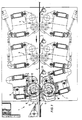
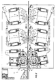
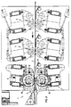
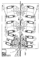
Bei der in Fig. 1 bis 7 dargestellten Ausführungsform sind die beiden Schneideinheiten 6, 7 übereinander angeordnet. Jede dieser Schneideinheiten ist schwenkbar gelagert, wozu eine Lagerung 12, 13 vorgesehen ist. Damit kann die obere Schneideinheit 6 in der Lagerung 12 um die Antriebswelle, und die untere Schneideinheit 7 in der Lagerung 13 um die Antriebswelle schwenken.In the embodiment shown in FIGS. 1 to 7, the two cutting
Die Wellpappenbahn 2 durchläuft in der in Fig. 1 dargestellten Lage die obere Schneideinheit 6, wobei sie auf der Gegenfläche 8 der oberen Schneideinheit 6 aufliegt und von dem Messer 11 dieser Schneideinheit bearbeitet wird. Die Bahn 2 kann dabei zusätzlich durch ortsfeste Führungen 20 abgestützt werden. Die untere Schneideinheit 7 ist außer Funktion. Sie läßt sich damit auf das neue gewünschte Format einstellen, und zwar dadurch, daß die Schneidwerkzeugkörper die Schneidmesser 10 entsprechend positioniert werden.The
Nach Fig. 2 bis 5 schwenkt die obere Schneideinheit 6 um einen geringen Winkelbetrag um die Lagerung 12 im Uhrzeigersinn. Entsprechend wird auch die auf der Gegenfläche 8 aufliegende Warenbahn 2 bewegt. Gleichzeitig schwenkt die untere Schneideinheit 7 im Uhrzeigersinn um die Lagerung 13. Dieser Schwenkvorgang erfolgt solange, bis die Position nach Fig. 5 erreicht ist.According to FIGS. 2 to 5, the
Nach Fig. 6 erfolgt eine Trennung der Warenbahn 2 durch einen nicht näher dargestellten Kurzquerschneider. Damit liegt die vordere Kante der neu zulaufenden Wellpappenbahn 2 im Bereich der Gegenfläche 9 der unteren Schneideinheit 7, so daß gemäß Fig 7 die untere Schneideinheit 7 mit neuem Format die Wellpappenbahn schneidet, wohingegen sich die obere Schneideinheit 6 nunmehr in Ruhestellung befindet.6, the
Die Rillwerkzeuge 3 und 4 wurden bereits bevor die Restbahn die Rillwerkzeuge verläßt, von der Bahn genommen, neu positioniert und wieder auf die neu ankommende Bahn gesetzt. Damit dies möglichst schnell erfolgt und maximal der letzte und der erste neue Bogen mit entsprechender Rillung versehen wird, sind die Rillwerkzeuge mit einer Schnellpositioniervorrichtung bestückt.The
Wie erkennbar, arbeiten beide Schneideinheiten, nämlich die obere Schneideinheit 6 und die untere Schneideinheit 7, immer abwechselnd, d.h. die obere Schneideinheit 6 arbeitet und die untere Schneideinheit 7 wird auf einen neuen Auftrag vorpositioniert und umgekehrt. Um mehr Nutzen schneiden zu können, ist es bei Tandembetrieb aber auch möglich, die Schneideinheiten gemeinsam einzusetzen.As can be seen, both cutting units, namely the
Bei Kurzquerschneiderschnitt oder auch bereits vorher bewegen sich beide Schneideinheiten 6, 7 synchron über einen Antrieb derart, daß die in Arbeit befindliche Schneideinheit mitsamt der darin durchlaufenden Wellpappenbahn 2 aus der horizontalen Arbeitsposition herausbewegt wird. Die Wellpappenbahn 2 nimmt hierbei keinen Schaden, da die Schwenkbewegung nur minimal ist.In the case of a short cross-section or even beforehand, both cutting
Kommt nun der die alte und die neue Bahn 2 trennende, durch einen der Schneid- und Rillmaschine 1 vorgelagerten Kurzquerschneider ausgeführten Kurzquerschneiderschnitt zu der betreffenden Schneideinheit, so läuft gemäß Fig. 6 und 7 die neu ankommende Bahn 2 automatisch in die neu voreingestellte untere Schneideinheit 7 bzw. umgekehrt. Die alte auslaufende Wellpappenbahn wird gänzlich von der oberen Schneideinheit 6 geschnitten. Diese obere Schneideinheit 6 ist damit frei und kann neu positioniert werden.If the short cross-section which separates the old and the
Derselbe Ablauf erfolgt beim Wechsel der unteren arbeitenden Schneideinheit 7 auf die obere vorpositionierte Schneideinheit 6. Da diese beiden Schneideinheiten 6 und 7 abwechselnd arbeiten, reicht eine relativ kleine Verstellgeschwindigkeit aus, um die Werkzeuge neu einzustellen.The same procedure takes place when changing the lower
Bei der Ausführungsform nach Fig. 1 bis 7 werden die beiden Schneideinheiten 6 und 7 jeweils um die Lagerung 12 bzw. 13 geschwenkt, wobei die um diese Lagerung schwenkbaren Gegenflächen 8 und 9 der jeweiligen Schneidwerkzeuge 6 und 7 als Führungsvorrichtung für die wechselweise Beschickung der Warenbahn 2 zu einer der Schneideinheiten 6, 7 dienen.In the embodiment according to FIGS. 1 to 7, the two cutting
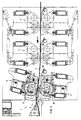
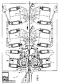
Bei der Ausführungsform nach Fig. 8 und 9 besteht alternativ die Möglichkeit, die obere und untere Schneideinheit 6, 7 in ihrer Mittelstellung festzumontieren und den Formatwechsel durch einen Führungstisch 14 vorzusehen, welcher vor den Schneideinheiten 6, 7 angeordnet ist. Dieser Führungsstisch 14 besteht aus zwei Platten 15 und 16, zwischen welchen die warenbahn 2 läuft. Beide Platten 15 und 16 sind jeweils mit einer Kolbenzylindereinheit 17 und 18 verbunden.In the embodiment according to FIGS. 8 and 9, it is alternatively possible to fix the upper and
Bei der Position nach Fig. 8 durchläuft die Wellpappenbahn 2 die untere Schneideinheit 7. Wird nun gemäß Fig. 9 der Führungstisch 14 mit Hilfe der Kolbenzylindereinheiten 17 und 18 verschwenkt, so wird die Warenbahn 2 nunmehr zu der oberen Schneideinheit 6 bewegt. Auch hierdurch ist eine wechselweise Beschickung der oberen und der unteren Schneideinheit 6 bzw. 7 bei Formatwechsel auf einfache Weise durchführbar. Wiederum sind die Rillwerkzeuge 3 und 4 mit einer entsprechenden Schnellpositioniervorrichtung bestückt, so daß diese Werkzeuge entsprechend schnell und einfach eingestellt werden können.8, the
Insgesamt ergibt sich damit eine Maschine, bei welcher der Formatwechsel ohne nennenswerte Restbahnbeschleunigung, ohne nennenswerte Lückenbildung der Warenbahn und ohne erheblichen Kostenaufwand durchzuführen ist. Weiterhin muß vorteilhafterweise zum Durchführen des Formatwechsels die erreichbare optimal hohe Produktionsgeschwindigkeit nicht verringert werden, so daß keine Qualitätsmängel hinsichtlich Verklebung und Geradheit der Wellpappe entstehen können.All in all, this results in a machine in which the format changeover without appreciable acceleration of the remaining web, without appreciable gap formation in the web and without significant cost is to be carried out. Furthermore, in order to carry out the format change, the achievable, optimally high production speed does not have to be reduced, so that there can be no quality defects with regard to gluing and straightness of the corrugated cardboard.
Claims (9)
mit einer den Rillwerkzeugen nachgeordneten Messersektion mit Schneidwerkzeugkörpern,
dadurch gekennzeichnet,
daß die Messersektion (5) aus mindestens zwei voneinander unabhängigen Schneideinheiten mit Schneidmesser (10, 11), Gegenfläche (8, 9) und voneinander unabhängig einstellbaren Schneidwerkzeugkörpern besteht, und
daß über mindestens eine Führungsvorrichtung die Warenbahn (2) wechselweise durch eine der Schneideinheiten (6, 7) geführt ist.Cutting and creasing machine for a web, in particular corrugated board
with a knife section downstream of the creasing tools with cutting tool bodies,
characterized by
that the knife section (5) consists of at least two mutually independent cutting units with a cutting knife (10, 11), counter surface (8, 9) and mutually independently adjustable cutting tool bodies, and
that the web (2) is alternately guided through one of the cutting units (6, 7) via at least one guide device.
Applications Claiming Priority (2)
| Application Number | Priority Date | Filing Date | Title |
|---|---|---|---|
| DE4226075 | 1992-08-06 | ||
| DE19924226075 DE4226075A1 (en) | 1992-08-06 | 1992-08-06 | Cutting and creasing machine for a web, in particular corrugated board |
Publications (1)
| Publication Number | Publication Date |
|---|---|
| EP0582074A1 true EP0582074A1 (en) | 1994-02-09 |
Family
ID=6465009
Family Applications (1)
| Application Number | Title | Priority Date | Filing Date |
|---|---|---|---|
| EP93109951A Withdrawn EP0582074A1 (en) | 1992-08-06 | 1993-06-22 | Slitter-scorer for a web, especially for a corrugated cardboard web |
Country Status (2)
| Country | Link |
|---|---|
| EP (1) | EP0582074A1 (en) |
| DE (1) | DE4226075A1 (en) |
Cited By (3)
| Publication number | Priority date | Publication date | Assignee | Title |
|---|---|---|---|---|
| WO1995024298A1 (en) * | 1994-03-10 | 1995-09-14 | Marquip, Inc. | Paper and paperboard web slitting apparatus and method |
| EP0896864A2 (en) * | 1997-06-18 | 1999-02-17 | Fosber S.P.A. | Device and method for the slitting of a web and slitter/scorer machine incorporating said device |
| CN102922775A (en) * | 2011-08-10 | 2013-02-13 | 广州市益佳昌盛自动化科技有限公司 | Automatic paper feed digital cropping and creasing machine |
Families Citing this family (1)
| Publication number | Priority date | Publication date | Assignee | Title |
|---|---|---|---|---|
| DE19754799A1 (en) * | 1997-12-10 | 1999-06-17 | Bhs Corr Masch & Anlagenbau | Slitting and creasing machine for corrugated cardboard webs |
Citations (4)
| Publication number | Priority date | Publication date | Assignee | Title |
|---|---|---|---|---|
| FR1333419A (en) * | 1962-09-11 | 1963-07-26 | Simon Ltd Henry | Machine for the production of cardboard boxes |
| FR2244620A1 (en) * | 1973-09-21 | 1975-04-18 | Rengo Co Ltd | |
| FR2391040A1 (en) * | 1977-05-17 | 1978-12-15 | Peters W Maschf | MACHINE FOR LONG-CUTTING AND LONGITUDINAL GROOVING OR CANNELING STRIPS OF MATERIAL, IN PARTICULAR CORRUGATED CARDBOARD |
| GB2049529A (en) * | 1979-05-09 | 1980-12-31 | Rengo Co Ltd | Slitterscorer apparatus |
Family Cites Families (2)
| Publication number | Priority date | Publication date | Assignee | Title |
|---|---|---|---|---|
| DE3202914C2 (en) * | 1982-01-29 | 1984-04-19 | BHS-Bayerische Berg-, Hütten- und Salzwerke AG, 8000 München | Longitudinal cutting and / or creasing machine for moving material webs, in particular for corrugated cardboard webs |
| DE3826993A1 (en) * | 1988-08-09 | 1990-02-15 | Bhs Bayerische Berg | LENGTH CUTTING AND / OR Creasing machine for moving material webs, especially for corrugated cardboard webs |
-
1992
- 1992-08-06 DE DE19924226075 patent/DE4226075A1/en not_active Withdrawn
-
1993
- 1993-06-22 EP EP93109951A patent/EP0582074A1/en not_active Withdrawn
Patent Citations (4)
| Publication number | Priority date | Publication date | Assignee | Title |
|---|---|---|---|---|
| FR1333419A (en) * | 1962-09-11 | 1963-07-26 | Simon Ltd Henry | Machine for the production of cardboard boxes |
| FR2244620A1 (en) * | 1973-09-21 | 1975-04-18 | Rengo Co Ltd | |
| FR2391040A1 (en) * | 1977-05-17 | 1978-12-15 | Peters W Maschf | MACHINE FOR LONG-CUTTING AND LONGITUDINAL GROOVING OR CANNELING STRIPS OF MATERIAL, IN PARTICULAR CORRUGATED CARDBOARD |
| GB2049529A (en) * | 1979-05-09 | 1980-12-31 | Rengo Co Ltd | Slitterscorer apparatus |
Cited By (6)
| Publication number | Priority date | Publication date | Assignee | Title |
|---|---|---|---|---|
| WO1995024298A1 (en) * | 1994-03-10 | 1995-09-14 | Marquip, Inc. | Paper and paperboard web slitting apparatus and method |
| EP0896864A2 (en) * | 1997-06-18 | 1999-02-17 | Fosber S.P.A. | Device and method for the slitting of a web and slitter/scorer machine incorporating said device |
| EP0896864A3 (en) * | 1997-06-18 | 1999-12-01 | Fosber S.P.A. | Device and method for the slitting of a web and slitter/scorer machine incorporating said device |
| US6165117A (en) * | 1997-06-18 | 2000-12-26 | Fosber, S.P.A. | Device and method for the slitting of a web and slitter/scorer machine incorporating said device |
| CN102922775A (en) * | 2011-08-10 | 2013-02-13 | 广州市益佳昌盛自动化科技有限公司 | Automatic paper feed digital cropping and creasing machine |
| CN102922775B (en) * | 2011-08-10 | 2016-01-20 | 广州市益佳昌盛自动化科技有限公司 | Automatic paper feed number cuts marking press |
Also Published As
| Publication number | Publication date |
|---|---|
| DE4226075A1 (en) | 1994-02-24 |
Similar Documents
| Publication | Publication Date | Title |
|---|---|---|
| DE602004005762T2 (en) | Method for controlling a cutting and creasing machine | |
| EP0236275B2 (en) | Apparatus and process for cutting rectangular pieces from a web | |
| DE2701068A1 (en) | SLOTING DEVICE FOR RAIL-SHAPED MATERIAL | |
| DE60110161T2 (en) | Device and method for format change in a system for cross-cutting web-like materials | |
| DE4425155A1 (en) | Plant for the production of corrugated cardboard sheets with changeable format | |
| EP0289878B1 (en) | Method and device for cutting complex shaped labels | |
| EP0243748B1 (en) | Device for winding up several small webs after longitudinally slitting a large web | |
| DE1957350B2 (en) | DIVIDING MACHINE, IN PARTICULAR COLORFUL DIVIDING MACHINE | |
| EP0595253B1 (en) | Device for fly cutting of fine material by laser irradition | |
| EP0204866A1 (en) | Transverse cutter for moving webs | |
| DE3017872C2 (en) | Slitting and notching device | |
| DE2055313A1 (en) | Device for guiding and carrying a plurality of belts or webs moving parallel to one another, in particular for webs of corrugated cardboard to be divided | |
| DE2638735A1 (en) | POSITIONING DEVICE | |
| DE2722233C3 (en) | ||
| EP0692370B1 (en) | Installation with coating and pivoting cutter for manufacturing corrugated paperboard with variable format | |
| EP0582074A1 (en) | Slitter-scorer for a web, especially for a corrugated cardboard web | |
| DE8132018U1 (en) | "MACHINE FOR LENGTH CUTTING AND CURLING OF A MATERIAL RAIL, IN PARTICULAR CORRUGATED CARDBOARD" | |
| DE2628728A1 (en) | CUTTING DEVICE WITH ROTATING FLYING KNIVES FOR THE PRODUCTION OF MOLDING CUTS IN THE EDGES OF MOVING MATERIAL SHEETS | |
| EP0957057A2 (en) | Longitudinal folding device for the folding apparatus of rotary printing machines | |
| DE3636685A1 (en) | Cutting wide strip of material into narrow strips - involves machine which winds narrow strips onto separate reels | |
| DE933073C (en) | Device for cutting boards or sheets from continuous webs, in particular cardboard, paper or the like | |
| DE10129429C2 (en) | Device for cutting a web-shaped workpiece | |
| DE3635638C1 (en) | One-sided corrugated-board machine | |
| EP0169962A1 (en) | Longitudinal cutter installed in a rolling mill between plate-trimming shears and a cross cutter | |
| EP3025803B1 (en) | Drive device for a machine tool and machine tool with such a drive device |
Legal Events
| Date | Code | Title | Description |
|---|---|---|---|
| PUAI | Public reference made under article 153(3) epc to a published international application that has entered the european phase |
Free format text: ORIGINAL CODE: 0009012 |
|
| AK | Designated contracting states |
Kind code of ref document: A1 Designated state(s): DE FR GB IT |
|
| STAA | Information on the status of an ep patent application or granted ep patent |
Free format text: STATUS: THE APPLICATION IS DEEMED TO BE WITHDRAWN |
|
| 18D | Application deemed to be withdrawn |
Effective date: 19940810 |