EP0228519A1 - Vorrichtung zur Nassbehandlung von Schlauchware - Google Patents
Vorrichtung zur Nassbehandlung von Schlauchware Download PDFInfo
- Publication number
- EP0228519A1 EP0228519A1 EP86114366A EP86114366A EP0228519A1 EP 0228519 A1 EP0228519 A1 EP 0228519A1 EP 86114366 A EP86114366 A EP 86114366A EP 86114366 A EP86114366 A EP 86114366A EP 0228519 A1 EP0228519 A1 EP 0228519A1
- Authority
- EP
- European Patent Office
- Prior art keywords
- rollers
- pressure rollers
- outer pressure
- hose
- spreader
- Prior art date
- Legal status (The legal status is an assumption and is not a legal conclusion. Google has not performed a legal analysis and makes no representation as to the accuracy of the status listed.)
- Granted
Links
Images
Classifications
-
- D—TEXTILES; PAPER
- D06—TREATMENT OF TEXTILES OR THE LIKE; LAUNDERING; FLEXIBLE MATERIALS NOT OTHERWISE PROVIDED FOR
- D06C—FINISHING, DRESSING, TENTERING OR STRETCHING TEXTILE FABRICS
- D06C5/00—Shaping or stretching of tubular fabrics upon cores or internal frames
Definitions
- the invention relates to a device (according to the preamble of claim 1) for wet treatment, in particular for dyeing, of continuously moving tubular goods.
- the tubular goods first penetrate a foulard chassis.
- the tubular fabric loaded with dye liquor is then inflated to a balloon by introducing a gaseous medium, the pores of the fabric remaining closed by the liquor.
- the tubular goods then pass through a pair of rollers that retain the gas atmosphere in the balloon.
- the tubular fabric then passes through another foulard, which holds back the carried fleet.
- a disadvantage of this known device is that the pinch process in the foulard results in a certain bow marking, which affects the uniformity of the color.
- the invention is therefore based on the object of designing a device of the type required in the preamble of claim 1 in such a way that any bow marking is avoided and thus a particularly uniform loss of goods is achieved.
- the outer pressure rollers provided according to the invention act together with the tube spreader on the area of the tube material which forms the bow zone when passing through the foulard squeeze rollers. A bow marking caused in this area by the foulard squeeze rollers is consequently reliably eliminated by the interaction of the hose spreader with the two outer pressure rollers.
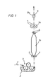
- the device for wet treatment illustrated in FIG. 1, in particular for dyeing continuously moving tubular fabric 1, contains a trough 2 with a squeeze unit 3 in which the tubular fabric 1 receives dyeing liquor.
- the tubular fabric 1 then passes through a nozzle 4, through which a gaseous medium (such as air, nitrogen, steam) is introduced into the tubular fabric 1 and is thus inflated to a balloon 1a.
- a gaseous medium such as air, nitrogen, steam
- a rotatable counter roller 5 is arranged on the side opposite the nozzle 4.
- the nozzle 4 can also be designed to be rotatable, so that it exerts only minimal friction on the tubular fabric 1.
- a pair of rollers 6 is arranged, which retains the gas atmosphere present in the balloon 1a.
- the tubular fabric 1 then passes through a foulard, which is formed by two rubber-coated squeeze rollers 7. These squeeze rollers 7 hold the fleet carried along by the tubular goods 1 back, which accordingly flows back over the circumference of the balloon 1a into the trough 2. As a result, the surface of the balloon 1a is covered with a uniform liquor film, which is essential for achieving good coloring quality.
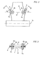
- a hose spreader 8 and pressure rollers 9 are provided in the direction of movement of the tubular fabric 1 behind the squeeze rollers 7 - in the illustrated vertical guidance of the tubular fabric 1 thus above the squeeze rollers 7 - as can be seen in detail from FIGS. 2 and 3.
- the tube spreader 8 is essentially formed by two rings 8a, 8b rotatably arranged in the tube material 1, which are held by means of bearing projections 10a, 11a and 10b, 11b arranged outside the tube material 1.
- the bearing protrusions 10a, 10b sit on a spindle 12 and the bearing protrusions 11a, 11b on a spindle 13.
- the distance between the bearing protrusions 10a, 10b or 11a, 11b and thus the distance between the two rings 8a can be adjusted , 8b to the respective diameter of the tubular goods 1.
- the axes 9a of the pressure rollers 9 are perpendicular to the axes 7a of the squeeze rollers 7.
- the outer pressure rollers 9 consequently act on the two Zones of the tubular goods 1, in which a bow marking has formed when passing through the nip rollers 7.
- the outer pressure rollers 9 By the interaction of the outer pressure rollers 9 with the hose spreader 8 formed by the rings 8a, 8b, two small pinch joints are thus formed, which serve to even out or remove the bow marking.
- the two outer pressure rollers 9 are expediently adjustable in the direction of movement of the tubular goods 1 (arrow 14).
- the outer pressure rollers 9 are also expediently adjustable together with the tubular spreader 8.
- the rings 8a, 8b of the tube spreader 8 have a circular cross section.
- the outer pressure rollers 9 are provided with a concave outer contour which is adapted to the cross-sectional profile of the rings 8a, 8b.
- the material of the outer pressure rollers 9 is expediently softer than the material of the rings 8a, 8b of the hose spreader 8.
Landscapes
- Engineering & Computer Science (AREA)
- Textile Engineering (AREA)
- Treatment Of Fiber Materials (AREA)
- Processing And Handling Of Plastics And Other Materials For Molding In General (AREA)
Abstract
Description
- Die Erfindung betrifft eine Vorrichtung (entsprechend dem Oberbegriff des Anspruches 1) zur Naßbehandlung, insbesondere zum Färben, von kontinuierlich bewegter Schlauchware.
- Bei einer bekannten Vorrichtung dieser Art durchsetzt die Schlauchware zunächst ein Foulard-Chassis. Die mit Färbeflotte beladene Schlauchware wird anschließend durch Einführen eines gasförmigen Mediums zu einem Ballon aufgeblasen, wobei die Poren der Ware durch die Flotte geschlossen bleiben. Die Schlauchware passiert dann ein Walzenpaar, das die im Ballon vorhandene Gasatmosphäre zurückhält. Anschließend durchsetzt die Schlauchware einen weiteren Foulard, der die mitgeführte Flotte zurückhält.
- Ein Nachteil dieser bekannten Vorrichtung besteht darin, daß sich durch den Quetschprozeß im Foulard eine gewisse Bugmarkierung ergibt, was die Gleichmäßigkeit der Färbung beeinträchtigt.
- Der Erfindung liegt daher die Aufgabe zugrunde, eine Vorrichtung der im Oberbegriff des Anspruches 1 vorausgesetzten Art so auszubilden, daß jegliche Bugmarkierung vermieden und damit ein besonders gleichmäßiger Warenausfall erreicht wird.
- Diese Aufgabe wird erfindungsgemäß durch das kennzeichnende Merkmal des Anspruches 1 gelöst.
- Die erfindungsgemäß vorgesehenen äußeren Andrückrollen wirken zusammen mit dem Schlauchbreithalter auf den Bereich der Schlauchware ein, der beim Passieren der Foulard-Quetschwalzen die Bugzone bildet. Eine in diesem Bereich durch die Foulard-Quetschwalzen verursachte Bugmarkierung wird infolgedessen durch das Zusammenwirken des Schlauchbreithalters mit den beiden äußeren Andrückrollen zuverlässig beseitigt.
- Die beiden äußeren Andrückrollen bilden zusammen mit dem Schlauchbreithalter eine dem Foulard nachgeschaltete, zusätzliche kleine Quetschfuge, die im Bereich einer etwa vorhandenen Bugmarkierung die notwendige Vergleichmäßigung der Warenbehandlung bewirkt und damit eine hohe Egalität des Warenausfalls gewährleistet.
- Zweckmäßige Ausgestaltungen der Erfindung sind Gegenstand der Unteransprüche und werden im Zusammenhang mit der Beschreibung eines in der Zeichnung veranschaulichten Ausführungsbeispieles erläutert.
- In der Zeichnung zeigen


- Die in Fig.1 veranschaulichte Vorrichtung zur Naßbehandlung, insbesondere zum Färben von kontinuierlich bewegter Schlauchware 1 enthält einen Trog 2 mit einem Unterflottenquetschwerk 3, in dem die Schlauchware 1 Färbeflotte aufnimmt.
- Die Schlauchware 1 passiert sodann eine Düse 4, durch die ein gasförmiges Medium (wie Luft, Stickstoff, Dampf) in die Schlauchware 1 eingeführt und diese damit zu einem Ballon 1a aufgeblasen wird. Auf der der Düse 4 gegenüberliegenden Seite ist eine drehbare Gegenwalze 5 angeordnet. Auch die Düse 4 kann drehbar ausgebildet sein, so daß sie nur eine minimale Reibung auf die Schlauchware 1 ausübt.
- Am Ende der Ballonstrecke ist ein Walzenpaar 6 angeordnet, das die im Ballon 1a vorhandene Gasatmosphäre zurückhält.
- Die Schlauchware 1 durchsetzt dann einen Foulard, der von zwei mit Gummi überzogenen Quetschwalzen 7 gebildet wird. Diese Quetschwalzen 7 halten die von der Schlauchware 1 mitgeführte Flotte zurück, die demgemäß über den Umfang des Ballons 1a zurück in den Trog 2 strömt. Die Oberfläche des Ballons 1a ist infolgedessen mit einem gleichmäßigen Flottenfilm überzogen, was für die Erzielung einer guten Färbequalität wesentlich ist.
- In Bewegungsrichtung der Schlauchware 1 hinter den Quetschwalzen 7 - bei der dargestellten Vertikalführung der Schlauchware 1 somit über den Quetschwalzen 7 - sind ein Schlauchbreithalter 8 sowie Andrückrollen 9 vorgesehen, wie im einzelnen aus den Fig.2 und 3 hervorgeht.
- Der Schlauchbreithalter 8 wird im wesentlichen durch zwei in der Schlauchware 1 drehbar angeordnete Ringe 8a, 8b gebildet, die mittels außerhalb der Schlauchware 1 angeordneter Lagerungsvorsprünge 10a, 11a bzw. 10b, 11b gehalten sind. Die Lagerungsvorsprünge 10a, 10b sitzen auf einer Spindel 12 und die Lagerungsvorsprünge 11a, 11b auf einer Spindel 13. Durch Verstellung der Spindeln 12, 13 läßt sich der Abstand der Lagerungsvorsprünge 10a, 10b bzw. 11a, 11b und damit der Abstand der beiden Ringe 8a, 8b dem jeweiligen Durchmesser der Schlauchware 1 anpassen.
- Wie die Zeichnung erkennen läßt, verlaufen die Achsen 9a der Andrückrollen 9 senkrecht zu den Achsen 7a der Quetschwalzen 7. Die äußeren Andrückrollen 9 wirken infolgedessen auf die beiden Zonen der Schlauchware 1 ein, in denen sich beim Passieren der Quetschwalzen 7 eine Bugmarkierung gebildet hat. Durch das Zusammenwirken der äußeren Andrückrollen 9 mit dem von den Ringen 8a, 8b gebildeten Schlauchbreithalter 8 werden somit zwei kleine Quetschfugen gebildet, die zur Vergleichmäßigung bzw. Beseitigung der Bugmarkierung dienen.
- Zur Anpassung an die jeweiligen Art der Schlauchware 1 und deren Transportgeschwindigkeit sind die beiden äußeren Andrückrollen 9 zweckmäßig in Bewegungsrichtung der Schlauchware 1 verstellbar (Pfeil 14). Zur Anpassung an die jeweilige Breite der Schlauchware 1 sind die äußeren Andrückrollen 9 außerdem zweckmäßig gemeinsam mit dem Schlauchbreithalter 8 verstellbar.
- Wie Fig.3 erkennen läßt, besitzen die Ringe 8a, 8b des Schlauchbreithalters 8 einen kreisförmigen Querschnitt. Die äußeren Andrückrollen 9 sind mit einer konkaven Außenkontur versehen, die dem Querschnittsprofil der Ringe 8a, 8b angepaßt ist.
- Das Material der äußeren Andrückrollen 9 ist zweckmäßig weicher als das Material der Ringe 8a, 8b des Schlauchbreithalters 8.
- Wie die der Erfindung zugrundeliegenden Versuche bestätigten, läßt sich durch die erfindungsgemäße Vorrichtung die in den Foulard-Quetschwalzen 7 gebildete Bugmarkierung der Schlauchware 1 zuverlässig beseitigen.
- Zweckmäßig ist nicht nur die Berührungszone der äußeren Andrückrollen 9 , sondern auch der Berührungsdruck einstellbar, um je nach Art der Ware und der in den Foulard-Quetschwalzen 7 entstandenen Bugmarkierung einen optimalen Vergleichmäßigungseffekt zu erzielen.
Claims (8)
daß in Bewegungsrichtung der Ware (1) hinter den Quetschwalzen (7) ein Schlauchbreithalter (8) sowie zwei mit dem Schlauchbreithalter (8) zusammenwirkende, zur Vergleichmäßigung der Bugmarkierung dienende äußere Andrückrollen (9) angeordnet sind.
Applications Claiming Priority (2)
| Application Number | Priority Date | Filing Date | Title |
|---|---|---|---|
| DE3600559 | 1986-01-10 | ||
| DE19863600559 DE3600559A1 (de) | 1986-01-10 | 1986-01-10 | Vorrichtung zur nassbehandlung von schlauchware |
Publications (2)
| Publication Number | Publication Date |
|---|---|
| EP0228519A1 true EP0228519A1 (de) | 1987-07-15 |
| EP0228519B1 EP0228519B1 (de) | 1989-04-05 |
Family
ID=6291646
Family Applications (1)
| Application Number | Title | Priority Date | Filing Date |
|---|---|---|---|
| EP86114366A Expired EP0228519B1 (de) | 1986-01-10 | 1986-10-16 | Vorrichtung zur Nassbehandlung von Schlauchware |
Country Status (3)
| Country | Link |
|---|---|
| EP (1) | EP0228519B1 (de) |
| DE (2) | DE3600559A1 (de) |
| ES (1) | ES2008076B3 (de) |
Cited By (1)
| Publication number | Priority date | Publication date | Assignee | Title |
|---|---|---|---|---|
| WO2009074144A1 (de) | 2007-12-12 | 2009-06-18 | Lindauer Dornier Gesellschaft Mbh | Verfahren zum färben eines schlauches aus einem textilmaterial und färbemaschine zur durchführung des verfahrens |
Families Citing this family (5)
| Publication number | Priority date | Publication date | Assignee | Title |
|---|---|---|---|---|
| SE8800609D0 (sv) * | 1988-02-19 | 1988-02-19 | Iro Ab | Anordning for hydro-extraktion av slangvara |
| DE4123477C2 (de) * | 1991-07-16 | 1994-08-25 | Dornier Gmbh Lindauer | Verfahren zur Vermeidung von Bugmarkierungen in Schlauch-Wirkware und Vorrichtung zur Durchführung des Verfahrens |
| ATE395454T1 (de) * | 2003-11-17 | 2008-05-15 | Suchy Textilmaschb Gmbh | Verfahren und vorrichtung zur behandlung von textilen materialien in schlauchform, beispielsweise rundgestricke |
| DE102004053531B4 (de) * | 2004-11-05 | 2007-01-11 | Suchy Textilmaschinenbau Gmbh | Vorrichtung zum kontinuierlichen Färben von textilen Materialien in Schlauchform |
| DE102005027730B3 (de) * | 2005-06-16 | 2006-10-26 | Lindauer Dornier Gmbh | Verfahren und Vorrichtung zum Beseitigen von Bugmarkierungen in schlauchförmigen Maschenware, die aus einem Anteil natürlicher Fasern und aus einem Anteil elastischer, synthetischer Fasern besteht |
Citations (3)
| Publication number | Priority date | Publication date | Assignee | Title |
|---|---|---|---|---|
| US3508286A (en) * | 1967-05-10 | 1970-04-28 | Curt L Nyman | Method and a device for withdrawing from a liquid bath,normalizing and arranging in mesh alignment a knitted hose or the like |
| US4112532A (en) * | 1976-11-05 | 1978-09-12 | Frank Catallo | Method of padding and extracting a continuously advancing circular knit fabric tube |
| EP0166316A1 (de) * | 1984-06-20 | 1986-01-02 | BASF Aktiengesellschaft | Verfahren zur Beseitigung der Bugmarkierung bei Maschenware in Schlauchform sowie eine Vorrichtung zur Durchführung des Verfahrens |
Family Cites Families (4)
| Publication number | Priority date | Publication date | Assignee | Title |
|---|---|---|---|---|
| DE1922938A1 (de) * | 1969-05-06 | 1970-11-19 | Groezinger Maschf Arbach | Breithalter zur Behandlung von Schlauchware |
| US3978557A (en) * | 1975-05-12 | 1976-09-07 | Goodson Sam M | Apparatus for spreading and guiding a tubular fabric |
| DE2926442A1 (de) * | 1979-06-29 | 1981-01-22 | Thies Gmbh & Co | Vorrichtung zum spannungslosen und faltenfreien ausbreiten textiler flaechengebilde in schlauchform |
| GB2154255A (en) * | 1984-02-16 | 1985-09-04 | Calator Ab | Treating material webs with liquid |
-
1986
- 1986-01-10 DE DE19863600559 patent/DE3600559A1/de not_active Withdrawn
- 1986-10-16 ES ES86114366T patent/ES2008076B3/es not_active Expired
- 1986-10-16 DE DE8686114366T patent/DE3662703D1/de not_active Expired
- 1986-10-16 EP EP86114366A patent/EP0228519B1/de not_active Expired
Patent Citations (3)
| Publication number | Priority date | Publication date | Assignee | Title |
|---|---|---|---|---|
| US3508286A (en) * | 1967-05-10 | 1970-04-28 | Curt L Nyman | Method and a device for withdrawing from a liquid bath,normalizing and arranging in mesh alignment a knitted hose or the like |
| US4112532A (en) * | 1976-11-05 | 1978-09-12 | Frank Catallo | Method of padding and extracting a continuously advancing circular knit fabric tube |
| EP0166316A1 (de) * | 1984-06-20 | 1986-01-02 | BASF Aktiengesellschaft | Verfahren zur Beseitigung der Bugmarkierung bei Maschenware in Schlauchform sowie eine Vorrichtung zur Durchführung des Verfahrens |
Cited By (1)
| Publication number | Priority date | Publication date | Assignee | Title |
|---|---|---|---|---|
| WO2009074144A1 (de) | 2007-12-12 | 2009-06-18 | Lindauer Dornier Gesellschaft Mbh | Verfahren zum färben eines schlauches aus einem textilmaterial und färbemaschine zur durchführung des verfahrens |
Also Published As
| Publication number | Publication date |
|---|---|
| DE3600559A1 (de) | 1987-07-16 |
| EP0228519B1 (de) | 1989-04-05 |
| DE3662703D1 (en) | 1989-05-11 |
| ES2008076B3 (es) | 1989-07-16 |
Similar Documents
| Publication | Publication Date | Title |
|---|---|---|
| DE1078527B (de) | Vierwalzenfoulard | |
| DE2101228A1 (de) | Vorrichtung zum Ändern der Bewegungsrichtung von kontinuierlich bewegtem, bahnförmigem Gut | |
| EP0228519B1 (de) | Vorrichtung zur Nassbehandlung von Schlauchware | |
| DE19634448A1 (de) | Verfahren und Vorrichtung zum Auftragen eines flüssigen oder pastösen Mediums auf eine laufende Materialbahn | |
| DE3201590A1 (de) | Maschine zum walken, waschen und vortrocknen eines textilstranges | |
| DE2222389A1 (de) | Vorrichtung zum Behandeln einer laufenden Bahn | |
| DE2822214A1 (de) | Vorrichtung zum hindurchfuehren eines arbeitsmediums durch eine kontinuierlich bewegte, durchlaessige warenbahn | |
| DE2140612A1 (de) | Verfahren zur behandlung oder ausruestung von stoff und vorrichtung zur ausfuehrung des verfahrens | |
| DE2935374B1 (de) | Von aussen gehaltener zylindrischer Breithalter fuer Schlauchware | |
| DE3033478C2 (de) | Foulard mit einer Umschlingungswalze für eine zu behandelnde textile Warenbahn | |
| DE4012176C2 (de) | Vorrichtung zum Behandeln einer beschichteten Substratbahn | |
| DE4123477A1 (de) | Verfahren zur vermeidung von bugmarkierungen in schlauch-wirkware und vorrichtung zur durchfuehrung des verfahrens | |
| DE3120042A1 (de) | Verfahren und vorrichtung zum impraegnieren von nass vorbehandelten warenbahnen, insbes. gewirke und gestricke, mit faerbeflotten und/oder chemikalien | |
| DE3127916A1 (de) | "vorrichtung zur nassbehandlung von geweben" | |
| DE4408416A1 (de) | Vorrichtung zum Aufwickeln einer textilen Warenbahn | |
| DE940105C (de) | Foulard | |
| DE2752011C3 (de) | Vorrichtung zur kontinuierlichen NaBbehandlung, insbesondere zum Färben und Imprägnieren einer Textilbahn | |
| DE3701670A1 (de) | Auftragswerk zur beschichtung und befeuchtung laufender warenbahnen | |
| DE26870C (de) | Stoffquetsch-und Wringmaschine, auch als Stoff-Waschmaschine verwendbar | |
| DE3112161A1 (de) | Mit rotierender schablone oder sieb arbeitende auftragsstation | |
| DE2133123A1 (de) | Vorrichtung zum Behandeln von flaechigem Stueckgut mit fluessigen Substanzen | |
| DE2149595A1 (de) | Breitausruestungsmaschine insbesondere faerbejigger | |
| DE2200312B2 (de) | Vorrichtung zum waschen von textilen warenbahnen | |
| DE6918236U (de) | Breithalter zur behandlung von schlauchware. | |
| DE1922938A1 (de) | Breithalter zur Behandlung von Schlauchware |
Legal Events
| Date | Code | Title | Description |
|---|---|---|---|
| PUAI | Public reference made under article 153(3) epc to a published international application that has entered the european phase |
Free format text: ORIGINAL CODE: 0009012 |
|
| AK | Designated contracting states |
Kind code of ref document: A1 Designated state(s): CH DE ES FR IT LI SE |
|
| 17P | Request for examination filed |
Effective date: 19870908 |
|
| 17Q | First examination report despatched |
Effective date: 19880803 |
|
| GRAA | (expected) grant |
Free format text: ORIGINAL CODE: 0009210 |
|
| ITF | It: translation for a ep patent filed |
Owner name: ING. FERRAROTTI GIOVANNI |
|
| AK | Designated contracting states |
Kind code of ref document: B1 Designated state(s): CH DE ES FR IT LI SE |
|
| REF | Corresponds to: |
Ref document number: 3662703 Country of ref document: DE Date of ref document: 19890511 |
|
| ET | Fr: translation filed | ||
| PLBE | No opposition filed within time limit |
Free format text: ORIGINAL CODE: 0009261 |
|
| STAA | Information on the status of an ep patent application or granted ep patent |
Free format text: STATUS: NO OPPOSITION FILED WITHIN TIME LIMIT |
|
| 26N | No opposition filed | ||
| ITTA | It: last paid annual fee | ||
| PGFP | Annual fee paid to national office [announced via postgrant information from national office to epo] |
Ref country code: FR Payment date: 19920907 Year of fee payment: 7 |
|
| PGFP | Annual fee paid to national office [announced via postgrant information from national office to epo] |
Ref country code: SE Payment date: 19920914 Year of fee payment: 7 |
|
| PGFP | Annual fee paid to national office [announced via postgrant information from national office to epo] |
Ref country code: CH Payment date: 19920915 Year of fee payment: 7 |
|
| PGFP | Annual fee paid to national office [announced via postgrant information from national office to epo] |
Ref country code: ES Payment date: 19921014 Year of fee payment: 7 |
|
| PGFP | Annual fee paid to national office [announced via postgrant information from national office to epo] |
Ref country code: DE Payment date: 19921215 Year of fee payment: 7 |
|
| PG25 | Lapsed in a contracting state [announced via postgrant information from national office to epo] |
Ref country code: SE Effective date: 19931017 Ref country code: ES Free format text: LAPSE BECAUSE OF NON-PAYMENT OF DUE FEES Effective date: 19931017 |
|
| PG25 | Lapsed in a contracting state [announced via postgrant information from national office to epo] |
Ref country code: LI Effective date: 19931031 Ref country code: CH Effective date: 19931031 |
|
| PG25 | Lapsed in a contracting state [announced via postgrant information from national office to epo] |
Ref country code: FR Effective date: 19940630 |
|
| REG | Reference to a national code |
Ref country code: CH Ref legal event code: PL |
|
| PG25 | Lapsed in a contracting state [announced via postgrant information from national office to epo] |
Ref country code: DE Effective date: 19940701 |
|
| REG | Reference to a national code |
Ref country code: FR Ref legal event code: ST |
|
| EUG | Se: european patent has lapsed |
Ref document number: 86114366.7 Effective date: 19940510 |
|
| REG | Reference to a national code |
Ref country code: ES Ref legal event code: FD2A Effective date: 19941112 |
|
| PG25 | Lapsed in a contracting state [announced via postgrant information from national office to epo] |
Ref country code: IT Free format text: LAPSE BECAUSE OF NON-PAYMENT OF DUE FEES;WARNING: LAPSES OF ITALIAN PATENTS WITH EFFECTIVE DATE BEFORE 2007 MAY HAVE OCCURRED AT ANY TIME BEFORE 2007. THE CORRECT EFFECTIVE DATE MAY BE DIFFERENT FROM THE ONE RECORDED. Effective date: 20051016 |