EP0200744B2 - Scharnier - Google Patents
Scharnier Download PDFInfo
- Publication number
- EP0200744B2 EP0200744B2 EP85905043A EP85905043A EP0200744B2 EP 0200744 B2 EP0200744 B2 EP 0200744B2 EP 85905043 A EP85905043 A EP 85905043A EP 85905043 A EP85905043 A EP 85905043A EP 0200744 B2 EP0200744 B2 EP 0200744B2
- Authority
- EP
- European Patent Office
- Prior art keywords
- base plate
- hinge
- hinge arm
- arm
- holding
- Prior art date
- Legal status (The legal status is an assumption and is not a legal conclusion. Google has not performed a legal analysis and makes no representation as to the accuracy of the status listed.)
- Expired - Lifetime
Links
- 238000003825 pressing Methods 0.000 abstract description 2
- 238000004873 anchoring Methods 0.000 description 3
- 238000010276 construction Methods 0.000 description 2
- 230000015572 biosynthetic process Effects 0.000 description 1
- 210000003462 vein Anatomy 0.000 description 1
Images


Classifications
-
- E—FIXED CONSTRUCTIONS
- E05—LOCKS; KEYS; WINDOW OR DOOR FITTINGS; SAFES
- E05D—HINGES OR SUSPENSION DEVICES FOR DOORS, WINDOWS OR WINGS
- E05D7/00—Hinges or pivots of special construction
-
- E—FIXED CONSTRUCTIONS
- E05—LOCKS; KEYS; WINDOW OR DOOR FITTINGS; SAFES
- E05D—HINGES OR SUSPENSION DEVICES FOR DOORS, WINDOWS OR WINGS
- E05D7/00—Hinges or pivots of special construction
- E05D7/04—Hinges adjustable relative to the wing or the frame
- E05D7/0407—Hinges adjustable relative to the wing or the frame the hinges having two or more pins and being specially adapted for cabinets or furniture
-
- E—FIXED CONSTRUCTIONS
- E05—LOCKS; KEYS; WINDOW OR DOOR FITTINGS; SAFES
- E05D—HINGES OR SUSPENSION DEVICES FOR DOORS, WINDOWS OR WINGS
- E05D7/00—Hinges or pivots of special construction
- E05D7/12—Hinges or pivots of special construction to allow easy detachment of the hinge from the wing or the frame
- E05D7/123—Hinges or pivots of special construction to allow easy detachment of the hinge from the wing or the frame specially adapted for cabinets or furniture
- E05D7/125—Hinges or pivots of special construction to allow easy detachment of the hinge from the wing or the frame specially adapted for cabinets or furniture the hinge having two or more pins
-
- E—FIXED CONSTRUCTIONS
- E05—LOCKS; KEYS; WINDOW OR DOOR FITTINGS; SAFES
- E05D—HINGES OR SUSPENSION DEVICES FOR DOORS, WINDOWS OR WINGS
- E05D5/00—Construction of single parts, e.g. the parts for attachment
- E05D5/02—Parts for attachment, e.g. flaps
- E05D5/0276—Parts for attachment, e.g. flaps for attachment to cabinets or furniture, the hinge having two or more pins
-
- E—FIXED CONSTRUCTIONS
- E05—LOCKS; KEYS; WINDOW OR DOOR FITTINGS; SAFES
- E05Y—INDEXING SCHEME ASSOCIATED WITH SUBCLASSES E05D AND E05F, RELATING TO CONSTRUCTION ELEMENTS, ELECTRIC CONTROL, POWER SUPPLY, POWER SIGNAL OR TRANSMISSION, USER INTERFACES, MOUNTING OR COUPLING, DETAILS, ACCESSORIES, AUXILIARY OPERATIONS NOT OTHERWISE PROVIDED FOR, APPLICATION THEREOF
- E05Y2600/00—Mounting or coupling arrangements for elements provided for in this subclass
- E05Y2600/50—Mounting methods; Positioning
- E05Y2600/52—Toolless
- E05Y2600/53—Snapping
-
- E—FIXED CONSTRUCTIONS
- E05—LOCKS; KEYS; WINDOW OR DOOR FITTINGS; SAFES
- E05Y—INDEXING SCHEME ASSOCIATED WITH SUBCLASSES E05D AND E05F, RELATING TO CONSTRUCTION ELEMENTS, ELECTRIC CONTROL, POWER SUPPLY, POWER SIGNAL OR TRANSMISSION, USER INTERFACES, MOUNTING OR COUPLING, DETAILS, ACCESSORIES, AUXILIARY OPERATIONS NOT OTHERWISE PROVIDED FOR, APPLICATION THEREOF
- E05Y2900/00—Application of doors, windows, wings or fittings thereof
- E05Y2900/20—Application of doors, windows, wings or fittings thereof for furniture, e.g. cabinets
-
- Y—GENERAL TAGGING OF NEW TECHNOLOGICAL DEVELOPMENTS; GENERAL TAGGING OF CROSS-SECTIONAL TECHNOLOGIES SPANNING OVER SEVERAL SECTIONS OF THE IPC; TECHNICAL SUBJECTS COVERED BY FORMER USPC CROSS-REFERENCE ART COLLECTIONS [XRACs] AND DIGESTS
- Y10—TECHNICAL SUBJECTS COVERED BY FORMER USPC
- Y10S—TECHNICAL SUBJECTS COVERED BY FORMER USPC CROSS-REFERENCE ART COLLECTIONS [XRACs] AND DIGESTS
- Y10S16/00—Miscellaneous hardware, e.g. bushing, carpet fastener, caster, door closer, panel hanger, attachable or adjunct handle, hinge, window sash balance
- Y10S16/43—Hinge mounting bracket
Definitions
- the invention relates to a hinge with an adjustable hinge arm on a base plate, with a joint adjusting screw or the like. and an adjustment device acting in the depth of the piece of furniture, the hinge arm being indirectly held on the base plate at two bearing points offset along the length of the hinge arm by means of an intermediate piece by the intermediate piece being able to be positively hooked into the base plate at a first bearing point and through at a second bearing point a resilient locking connection is held.
- the hinge arm is fastened to the base plate by means of a clamping screw, this clamping screw generally protruding through an elongated hole, in order to make it possible to adjust the hinge arm in the depth of the furniture.
- DE-A-30 26 796 and 30 39 328 show hinges with a hinge arm and a fastening plate, in which, by inserting the hinge arm into a guide of the fastening plate and displacing it in the longitudinal direction, the two parts to be locked snap together.
- a similar anchoring of a hinge arm on a base plate is shown in DE-A-24 60 127.
- DE-A-32 41 284 shows a hinge in which the hinge arm can be inserted into lateral guides of a base plate and clamped on the base plate by means of an eccentric.
- DE-A-3 119 571 describes a hinge in which the hinge arm is connected to an intermediate piece by means of a clamping screw which also serves for the depth adjustment.
- the base plate is inserted into the furniture wall using thick dowel pins. Hooks of the intermediate piece protrude into the dowel pins, which are hollow.
- the intermediate piece is attached to the front of the base plate with a front hook and then tilted back.
- the rear hook of the intermediate piece engages on a resilient hook of the base plate, which is located in the rear dowel pin.
- the formation of the base plate is relatively complicated. The intermediate piece once anchored on the base plate is difficult to remove.
- DE-A-3 302 312 shows a hinge in which the hinge arm is pushed into the base plate at the front by means of the joint adjustment screw.
- the hinge arm is fixed by a clamping screw located at the rear end of the base plate, which also serves for depth adjustment and which projects through an elongated hole in the hinge arm that is open to the rear.
- the hinge arm During assembly, the hinge arm must be pushed with its rear end under the head of this clamping screw, which is screwed into the base plate.
- the hinge arm is therefore not, as in the construction according to DE-A-3 119 571, suspended in the base plate and then tilted to be automatically locked, but is pushed into the base plate from the front and is only held when the Clamping screw is tightened.
- the hinge arm anchorings described above have the advantage that the hinge arm can be fixed very quickly on the base plate when the furniture is being assembled, and that furthermore no tools are required for assembly. This advantage should not be underestimated, since the door leaf must be held when the hinge arms are attached. If, for example, the door leaf is held with one hand and the hinge arm to be put on with the other, then in many cases, if the hinge arm is locked by means of a clamping screw, a second person is required to tighten the clamping screw with a screwdriver.
- the object of the invention is to improve a hinge with a resilient locking lock, in which a depth adjustment of the hinge arm is possible, in that it is simple in construction and the hinge arm with the intermediate piece is easily placed on the base plate and released from it can be.
- the base plate should be attached to the furniture using screws or conventional dowels.
- a rocker arm is rotatably supported on an axis at the intermediate piece at the second bearing point, which has a hook-like projection which engages in a notch in the base plate, that the intermediate piece has a U-profile in cross section and at its first bearing point with a continuous pin is provided, which is supported on the two side webs of the intermediate piece and which serves as a holding projection of the intermediate piece and that the base plate has a notch at this first bearing point, into which the pin can be hung, the pin and the notch forming a pivot bearing, around which the intermediate piece with the hinge arm is rotatable and that the rocker arm, which is supported between the two side webs of the intermediate piece, by a spring is acted upon.
- An embodiment of the invention provides that the hinge arm is rotatably mounted in the end of the base plate, which faces the hinge joint, by means of the joint adjustment screw, the joint adjustment screw forming the pivot bearing together with projections of the base plate, and that on the hinge arm and / or the base plate a resilient or spring-loaded retaining clip is provided which holds the hinge arm end which can be pivoted about the pivot bearing of the hinge arm by snapping into a stop part of the corresponding hinge part or a retaining clip attached thereto, the retaining clip being held by means of a clamping screw which serves to adjust the depth of the hinge arm .
- the retaining clip has two webs which are aligned parallel to the axis of rotation of the hinge, one of which engages in a groove in the base plate, while the other has a slot or the like. has, in which a web of the second retaining clip protrudes, which is held in the base plate.
- An embodiment of the invention provides that the second retaining clip has a resilient, bent double web, with which it is inserted into the base plate in a clamping manner.
- the double web rests in the base plate on three surfaces which are arranged in a triangle in the cross section of the base plate.
- the retaining clip held on the hinge arm by means of the clamping screw has lateral retaining clips which engage in lateral grooves in the base plate, the grooves advantageously running out to the front end face or obliquely forward to the top surface of the base plate and the retaining clip a stop tab has, which resiliently abuts the rear end face of the base plate or a corresponding projection.
- the holding clip held on the hinge arm by means of the clamping screw hooks into a projection of the base plate projecting to the rear.
- the retaining clip has a longitudinal slot through which the clamping screw protrudes, which is supported in a nut thread of the base plate, and that the elongated slot in the retaining clip is open and thus forms two legs which have knobs on the outside, which in recesses in the Snap the side bars of the hinge arm into place.
- the resilient projection is formed by a spring-loaded slide mounted in the base plate, which is guided in guides of the base plate and has a hole through which a pin attached to the hinge arm projects, which has a lateral groove , in which the slide engages with its hole edge, so that the free end of the hinge arm is secured against lifting off the base plate.
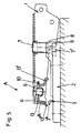
- FIG. 1 shows a longitudinal section through the hinge arm and the base plate in the assembled position
- Fig. 2 shows a plan view of the base plate and the hinge arm mounted thereon partly in section
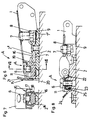
- Fig. 3 shows a cross section through the hinge arm and the base plate
- the Fig. 4 shows a side view and a top view of a retaining clip
- Fig. 5 shows a longitudinal section through a hinge arm in the position immediately preceding hooking on the base plate
- Fig. 6 shows a longitudinal section through a hinge arm and base plate in one 7 shows a section along the line VII-VII of FIG. 6,
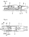
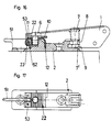
- FIGS. 8 to 11 each show a longitudinal section through the hinge arm and base plate in various embodiments of the invention
- FIG. 12 shows a plan view 11 partly in section on a hinge arm and base plate according to FIG. 13 shows a longitudinal section tt through the hinge arm and base plate in a further embodiment of the invention
- FIG. 14 shows a top view of the hinge arm and base plate according to FIG. 13, partly in section
- FIGS. 15 and 16 each show a longitudinal section through the hinge arm and base plate in two further embodiments of the Invention
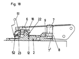
- Fig. 17 shows a plan view of a base plate according to Fig. 16
- Fig. 18 shows the same view as Fig. 16 in the release position of the hinge arm
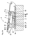
- Fig. 19 shows a longitudinal section through a hinge in the release position
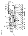
- the 20 shows a longitudinal section with the hinge arm anchored
- FIG. 21 shows the detail of the vein in FIG. 19, FIG.
- FIG. 22 shows a plan view of the hinge arm and base plate, partly in section
- FIG. 23 shows the section along the line A-wire Fig. 20 and the view X of Fig. 20
- Fig. 24 shows a longitudinal section through a hinge arm and a base plate in the position during hanging of the hinge arm in a further embodiment of the invention
- FIG. 25 shows in the same embodiment a longitudinal section through the hinge arm and the base plate with the hinge arm mounted
- FIG. 26 shows in this embodiment a longitudinal section through the hinge arm and the base plate when the intermediate piece is released .
- a resilient retaining clip 3 is inserted into the base plate 2.
- the holding clip 3 has a double web 3 'which bears on the pressure surfaces 2' of the base plate 2 distributed in a triangle and is thus pressed together.
- the hold of the retaining clip 3 in the base plate 2 is therefore relatively strong.
- the hinge arm 1 is at the front, i.e. provided at its end facing the articulated lever in a conventional manner with a joint adjusting screw 7 which is supported in a nut thread in the hinge arm 1 and is held with its head 7 'behind projections 8 of the base plate 2.
- the joint adjustment screw 7 can be tilted in the recess 9 which delimit the projections 8.
- the hinge arm 1 has a tab 10 punched out of its central web, in which there is a longitudinal slot 11 which is open to the rear and through which a clamping screw 6 projects.
- a holding clamp 13 is held by the clamping screw 6.
- This retaining clip 13 has a web 13 'which engages with its edge in a groove 12 in the base plate 2. The groove 12 and the edge of the web 13 'are aligned parallel to the axis of rotation of the hinge.
- the holding clip 13 Opposite the web 13 ', i.e. facing the rear end of the hinge arm 1, the holding clip 13 has a web 13 ", which is provided with a slot 14. The web 3" of the retaining clip 3 projects into the slot 14 in the installed position.
- the hinge arm 1 with the joint adjustment screw 7 is inserted into the recess 9 and then tilted in the direction of arrow A around the head 7 'of the joint adjustment screw 7 as a pivot bearing, as a result of which the retaining clip 13 is pressed onto the holding clip 3.
- the web 3 "of the clip 3 engages in the slot 14 of the web 13" of the holding clip 3 and, as already mentioned, the free edge of the web 13 'of the holding clip 13 projects into the groove 12 of the base plate 2.
- the hinge arm 1 is thus securely anchored on the base plate 2. If an adjustment is to be made in the direction of the furniture door, it is sufficient to turn the joint adjustment screw 7 in a conventional manner.
- the hinge arm 1 can adapt to any angular position due to the flexibility of the tab 1.
- the clamping screw 6 is loosened, whereupon the hinge arm 1 can be moved over the length of the elongated hole 11 or over the depth of the recess 9. After the setting, the clamping screw 6 is tightened again.
- the hinge arm is provided with a joint adjustment screw 7, the head 7 'of which projects into a recess 9 which is delimited by projections 8.
- the hinge arm 1 is in turn provided at its rear end with a slot 11 which is open to the rear.
- the base plate 2 has lateral grooves 16 in the rear area, which run out towards the front and towards the top surface 2 "of the base plate 2. Above the lateral grooves 16, the base plate 2 is provided with inclined surfaces 17 which diverge from the mounting plane 2" 'of the base plate 2 .
- the holding clip 15 has holding brackets 18 on the side, which snap into the grooves 16 of the base plate 2 when the hinge arm 1 is mounted. Furthermore, the holding clip 15 is provided with a resilient web 19 which, when the hinge arm 1 is mounted, lies against the top surface 2 ′′ of the base plate 2 and presses on it.
- the holding clip 15 also has a stop tab 20 which bears on the rear end face of the base plate 2. Above the stop tab 20, a grip part 21 is formed on the holding clip 15 or punched out of the holding clip 15. As in the previously described exemplary embodiment, the holding clip 15 is fastened to the hinge arm 1 by means of a clamping screw 6.
- the hinge arm 1 To mount the hinge arm 1, it is anchored to the base plate 2 by means of the joint adjusting screw 7, which is inserted into the recess 9, as in the previously described exemplary embodiment, and then rotated in the direction of the arrow A.
- the bracket 18 slide laterally over the inclined surfaces 17 and snap into the lateral grooves 16 of the base plate 2. Because the resilient web 19 presses on the base plate 2, the hinge arm 1 is fixed without play.
- the adjustment of the hinge arm 1 in the direction of the furniture door and the depth of the furniture is carried out, as in the embodiment described above, by turning the joint adjustment screw 7 or by opening the clamping screw 6 and moving the hinge arm 1.
- the hinge arm 1 If the hinge arm 1 is to be lifted off the base plate 2, either the clamping screw 6 can be loosened, whereupon the hinge arm 1 is pulled out, or the grip part 21 is pressed forward, whereby the stop tab 20 is lifted off the end face of the base plate 2. Then the hinge arm 1 can be pulled obliquely upwards and forwards out of the base plate 2 along the grooves 16.
- the hinge arm 1 is also mounted on the base plate 2 by first hanging the hinge arm 1 with the joint adjusting screw 7 into the base plate 2, then turning it in the direction of the arrow A and pressing it onto the base plate 2.
- a holding clamp 22 is held by the clamping screw 6, which in turn protrudes through a slot 11 of the hinge arm 1 which is open to the rear, which engages behind a projection 23 of the base plate 2 which projects to the rear and, when the hinge arm 1 is mounted, behind it Tab 23 hooks.
- a grip part 24 is formed on the holding clip 22, by means of which the bracket 25 of the holding clip 22 can be pressed away from the projection 23 in order to detach the hinge arm 1 from the base plate 2.
- the hinge arm 1 is provided with a holding clip 26, and a holding clip 27 is fastened on the base plate 2.
- the retaining clip 26 is pressed onto the retaining clip 27, engages behind a clip 27 'of a clip 27' of the retaining clip 27 and, on the other hand, presses with a clip 26 "onto a clip 27" of the clip 27 achieved firm hold of the hinge arm 1 on the base plate 2.
- the holding clip 26 is provided with a grip part 28, which is formed by a punched-out tab. With the handle part 28, the web 26 'can be lifted from the web 27' of the retaining clip 27 and the hinge arm 1 can be moved freely with respect to the base plate 2.
- the holding clip 26 is attached to the hinge arm 1 by means of an eccentric 29. By turning the eccentric 29, the hinge arm 1 is adjusted in the depth of the furniture.
- the retaining clip 27 is held by the screw 6.
- a holding clamp 30 is fastened on the base plate 2 by means of the clamping screw 6.
- the hinge arm 1 has recesses 31, 32 and webs 33 which protrude from side web to side web of the hinge arm 1 which is essentially designed with a U-profile.
- the holding clip 30 has sections 34, 35 which project upwards, the section 35 being directed obliquely to the hinge arm 1.
- the hinge arm 1 When the hinge arm 1 is assembled, it is in turn pressed onto the holding bracket 30 around the pivot bearing formed by the joint adjusting screw 7 and engages with its webs 33 behind the sections 34, 35 of the holding bracket 30.
- the retaining clip 30 is provided with a longitudinal slot 36 so that the adjustment of the hinge arm 1 in the direction of the depth of the furniture can be done in a conventional manner by loosening the clamping screw 6, whereupon the hinge arm 1 over the length of the longitudinal slot 36 or the depth of the Recess 9 can be moved.
- the holding clamp 37 is in turn fastened on the base plate 2 by means of the clamping screw 6.
- the holding clip 37 is provided with an open slot 38 and thus has two legs 39.
- knobs 40 On the outside of the leg 39 are knobs 40, which engage in recesses 41 of the hinge arm 1 when the hinge arm 1 is mounted.
- the recesses 41 are, for example, rectangular holes.
- the hinge arm 1 has webs 42 which are encompassed by the knobs 40 when the hinge arm 1 has been pivoted onto the base plate 2.
- the retaining clip 37 is resilient so that the legs 39 can be pressed together, whereby the webs 42 are released. The hinge arm 1 can then be pulled off the base plate 2. The adjustment in the depth of the furniture is possible through the slot 38.
- the holding clip 43 is designed as a slide which is guided in guides 44 of the base plate 2.
- the slide 43 is acted upon by a helical spring 45, which is located in a housing of the base plate 2.
- a pin 46 which has an annular groove 47, is attached to the hinge arm 1 by means of the clamping screw 6.
- the clamping screw 6 in turn protrudes through a slot 11 which is open to the rear in the hinge arm 1.
- the holding clip 43 formed by the slide has a keyhole 48 through which the pin 46 protrudes when the hinge arm 1 is mounted. At the rear end, the holding clip 43 is provided with a handle 49.
- the holding clip 43 also has a further longitudinal slot 50 through which a fastening screw for the base plate 2 protrudes.
- the holding clip 43 When the hinge arm 1 is pivoted onto the base plate 2, the holding clip 43 is either pushed back manually against the spring 45 so that the pin 46 can be inserted through the keyhole 48, or the pin 46 has a truncated cone-like configuration at its free end which forms the holding clip 43 pushes back by itself. If the pin 46 is in the position shown in FIG. 13, the spring 45 can insert the retaining clip 43 with the edges of the keyhole 48 into the annular groove 47 of the pin 46, whereupon the hinge arm 1 is held firmly and securely on the base plate 2.
- the adjustment of the hinge arm 1 in the The direction of the furniture door or in the direction of the depth of the furniture is the same as in the previously described exemplary embodiments.
- the holding clip 43 is pressed forward over the handle part 49, whereupon the pin 46 is pivoted out of the keyhole opening 48.
- the clamping screw 6 it would also be possible to loosen the clamping screw 6 and pull out the hinge arm 1 between the clamping screw 6 and the pin 46.
- the holding clip 22 hooks into the projection 23 of the base plate 2.
- the holding clip 22 engages behind the projection 23 on the back of the base plate 2 and projects into a groove 12.
- a pawl 51 is rotatably mounted on an axis 53.
- the pawl 51 is provided with a stop 52.
- the hinge arm 1 is mounted on the base plate 2 as in the previously described embodiment, i.e. hooked into the base plate 2 with the joint adjustment screw 7 and then pivoted so that the retaining clip 22 snaps into the projection 23.
- the pawl 51 As shown in FIG. 18, is pressed upward, as a result of which the leg of the holding clip 22 is pressed off by the projection 23.
- the hinge arm 1 is thus free.
- the parts of the hinge essential to the invention are the hinge arm 1, the base plate 2 and the intermediate piece 4 with the tilting part 5.
- the hinge arm 1 is fastened to the intermediate piece 4 by means of the joint adjustment screw 7, which is supported in a nut thread in the hinge arm 1 and by means of a clamping screw 6, which also serves for the depth adjustment.
- the clamping screw 6 protrudes through a longitudinal slot in the hinge arm 1 and likewise the joint adjusting screw 7 is held with its head 7 'in a recess in the intermediate piece 4 which is designed as an open longitudinal slot 9.
- the hinge arm 1 can be moved along the length of the longitudinal slot and thus adjusted in the depth of the furniture.
- the adjustment in the direction of the furniture door is carried out in a conventional manner by turning the joint adjustment screw 7.
- Both the base plate 2 and the intermediate piece 4 are designed with a U-profile and their legs 2 ', 4' project into one another when the hinge arm 1 is placed on the base plate 2.
- the intermediate piece 4 is provided with a continuous pin 63, which serves as a holding projection of the intermediate piece 4.
- the webs 2 'of the base plate 2 have notches 53 into which the pin 63 can be inserted, so that it is held behind the edge projections of the webs 2'.
- the pin 63 and the notches 53 fulfill the task of the joint adjustment screw 7 and the recess 9 of the previously described exemplary embodiments.
- the base plate 2 is also provided with notches 54.
- the tilting part 5 is supported by means of a pin 64.
- the resilient holding projection 57 is formed on the tilting part 5, which in turn is formed by a pin.
- the tilting part 5 is acted upon by a leg spring 64, which is wound around the bearing pin of the tilting part 5 and is supported with one leg 64 'on the intermediate piece 4 and with the other leg 64 "on the pin 57.
- a cover cap 65 can be provided on the hinge arm 1, which covers the clamping screw 6 and the joint adjustment screw 7 after adjustment.
- a handle part 5 ' is formed on the tilting part 5. If the hinge arm 1 is to be detached from the base plate 2, it is sufficient to press this grip part 5 ', whereupon the pin 57 disengages from the notch 54 and the hinge arm 1 with the intermediate piece 4 can be lifted off the base plate 2.
- FIGS. 24 to 26 The exemplary embodiment according to FIGS. 24 to 26 is described below.
- the hinge arm 1 is in turn attached to the intermediate piece 4 by means of a joint adjusting screw 7 which is supported in a nut thread in the hinge arm 1 and by means of a clamping screw 6 which also serves for the depth adjustment.
- the clamping screw 6 protrudes through a longitudinal slot in the hinge arm 1 and likewise the joint adjustment screw 7 is held with its head 7 ′ in a longitudinal slot in the intermediate piece 4.
- the longitudinal slot forms the recess 9.
- Both the hinge arm 1 and the intermediate piece 4 are designed with a U-profile.
- the intermediate piece 4 is provided with a continuous pin 63, which serves as a holding projection of the intermediate piece 4.
- the base plate 2 has a notch 53 in the front, into which the pin 63 can be suspended, so that it is held on the base plate 2.
- the base plate 2 is also provided with a notch 54.
- the rocker arm 5 is supported at the rear end of the intermediate piece 4.
- the hook-like projection 57 is formed on the rocker arm 5.
- the rocker arm 5 is acted upon by a helical spring 58 which is mounted in a recess in the rocker arm 5 and is supported at one end on the hinge arm 1.
- the clamping screw 6 for the depth adjustment has a centering projection 55 which projects into a corresponding opening 56 in the base plate 2.
- the centering projection 55 is a cone and the opening 56 is funnel-shaped. In this way, the hinge arm 1 is immediately correctly positioned.
- the distances between the pin 63 and the centering lug 55 on the one hand and the notch 53 and the opening 56 on the other hand are, as already mentioned, chosen so that a slight tensioning occurs when the intermediate piece 4 is pressed on. As a result, the intermediate piece 4 is held on the base plate 2 without play.
- a handle part 5 ' is formed on the tilting part 5. If the hinge arm 1 is to be detached from the base plate 2, it suffices to raise this grip part 5 ', whereupon the projection 57 disengages from the notch 54 and the hinge arm 1 with the intermediate piece 4 can be lifted off the base plate 2.
- the nose 62 presses on the base plate 2 and acts like a lever. In this way, it is possible to easily loosen the centering projection 55 despite the tension.
- the clamping screw 6 is loosened and the upper part 2 'of the base plate 2 is displaced at the lower part 2 ".
- the guide 59 prevents the hinge arm 1 from tilting. After the height adjustment has taken place, the clamping screw 6 is tightened.
- top and bottom used in the course of the description refer to the figures in the drawing and not to the position of the hinge mounted on the furniture.
- hinge arm is hooked directly or indirectly onto the base plate at one end and is then rotated about this pivot bearing, whereupon the other end snaps into a latch-like locking.
- the hinge arm is hooked in at the end which faces the joint or the joint levers.
Landscapes
- Engineering & Computer Science (AREA)
- Mechanical Engineering (AREA)
- Hinges (AREA)
- Vehicle Step Arrangements And Article Storage (AREA)
- Closing And Opening Devices For Wings, And Checks For Wings (AREA)
- Superstructure Of Vehicle (AREA)
Applications Claiming Priority (8)
| Application Number | Priority Date | Filing Date | Title |
|---|---|---|---|
| AT3337/84 | 1984-10-19 | ||
| AT333684A AT382673B (de) | 1984-10-19 | 1984-10-19 | Scharnier |
| AT3336/84 | 1984-10-19 | ||
| AT333784A AT391910B (de) | 1984-10-19 | 1984-10-19 | Scharnier |
| AT0139385A AT384270B (de) | 1985-05-09 | 1985-05-09 | Scharnier |
| AT1393/85 | 1985-05-09 | ||
| AT0240485A AT382674B (de) | 1985-08-19 | 1985-08-19 | Scharnier mit verstelleinrichtungen |
| AT2404/85 | 1985-08-19 |
Related Child Applications (1)
| Application Number | Title | Priority Date | Filing Date |
|---|---|---|---|
| EP89116698.5 Division-Into | 1985-10-03 |
Publications (3)
| Publication Number | Publication Date |
|---|---|
| EP0200744A1 EP0200744A1 (de) | 1986-11-12 |
| EP0200744B1 EP0200744B1 (de) | 1990-04-18 |
| EP0200744B2 true EP0200744B2 (de) | 1993-09-29 |
Family
ID=27421527
Family Applications (3)
| Application Number | Title | Priority Date | Filing Date |
|---|---|---|---|
| EP85905043A Expired - Lifetime EP0200744B2 (de) | 1984-10-19 | 1985-10-03 | Scharnier |
| EP89116698A Expired - Lifetime EP0349018B1 (de) | 1984-10-19 | 1985-10-03 | Scharnier |
| EP19930100005 Ceased EP0538240A3 (en) | 1984-10-19 | 1985-10-03 | Hinge |
Family Applications After (2)
| Application Number | Title | Priority Date | Filing Date |
|---|---|---|---|
| EP89116698A Expired - Lifetime EP0349018B1 (de) | 1984-10-19 | 1985-10-03 | Scharnier |
| EP19930100005 Ceased EP0538240A3 (en) | 1984-10-19 | 1985-10-03 | Hinge |
Country Status (11)
| Country | Link |
|---|---|
| US (4) | US4800622A (it) |
| EP (3) | EP0200744B2 (it) |
| JP (1) | JP2722163B2 (it) |
| KR (1) | KR940003074B1 (it) |
| AT (2) | ATE52127T1 (it) |
| CA (2) | CA1270609A (it) |
| DE (3) | DE3577222D1 (it) |
| ES (1) | ES296221Y (it) |
| HK (1) | HK61891A (it) |
| IT (1) | IT206607Z2 (it) |
| WO (1) | WO1986002402A1 (it) |
Families Citing this family (46)
| Publication number | Priority date | Publication date | Assignee | Title |
|---|---|---|---|---|
| US5056190A (en) * | 1984-10-19 | 1991-10-15 | Julius Blum Gesellschaft M.B.H. | Hinge with hinge arm releasably connected to mounting plate |
| DE3577222D1 (de) | 1984-10-19 | 1990-05-23 | Blum Gmbh Julius | Scharnier. |
| DE3679963D1 (de) * | 1985-12-10 | 1991-08-01 | Blum Gmbh Julius | Scharnier. |
| AU584782B2 (en) * | 1986-02-10 | 1989-06-01 | Julius Blum Gesellschaft M.B.H. | Hinge |
| US4760623A (en) * | 1986-03-20 | 1988-08-02 | Kabushiki Kaisha Murakoshi Seiko | Hinge |
| AT383852B (de) * | 1986-04-10 | 1987-09-10 | Blum Gmbh Julius | Scharnier |
| ES2032145T3 (es) * | 1986-04-29 | 1993-01-01 | Julius Blum Gesellschaft M.B.H. | Charnela |
| JP2553121B2 (ja) * | 1986-06-14 | 1996-11-13 | パウル ヘテイツヒ ゲゼルシヤフト ミツト ベシユレンクテル ハフツング ウント コンパニイ | 家具蝶番 |
| DE3775652D1 (de) * | 1986-08-08 | 1992-02-13 | Salice Arturo Spa | Scharnierarm fuer ein moebelscharnier o.dgl. |
| DE3639276A1 (de) * | 1986-11-17 | 1988-05-26 | Grass Alfred Metallwaren | Moebelscharnier mit schnellverschluss |
| DE3640012A1 (de) * | 1986-11-24 | 1988-06-01 | Salice Arturo Spa | Zweiteiliger verbindungsbeschlag |
| DE3718730C2 (de) * | 1987-06-04 | 1996-11-28 | Grass Alfred Metallwaren | Beschlag für einen Schrank mit hochschwenkbarer Tür |
| AT398800B (de) * | 1987-08-18 | 1995-01-25 | Blum Gmbh Julius | Scharnier |
| AT391344B (de) * | 1987-08-31 | 1990-09-25 | Blum Gmbh Julius | Scharnier |
| DE3744906C2 (de) * | 1987-10-06 | 1994-11-03 | Grass Ag | Möbelscharnier mit Rastmechanik |
| JPH063088B2 (ja) * | 1988-05-16 | 1994-01-12 | スガツネ工業株式会社 | ヒンジ |
| DE3820338A1 (de) * | 1988-06-15 | 1989-12-21 | Lautenschlaeger Kg Karl | Moebelscharnier |
| EP0369532B1 (en) * | 1988-11-16 | 1994-04-13 | Franco Ferrari | Quick coupling door hinge |
| ES1009089Y (es) * | 1989-02-17 | 1989-12-16 | Blanco Eguiluz M. Begona | Dispositivo de enganche rapido para bisagras de muebles. |
| AU629378B2 (en) * | 1989-08-11 | 1992-10-01 | Sugatsune Industrial Co., Ltd | Device for detachably connecting a pair of members |
| DE9005706U1 (de) * | 1990-05-19 | 1990-07-26 | Julius Blum Ges.m.b.H., Höchst | Scharnier |
| DE9109861U1 (de) * | 1991-06-26 | 1992-11-19 | Grass AG, Höchst, Vorarlberg | Möbelverbinder zur Verbindung von Möbelteilen |
| AT404378B (de) * | 1995-06-20 | 1998-11-25 | Blum Gmbh Julius | Scharnier |
| AT1214U1 (de) * | 1995-12-18 | 1996-12-27 | Blum Gmbh Julius | Scharnier |
| ATE313679T1 (de) * | 1996-02-14 | 2006-01-15 | Blum Gmbh Julius | Scharnier |
| TW363106B (en) * | 1997-02-25 | 1999-07-01 | Sugatsune Kogyo | Twisting chain |
| DE19707741C2 (de) * | 1997-02-27 | 2003-07-03 | Grass Gmbh Hoechst | Möbelscharnier |
| AT405433B (de) * | 1997-06-25 | 1999-08-25 | Blum Gmbh Julius | Scharnier |
| WO1999051843A1 (de) * | 1998-04-01 | 1999-10-14 | MEPLA-WERKE LAUTENSCHLäGER GMBH & CO. KG | Montageplatte für möbelscharniere |
| AT407277B (de) | 1998-08-11 | 2001-02-26 | Blum Gmbh Julius | Scharnier |
| AT406497B (de) * | 1998-08-17 | 2000-05-25 | Blum Gmbh Julius | Scharnier |
| EP0982455B1 (de) | 1998-08-25 | 2005-01-26 | Julius Blum GmbH | Möbelscharnier |
| DE29822770U1 (de) | 1998-12-21 | 1999-02-18 | Arturo Salice S.P.A., Novedrate, Como | Scharnier |
| AT409288B (de) * | 2000-02-28 | 2002-07-25 | Blum Gmbh Julius | Möbelscharnier |
| DE20009317U1 (de) * | 2000-05-24 | 2000-08-17 | Arturo Salice S.P.A., Novedrate, Como | Befestigungsplatte zur Befestigung eines Scharnierarmes eines Möbelscharniers |
| AT6963U1 (de) * | 2003-02-21 | 2004-06-25 | Blum Gmbh Julius | Scharnier |
| US8839488B2 (en) * | 2006-06-20 | 2014-09-23 | Hardware Resources, Inc. | Adjustable hinge |
| DE102007026211B4 (de) * | 2007-05-03 | 2013-06-27 | Liberty Hardware Mfg. Corp. | Möbelscharnier mit einer Dämpfungseinrichtung |
| SI23057A (sl) * | 2009-05-13 | 2010-11-30 | LAMA@d@d@@Dekani | Naprava za pritrditev predmeta na pohištveno stranico prednostno na stranico korpusa |
| WO2015068714A1 (ja) * | 2013-11-11 | 2015-05-14 | スガツネ工業株式会社 | ヒンジ装置及びヒンジ装置基部 |
| DE102017112767A1 (de) * | 2017-06-09 | 2018-12-13 | Hettich-Oni Gmbh & Co. Kg | Scharnier |
| DE202018102084U1 (de) * | 2018-04-17 | 2019-07-29 | Grass Gmbh | Vorrichtung zur Bewegung eines an einem Möbelkorpus eines Möbels aufgenommenen Möbelteils |
| CN110206427A (zh) * | 2019-05-25 | 2019-09-06 | 广东联迅精密制造有限公司 | 一种缓冲铰链快速拆装结构 |
| CN111155857A (zh) * | 2020-01-15 | 2020-05-15 | 广东东泰五金精密制造有限公司 | 一种家具铰链的无间隙调节结构 |
| AT523441B1 (de) * | 2020-01-17 | 2023-05-15 | Blum Gmbh Julius | Scharnieranordnung |
| AT525067B1 (de) * | 2021-11-26 | 2022-12-15 | Blum Gmbh Julius | Beschlag zur bewegbaren Lagerung eines Schwenkelementes relativ zu einem stationären Träger |
Citations (11)
| Publication number | Priority date | Publication date | Assignee | Title |
|---|---|---|---|---|
| DE2406438A1 (de) † | 1974-02-11 | 1975-08-21 | Praemeta | Scharnierband fuer aufliegende tuerfluegel, insbesondere moebelscharnier |
| DE2513089A1 (de) † | 1974-04-01 | 1975-10-09 | Blum Gmbh Julius | Scharnierarm |
| US3977041A (en) † | 1973-12-31 | 1976-08-31 | Blum Gesellschaft M.B.H. | Hinge device |
| DE2815816A1 (de) † | 1978-04-12 | 1979-10-18 | Salice Gmbh | Verstellbarer scharnierarm |
| US4176422A (en) † | 1977-05-11 | 1979-12-04 | Julius Blum Gesellschaft M.B.H. | Furniture hinge |
| AT360856B (de) † | 1977-02-28 | 1980-02-10 | Blum Gmbh Julius | Halte- bzw. verriegelungseinrichtung fuer ein zwischenstueck eines scharnieres mit verstelleinrichtungen |
| US4304028A (en) † | 1978-11-20 | 1981-12-08 | Julius Blum Gesellschaft M.B.H. | Hinge |
| DE3026796A1 (de) † | 1980-07-15 | 1982-01-28 | Deutsche Salice Gmbh, 7141 Freiberg | Scharnierarm mit befestigungsplatte |
| DE3305272A1 (de) † | 1982-02-16 | 1983-08-25 | Industria Técnica de la Bisagra, S.L., Aya, Guipúzcoa | Befestigungsplatte fuer scharnierarm |
| US4412364A (en) † | 1980-03-18 | 1983-11-01 | Fernando Orea Mateo | Process for the normalized manufacture of shoes |
| DE3445885A1 (de) † | 1983-12-30 | 1985-07-11 | Julius Blum GmbH, Höchst | Scharnier |
Family Cites Families (16)
| Publication number | Priority date | Publication date | Assignee | Title |
|---|---|---|---|---|
| US3969787A (en) * | 1973-12-24 | 1976-07-20 | Blum Gesellschaft M.B.H. | Hinge device |
| DE2460127C3 (de) * | 1974-12-19 | 1981-11-05 | Karl Lautenschläger KG, Möbelbeschlagfabrik, 6107 Reinheim | Möbelscharnier |
| CH608556A5 (it) * | 1975-04-07 | 1979-01-15 | Blum Gmbh Julius | |
| DE2719890C2 (de) * | 1976-05-06 | 1986-03-20 | Paul Hettich & Co, 4983 Kirchlengern | Scharnier |
| DE2657628A1 (de) * | 1976-12-20 | 1978-06-22 | Heinze Richard | Moebelscharnier |
| AT371205B (de) * | 1977-02-28 | 1983-06-10 | Blum Gmbh Julius | Halte- bzw. verriegelungseinrichtung fuer ein zwischenstueck eines scharnieres |
| DE3161939D1 (en) * | 1980-07-15 | 1984-02-23 | Salice Arturo Spa | Hinge arm with mounting plate |
| DE3039328C2 (de) * | 1980-10-17 | 1986-02-27 | Arturo Salice S.P.A., Novedrate, Como | Scharnier mit einem Scharnierarm und einer Befestigungsplatte |
| DE3119571A1 (de) * | 1981-05-16 | 1982-12-16 | Karl Lautenschläger KG, Möbelbeschlagfabrik, 6107 Reinheim | "moebelscharnier" |
| DE3241284A1 (de) * | 1982-11-09 | 1984-05-10 | Paul Hettich & Co, 4983 Kirchlengern | Moebelscharnier |
| DE3302312A1 (de) * | 1983-01-25 | 1984-07-26 | Karl Lautenschläger KG, Möbelbeschlagfabrik, 6107 Reinheim | Moebelscharnier |
| JPS6078667U (ja) * | 1983-11-04 | 1985-06-01 | アップリカ葛西株式会社 | 手押車のハンドル高さ調整機構 |
| DE3577222D1 (de) | 1984-10-19 | 1990-05-23 | Blum Gmbh Julius | Scharnier. |
| DE3679963D1 (de) * | 1985-12-10 | 1991-08-01 | Blum Gmbh Julius | Scharnier. |
| AT386862B (de) * | 1985-12-10 | 1988-10-25 | Blum Gmbh Julius | Scharnier |
| DE3624237A1 (de) * | 1986-03-06 | 1987-09-10 | Grass Alfred Metallwaren | Scharnierband mit leicht loesbarer befestigung des moebelseitigen abdeckbuegels am moebelteil |
-
1985
- 1985-10-03 DE DE8585905043T patent/DE3577222D1/de not_active Expired - Fee Related
- 1985-10-03 US US06/878,868 patent/US4800622A/en not_active Expired - Lifetime
- 1985-10-03 EP EP85905043A patent/EP0200744B2/de not_active Expired - Lifetime
- 1985-10-03 WO PCT/AT1985/000037 patent/WO1986002402A1/de not_active Ceased
- 1985-10-03 DE DE8590141U patent/DE8590141U1/de not_active Expired
- 1985-10-03 AT AT85905043T patent/ATE52127T1/de not_active IP Right Cessation
- 1985-10-03 DE DE89116698T patent/DE3587560D1/de not_active Expired - Lifetime
- 1985-10-03 EP EP89116698A patent/EP0349018B1/de not_active Expired - Lifetime
- 1985-10-03 EP EP19930100005 patent/EP0538240A3/de not_active Ceased
- 1985-10-03 AT AT89116698T patent/ATE93923T1/de not_active IP Right Cessation
- 1985-10-10 IT IT8506737U patent/IT206607Z2/it active
- 1985-10-10 CA CA000492669A patent/CA1270609A/en not_active Expired - Fee Related
- 1985-10-18 ES ES1985296221U patent/ES296221Y/es not_active Expired
-
1986
- 1986-05-27 KR KR8670305A patent/KR940003074B1/ko not_active Expired - Fee Related
-
1988
- 1988-09-19 US US07/246,073 patent/US4888853A/en not_active Expired - Lifetime
- 1988-09-19 US US07/246,074 patent/US4882808A/en not_active Expired - Fee Related
- 1988-09-19 US US07/246,072 patent/US4908907A/en not_active Expired - Fee Related
-
1989
- 1989-09-29 CA CA000615494A patent/CA1277813C/en not_active Expired - Fee Related
-
1991
- 1991-08-08 HK HK618/91A patent/HK61891A/xx not_active IP Right Cessation
-
1993
- 1993-05-27 JP JP5146769A patent/JP2722163B2/ja not_active Expired - Fee Related
Patent Citations (11)
| Publication number | Priority date | Publication date | Assignee | Title |
|---|---|---|---|---|
| US3977041A (en) † | 1973-12-31 | 1976-08-31 | Blum Gesellschaft M.B.H. | Hinge device |
| DE2406438A1 (de) † | 1974-02-11 | 1975-08-21 | Praemeta | Scharnierband fuer aufliegende tuerfluegel, insbesondere moebelscharnier |
| DE2513089A1 (de) † | 1974-04-01 | 1975-10-09 | Blum Gmbh Julius | Scharnierarm |
| AT360856B (de) † | 1977-02-28 | 1980-02-10 | Blum Gmbh Julius | Halte- bzw. verriegelungseinrichtung fuer ein zwischenstueck eines scharnieres mit verstelleinrichtungen |
| US4176422A (en) † | 1977-05-11 | 1979-12-04 | Julius Blum Gesellschaft M.B.H. | Furniture hinge |
| DE2815816A1 (de) † | 1978-04-12 | 1979-10-18 | Salice Gmbh | Verstellbarer scharnierarm |
| US4304028A (en) † | 1978-11-20 | 1981-12-08 | Julius Blum Gesellschaft M.B.H. | Hinge |
| US4412364A (en) † | 1980-03-18 | 1983-11-01 | Fernando Orea Mateo | Process for the normalized manufacture of shoes |
| DE3026796A1 (de) † | 1980-07-15 | 1982-01-28 | Deutsche Salice Gmbh, 7141 Freiberg | Scharnierarm mit befestigungsplatte |
| DE3305272A1 (de) † | 1982-02-16 | 1983-08-25 | Industria Técnica de la Bisagra, S.L., Aya, Guipúzcoa | Befestigungsplatte fuer scharnierarm |
| DE3445885A1 (de) † | 1983-12-30 | 1985-07-11 | Julius Blum GmbH, Höchst | Scharnier |
Also Published As
| Publication number | Publication date |
|---|---|
| ES296221Y (es) | 1988-02-16 |
| CA1277813C (en) | 1990-12-18 |
| US4882808A (en) | 1989-11-28 |
| US4908907A (en) | 1990-03-20 |
| ATE52127T1 (de) | 1990-05-15 |
| EP0200744B1 (de) | 1990-04-18 |
| US4800622A (en) | 1989-01-31 |
| EP0349018A2 (de) | 1990-01-03 |
| EP0538240A2 (de) | 1993-04-21 |
| KR880700146A (ko) | 1988-02-20 |
| DE3577222D1 (de) | 1990-05-23 |
| ATE93923T1 (de) | 1993-09-15 |
| EP0349018A3 (en) | 1990-07-04 |
| DE3587560D1 (de) | 1993-10-07 |
| ES296221U (es) | 1987-08-01 |
| IT206607Z2 (it) | 1987-08-10 |
| HK61891A (en) | 1991-08-16 |
| KR940003074B1 (en) | 1994-04-13 |
| EP0349018B1 (de) | 1993-09-01 |
| WO1986002402A1 (fr) | 1986-04-24 |
| IT8506737V0 (it) | 1985-10-10 |
| EP0200744A1 (de) | 1986-11-12 |
| CA1270609A (en) | 1990-06-26 |
| DE8590141U1 (de) | 1986-07-31 |
| JP2722163B2 (ja) | 1998-03-04 |
| EP0538240A3 (en) | 1993-06-02 |
| US4888853A (en) | 1989-12-26 |
| JPH06158930A (ja) | 1994-06-07 |
Similar Documents
| Publication | Publication Date | Title |
|---|---|---|
| EP0200744B2 (de) | Scharnier | |
| DE19920137C2 (de) | Montageplatte für Möbelscharniere | |
| EP0698357B1 (de) | Möbelbeschlag, insbesondere Verbindungsbeschlag | |
| EP0267477B1 (de) | Befestigungsvorrichtung für einstellbare Frontblenden von Schubladen | |
| AT391162B (de) | Scharnier | |
| EP2207456B1 (de) | Blendenhalter zur befestigung einer frontblende an einer schubladenzarge | |
| DE3535961C2 (it) | ||
| DE3119571C2 (it) | ||
| EP0664984A2 (de) | Differentialauszug für Schubladen | |
| EP0225609B1 (de) | Scharnier | |
| DE2806958C2 (de) | Scharnier | |
| DE2614446A1 (de) | Scharnier | |
| AT399195B (de) | Möbelscharnier mit einschnappmechanik | |
| DE4016664A1 (de) | Scharnier | |
| DE8632799U1 (de) | Scharnier | |
| DE2458566C2 (it) | ||
| DE2624453C2 (de) | Montageplatte für Möbelscharniere | |
| DE8611716U1 (de) | Scharnier mit Verstelleinrichtungen | |
| AT405433B (de) | Scharnier | |
| AT399261B (de) | Frontblendenhalterung für schubladen | |
| EP0392570B1 (de) | Scharnier | |
| AT391910B (de) | Scharnier | |
| AT396005B (de) | Befestigungselement mit einer duebelartigen buchse | |
| EP0086329A1 (de) | Verbindungsvorrichtung | |
| DE8632598U1 (de) | Scharnier |
Legal Events
| Date | Code | Title | Description |
|---|---|---|---|
| PUAI | Public reference made under article 153(3) epc to a published international application that has entered the european phase |
Free format text: ORIGINAL CODE: 0009012 |
|
| 17P | Request for examination filed |
Effective date: 19860606 |
|
| AK | Designated contracting states |
Kind code of ref document: A1 Designated state(s): AT DE FR GB IT SE |
|
| 17Q | First examination report despatched |
Effective date: 19871110 |
|
| GRAA | (expected) grant |
Free format text: ORIGINAL CODE: 0009210 |
|
| AK | Designated contracting states |
Kind code of ref document: B1 Designated state(s): AT DE FR GB IT SE |
|
| REF | Corresponds to: |
Ref document number: 52127 Country of ref document: AT Date of ref document: 19900515 Kind code of ref document: T |
|
| XX | Miscellaneous (additional remarks) |
Free format text: TEILANMELDUNG 89116698.5 EINGEREICHT AM 03/10/85. |
|
| GBT | Gb: translation of ep patent filed (gb section 77(6)(a)/1977) | ||
| REF | Corresponds to: |
Ref document number: 3577222 Country of ref document: DE Date of ref document: 19900523 |
|
| ITF | It: translation for a ep patent filed | ||
| ET | Fr: translation filed | ||
| PLBI | Opposition filed |
Free format text: ORIGINAL CODE: 0009260 |
|
| 26 | Opposition filed |
Opponent name: JUELICHER GMBH Effective date: 19910117 Opponent name: FIRMA GRASS AG Effective date: 19910116 |
|
| ITTA | It: last paid annual fee | ||
| PUAH | Patent maintained in amended form |
Free format text: ORIGINAL CODE: 0009272 |
|
| STAA | Information on the status of an ep patent application or granted ep patent |
Free format text: STATUS: PATENT MAINTAINED AS AMENDED |
|
| 27A | Patent maintained in amended form |
Effective date: 19930929 |
|
| AK | Designated contracting states |
Kind code of ref document: B2 Designated state(s): AT DE FR GB IT SE |
|
| ITF | It: translation for a ep patent filed | ||
| GBTA | Gb: translation of amended ep patent filed (gb section 77(6)(b)/1977) |
Effective date: 19931117 |
|
| ET3 | Fr: translation filed ** decision concerning opposition | ||
| EAL | Se: european patent in force in sweden |
Ref document number: 85905043.7 |
|
| REG | Reference to a national code |
Ref country code: GB Ref legal event code: IF02 |
|
| PGFP | Annual fee paid to national office [announced via postgrant information from national office to epo] |
Ref country code: GB Payment date: 20031001 Year of fee payment: 19 |
|
| PGFP | Annual fee paid to national office [announced via postgrant information from national office to epo] |
Ref country code: AT Payment date: 20031014 Year of fee payment: 19 |
|
| PGFP | Annual fee paid to national office [announced via postgrant information from national office to epo] |
Ref country code: SE Payment date: 20031017 Year of fee payment: 19 |
|
| PGFP | Annual fee paid to national office [announced via postgrant information from national office to epo] |
Ref country code: FR Payment date: 20031027 Year of fee payment: 19 |
|
| PGFP | Annual fee paid to national office [announced via postgrant information from national office to epo] |
Ref country code: DE Payment date: 20031223 Year of fee payment: 19 |
|
| PG25 | Lapsed in a contracting state [announced via postgrant information from national office to epo] |
Ref country code: GB Free format text: LAPSE BECAUSE OF NON-PAYMENT OF DUE FEES Effective date: 20041003 Ref country code: AT Free format text: LAPSE BECAUSE OF NON-PAYMENT OF DUE FEES Effective date: 20041003 |
|
| PG25 | Lapsed in a contracting state [announced via postgrant information from national office to epo] |
Ref country code: SE Free format text: LAPSE BECAUSE OF NON-PAYMENT OF DUE FEES Effective date: 20041004 |
|
| PG25 | Lapsed in a contracting state [announced via postgrant information from national office to epo] |
Ref country code: DE Free format text: LAPSE BECAUSE OF NON-PAYMENT OF DUE FEES Effective date: 20050503 |
|
| GBPC | Gb: european patent ceased through non-payment of renewal fee |
Effective date: 20041003 |
|
| EUG | Se: european patent has lapsed | ||
| PG25 | Lapsed in a contracting state [announced via postgrant information from national office to epo] |
Ref country code: FR Free format text: LAPSE BECAUSE OF NON-PAYMENT OF DUE FEES Effective date: 20050630 |
|
| REG | Reference to a national code |
Ref country code: FR Ref legal event code: ST |