EP0200744B2 - Hinge - Google Patents
Hinge Download PDFInfo
- Publication number
- EP0200744B2 EP0200744B2 EP85905043A EP85905043A EP0200744B2 EP 0200744 B2 EP0200744 B2 EP 0200744B2 EP 85905043 A EP85905043 A EP 85905043A EP 85905043 A EP85905043 A EP 85905043A EP 0200744 B2 EP0200744 B2 EP 0200744B2
- Authority
- EP
- European Patent Office
- Prior art keywords
- base plate
- hinge
- hinge arm
- arm
- holding
- Prior art date
- Legal status (The legal status is an assumption and is not a legal conclusion. Google has not performed a legal analysis and makes no representation as to the accuracy of the status listed.)
- Expired - Lifetime
Links
- 238000003825 pressing Methods 0.000 abstract description 2
- 238000004873 anchoring Methods 0.000 description 3
- 238000010276 construction Methods 0.000 description 2
- 230000015572 biosynthetic process Effects 0.000 description 1
- 210000003462 vein Anatomy 0.000 description 1
Images


Classifications
-
- E—FIXED CONSTRUCTIONS
- E05—LOCKS; KEYS; WINDOW OR DOOR FITTINGS; SAFES
- E05D—HINGES OR SUSPENSION DEVICES FOR DOORS, WINDOWS OR WINGS
- E05D7/00—Hinges or pivots of special construction
-
- E—FIXED CONSTRUCTIONS
- E05—LOCKS; KEYS; WINDOW OR DOOR FITTINGS; SAFES
- E05D—HINGES OR SUSPENSION DEVICES FOR DOORS, WINDOWS OR WINGS
- E05D7/00—Hinges or pivots of special construction
- E05D7/04—Hinges adjustable relative to the wing or the frame
- E05D7/0407—Hinges adjustable relative to the wing or the frame the hinges having two or more pins and being specially adapted for cabinets or furniture
-
- E—FIXED CONSTRUCTIONS
- E05—LOCKS; KEYS; WINDOW OR DOOR FITTINGS; SAFES
- E05D—HINGES OR SUSPENSION DEVICES FOR DOORS, WINDOWS OR WINGS
- E05D7/00—Hinges or pivots of special construction
- E05D7/12—Hinges or pivots of special construction to allow easy detachment of the hinge from the wing or the frame
- E05D7/123—Hinges or pivots of special construction to allow easy detachment of the hinge from the wing or the frame specially adapted for cabinets or furniture
- E05D7/125—Hinges or pivots of special construction to allow easy detachment of the hinge from the wing or the frame specially adapted for cabinets or furniture the hinge having two or more pins
-
- E—FIXED CONSTRUCTIONS
- E05—LOCKS; KEYS; WINDOW OR DOOR FITTINGS; SAFES
- E05D—HINGES OR SUSPENSION DEVICES FOR DOORS, WINDOWS OR WINGS
- E05D5/00—Construction of single parts, e.g. the parts for attachment
- E05D5/02—Parts for attachment, e.g. flaps
- E05D5/0276—Parts for attachment, e.g. flaps for attachment to cabinets or furniture, the hinge having two or more pins
-
- E—FIXED CONSTRUCTIONS
- E05—LOCKS; KEYS; WINDOW OR DOOR FITTINGS; SAFES
- E05Y—INDEXING SCHEME ASSOCIATED WITH SUBCLASSES E05D AND E05F, RELATING TO CONSTRUCTION ELEMENTS, ELECTRIC CONTROL, POWER SUPPLY, POWER SIGNAL OR TRANSMISSION, USER INTERFACES, MOUNTING OR COUPLING, DETAILS, ACCESSORIES, AUXILIARY OPERATIONS NOT OTHERWISE PROVIDED FOR, APPLICATION THEREOF
- E05Y2600/00—Mounting or coupling arrangements for elements provided for in this subclass
- E05Y2600/50—Mounting methods; Positioning
- E05Y2600/52—Toolless
- E05Y2600/53—Snapping
-
- E—FIXED CONSTRUCTIONS
- E05—LOCKS; KEYS; WINDOW OR DOOR FITTINGS; SAFES
- E05Y—INDEXING SCHEME ASSOCIATED WITH SUBCLASSES E05D AND E05F, RELATING TO CONSTRUCTION ELEMENTS, ELECTRIC CONTROL, POWER SUPPLY, POWER SIGNAL OR TRANSMISSION, USER INTERFACES, MOUNTING OR COUPLING, DETAILS, ACCESSORIES, AUXILIARY OPERATIONS NOT OTHERWISE PROVIDED FOR, APPLICATION THEREOF
- E05Y2900/00—Application of doors, windows, wings or fittings thereof
- E05Y2900/20—Application of doors, windows, wings or fittings thereof for furniture, e.g. cabinets
-
- Y—GENERAL TAGGING OF NEW TECHNOLOGICAL DEVELOPMENTS; GENERAL TAGGING OF CROSS-SECTIONAL TECHNOLOGIES SPANNING OVER SEVERAL SECTIONS OF THE IPC; TECHNICAL SUBJECTS COVERED BY FORMER USPC CROSS-REFERENCE ART COLLECTIONS [XRACs] AND DIGESTS
- Y10—TECHNICAL SUBJECTS COVERED BY FORMER USPC
- Y10S—TECHNICAL SUBJECTS COVERED BY FORMER USPC CROSS-REFERENCE ART COLLECTIONS [XRACs] AND DIGESTS
- Y10S16/00—Miscellaneous hardware, e.g. bushing, carpet fastener, caster, door closer, panel hanger, attachable or adjunct handle, hinge, window sash balance
- Y10S16/43—Hinge mounting bracket
Definitions
- the invention relates to a hinge with an adjustable hinge arm on a base plate, with a joint adjusting screw or the like. and an adjustment device acting in the depth of the piece of furniture, the hinge arm being indirectly held on the base plate at two bearing points offset along the length of the hinge arm by means of an intermediate piece by the intermediate piece being able to be positively hooked into the base plate at a first bearing point and through at a second bearing point a resilient locking connection is held.
- the hinge arm is fastened to the base plate by means of a clamping screw, this clamping screw generally protruding through an elongated hole, in order to make it possible to adjust the hinge arm in the depth of the furniture.
- DE-A-30 26 796 and 30 39 328 show hinges with a hinge arm and a fastening plate, in which, by inserting the hinge arm into a guide of the fastening plate and displacing it in the longitudinal direction, the two parts to be locked snap together.
- a similar anchoring of a hinge arm on a base plate is shown in DE-A-24 60 127.
- DE-A-32 41 284 shows a hinge in which the hinge arm can be inserted into lateral guides of a base plate and clamped on the base plate by means of an eccentric.
- DE-A-3 119 571 describes a hinge in which the hinge arm is connected to an intermediate piece by means of a clamping screw which also serves for the depth adjustment.
- the base plate is inserted into the furniture wall using thick dowel pins. Hooks of the intermediate piece protrude into the dowel pins, which are hollow.
- the intermediate piece is attached to the front of the base plate with a front hook and then tilted back.
- the rear hook of the intermediate piece engages on a resilient hook of the base plate, which is located in the rear dowel pin.
- the formation of the base plate is relatively complicated. The intermediate piece once anchored on the base plate is difficult to remove.
- DE-A-3 302 312 shows a hinge in which the hinge arm is pushed into the base plate at the front by means of the joint adjustment screw.
- the hinge arm is fixed by a clamping screw located at the rear end of the base plate, which also serves for depth adjustment and which projects through an elongated hole in the hinge arm that is open to the rear.
- the hinge arm During assembly, the hinge arm must be pushed with its rear end under the head of this clamping screw, which is screwed into the base plate.
- the hinge arm is therefore not, as in the construction according to DE-A-3 119 571, suspended in the base plate and then tilted to be automatically locked, but is pushed into the base plate from the front and is only held when the Clamping screw is tightened.
- the hinge arm anchorings described above have the advantage that the hinge arm can be fixed very quickly on the base plate when the furniture is being assembled, and that furthermore no tools are required for assembly. This advantage should not be underestimated, since the door leaf must be held when the hinge arms are attached. If, for example, the door leaf is held with one hand and the hinge arm to be put on with the other, then in many cases, if the hinge arm is locked by means of a clamping screw, a second person is required to tighten the clamping screw with a screwdriver.
- the object of the invention is to improve a hinge with a resilient locking lock, in which a depth adjustment of the hinge arm is possible, in that it is simple in construction and the hinge arm with the intermediate piece is easily placed on the base plate and released from it can be.
- the base plate should be attached to the furniture using screws or conventional dowels.
- a rocker arm is rotatably supported on an axis at the intermediate piece at the second bearing point, which has a hook-like projection which engages in a notch in the base plate, that the intermediate piece has a U-profile in cross section and at its first bearing point with a continuous pin is provided, which is supported on the two side webs of the intermediate piece and which serves as a holding projection of the intermediate piece and that the base plate has a notch at this first bearing point, into which the pin can be hung, the pin and the notch forming a pivot bearing, around which the intermediate piece with the hinge arm is rotatable and that the rocker arm, which is supported between the two side webs of the intermediate piece, by a spring is acted upon.
- An embodiment of the invention provides that the hinge arm is rotatably mounted in the end of the base plate, which faces the hinge joint, by means of the joint adjustment screw, the joint adjustment screw forming the pivot bearing together with projections of the base plate, and that on the hinge arm and / or the base plate a resilient or spring-loaded retaining clip is provided which holds the hinge arm end which can be pivoted about the pivot bearing of the hinge arm by snapping into a stop part of the corresponding hinge part or a retaining clip attached thereto, the retaining clip being held by means of a clamping screw which serves to adjust the depth of the hinge arm .
- the retaining clip has two webs which are aligned parallel to the axis of rotation of the hinge, one of which engages in a groove in the base plate, while the other has a slot or the like. has, in which a web of the second retaining clip protrudes, which is held in the base plate.
- An embodiment of the invention provides that the second retaining clip has a resilient, bent double web, with which it is inserted into the base plate in a clamping manner.
- the double web rests in the base plate on three surfaces which are arranged in a triangle in the cross section of the base plate.
- the retaining clip held on the hinge arm by means of the clamping screw has lateral retaining clips which engage in lateral grooves in the base plate, the grooves advantageously running out to the front end face or obliquely forward to the top surface of the base plate and the retaining clip a stop tab has, which resiliently abuts the rear end face of the base plate or a corresponding projection.
- the holding clip held on the hinge arm by means of the clamping screw hooks into a projection of the base plate projecting to the rear.
- the retaining clip has a longitudinal slot through which the clamping screw protrudes, which is supported in a nut thread of the base plate, and that the elongated slot in the retaining clip is open and thus forms two legs which have knobs on the outside, which in recesses in the Snap the side bars of the hinge arm into place.
- the resilient projection is formed by a spring-loaded slide mounted in the base plate, which is guided in guides of the base plate and has a hole through which a pin attached to the hinge arm projects, which has a lateral groove , in which the slide engages with its hole edge, so that the free end of the hinge arm is secured against lifting off the base plate.
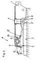
- FIG. 1 shows a longitudinal section through the hinge arm and the base plate in the assembled position
- Fig. 2 shows a plan view of the base plate and the hinge arm mounted thereon partly in section
- Fig. 3 shows a cross section through the hinge arm and the base plate
- the Fig. 4 shows a side view and a top view of a retaining clip
- Fig. 5 shows a longitudinal section through a hinge arm in the position immediately preceding hooking on the base plate
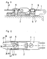
- Fig. 6 shows a longitudinal section through a hinge arm and base plate in one 7 shows a section along the line VII-VII of FIG. 6,
- FIGS. 8 to 11 each show a longitudinal section through the hinge arm and base plate in various embodiments of the invention
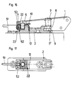
- FIG. 12 shows a plan view 11 partly in section on a hinge arm and base plate according to FIG. 13 shows a longitudinal section tt through the hinge arm and base plate in a further embodiment of the invention
- FIG. 14 shows a top view of the hinge arm and base plate according to FIG. 13, partly in section
- FIGS. 15 and 16 each show a longitudinal section through the hinge arm and base plate in two further embodiments of the Invention
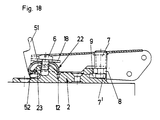
- Fig. 17 shows a plan view of a base plate according to Fig. 16
- Fig. 18 shows the same view as Fig. 16 in the release position of the hinge arm
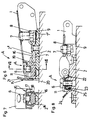
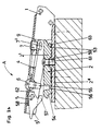
- Fig. 19 shows a longitudinal section through a hinge in the release position
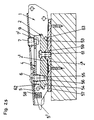
- the 20 shows a longitudinal section with the hinge arm anchored
- FIG. 21 shows the detail of the vein in FIG. 19, FIG.
- FIG. 22 shows a plan view of the hinge arm and base plate, partly in section
- FIG. 23 shows the section along the line A-wire Fig. 20 and the view X of Fig. 20
- Fig. 24 shows a longitudinal section through a hinge arm and a base plate in the position during hanging of the hinge arm in a further embodiment of the invention
- FIG. 25 shows in the same embodiment a longitudinal section through the hinge arm and the base plate with the hinge arm mounted
- FIG. 26 shows in this embodiment a longitudinal section through the hinge arm and the base plate when the intermediate piece is released .
- a resilient retaining clip 3 is inserted into the base plate 2.
- the holding clip 3 has a double web 3 'which bears on the pressure surfaces 2' of the base plate 2 distributed in a triangle and is thus pressed together.
- the hold of the retaining clip 3 in the base plate 2 is therefore relatively strong.
- the hinge arm 1 is at the front, i.e. provided at its end facing the articulated lever in a conventional manner with a joint adjusting screw 7 which is supported in a nut thread in the hinge arm 1 and is held with its head 7 'behind projections 8 of the base plate 2.
- the joint adjustment screw 7 can be tilted in the recess 9 which delimit the projections 8.
- the hinge arm 1 has a tab 10 punched out of its central web, in which there is a longitudinal slot 11 which is open to the rear and through which a clamping screw 6 projects.
- a holding clamp 13 is held by the clamping screw 6.
- This retaining clip 13 has a web 13 'which engages with its edge in a groove 12 in the base plate 2. The groove 12 and the edge of the web 13 'are aligned parallel to the axis of rotation of the hinge.
- the holding clip 13 Opposite the web 13 ', i.e. facing the rear end of the hinge arm 1, the holding clip 13 has a web 13 ", which is provided with a slot 14. The web 3" of the retaining clip 3 projects into the slot 14 in the installed position.
- the hinge arm 1 with the joint adjustment screw 7 is inserted into the recess 9 and then tilted in the direction of arrow A around the head 7 'of the joint adjustment screw 7 as a pivot bearing, as a result of which the retaining clip 13 is pressed onto the holding clip 3.
- the web 3 "of the clip 3 engages in the slot 14 of the web 13" of the holding clip 3 and, as already mentioned, the free edge of the web 13 'of the holding clip 13 projects into the groove 12 of the base plate 2.
- the hinge arm 1 is thus securely anchored on the base plate 2. If an adjustment is to be made in the direction of the furniture door, it is sufficient to turn the joint adjustment screw 7 in a conventional manner.
- the hinge arm 1 can adapt to any angular position due to the flexibility of the tab 1.
- the clamping screw 6 is loosened, whereupon the hinge arm 1 can be moved over the length of the elongated hole 11 or over the depth of the recess 9. After the setting, the clamping screw 6 is tightened again.
- the hinge arm is provided with a joint adjustment screw 7, the head 7 'of which projects into a recess 9 which is delimited by projections 8.
- the hinge arm 1 is in turn provided at its rear end with a slot 11 which is open to the rear.
- the base plate 2 has lateral grooves 16 in the rear area, which run out towards the front and towards the top surface 2 "of the base plate 2. Above the lateral grooves 16, the base plate 2 is provided with inclined surfaces 17 which diverge from the mounting plane 2" 'of the base plate 2 .
- the holding clip 15 has holding brackets 18 on the side, which snap into the grooves 16 of the base plate 2 when the hinge arm 1 is mounted. Furthermore, the holding clip 15 is provided with a resilient web 19 which, when the hinge arm 1 is mounted, lies against the top surface 2 ′′ of the base plate 2 and presses on it.
- the holding clip 15 also has a stop tab 20 which bears on the rear end face of the base plate 2. Above the stop tab 20, a grip part 21 is formed on the holding clip 15 or punched out of the holding clip 15. As in the previously described exemplary embodiment, the holding clip 15 is fastened to the hinge arm 1 by means of a clamping screw 6.
- the hinge arm 1 To mount the hinge arm 1, it is anchored to the base plate 2 by means of the joint adjusting screw 7, which is inserted into the recess 9, as in the previously described exemplary embodiment, and then rotated in the direction of the arrow A.
- the bracket 18 slide laterally over the inclined surfaces 17 and snap into the lateral grooves 16 of the base plate 2. Because the resilient web 19 presses on the base plate 2, the hinge arm 1 is fixed without play.
- the adjustment of the hinge arm 1 in the direction of the furniture door and the depth of the furniture is carried out, as in the embodiment described above, by turning the joint adjustment screw 7 or by opening the clamping screw 6 and moving the hinge arm 1.
- the hinge arm 1 If the hinge arm 1 is to be lifted off the base plate 2, either the clamping screw 6 can be loosened, whereupon the hinge arm 1 is pulled out, or the grip part 21 is pressed forward, whereby the stop tab 20 is lifted off the end face of the base plate 2. Then the hinge arm 1 can be pulled obliquely upwards and forwards out of the base plate 2 along the grooves 16.
- the hinge arm 1 is also mounted on the base plate 2 by first hanging the hinge arm 1 with the joint adjusting screw 7 into the base plate 2, then turning it in the direction of the arrow A and pressing it onto the base plate 2.
- a holding clamp 22 is held by the clamping screw 6, which in turn protrudes through a slot 11 of the hinge arm 1 which is open to the rear, which engages behind a projection 23 of the base plate 2 which projects to the rear and, when the hinge arm 1 is mounted, behind it Tab 23 hooks.
- a grip part 24 is formed on the holding clip 22, by means of which the bracket 25 of the holding clip 22 can be pressed away from the projection 23 in order to detach the hinge arm 1 from the base plate 2.
- the hinge arm 1 is provided with a holding clip 26, and a holding clip 27 is fastened on the base plate 2.
- the retaining clip 26 is pressed onto the retaining clip 27, engages behind a clip 27 'of a clip 27' of the retaining clip 27 and, on the other hand, presses with a clip 26 "onto a clip 27" of the clip 27 achieved firm hold of the hinge arm 1 on the base plate 2.
- the holding clip 26 is provided with a grip part 28, which is formed by a punched-out tab. With the handle part 28, the web 26 'can be lifted from the web 27' of the retaining clip 27 and the hinge arm 1 can be moved freely with respect to the base plate 2.
- the holding clip 26 is attached to the hinge arm 1 by means of an eccentric 29. By turning the eccentric 29, the hinge arm 1 is adjusted in the depth of the furniture.
- the retaining clip 27 is held by the screw 6.
- a holding clamp 30 is fastened on the base plate 2 by means of the clamping screw 6.
- the hinge arm 1 has recesses 31, 32 and webs 33 which protrude from side web to side web of the hinge arm 1 which is essentially designed with a U-profile.
- the holding clip 30 has sections 34, 35 which project upwards, the section 35 being directed obliquely to the hinge arm 1.
- the hinge arm 1 When the hinge arm 1 is assembled, it is in turn pressed onto the holding bracket 30 around the pivot bearing formed by the joint adjusting screw 7 and engages with its webs 33 behind the sections 34, 35 of the holding bracket 30.
- the retaining clip 30 is provided with a longitudinal slot 36 so that the adjustment of the hinge arm 1 in the direction of the depth of the furniture can be done in a conventional manner by loosening the clamping screw 6, whereupon the hinge arm 1 over the length of the longitudinal slot 36 or the depth of the Recess 9 can be moved.
- the holding clamp 37 is in turn fastened on the base plate 2 by means of the clamping screw 6.
- the holding clip 37 is provided with an open slot 38 and thus has two legs 39.
- knobs 40 On the outside of the leg 39 are knobs 40, which engage in recesses 41 of the hinge arm 1 when the hinge arm 1 is mounted.
- the recesses 41 are, for example, rectangular holes.
- the hinge arm 1 has webs 42 which are encompassed by the knobs 40 when the hinge arm 1 has been pivoted onto the base plate 2.
- the retaining clip 37 is resilient so that the legs 39 can be pressed together, whereby the webs 42 are released. The hinge arm 1 can then be pulled off the base plate 2. The adjustment in the depth of the furniture is possible through the slot 38.
- the holding clip 43 is designed as a slide which is guided in guides 44 of the base plate 2.
- the slide 43 is acted upon by a helical spring 45, which is located in a housing of the base plate 2.
- a pin 46 which has an annular groove 47, is attached to the hinge arm 1 by means of the clamping screw 6.
- the clamping screw 6 in turn protrudes through a slot 11 which is open to the rear in the hinge arm 1.
- the holding clip 43 formed by the slide has a keyhole 48 through which the pin 46 protrudes when the hinge arm 1 is mounted. At the rear end, the holding clip 43 is provided with a handle 49.
- the holding clip 43 also has a further longitudinal slot 50 through which a fastening screw for the base plate 2 protrudes.
- the holding clip 43 When the hinge arm 1 is pivoted onto the base plate 2, the holding clip 43 is either pushed back manually against the spring 45 so that the pin 46 can be inserted through the keyhole 48, or the pin 46 has a truncated cone-like configuration at its free end which forms the holding clip 43 pushes back by itself. If the pin 46 is in the position shown in FIG. 13, the spring 45 can insert the retaining clip 43 with the edges of the keyhole 48 into the annular groove 47 of the pin 46, whereupon the hinge arm 1 is held firmly and securely on the base plate 2.
- the adjustment of the hinge arm 1 in the The direction of the furniture door or in the direction of the depth of the furniture is the same as in the previously described exemplary embodiments.
- the holding clip 43 is pressed forward over the handle part 49, whereupon the pin 46 is pivoted out of the keyhole opening 48.
- the clamping screw 6 it would also be possible to loosen the clamping screw 6 and pull out the hinge arm 1 between the clamping screw 6 and the pin 46.
- the holding clip 22 hooks into the projection 23 of the base plate 2.
- the holding clip 22 engages behind the projection 23 on the back of the base plate 2 and projects into a groove 12.
- a pawl 51 is rotatably mounted on an axis 53.
- the pawl 51 is provided with a stop 52.
- the hinge arm 1 is mounted on the base plate 2 as in the previously described embodiment, i.e. hooked into the base plate 2 with the joint adjustment screw 7 and then pivoted so that the retaining clip 22 snaps into the projection 23.
- the pawl 51 As shown in FIG. 18, is pressed upward, as a result of which the leg of the holding clip 22 is pressed off by the projection 23.
- the hinge arm 1 is thus free.
- the parts of the hinge essential to the invention are the hinge arm 1, the base plate 2 and the intermediate piece 4 with the tilting part 5.
- the hinge arm 1 is fastened to the intermediate piece 4 by means of the joint adjustment screw 7, which is supported in a nut thread in the hinge arm 1 and by means of a clamping screw 6, which also serves for the depth adjustment.
- the clamping screw 6 protrudes through a longitudinal slot in the hinge arm 1 and likewise the joint adjusting screw 7 is held with its head 7 'in a recess in the intermediate piece 4 which is designed as an open longitudinal slot 9.
- the hinge arm 1 can be moved along the length of the longitudinal slot and thus adjusted in the depth of the furniture.
- the adjustment in the direction of the furniture door is carried out in a conventional manner by turning the joint adjustment screw 7.
- Both the base plate 2 and the intermediate piece 4 are designed with a U-profile and their legs 2 ', 4' project into one another when the hinge arm 1 is placed on the base plate 2.
- the intermediate piece 4 is provided with a continuous pin 63, which serves as a holding projection of the intermediate piece 4.
- the webs 2 'of the base plate 2 have notches 53 into which the pin 63 can be inserted, so that it is held behind the edge projections of the webs 2'.
- the pin 63 and the notches 53 fulfill the task of the joint adjustment screw 7 and the recess 9 of the previously described exemplary embodiments.
- the base plate 2 is also provided with notches 54.
- the tilting part 5 is supported by means of a pin 64.
- the resilient holding projection 57 is formed on the tilting part 5, which in turn is formed by a pin.
- the tilting part 5 is acted upon by a leg spring 64, which is wound around the bearing pin of the tilting part 5 and is supported with one leg 64 'on the intermediate piece 4 and with the other leg 64 "on the pin 57.
- a cover cap 65 can be provided on the hinge arm 1, which covers the clamping screw 6 and the joint adjustment screw 7 after adjustment.
- a handle part 5 ' is formed on the tilting part 5. If the hinge arm 1 is to be detached from the base plate 2, it is sufficient to press this grip part 5 ', whereupon the pin 57 disengages from the notch 54 and the hinge arm 1 with the intermediate piece 4 can be lifted off the base plate 2.
- FIGS. 24 to 26 The exemplary embodiment according to FIGS. 24 to 26 is described below.
- the hinge arm 1 is in turn attached to the intermediate piece 4 by means of a joint adjusting screw 7 which is supported in a nut thread in the hinge arm 1 and by means of a clamping screw 6 which also serves for the depth adjustment.
- the clamping screw 6 protrudes through a longitudinal slot in the hinge arm 1 and likewise the joint adjustment screw 7 is held with its head 7 ′ in a longitudinal slot in the intermediate piece 4.
- the longitudinal slot forms the recess 9.
- Both the hinge arm 1 and the intermediate piece 4 are designed with a U-profile.
- the intermediate piece 4 is provided with a continuous pin 63, which serves as a holding projection of the intermediate piece 4.
- the base plate 2 has a notch 53 in the front, into which the pin 63 can be suspended, so that it is held on the base plate 2.
- the base plate 2 is also provided with a notch 54.
- the rocker arm 5 is supported at the rear end of the intermediate piece 4.
- the hook-like projection 57 is formed on the rocker arm 5.
- the rocker arm 5 is acted upon by a helical spring 58 which is mounted in a recess in the rocker arm 5 and is supported at one end on the hinge arm 1.
- the clamping screw 6 for the depth adjustment has a centering projection 55 which projects into a corresponding opening 56 in the base plate 2.
- the centering projection 55 is a cone and the opening 56 is funnel-shaped. In this way, the hinge arm 1 is immediately correctly positioned.
- the distances between the pin 63 and the centering lug 55 on the one hand and the notch 53 and the opening 56 on the other hand are, as already mentioned, chosen so that a slight tensioning occurs when the intermediate piece 4 is pressed on. As a result, the intermediate piece 4 is held on the base plate 2 without play.
- a handle part 5 ' is formed on the tilting part 5. If the hinge arm 1 is to be detached from the base plate 2, it suffices to raise this grip part 5 ', whereupon the projection 57 disengages from the notch 54 and the hinge arm 1 with the intermediate piece 4 can be lifted off the base plate 2.
- the nose 62 presses on the base plate 2 and acts like a lever. In this way, it is possible to easily loosen the centering projection 55 despite the tension.
- the clamping screw 6 is loosened and the upper part 2 'of the base plate 2 is displaced at the lower part 2 ".
- the guide 59 prevents the hinge arm 1 from tilting. After the height adjustment has taken place, the clamping screw 6 is tightened.
- top and bottom used in the course of the description refer to the figures in the drawing and not to the position of the hinge mounted on the furniture.
- hinge arm is hooked directly or indirectly onto the base plate at one end and is then rotated about this pivot bearing, whereupon the other end snaps into a latch-like locking.
- the hinge arm is hooked in at the end which faces the joint or the joint levers.
Landscapes
- Engineering & Computer Science (AREA)
- Mechanical Engineering (AREA)
- Hinges (AREA)
- Vehicle Step Arrangements And Article Storage (AREA)
- Superstructure Of Vehicle (AREA)
- Closing And Opening Devices For Wings, And Checks For Wings (AREA)
Abstract
Description
Die Erfindung bezieht sich auf ein Scharnier mit einem auf einer Grundplatte verstellbar gehalte- nen Scharnierarm, mit einer Fugenverstell- schraube od.dgl. und einer in der Tiefe des Möbels wirkenden Verstelleinrichtung, wobei der Scharnierarm an zwei über die Länge des Scharnierarmes versetzten Lagerstellen über ein Zwischenstück mittelbar an der Grundplatte gehalten ist, indem das Zwischenstück an einer ersten Lagerstelle formschlüssig in die Grundplatte einhängbar und an einer zweiten Lagerstelle durch eine federnde Rastverbindung gehalten ist.The invention relates to a hinge with an adjustable hinge arm on a base plate, with a joint adjusting screw or the like. and an adjustment device acting in the depth of the piece of furniture, the hinge arm being indirectly held on the base plate at two bearing points offset along the length of the hinge arm by means of an intermediate piece by the intermediate piece being able to be positively hooked into the base plate at a first bearing point and through at a second bearing point a resilient locking connection is held.
Bei herkömmlichen Scharnieren ist der Scharnierarm mittels einer Klemmschraube auf der Grundplatte befestigt, wobei diese Klemmschraube im allgemeinen durch ein Langloch ragt, um so eine Verstellung des Scharnierarmes in der Tiefe des Möbels möglich zu machen.In conventional hinges, the hinge arm is fastened to the base plate by means of a clamping screw, this clamping screw generally protruding through an elongated hole, in order to make it possible to adjust the hinge arm in the depth of the furniture.
In letzter Zeit sind auch Schnappverbindungen zur Befestigung des Scharnierarmes an der Grundplatte bekannt geworden. So zeigen zum Beispiel die DE-A-30 26 796 und 30 39 328 Scharniere mit einem Scharnierarm und einer Befestigungsplatte, bei dem durch Einsetzen des Scharnierarmes in eine Führung der Befestigungsplatte und Verschieben desselben in Längsrichtung die beiden miteinander zu verriegelnden Teile ineinander einschnappen. Eine ähnliche Verankerung eines Scharnierarmes auf einer Grundplatte ist in der DE-A-24 60 127 gezeigt. Die DE-A-32 41 284 zeigt ein Scharnier, bei dem der Scharnierarm in seitliche Führungen einer Grundplatte einschiebbar und mittels eines Exzenters auf der Grundplatte klemmbar ist.Recently, snap connections for fastening the hinge arm to the base plate have also become known. For example, DE-A-30 26 796 and 30 39 328 show hinges with a hinge arm and a fastening plate, in which, by inserting the hinge arm into a guide of the fastening plate and displacing it in the longitudinal direction, the two parts to be locked snap together. A similar anchoring of a hinge arm on a base plate is shown in DE-A-24 60 127. DE-A-32 41 284 shows a hinge in which the hinge arm can be inserted into lateral guides of a base plate and clamped on the base plate by means of an eccentric.
Die DE-A-3 119 571 beschreibt ein Scharnier, bei dem der Scharnierarm mittels einer Klemmschraube, die auch der Tiefenverstellung dient, mit einem Zwischenstück verbunden ist. Die Grundplatte ist mittels dicker Dübelzapfen in die Möbelwand eingesetzt. In die Dübelzapfen, die hohl sind, ragen Haken des Zwischenstückes. Dabei wird bei der Montage das Zwischenstück mit einem vorderen Haken in die Grundplatte vorne eingehängt und dann nach hinten gekippt. Der hintere Haken des Zwischenstückes greift an einem federnden Haken der Grundplatte, der sich im hinteren Dübelzapfen befindet, an. Die Ausbildung der Grundplatte ist relativ kompliziert. Das einmal auf der Grundplatte verankerte Zwischenstück ist nur schwer lösbar.DE-A-3 119 571 describes a hinge in which the hinge arm is connected to an intermediate piece by means of a clamping screw which also serves for the depth adjustment. The base plate is inserted into the furniture wall using thick dowel pins. Hooks of the intermediate piece protrude into the dowel pins, which are hollow. During assembly, the intermediate piece is attached to the front of the base plate with a front hook and then tilted back. The rear hook of the intermediate piece engages on a resilient hook of the base plate, which is located in the rear dowel pin. The formation of the base plate is relatively complicated. The intermediate piece once anchored on the base plate is difficult to remove.
Die DE-A-3 302 312 zeigt ein Scharnier, bei dem der Scharnierarm mittels der Fugenverstellschraube vorne in die Grundplatte eingeschoben wird. Fixiert wird der Scharnierarm durch eine am hinteren Ende der Grundplatte angeordnete Klemmschraube, die auch der Tiefenverstellung dient und die durch ein nach hinten offenes Langloch des Scharnierarmes ragt.DE-A-3 302 312 shows a hinge in which the hinge arm is pushed into the base plate at the front by means of the joint adjustment screw. The hinge arm is fixed by a clamping screw located at the rear end of the base plate, which also serves for depth adjustment and which projects through an elongated hole in the hinge arm that is open to the rear.
Bei der Montage muß der Scharnierarm mit seinem hinteren Ende unter den Kopf dieser Klemmschraube, die in die Grundplatte eingeschraubt ist, geschoben werden. Der Scharnierarm wird daher nicht, wie bei der Konstruktion gemäß der DE-A-3 119 571 in die Grundplatte eingehängt und anschließend gekippt, um automatisch verriegelt zu werden, sondern er wird von vorne in die Grundplatte eingeschoben und ist erst dann gehalten, wenn die Klemmschraube angezogen wird.During assembly, the hinge arm must be pushed with its rear end under the head of this clamping screw, which is screwed into the base plate. The hinge arm is therefore not, as in the construction according to DE-A-3 119 571, suspended in the base plate and then tilted to be automatically locked, but is pushed into the base plate from the front and is only held when the Clamping screw is tightened.
MitAusnahme des Scharnieres gemäß der DE-A-3 302 312 haben die vorhergehend beschriebenen Scharnierarmverankerungen den Vorteil, daß der Scharnierarm beim Zusammenbau des Möbels sehr schnell auf der Grundplatte festgelegt werden kann und daß weiters zur Montage kein Werkzeug gebraucht wird. Dieser Vorteil ist nicht zu unterschätzen, da beim Einhängen der Scharnierarme der Türflügel gehalten werden muß. Wird zum Beispiel der Türflügel mit einer Hand gehalten und der gerade aufzusetzende Scharnierarm mit der anderen, dann bedarf es, falls die Arretierung des Scharnierarmes mittels einer Klemmschraube erfolgt, in vielen Fällen einer zweiten Person, die die Klemmschraube mit einem Schraubenzieher anzieht.With the exception of the hinge according to DE-A-3 302 312, the hinge arm anchorings described above have the advantage that the hinge arm can be fixed very quickly on the base plate when the furniture is being assembled, and that furthermore no tools are required for assembly. This advantage should not be underestimated, since the door leaf must be held when the hinge arms are attached. If, for example, the door leaf is held with one hand and the hinge arm to be put on with the other, then in many cases, if the hinge arm is locked by means of a clamping screw, a second person is required to tighten the clamping screw with a screwdriver.
Ein Nachteil der Scharniere, bei denen der Scharnierarm oder das Zwischenstück von vorne in die Grundplatte einschiebbar ist, ist, daß es leicht zu einem Verkanten kommt. Dies ist insbesondere bei hohen Türen, die viele Scharniere tragen, der Fall. In den meisten Fällen muß dabei der Scharnierarm fast über die gesamte Länge der Grundplatte verschoben werden.A disadvantage of the hinges, in which the hinge arm or the intermediate piece can be inserted into the base plate from the front, is that it can easily tilt. This is particularly the case with tall doors that have many hinges. In most cases, the hinge arm must be moved almost over the entire length of the base plate.
Aufgabe der Erfindung ist es, ein Scharnier mit einer federnden Rastverriegelung, bei dem eine Tiefenverstellung des Scharnierarmes möglich ist, insofern zu verbessern, als daß es einfach in der Konstruktion ist und der Scharnierarm mit dem Zwischenstück leicht auf die Grundplatte aufgesetzt und von dieser wieder gelöst werden kann. Die Grundplatte soll dabei mittels Schrauben oder herkömmlichen Dübel am Möbel befestigt sein.The object of the invention is to improve a hinge with a resilient locking lock, in which a depth adjustment of the hinge arm is possible, in that it is simple in construction and the hinge arm with the intermediate piece is easily placed on the base plate and released from it can be. The base plate should be attached to the furniture using screws or conventional dowels.
Dies wird erfindungsgemäß dadurch erreicht, daß am Zwischenstück bei der zweiten Lagerstelle ein Kipphebel auf einer Achse drehbar lagert, der einen hakenartigen Vorsprung aufweist, der in einer Kerbe der Grundplatte einrastet, daß das Zwischenstück im Querschnitt U-Profil aufweist und an seiner ersten Lagerstelle mit einem durchgehenden Stiftversehen ist, der auf den beiden Seitenstegen des Zwischenstükkes lagert und der als ein Haltevorsprung des Zwischenstückes dient und daß die Grundplatte an dieser ersten Lagerstelle eine Kerbe aufweist, in die der Stift einhängbar ist, wobei der Stift und die Kerbe ein Drehlager bilden, um das das Zwischenstück mit dem Scharnierarm drehbar ist und daß der Kipphebel, der zwischen den beiden Seitenstegen des Zwischenstückes lagert, von einer Feder beaufschlagt ist.This is achieved according to the invention in that a rocker arm is rotatably supported on an axis at the intermediate piece at the second bearing point, which has a hook-like projection which engages in a notch in the base plate, that the intermediate piece has a U-profile in cross section and at its first bearing point with a continuous pin is provided, which is supported on the two side webs of the intermediate piece and which serves as a holding projection of the intermediate piece and that the base plate has a notch at this first bearing point, into which the pin can be hung, the pin and the notch forming a pivot bearing, around which the intermediate piece with the hinge arm is rotatable and that the rocker arm, which is supported between the two side webs of the intermediate piece, by a spring is acted upon.
Ein Ausführungsbeispiel der Erfindung sieht vor, daß der Scharnierarm in das Ende der Grundplatte, das dem Scharniergelenk zugewendet ist, mittels der Fugenverstellschraube drehbar eingehängt ist, wobei die Fugenverstellschraube zusammen mit Vorsprüngen der Grundplatte das Drehlager bildet, und daß am Scharnierarm und/oder der Grundplatte eine federnde oder federbeaufschlagte Halteklammer vorgesehen ist, die das um das Drehlager des Scharnierarmes schwenkbare Scharnierarmende hält, indem sie bei einem Anschlagteil des korrespondierenden Scharnierteiles oder einer daran befestigten Halteklammer einrastet, wobei die Halteklammer mittels einer Klemmschraube, die der Tiefenverstellung des Scharnierarmes dient, gehalten ist.An embodiment of the invention provides that the hinge arm is rotatably mounted in the end of the base plate, which faces the hinge joint, by means of the joint adjustment screw, the joint adjustment screw forming the pivot bearing together with projections of the base plate, and that on the hinge arm and / or the base plate a resilient or spring-loaded retaining clip is provided which holds the hinge arm end which can be pivoted about the pivot bearing of the hinge arm by snapping into a stop part of the corresponding hinge part or a retaining clip attached thereto, the retaining clip being held by means of a clamping screw which serves to adjust the depth of the hinge arm .
Vorteilhaft ist vorgesehen, daß die Halteklammer zwei Stege aufweist, die parallel zu der Drehachse des Scharnieres ausgerichtet sind, wovon einer in einer Nut der Grundplatte einrastet, während der andere einen Schlitz od.dgl. aufweist, in den ein Steg der zweiten Halteklammer ragt, die in der Grundplatte gehalten ist.It is advantageously provided that the retaining clip has two webs which are aligned parallel to the axis of rotation of the hinge, one of which engages in a groove in the base plate, while the other has a slot or the like. has, in which a web of the second retaining clip protrudes, which is held in the base plate.
Ein Ausführungsbeispiel der Erfindung sieht vor, daßdie zweite Halteklammer einen federnden, umgebogenen Doppelsteg aufweist, mit dem sie klemmend in die Grundplatte eingeschoben ist.An embodiment of the invention provides that the second retaining clip has a resilient, bent double web, with which it is inserted into the base plate in a clamping manner.
Vorteilhaft ist es, wenn der Doppelsteg in der Grundplatte an drei Flächen anliegt, die im Querschnitt der Grundplatte im Dreieck angeordnet sind.It is advantageous if the double web rests in the base plate on three surfaces which are arranged in a triangle in the cross section of the base plate.
Ein weiteres Ausführungsbeispiel der Erfindung sieht vor, daß die am Scharnierarm mittels der Klemmschraube gehaltene Halteklammer seitliche Haltebügel aufweist, die in seitlichen Nuten der Grundplatte einrasten, wobei vorteilhaft die Nuten zur vorderen Stirnfläche oder schräg nach vorne zur Deckfläche der Grundplatte auslaufen und die Halteklammer einen Anschlaglappen aufweist, der an der hinteren Stirnfläche der Grundplatte oder einem korrespondierenden Vorsprung federnd anliegt.Another embodiment of the invention provides that the retaining clip held on the hinge arm by means of the clamping screw has lateral retaining clips which engage in lateral grooves in the base plate, the grooves advantageously running out to the front end face or obliquely forward to the top surface of the base plate and the retaining clip a stop tab has, which resiliently abuts the rear end face of the base plate or a corresponding projection.
In einem Ausführungsbeispiel der Erfindung ist vorgesehen, daß die am Scharnierarm mittels der Klemmschraube gehaltene Halteklammer bei einem nach hinten auskragenden Vorsprung der Grundplatte einhakt.In one embodiment of the invention it is provided that the holding clip held on the hinge arm by means of the clamping screw hooks into a projection of the base plate projecting to the rear.
Vorteilhaft ist vorgesehen, daß die Halteklammer einen Längsschlitz aufweist, durch den die Klemmschraube ragt, die in einem Muttergewinde der Grundplatte lagert, und daß der Langschlitz in der Halteklammer offen ist und derart zwei Schenkel bildet, die außen Noppen aufweisen, die in Ausnehmungen in den Seitenstegen des Scharnierarmes einrasten.It is advantageously provided that the retaining clip has a longitudinal slot through which the clamping screw protrudes, which is supported in a nut thread of the base plate, and that the elongated slot in the retaining clip is open and thus forms two legs which have knobs on the outside, which in recesses in the Snap the side bars of the hinge arm into place.
Ein weiteres Ausführungsbeispiel der Erfindung sieht vor, daß der federnde Vorsprung von einem in der Grundplatte gelagerten, federbeaufschlagten Schieber gebildet wird, der in Führungen der Grundplatte geführt ist und ein Loch aufweist, durch das ein am Scharnierairm befestigter Zapfen ragt, der eine seitliche Nut aufweist, in der der Schieber mit seinem Lochrand einrastet, sodaß das freie Ende des Scharnierarmes gegen Abheben von der Grundplatte gesichert ist.Another embodiment of the invention provides that the resilient projection is formed by a spring-loaded slide mounted in the base plate, which is guided in guides of the base plate and has a hole through which a pin attached to the hinge arm projects, which has a lateral groove , in which the slide engages with its hole edge, so that the free end of the hinge arm is secured against lifting off the base plate.
Nachstehend werden Ausführungsbeispiele der Erfindung anhand der Figuren der beiliegenden Zeichnungen eingehend beschrieben.Exemplary embodiments of the invention are described in detail below with reference to the figures in the accompanying drawings.
Die Fig. 1 zeigt einen Längsschnitt durch den Scharnierarm und die Grundplatte in montierter Stellung, die Fig. 2 zeigt eine Draufsicht auf die Grundplatte und darauf montiertem Scharnierarm teilweise im Schnitt, die Fig. 3 zeigt einen Querschnitt durch den Scharnierarm und die Grundplatte, die Fig. 4 zeigt eine Seitenansicht und eine Draufsicht auf eine Halteklammer, die Fig. 5 zeigt einen Längsschnitt durch einen Scharnierarm in der Stellung, die dem Einhaken auf der Grundplatte unmittelbar vorangeht, die Fig. 6 zeigt einen Längsschnitt durch einen Scharnierarm und Grundplatte bei einem weiteren Ausführungsbeispiel der Erfindung, die Fig. 7 zeigt einen Schnitt nach der Linie VII-VII der Fig. 6, die Fig. 8 bis 11 zeigen jeweils einen Längsschnitt durch Scharnierarm und Grundplatte bei verschiedenen Ausführungsbeispielen der Erfindung, die Fig. 12 zeigt eine Draufsicht auf einen Scharnierarm und Grundplatte gemäß Fig. 11 teilweise im Schnitt, die Fig. 13 zeigt einen Längsschnitt durch Scharnierarm und Grundplatte bei einem weiteren Ausführungsbeispiel der Erfindung, die Fig. 14 zeigt eine Draufsicht auf Scharnierarm und Grundplatte gemäß Fig. 13 teilweise im Schnitt, die Fig. 15 und 16 zeigen je einen Längsschnitt durch Scharnierarm und Grundplatte bei zwei weiteren Ausführungsbeispielen der Erfindung, die Fig. 17 zeigt eine Draufsicht auf eine Grundplatte gemäß Fig. 16, die Fig. 18 zeigt die gleiche Ansicht wie Fig. 16 in der Lösestellung des Scharnierarmes, die Fig. 19 zeigt einen Längsschnitt durch ein Scharnier in der Lösestellung, die Fig. 20 zeigt einen Längsschnitt bei verankertem Scharnierarm, die Fig. 21 zeigt den Ausschnitt Ader Fig. 19, die Fig. 22 zeigt eine Draufsicht auf Scharnierarm und Grundplatte teilweise im Schnitt, die Fig. 23 zeigt den Schnitt nach der Linie A-Ader Fig. 20 und die AnsichtX der Fig. 20, die Fig. 24 zeigt einen Längsschnitt durch einen Scharnierarm und eine Grundplatte in der Stellung während des Einhängens des Scharnierarmes bei einem weiteren Ausführungsbeispiel der Erfindung, die Fig. 25 zeigt beim selben Ausführungsbeispiel einen Längsschnitt durch den Scharnierarm und die Grundplatte bei montiertem Scharnierarm, und die Fig. 26 zeigt bei diesem Ausführungsbeispiel einen Längsschnitt durch den Scharnierarm und die Grundplatte beim Lösen des Zwischenstückes.Fig. 1 shows a longitudinal section through the hinge arm and the base plate in the assembled position, Fig. 2 shows a plan view of the base plate and the hinge arm mounted thereon partly in section, Fig. 3 shows a cross section through the hinge arm and the base plate, the Fig. 4 shows a side view and a top view of a retaining clip, Fig. 5 shows a longitudinal section through a hinge arm in the position immediately preceding hooking on the base plate, Fig. 6 shows a longitudinal section through a hinge arm and base plate in one 7 shows a section along the line VII-VII of FIG. 6, FIGS. 8 to 11 each show a longitudinal section through the hinge arm and base plate in various embodiments of the invention, FIG. 12 shows a
In den Figuren derZeichnungen sind die nicht unmittelbar zur Erfindung gehörenden Teile des Scharnieres, wie der Scharniertopf und die Gelenkhebel, nicht gezeigt, sie können in beliebiger Art nach dem bekannten Stand der Technik gefertigt sein.In the figures of the drawings, the parts of the hinge not directly belonging to the invention, such as the hinge cup and the articulated lever, are not shown, they can be made in any way according to the known prior art.
Im Ausführungsbeispiel nach den Fig. 1 bis 5 ist in der Grundplatte 2 eine federnde Halteklammer 3 eingeschoben. Die Halteklammer 3 weist einen Doppelsteg 3' auf, der an im Dreieck verteilten Druckflächen 2' der Grundplatte 2 anliegt und so zusammengedrückt wird. Der Halt der Halteklammer 3 in der Grundplatte 2 ist daher relativ stark.In the exemplary embodiment according to FIGS. 1 to 5, a
Der Scharnierarm 1 ist vorne, d.h. bei seinem dem Gelenkhebel zugewendeten Ende in herkömmlicherWeise mit einer Fugenverstellschraube 7 versehen, die in einem Muttergewinde im Scharnierarm 1 lagert und mit ihrem Kopf 7' hinter Vorsprüngen 8 der Grundplatte 2 gehalten ist. Die Fugenverstellschraube 7 ist in der Ausnehmung 9, die die Vorsprünge 8 begrenzen, kippbar.The
Am hinteren Ende weist der Scharnierarm 1 eine aus seinem Mittelsteg ausgestanzte Lasche 10 auf, in der sich ein nach hinten offener Längsschlitz 11 befindet, durch den eine Klemmschraube 6 ragt. Von der Klemmschraube 6 wird eine Halteklammer 13 gehalten. Diese Halteklammer 13 weist einen Steg 13' auf, der mit seinem Rand in eine Nut 12 in der Grundplatte 2 eingreift. Die Nut 12 und der Rand des Steges 13' sind parallel zu der Drehachse des Scharnieres ausgerichtet.At the rear end, the
Gegenüberliegend dem Steg 13', d.h. dem hinteren Ende des Scharnierarmes 1 zugewendet, weist die Halteklammer 13 einen Steg 13" auf, der mit einem Schlitz 14 versehen ist. In den Schlitz 14 ragt in Montagelage der Steg 3" der Halteklammer 3.Opposite the web 13 ', i.e. facing the rear end of the
Wie aus der Fig. 5 ersichtlich, wird bei der Montage des Scharnierarmes 1 der Scharnierarm 1 mit der Fugenverstellschraube 7 in die Ausnehmung 9 eingeschoben und dann in der Richtung des Pfeiles A um den Kopf 7' der Fugenverstellschraube 7 als Drehlager gekippt, wodurch die Halteklammer 13 auf die Halteklammer 3 aufgedrückt wird. In der endgültigen Montagestellung rastet der Steg 3" der Klammer 3 im Schlitz 14 des Steges 13" der Halteklammer 3 ein und der freie Rand des Steges 13' der Halteklammer 13 ragt, wie bereits gesagt, in die Nut 12 der Grundplatte 2. Der Scharnierarm 1 ist somit sicher auf der Grundplatte 2 verankert. Soll eine Verstellung in der Richtung der Möbeltürfuge erfolgen, genügt es, die Fugenverstellschraube 7 auf herkömmliche Art und Weise zu verdrehen. Der Scharnierarm 1 kann sich auf Grund der Nachgiebigkeit des Lappens 1 jeder Winkellage anpassen.As can be seen from FIG. 5, when installing the
Zur Verstellung des Scharnierarmes 1 in der Tiefe des Möbels wird die Klemmschraube 6 gelöst, worauf der Scharnierarm 1 über die Länge des Langloches 11 bzw. über die Tiefe der Ausnehmung 9 verschoben werden kann. Nach erfolgter Einstellung wird die Klemmschraube 6 wieder angezogen.To adjust the
Um den Scharnierarm 1 von der Grundplatte 2 zu lösen, genügt es, den Steg 3" der Halteklammer 3 mittels eines Schraubenziehers zurückzudrücken. Es kann auch die Klemmschraube 6 gelöst und der Scharnierarm 1 nach vorne abgezogen werden.In order to detach the
Im Ausführungsbeispiel nach den Fig. 6 und 7 findet nur eine Halteklammer 15 Verwendung. Am vorderen Ende ist der Scharnierarm wie beim zuvor beschriebenen Ausführungsbeispiel mit einer Fugenverstellschraube 7 versehen, deren Kopf 7' in eine Ausnehmung 9 ragt, die von Vorsprüngen 8 begrenzt wird.In the exemplary embodiment according to FIGS. 6 and 7, only one holding clip 15 is used. At the front end, as in the previously described exemplary embodiment, the hinge arm is provided with a
Der Scharnierarm 1 ist an seinem hinteren Ende wiederum mit einem nach hinten offenen Schlitz 11 versehen.The
Die Grundplatte 2 weist im hinteren Bereich seitliche Nuten 16 auf, die nach vorne und zur Deckfläche 2" der Grundplatte 2 hin auslaufen. Oberhalb der seitlichen Nuten 16 ist die Grundplatte 2 mit Schrägflächen 17 versehen, die zur Montageebene 2"' der Grundplatte 2 divergieren. Die Halteklammer 15 weist seitlich Haltebügel 18 auf, die bei montiertem Scharnierarm 1 in den Nuten 16 der Grundplatte 2 einrasten. Weiters ist die Halteklammer 15 mit einem federnden Steg 19 versehen, der bei montiertem Scharnierarm 1 an der Deckfläche 2" der Grundplatte 2 anliegt und auf diese drückt.The
Die Halteklammer 15 weist weiters einen Anschlaglappen 20 auf, der an der hinteren Stirnfläche der Grundplatte 2 anliegt. Oberhalb des Anschlaglappens 20 ist an der Halteklammer 15 ein Griffteil 21 ausgebildet bzw. aus der Halteklammer 15 ausgestanzt. Die Halteklammer 15 ist wie beim zuvor beschriebenen Ausführungsbeispiel mittels einer Klemmschraube 6 am Scharnierarm 1 befestigt.The holding clip 15 also has a
Zur Montage des Scharnierarmes 1 wird dieser wie beim zuvor beschriebenen Ausführungsbeispiel mittels der Fugenverstellschraube 7, die in die Ausnehmung 9 eingeschoben wird, auf der Grundplatte 2 verankert und dann in der Richtung des Pfeiles Agedreht. Die Haltebügel 18 rutschen seitlich über die Schrägflächen 17 und schnappen in den seitlichen Nuten 16 der Grundplatte 2 ein. Dadurch, daß der federnde Steg 19 auf die Grundplatte 2 drückt, ist der Scharnierarm 1 spielfrei fixiert.To mount the
Die Verstellung des Scharnierarmes 1 in der Richtung der Möbeltürfuge und der Tiefe des Möbels erfolgt wie beim zuvor beschriebenen Ausführungsbeispiel durch Verdrehen der Fugenverstellschraube 7 bzw. durch Öffnen der Klemmschraube 6 und Verschieben des Scharnierarmes 1.The adjustment of the
Soll der Scharnierarm 1 von der Grundplatte 2 abgehoben werden, kann entweder die Klemmschraube 6 gelöst werden, worauf der Scharnierarm 1 herausgezogen wird, oder es wird der Griffteil 21 nach vorne gedrückt, wodurch der Anschlaglappen 20 von der Stirnfläche der Grundplatte 2 abgehoben wird. Dann kann der Scharnierarm 1 entlang der Nuten 16 schräg nach oben und nach vorne aus der Grundplatte 2 herausgezogen werden.If the
Bei den nachfolgenden Ausführungsbeispielen wird lediglich nur auf die hintere Verankerung des Scharnierarmes 1 auf der Grundplatte 2 Bezug genommen. In allen Fällen ist die vordere Verankerung mittels der Fugenverstellschraube 7, die in der von Vorsprüngen 8 begrenzten Ausnehmung 9 einrastet, gleich. In allen Fällen erfolgt die Montage des Scharnierarmes 1 auf der Grundplatte 2 auch dadurch, daß der Scharnierarm 1 zuerst mit der Fugenverstellschraube 7 in die Grundplatte 2 eingehängt wird, dann in der Richtung des Pfeiles Agedreht und auf die Grundplatte 2 aufgedrückt wird.In the following exemplary embodiments is only referred to the rear anchorage of the
Im Ausführungsbeispiel nach der Fig. 8 wird von der Klemmschraube 6, die wiederum durch einen nach hinten offenen Schlitz 11 des Scharnierarmes 1 ragt, eine Halteklammer 22 gehalten, die einen nach hinten auskragenden Vorsprung 23 der Grundplatte 2 hintergreift und bei montiertem Scharnierarm 1 hinter diesem Vorsprung 23 einhakt.In the exemplary embodiment according to FIG. 8, a holding
An der Halteklammer 22 ist ein Griffteil 24 ausgebildet, mittels dem der Bügel 25 der Halteklammer 22 vom Vorsprung 23 weggedrückt werden kann, um den Scharnierarm 1 von der Grundplatte 2 zu lösen. Zum Montieren des Scharnierarmes 1 genügt es, diesen mit der Halteklammer 22 auf die Grundplatte 2 aufzudrücken. Im Ausführungsbeispiel nach der Fig. 9 ist der Scharnierarm 1 mit einer Halteklammer 26 versehen, und auf der Grundplatte 2 ist eine Halteklammer 27 befestigt. Bei montiertem Scharnierarm 1 ist die Halteklammer 26 auf die Halteklammer 27 aufgedrückt, hintergreift mit einem Steg 26' einer Steg 27' der Halteklammer 27 und drückt andererseits mit einem Steg 26" auf einen Steg 27" der Halteklammer 27. Auf diese Art wird wiederum ein fester Halt des Scharnierarmes 1 auf der Grundplatte 2 erzielt.A
Die Halteklammer 26 ist mit einem Griffteii 28 versehen, der von einem ausgestanzten Lappen gebildet wird. Mit dem Griffteil 28 kann der Steg 26' vom Steg 27' der Halteklammer 27 abgehoben werden und der Scharnierarm 1 ist in bezug auf die Grundplatte 2 frei bewegbar.The holding
Die Halteklammer 26 ist am Scharnierarm 1 mittels eines Exzenters 29 befestigt. Durch Verdrehen des Exzenters 29 wird der Scharnierarm 1 in der Tiefe des Möbels verstellt. Die Halteklammer 27 wird von der Schraube 6 gehalten.The holding
Im Ausführungsbeispiel nach der Fig. 10 ist eine Halteklammer 30 mittels der Klemmschraube 6 auf der Grundplatte 2 befestigt. Der Scharnierarm 1 weist Ausnehmungen 31, 32 und Stege 33 auf, die von Seitensteg zu Seitensteg des im wesentlichen mit U-Profil ausgeführten Scharnierarmes 1 ragen.In the exemplary embodiment according to FIG. 10, a holding
Die Halteklammer 30 weist nach oben abstehende Abschnitte 34, 35 auf, wobei der Abschnitt 35 schräg zum Scharnierarm 1 gerichtet ist.The holding
Bei der Montage des Scharnierarmes 1 wird dieserwiederum um das von der Fugenverstellschraube 7 gebildete Drehlager auf die Halteklammer 30 aufgedrückt und rastet mit seinen Stegen 33 hinter den Abschnitten 34, 35 der Halteklammer 30 ein.When the
Die Halteklammer 30 ist mit einem Längsschlitz 36 versehen, so daß die Verstellung des Scharnierarmes 1 in der Richtung der Tiefe des Möbels in herkömmlicher Art durch Lösen der Klemmschraube 6 erfolgen kann, worauf der Scharnierarm 1 über die Länge des Längsschlitzes 36 bzw. der Tiefe der Ausnehmung 9 verschoben werden kann.The retaining
Im Ausführungsbeispiel nach den Fig. 11 und 12 ist die Halteklammer 37 wiederum mittels der Klemmschraube 6 auf der Grundplatte 2 befestigt. Die Halteklammer 37 ist mit einem offenen Schlitz 38 versehen und weist so zwei Schenkel 39 auf. Außen an dem Schenkel 39 sind Noppen 40 ausgebidet, die bei montiertem Scharnierarm 1 in Ausnehmungen 41 des Scharnierarmes 1 eingreifen. Die Ausnehmungen 41 sind beispielsweise rechteckige Löcher. Der Scharnierarm 1 weist an seinem hinteren Ende Stege 42 auf, die von den Noppen 40, wenn der Scharnierarm 1 auf die Grundplatte 2 geschwenkt wurde, umfaßt werden. Die Halteklammer 37 ist federnd, so daß die Schenkel 39 zusammengedrückt werden können, wodurch die Stege 42 freigegeben werden. Darauf kann der Scharnierarm 1 von der Grundplatte 2 abgezogen werden. Die Verstellung in der Tiefe des Möbels ist durch den Schlitz 38 möglich.In the exemplary embodiment according to FIGS. 11 and 12, the holding
Im Ausführungsbeispiel nach den Fig. 13 und 14 ist die Halteklammer 43 als Schieber ausgeführt, der in Führungen 44 der Grundplatte 2 geführt ist. Der Schieber43 wird von einer Schraubenfeder45 beaufschlagt, die sich in einem Gehäuse der Grundplatte 2 befindet.In the exemplary embodiment according to FIGS. 13 and 14, the holding
Am Scharnierarm 1 ist mittels der Klemmschraube 6 ein Zapfen 46 befesitgt, der eine Ringnut 47 aufweist. Die Klemmschraube 6 ragt wiederum durch einen nach hinten offenen Schlitz 11 im Scharnierarm 1.A
Die vom Schieber gebildete Halteklammer 43 weist ein Schlüsselloch 48 auf, durch das bei montiertem Scharnierarm 1 der Zapfen 46 ragt. Am hinteren Ende ist die Halteklammer 43 mit einem Griff 49 versehen. Die Halteklammer 43 weist noch einen weiteren Längsschlitz 50 auf, durch den eine Befestigungsschraube für die Grundplatte 2 ragt.The holding
Beim Aufschwenken des Scharnierarmes 1 auf die Grundplatte 2 wird die Halteklammer43 entweder händisch gegen die Feder45 zurückgedrückt, so daß der Zapfen 46 durch das Schlüsselloch 48 gesteckt werden kann, oder es weist der Zapfen 46 an seinem freien Ende eine kegelstumpfartige Ausbildung auf, die die Halteklammer 43 von selbst zurückdrückt. Ist der Zapfen 46 in der in der Fig. 13 gezeigten Position, kann die Feder 45 die Halteklammer 43 mit den Rändern des Schlüsselloches 48 in die Ringnut 47 des Zapfens 46 einschieben, worauf der Scharnierarm 1 fest und sicher auf der Grundplatte 2 gehalten ist.When the
Die Verstellung des Scharnierarmes 1 in der Richtung der Möbeltürfuge bzw. in der Richtung der Tiefe des Möbels erfolgt gleich wie bei den zuvor beschriebenen Ausführungsbeispielen.The adjustment of the
Zum Lösen des Scharnierarmes 1 wird die Halteklammer 43 über den Griffteil 49 nach vorne gedrückt, worauf der Zapfen 46 aus der Schlüssellochöffnung 48 herausgeschwenkt wird. Selbstverständlich wäre es auch möglich, die Klemmschraube 6 zu lösen und den Scharnierarm 1 zwischen Klemmschraube 6 und Zapfen 46 herauszuziehen.To release the
Im Ausführungsbeispiel nach der Fig. 15 hakt die Halteklammer 22 bei dem Vorsprung 23 der Grundplatte 2 ein.In the exemplary embodiment according to FIG. 15, the holding
Im Ausführungsbeispiel nach den Fig. 16 bis 18 hintergreift die Halteklammer 22 einerseits den Vorsprung 23 an der Rückseite der Grundplatte 2 und ragt andererseits in eine Nut 12. Am hinteren Ende der Grundplatte 2 ist eine Klinke 51 auf einer Achse 53 drehbar gelagert. Die Klinke 51 ist mit einem Anschlag 52 versehen.In the exemplary embodiment according to FIGS. 16 to 18, the holding
Der Scharnierarm 1 wird wie bei dem zuvor beschriebenen Ausführungsbeispiel auf der Grundplatte 2 montiert, d.h. mit der Fugenverstellschraube 7 in die Grundplatte 2 eingehängt und dann geschwenkt, so daß die Halteklammer 22 beim Vorsprung 23 einschnappt.The
Die Verstellung des Scharnieres in der Richtung der Möbeltiefe und in der Richtung der Breite der Möbeltürfuge erfolgt ebenso wie bei den zuvor beschriebenen Ausführungsbeispielen.The adjustment of the hinge in the direction of the furniture depth and in the direction of the width of the furniture door is carried out in the same way as in the previously described exemplary embodiments.
Zum Lösen des Scharnierarmes 1 wird die Klinke 51, wie in der Fig. 18 gezeigt, nach oben gedrückt, wodurch der Schenkel der Halteklammer 22 vom Vorsprung 23 abgedrückt wird. Der Scharnierarm 1 ist dadurch frei.To release the
Im Ausführungsbeispiel nach den Fig. 19 bis 23 sind die erfindungswesentlichen Teile des Scharnieres der Scharnierarm 1, die Grundplatte 2 und das Zwischenstück 4 mit dem Kippteil 5.In the exemplary embodiment according to FIGS. 19 to 23, the parts of the hinge essential to the invention are the
Der Scharnierarm 1 ist am Zwischenstück 4 mittels der Fugenverstellschraube 7 befestigt, die in einem Muttergewinde im Scharnierarm 1 lagert und mittels einer Klemmschraube 6, die auch der Tiefenverstellung dient. Die Klemmschraube 6 ragt durch einen Längsschlitz im Scharnierarm 1 und ebenso ist die Fugenverstellschraube 7 mit ihrem Kopf 7' in einer als offener Längsschlitz 9 ausgeführten Ausnehmung im Zwischenstück 4 gehalten. Durch Lösen der Klemmschraube 6 kann der Scharnierarm 1 über die Länge des Längsschlitzes verschoben und somit in der Tiefe des Möbels verstellt werden. Die Verstellung in der Richtung der Möbeltürfuge erfolgt auf herkömmliche Art und Weise durch Verdrehen der Fugenverstellschraube 7.The
Sowohl die Grundplatte 2 als auch das Zwischenstück 4 sind mit U-profil ausgeführt und ihre Schenkel 2', 4' ragen bei auf die Grundplatte 2 aufgesetztem Scharnierarm 1 ineinander.Both the
Vorne ist das Zwischenstück 4 mit einem durchgehenden Stift 63 versehen, der als Haltevorsprung des Zwischenstückes 4 dient. Die Stege 2' der Grundplatte 2 weisen Kerben 53 auf, in die der Stift 63 einsetzbar ist, so daß er hinter den Randvorsprüngen der Stege 2' gehalten ist.At the front, the
Der Stift 63 und die Kerben 53 erfüllen die Aufgabe der Fugenverstellschraube 7 und der Ausnehmung 9 der vorher beschriebenen Ausführungsbeispiele.The
Am hinteren Ende ist die Grundplatte 2 ebenso mit Kerben 54 versehen.At the rear end, the
Am hinteren Ende des Zwischenstückes 4 lagert der Kippteil 5 mittels eines Zapfens 64. Am Kippteil 5 ist der federnde Haltevorsprung 57 ausgebildet, der wiederum von einem Stift gebildet wird.At the rear end of the
Der Kippteil 5 wird von einer Schenkelfeder 64 beaufschlagt, die um den Lagerstift des Kippteiles 5 gewickelt ist und sich mit einem Schenkel 64' am Zwischenstück 4 und mit dem anderen Schenkel 64" am Zapfen 57 abstützt.The tilting
Wird nun der Scharnierarm 1 mit dem Zwischenstück 4 aus der in der Fig. 19 gezeigten Stellung in die in der Fig. 20 gezeigten Stellung gedrückt, rastet der Zapfen 57 in der Kerbe 54 ein und der Scharnierarm 1 ist auf der Grundplatte 2 verankert.If the
Die Verstellung des Scharnierarmes 1, falls notwendig, erfolgt in der zuvor beschriebenen Art und Weise.The adjustment of the
Am Scharnierarm 1 kann eine Abdeckkappe 65 vorgesehen sein, die die Klemmschraube 6 und die Fugenverstellschraube 7 nach erfolgter Verstellung abdeckt.A
Am Kippteil 5 ist ein Griffteil 5' ausgebildet. Soll der Scharnierarm 1 von der Grundplatte 2 gelöst werden, genügt es, auf diesen Griffteil 5' zu drücken, worauf der Zapfen 57 aus der Kerbe 54 ausrastet und der Scharnierarm 1 mit dem Zwischenstück 4 von der Grundplatte 2 abhebbar ist.A handle part 5 'is formed on the tilting
Die Fig. 21 zeigt die Kerbe 53 mit Führungskanten 53", die das Einhängen des Zwischenstückes 4 in die Grundplatte 2 erleichtern.21 shows the
Nachstehend wird das Ausführungsbeispiel nach den Fig. 24 bis 26 beschrieben.The exemplary embodiment according to FIGS. 24 to 26 is described below.
Der Scharnierarm 1 ist wiederum am Zwischenstück 4 mittels einer Fugenverstellschraube 7 befestigt, die in einem Muttergewinde im Scharnierarm 1 lagert und mittels einer Klemmschraube 6, die auch der Tiefenverstellung dient. Die Klemmschraube 6 ragt durch einen Längsschlitz im Scharnierarm 1 und ebenso ist die Fugenverstellschraube 7 mit ihrem Kopf 7' in einen Längsschlitz im Zwischenstück 4 gehalten. Der Längsschlitz bildet die Ausnehmung 9. Durch Lösen der Klemmschraube 6 kann der Scharnierarm 1 über die Länge des Längsschlitzes im Scharnierarm 1 verschoben und somit in der Tiefe des Möbels verstellt werden. Die Verstellung in der Richtung der Möbeltürfuge erfolgt auf herkömmliche Art und Weise durch Verdrehen der Fugenverstellschraube 7.The
Sowohl der Scharnierarm 1 als auch das Zwischenstück 4 sind mit U-Profil ausgeführt.Both the
Vorne ist das Zwischenstück 4 mit einem durchgehenden Stift 63 versehen, der als Haltevorsprung des Zwischenstückes 4 dient. Die Grundplatte 2 weist vorne eine Kerbe 53 auf, in die der Stift 63 einhängbar ist, so daß er an der Grundplatte 2 gehalten ist.At the front, the
Am hinteren Ende ist die Grundplatte 2 ebenso mit einer Kerbe 54 versehen.At the rear end, the
Am hinteren Ende des Zwischenstückes 4 lagert der Kipphebel 5. Am Kipphebel 5 ist der hakenartige Vorsprung 57 ausgebildet.The
Der Kipphebel 5 wird von einer Schraubenfeder 58 beaufschlagt, die in einer Ausnehmung des Kipphebels 5 gelagert ist und sich mit einem Ende am Scharnierarm 1 abstützt.The
Wird nun der Scharnierarm 1 mit dem Zwischenstück 4 aus der in der Fig. 24 gezeigten Stellung in die in der Fig. 25 gezeigten Stellung gedrückt, rastet der hakenartige Vorsprung 57 in der Kerbe 54 ein und der Scharnierarm 1 ist auf der Grundplatte 2 verankert.If the
Die Klemmschraube 6 für die Tiefenverstellung weist einen Zentrieransatz 55 auf, der in eine korrespondierende Öffnung 56 in der Grundplatte 2 ragt. Der Zentrieransatz 55 ist ein Konus und die Öffnung 56 ist trichterförmig. Auf diese Art und Weise ist der Scharnierarm 1 sofort richtig positioniert.The clamping
Die Abstände zwischen dem Stift 63 und dem Zentrieransatz 55 einerseits und der Kerbe 53 und der Öffnung 56 andererseits sind, wie bereits erwähnt, so gewählt, daß beim Aufdrücken des Zwischenstückes 4 ein leichtes Verspannen auftritt. Dadurch ist das Zwischenstück 4 spielfrei auf der Grundplatte 2 gehalten.The distances between the
Die Verstellung des Scharnierarmes 1, falls notwendig, erfolgt in der zuvor beschriebenen Art und Weise.The adjustment of the
Am Kippteil 5 ist ein Griffteil 5' ausgebildet. Soll der Scharnierarm 1 von der Grundplatte 2 gelöst werden, genügt es, diesen Griffteil 5' anzuheben, worauf der Vorsprung 57 aus der Kerbe 54 ausrastet und der Scharnierarm 1 mit dem Zwischenstück 4 von der Grundplatte 2 abhebbar ist.A handle part 5 'is formed on the tilting
Dieses Lösen wird durch die Nase 62 am Kipphebel 5 erleichtert. Wie aus der Fig. 26 ersichtlich, drückt die Nase 62 auf die Grundplatte 2 und wirkt dabei wie ein Hebel. Auf diese Art ist es möglich, den Zentrieransatz 55 trotz der Verspannung leicht zu lösen.This release is facilitated by the
Zur Höhenverstellung des Scharnierarmes 1 wird die Klemmschraube 6 gelöst und der obere Teil 2' der Grundplatte 2 am unteren Teil 2" verschoben. Durch die Führung 59 wird ein Kippen des Scharnierarmes 1 verhindert. Nach erfolgter Höhenverstellung wird die Klemmschraube 6 angezogen.To adjust the height of the
Die im Verlauf der Beschreibung verwendeten Begriffe "oben" und "unten" beziehen sich auf die Figuren der Zeichnung und nicht auf die Lage des am Möbel montierten Scharnieres.The terms "top" and "bottom" used in the course of the description refer to the figures in the drawing and not to the position of the hinge mounted on the furniture.
Allen Ausführungsbeispielen ist gemeinsam, daß der Scharnierarm an einem Ende in des Grundplatte mittelbar oder unmittelbar eingehängt wird und dann um dieses Drehlager gedreht wird, worauf das andere Ende in einerfallenartigen Verriegelung einschnappt.All of the exemplary embodiments have in common that the hinge arm is hooked directly or indirectly onto the base plate at one end and is then rotated about this pivot bearing, whereupon the other end snaps into a latch-like locking.
In den meisten der Ausführungsbeispiele erfolgt das Einhängen des Scharnierarmes bei dem Ende das dem Gelenk bzw. den Gelenkhebeln zugewendet ist. Prinzipiell wäre es auch möglich, die Verankerung umgekehrt zu gestalten, d.h. das Drehlager am hinteren Ende des Scharnierarmes vorzusehen und die Einschnappvorrichtung bei dem Ende, das die Gelenkhebel trägt.In most of the exemplary embodiments, the hinge arm is hooked in at the end which faces the joint or the joint levers. In principle, it would also be possible to reverse the anchorage, i.e. to provide the pivot bearing at the rear end of the hinge arm and the snap-in device at the end which carries the articulated lever.
Claims (28)
Applications Claiming Priority (8)
| Application Number | Priority Date | Filing Date | Title |
|---|---|---|---|
| AT333684A AT382673B (en) | 1984-10-19 | 1984-10-19 | Hinge |
| AT3337/84 | 1984-10-19 | ||
| AT3336/84 | 1984-10-19 | ||
| AT333784A AT391910B (en) | 1984-10-19 | 1984-10-19 | Hinge |
| AT1393/85 | 1985-05-09 | ||
| AT0139385A AT384270B (en) | 1985-05-09 | 1985-05-09 | Hinge |
| AT0240485A AT382674B (en) | 1985-08-19 | 1985-08-19 | Hinge with adjusting devices |
| AT2404/85 | 1985-08-19 |
Related Child Applications (1)
| Application Number | Title | Priority Date | Filing Date |
|---|---|---|---|
| EP89116698.5 Division-Into | 1985-10-03 |
Publications (3)
| Publication Number | Publication Date |
|---|---|
| EP0200744A1 EP0200744A1 (en) | 1986-11-12 |
| EP0200744B1 EP0200744B1 (en) | 1990-04-18 |
| EP0200744B2 true EP0200744B2 (en) | 1993-09-29 |
Family
ID=27421527
Family Applications (3)
| Application Number | Title | Priority Date | Filing Date |
|---|---|---|---|
| EP89116698A Expired - Lifetime EP0349018B1 (en) | 1984-10-19 | 1985-10-03 | Hinge |
| EP19930100005 Ceased EP0538240A3 (en) | 1984-10-19 | 1985-10-03 | Hinge |
| EP85905043A Expired - Lifetime EP0200744B2 (en) | 1984-10-19 | 1985-10-03 | Hinge |
Family Applications Before (2)
| Application Number | Title | Priority Date | Filing Date |
|---|---|---|---|
| EP89116698A Expired - Lifetime EP0349018B1 (en) | 1984-10-19 | 1985-10-03 | Hinge |
| EP19930100005 Ceased EP0538240A3 (en) | 1984-10-19 | 1985-10-03 | Hinge |
Country Status (11)
| Country | Link |
|---|---|
| US (4) | US4800622A (en) |
| EP (3) | EP0349018B1 (en) |
| JP (1) | JP2722163B2 (en) |
| KR (1) | KR940003074B1 (en) |
| AT (2) | ATE52127T1 (en) |
| CA (2) | CA1270609A (en) |
| DE (3) | DE3587560D1 (en) |
| ES (1) | ES296221Y (en) |
| HK (1) | HK61891A (en) |
| IT (1) | IT206607Z2 (en) |
| WO (1) | WO1986002402A1 (en) |
Families Citing this family (46)
| Publication number | Priority date | Publication date | Assignee | Title |
|---|---|---|---|---|
| EP0349018B1 (en) * | 1984-10-19 | 1993-09-01 | Julius Blum Gesellschaft m.b.H. | Hinge |
| US5056190A (en) * | 1984-10-19 | 1991-10-15 | Julius Blum Gesellschaft M.B.H. | Hinge with hinge arm releasably connected to mounting plate |
| EP0225609B1 (en) * | 1985-12-10 | 1991-06-26 | Julius Blum Gesellschaft m.b.H. | Hinge |
| AU584782B2 (en) * | 1986-02-10 | 1989-06-01 | Julius Blum Gesellschaft M.B.H. | Hinge |
| US4760623A (en) * | 1986-03-20 | 1988-08-02 | Kabushiki Kaisha Murakoshi Seiko | Hinge |
| AT383852B (en) * | 1986-04-10 | 1987-09-10 | Blum Gmbh Julius | HINGE |
| EP0392570B1 (en) * | 1986-04-29 | 1992-05-20 | Julius Blum Gesellschaft m.b.H. | Hinge |
| AU590925B2 (en) * | 1986-06-14 | 1989-11-23 | Paul Hettich Gmbh & Co. | Hinge |
| DE3775652D1 (en) * | 1986-08-08 | 1992-02-13 | Salice Arturo Spa | HINGED ARM FOR A FURNITURE HINGE OR THE LIKE |
| DE3639276A1 (en) * | 1986-11-17 | 1988-05-26 | Grass Alfred Metallwaren | FURNITURE HINGE WITH QUICK RELEASE |
| DE3640012A1 (en) * | 1986-11-24 | 1988-06-01 | Salice Arturo Spa | TWO-PIECE CONNECTING FITTING |
| DE3718730C2 (en) * | 1987-06-04 | 1996-11-28 | Grass Alfred Metallwaren | Fitting for a cupboard with a hinged door |
| AT398800B (en) * | 1987-08-18 | 1995-01-25 | Blum Gmbh Julius | HINGE |
| AT391344B (en) * | 1987-08-31 | 1990-09-25 | Blum Gmbh Julius | Hinge |
| DE3744906C2 (en) * | 1987-10-06 | 1994-11-03 | Grass Ag | Furniture door hinge |
| JPH063088B2 (en) * | 1988-05-16 | 1994-01-12 | スガツネ工業株式会社 | Hinge |
| DE3820338A1 (en) * | 1988-06-15 | 1989-12-21 | Lautenschlaeger Kg Karl | FURNITURE HINGE |
| ES2050786T3 (en) * | 1988-11-16 | 1994-06-01 | Franco Ferrari | HINGE FOR QUICK COUPLING DOOR. |
| ES1009089Y (en) * | 1989-02-17 | 1989-12-16 | Blanco Eguiluz M. Begona | QUICK COUPLING DEVICE FOR FURNITURE HINGES. |
| AU629378B2 (en) * | 1989-08-11 | 1992-10-01 | Sugatsune Industrial Co., Ltd | Device for detachably connecting a pair of members |
| DE9005706U1 (en) * | 1990-05-19 | 1990-07-26 | Julius Blum Ges.m.b.H., Höchst | hinge |
| DE9109861U1 (en) * | 1991-06-26 | 1992-11-19 | Grass AG, Höchst, Vorarlberg | Furniture connectors for connecting furniture parts |
| AT404378B (en) * | 1995-06-20 | 1998-11-25 | Blum Gmbh Julius | HINGE |
| AT1214U1 (en) * | 1995-12-18 | 1996-12-27 | Blum Gmbh Julius | HINGE |
| DE59712527D1 (en) * | 1996-02-14 | 2006-01-26 | Julius Blum Gmbh Hoechst | hinge |
| TW363106B (en) * | 1997-02-25 | 1999-07-01 | Sugatsune Kogyo | Twisting chain |
| DE19707741C2 (en) * | 1997-02-27 | 2003-07-03 | Grass Gmbh Hoechst | hinge |
| AT405433B (en) * | 1997-06-25 | 1999-08-25 | Blum Gmbh Julius | Hinge |
| EP1066440B1 (en) * | 1998-04-01 | 2002-05-29 | MEPLA-WERKE LAUTENSCHLÄGER GmbH & Co. KG | Mounting plate for furniture hinges |
| AT407277B (en) | 1998-08-11 | 2001-02-26 | Blum Gmbh Julius | HINGE |
| AT406497B (en) | 1998-08-17 | 2000-05-25 | Blum Gmbh Julius | HINGE |
| ES2236998T3 (en) | 1998-08-25 | 2005-07-16 | Julius Blum Gmbh | FURNITURE HINGE. |
| DE29822770U1 (en) | 1998-12-21 | 1999-02-18 | Arturo Salice S.P.A., Novedrate, Como | hinge |
| AT409288B (en) * | 2000-02-28 | 2002-07-25 | Blum Gmbh Julius | FURNITURE HINGE |
| DE20009317U1 (en) * | 2000-05-24 | 2000-08-17 | Arturo Salice S.P.A., Novedrate, Como | Fastening plate for fastening a hinge arm of a furniture hinge |
| AT6963U1 (en) * | 2003-02-21 | 2004-06-25 | Blum Gmbh Julius | HINGE |
| US8839488B2 (en) * | 2006-06-20 | 2014-09-23 | Hardware Resources, Inc. | Adjustable hinge |
| DE102007026211B4 (en) * | 2007-05-03 | 2013-06-27 | Liberty Hardware Mfg. Corp. | Furniture hinge with a damping device |
| SI23057A (en) * | 2009-05-13 | 2010-11-30 | LAMA@d@d@@Dekani | Device for fastening object onto furniture side panel, preferentiallyonto side panel of body |
| EP3070241B1 (en) * | 2013-11-11 | 2024-04-10 | Sugatsune Kogyo CO., LTD. | Hinge device and hinge device base |
| DE102017112767A1 (en) * | 2017-06-09 | 2018-12-13 | Hettich-Oni Gmbh & Co. Kg | hinge |
| DE202018102084U1 (en) * | 2018-04-17 | 2019-07-29 | Grass Gmbh | Device for moving a furniture part received on a furniture carcass of a piece of furniture |
| CN110206427A (en) * | 2019-05-25 | 2019-09-06 | 广东联迅精密制造有限公司 | A kind of buffer hinge fast assembling disassembling structure |
| CN111155857A (en) * | 2020-01-15 | 2020-05-15 | 广东东泰五金精密制造有限公司 | Gapless adjusting structure of furniture hinge |
| AT523441B1 (en) * | 2020-01-17 | 2023-05-15 | Blum Gmbh Julius | hinge arrangement |
| AT525067B1 (en) * | 2021-11-26 | 2022-12-15 | Blum Gmbh Julius | Fitting for the movable mounting of a pivoting element relative to a stationary support |
Citations (11)
| Publication number | Priority date | Publication date | Assignee | Title |
|---|---|---|---|---|
| DE2406438A1 (en) † | 1974-02-11 | 1975-08-21 | Praemeta | HINGE STRAP FOR OVERHEAD DOOR LEAF, IN PARTICULAR FURNITURE HINGES |
| DE2513089A1 (en) † | 1974-04-01 | 1975-10-09 | Blum Gmbh Julius | HINGE ARM |
| US3977041A (en) † | 1973-12-31 | 1976-08-31 | Blum Gesellschaft M.B.H. | Hinge device |
| DE2815816A1 (en) † | 1978-04-12 | 1979-10-18 | Salice Gmbh | ADJUSTABLE HINGE ARM |
| US4176422A (en) † | 1977-05-11 | 1979-12-04 | Julius Blum Gesellschaft M.B.H. | Furniture hinge |
| AT360856B (en) † | 1977-02-28 | 1980-02-10 | Blum Gmbh Julius | HOLD- OR LOCKING DEVICE FOR AN INTERMEDIATE PIECE OF A HINGE WITH ADJUSTING DEVICES |
| US4304028A (en) † | 1978-11-20 | 1981-12-08 | Julius Blum Gesellschaft M.B.H. | Hinge |
| DE3026796A1 (en) † | 1980-07-15 | 1982-01-28 | Deutsche Salice Gmbh, 7141 Freiberg | Furniture hinge with locking action - has locking arm between plates, with triangular nose retained in hole in outer plate |
| DE3305272A1 (en) † | 1982-02-16 | 1983-08-25 | Industria Técnica de la Bisagra, S.L., Aya, Guipúzcoa | FIXING PLATE FOR HINGE ARM |
| US4412364A (en) † | 1980-03-18 | 1983-11-01 | Fernando Orea Mateo | Process for the normalized manufacture of shoes |
| DE3445885A1 (en) † | 1983-12-30 | 1985-07-11 | Julius Blum GmbH, Höchst | HINGE |
Family Cites Families (16)
| Publication number | Priority date | Publication date | Assignee | Title |
|---|---|---|---|---|
| US3969787A (en) * | 1973-12-24 | 1976-07-20 | Blum Gesellschaft M.B.H. | Hinge device |
| DE2460127C3 (en) * | 1974-12-19 | 1981-11-05 | Karl Lautenschläger KG, Möbelbeschlagfabrik, 6107 Reinheim | Furniture hinge |
| CH608556A5 (en) * | 1975-04-07 | 1979-01-15 | Blum Gmbh Julius | |
| DE2719890C2 (en) * | 1976-05-06 | 1986-03-20 | Paul Hettich & Co, 4983 Kirchlengern | hinge |
| DE2657628A1 (en) * | 1976-12-20 | 1978-06-22 | Heinze Richard | Furniture hinge with adjustment in three dimensions - has threaded end of bolt engaged in side of hinge component opposite slot |
| AT371205B (en) * | 1977-02-28 | 1983-06-10 | Blum Gmbh Julius | HOLD- OR LOCKING DEVICE FOR AN INTERMEDIATE PIECE OF A HINGE |
| EP0043903B2 (en) * | 1980-07-15 | 1988-12-28 | Arturo Salice S.p.A. | Hinge arm with mounting plate |
| DE3039328C2 (en) * | 1980-10-17 | 1986-02-27 | Arturo Salice S.P.A., Novedrate, Como | Hinge with a hinge arm and a mounting plate |
| DE3119571A1 (en) * | 1981-05-16 | 1982-12-16 | Karl Lautenschläger KG, Möbelbeschlagfabrik, 6107 Reinheim | Furniture hinge |
| DE3241284A1 (en) * | 1982-11-09 | 1984-05-10 | Paul Hettich & Co, 4983 Kirchlengern | FURNITURE HINGE |
| DE3302312A1 (en) * | 1983-01-25 | 1984-07-26 | Karl Lautenschläger KG, Möbelbeschlagfabrik, 6107 Reinheim | FURNITURE HINGE |
| JPS6078667U (en) * | 1983-11-04 | 1985-06-01 | アップリカ葛西株式会社 | Wheelbarrow handle height adjustment mechanism |
| EP0349018B1 (en) * | 1984-10-19 | 1993-09-01 | Julius Blum Gesellschaft m.b.H. | Hinge |
| AT386862B (en) * | 1985-12-10 | 1988-10-25 | Blum Gmbh Julius | HINGE |
| EP0225609B1 (en) * | 1985-12-10 | 1991-06-26 | Julius Blum Gesellschaft m.b.H. | Hinge |
| DE3624237A1 (en) * | 1986-03-06 | 1987-09-10 | Grass Alfred Metallwaren | HINGE TAPE WITH EASILY DETACHABLE FASTENING OF THE FURNITURE-SIDED COVER BRACKET ON THE FURNITURE PART |
-
1985
- 1985-10-03 EP EP89116698A patent/EP0349018B1/en not_active Expired - Lifetime
- 1985-10-03 DE DE89116698T patent/DE3587560D1/en not_active Expired - Lifetime
- 1985-10-03 DE DE8590141U patent/DE8590141U1/en not_active Expired
- 1985-10-03 DE DE8585905043T patent/DE3577222D1/en not_active Expired - Fee Related
- 1985-10-03 EP EP19930100005 patent/EP0538240A3/en not_active Ceased
- 1985-10-03 WO PCT/AT1985/000037 patent/WO1986002402A1/en not_active Ceased
- 1985-10-03 US US06/878,868 patent/US4800622A/en not_active Expired - Lifetime
- 1985-10-03 AT AT85905043T patent/ATE52127T1/en not_active IP Right Cessation
- 1985-10-03 AT AT89116698T patent/ATE93923T1/en not_active IP Right Cessation
- 1985-10-03 EP EP85905043A patent/EP0200744B2/en not_active Expired - Lifetime
- 1985-10-10 CA CA000492669A patent/CA1270609A/en not_active Expired - Fee Related
- 1985-10-10 IT IT8506737U patent/IT206607Z2/en active
- 1985-10-18 ES ES1985296221U patent/ES296221Y/en not_active Expired
-
1986
- 1986-05-27 KR KR8670305A patent/KR940003074B1/en not_active Expired - Fee Related
-
1988
- 1988-09-19 US US07/246,072 patent/US4908907A/en not_active Expired - Fee Related
- 1988-09-19 US US07/246,073 patent/US4888853A/en not_active Expired - Lifetime
- 1988-09-19 US US07/246,074 patent/US4882808A/en not_active Expired - Fee Related
-
1989
- 1989-09-29 CA CA000615494A patent/CA1277813C/en not_active Expired - Fee Related
-
1991
- 1991-08-08 HK HK618/91A patent/HK61891A/en not_active IP Right Cessation
-
1993
- 1993-05-27 JP JP5146769A patent/JP2722163B2/en not_active Expired - Fee Related
Patent Citations (11)
| Publication number | Priority date | Publication date | Assignee | Title |
|---|---|---|---|---|
| US3977041A (en) † | 1973-12-31 | 1976-08-31 | Blum Gesellschaft M.B.H. | Hinge device |
| DE2406438A1 (en) † | 1974-02-11 | 1975-08-21 | Praemeta | HINGE STRAP FOR OVERHEAD DOOR LEAF, IN PARTICULAR FURNITURE HINGES |
| DE2513089A1 (en) † | 1974-04-01 | 1975-10-09 | Blum Gmbh Julius | HINGE ARM |
| AT360856B (en) † | 1977-02-28 | 1980-02-10 | Blum Gmbh Julius | HOLD- OR LOCKING DEVICE FOR AN INTERMEDIATE PIECE OF A HINGE WITH ADJUSTING DEVICES |
| US4176422A (en) † | 1977-05-11 | 1979-12-04 | Julius Blum Gesellschaft M.B.H. | Furniture hinge |
| DE2815816A1 (en) † | 1978-04-12 | 1979-10-18 | Salice Gmbh | ADJUSTABLE HINGE ARM |
| US4304028A (en) † | 1978-11-20 | 1981-12-08 | Julius Blum Gesellschaft M.B.H. | Hinge |
| US4412364A (en) † | 1980-03-18 | 1983-11-01 | Fernando Orea Mateo | Process for the normalized manufacture of shoes |
| DE3026796A1 (en) † | 1980-07-15 | 1982-01-28 | Deutsche Salice Gmbh, 7141 Freiberg | Furniture hinge with locking action - has locking arm between plates, with triangular nose retained in hole in outer plate |
| DE3305272A1 (en) † | 1982-02-16 | 1983-08-25 | Industria Técnica de la Bisagra, S.L., Aya, Guipúzcoa | FIXING PLATE FOR HINGE ARM |
| DE3445885A1 (en) † | 1983-12-30 | 1985-07-11 | Julius Blum GmbH, Höchst | HINGE |
Also Published As
| Publication number | Publication date |
|---|---|
| EP0538240A3 (en) | 1993-06-02 |
| EP0349018B1 (en) | 1993-09-01 |
| WO1986002402A1 (en) | 1986-04-24 |
| DE3577222D1 (en) | 1990-05-23 |
| HK61891A (en) | 1991-08-16 |
| US4888853A (en) | 1989-12-26 |
| DE3587560D1 (en) | 1993-10-07 |
| ATE93923T1 (en) | 1993-09-15 |
| ES296221Y (en) | 1988-02-16 |
| EP0200744A1 (en) | 1986-11-12 |
| EP0349018A2 (en) | 1990-01-03 |
| KR940003074B1 (en) | 1994-04-13 |
| EP0200744B1 (en) | 1990-04-18 |
| CA1270609A (en) | 1990-06-26 |
| IT206607Z2 (en) | 1987-08-10 |
| US4800622A (en) | 1989-01-31 |
| JP2722163B2 (en) | 1998-03-04 |
| EP0538240A2 (en) | 1993-04-21 |
| CA1277813C (en) | 1990-12-18 |
| US4882808A (en) | 1989-11-28 |
| JPH06158930A (en) | 1994-06-07 |
| ATE52127T1 (en) | 1990-05-15 |
| ES296221U (en) | 1987-08-01 |
| EP0349018A3 (en) | 1990-07-04 |
| IT8506737V0 (en) | 1985-10-10 |
| US4908907A (en) | 1990-03-20 |
| KR880700146A (en) | 1988-02-20 |
| DE8590141U1 (en) | 1986-07-31 |
Similar Documents
| Publication | Publication Date | Title |
|---|---|---|
| EP0200744B2 (en) | Hinge | |
| DE19920137C2 (en) | Mounting plate for furniture hinges | |
| EP0698357B1 (en) | Fitting for furniture, especially connector | |
| EP0267477B1 (en) | Fastening device for adjustable drawer fronts | |
| AT391162B (en) | Hinge | |
| EP2207456B1 (en) | Plate holder for fastening a front plate to a drawer frame | |
| DE3535961C2 (en) | ||
| DE3119571C2 (en) | ||
| EP0664984A2 (en) | Sequential drawer slide or the like | |
| EP0225609B1 (en) | Hinge | |
| DE2806958C2 (en) | HINGE | |
| EP0722680A2 (en) | Drawer | |
| DE2614446A1 (en) | HINGE | |
| DE4016664A1 (en) | HINGE | |
| DE8632799U1 (en) | hinge | |
| DE2458566C2 (en) | ||
| DE2624453C2 (en) | Mounting plate for furniture hinges | |
| DE8611716U1 (en) | Hinge with adjustment devices | |
| AT405433B (en) | Hinge | |
| AT399261B (en) | FRONT PANEL BRACKET FOR DRAWERS | |
| EP0392570B1 (en) | Hinge | |
| AT391910B (en) | Hinge | |
| AT396005B (en) | FASTENING ELEMENT WITH A DOWEL-LIKE SOCKET | |
| EP0086329A1 (en) | Connection device | |
| DE8632598U1 (en) | hinge |
Legal Events
| Date | Code | Title | Description |
|---|---|---|---|
| PUAI | Public reference made under article 153(3) epc to a published international application that has entered the european phase |
Free format text: ORIGINAL CODE: 0009012 |
|
| 17P | Request for examination filed |
Effective date: 19860606 |
|
| AK | Designated contracting states |
Kind code of ref document: A1 Designated state(s): AT DE FR GB IT SE |
|
| 17Q | First examination report despatched |
Effective date: 19871110 |
|
| GRAA | (expected) grant |
Free format text: ORIGINAL CODE: 0009210 |
|
| AK | Designated contracting states |
Kind code of ref document: B1 Designated state(s): AT DE FR GB IT SE |
|
| REF | Corresponds to: |
Ref document number: 52127 Country of ref document: AT Date of ref document: 19900515 Kind code of ref document: T |
|
| XX | Miscellaneous (additional remarks) |
Free format text: TEILANMELDUNG 89116698.5 EINGEREICHT AM 03/10/85. |
|
| GBT | Gb: translation of ep patent filed (gb section 77(6)(a)/1977) | ||
| REF | Corresponds to: |
Ref document number: 3577222 Country of ref document: DE Date of ref document: 19900523 |
|
| ITF | It: translation for a ep patent filed | ||
| ET | Fr: translation filed | ||
| PLBI | Opposition filed |
Free format text: ORIGINAL CODE: 0009260 |
|
| 26 | Opposition filed |
Opponent name: JUELICHER GMBH Effective date: 19910117 Opponent name: FIRMA GRASS AG Effective date: 19910116 |
|
| ITTA | It: last paid annual fee | ||
| PUAH | Patent maintained in amended form |
Free format text: ORIGINAL CODE: 0009272 |
|
| STAA | Information on the status of an ep patent application or granted ep patent |
Free format text: STATUS: PATENT MAINTAINED AS AMENDED |
|
| 27A | Patent maintained in amended form |
Effective date: 19930929 |
|
| AK | Designated contracting states |
Kind code of ref document: B2 Designated state(s): AT DE FR GB IT SE |
|
| ITF | It: translation for a ep patent filed | ||
| GBTA | Gb: translation of amended ep patent filed (gb section 77(6)(b)/1977) |
Effective date: 19931117 |
|
| ET3 | Fr: translation filed ** decision concerning opposition | ||
| EAL | Se: european patent in force in sweden |
Ref document number: 85905043.7 |
|
| REG | Reference to a national code |
Ref country code: GB Ref legal event code: IF02 |
|
| PGFP | Annual fee paid to national office [announced via postgrant information from national office to epo] |
Ref country code: GB Payment date: 20031001 Year of fee payment: 19 |
|
| PGFP | Annual fee paid to national office [announced via postgrant information from national office to epo] |
Ref country code: AT Payment date: 20031014 Year of fee payment: 19 |
|
| PGFP | Annual fee paid to national office [announced via postgrant information from national office to epo] |
Ref country code: SE Payment date: 20031017 Year of fee payment: 19 |
|
| PGFP | Annual fee paid to national office [announced via postgrant information from national office to epo] |
Ref country code: FR Payment date: 20031027 Year of fee payment: 19 |
|
| PGFP | Annual fee paid to national office [announced via postgrant information from national office to epo] |
Ref country code: DE Payment date: 20031223 Year of fee payment: 19 |
|
| PG25 | Lapsed in a contracting state [announced via postgrant information from national office to epo] |
Ref country code: GB Free format text: LAPSE BECAUSE OF NON-PAYMENT OF DUE FEES Effective date: 20041003 Ref country code: AT Free format text: LAPSE BECAUSE OF NON-PAYMENT OF DUE FEES Effective date: 20041003 |
|
| PG25 | Lapsed in a contracting state [announced via postgrant information from national office to epo] |
Ref country code: SE Free format text: LAPSE BECAUSE OF NON-PAYMENT OF DUE FEES Effective date: 20041004 |
|
| PG25 | Lapsed in a contracting state [announced via postgrant information from national office to epo] |
Ref country code: DE Free format text: LAPSE BECAUSE OF NON-PAYMENT OF DUE FEES Effective date: 20050503 |
|
| GBPC | Gb: european patent ceased through non-payment of renewal fee |
Effective date: 20041003 |
|
| EUG | Se: european patent has lapsed | ||
| PG25 | Lapsed in a contracting state [announced via postgrant information from national office to epo] |
Ref country code: FR Free format text: LAPSE BECAUSE OF NON-PAYMENT OF DUE FEES Effective date: 20050630 |
|
| REG | Reference to a national code |
Ref country code: FR Ref legal event code: ST |