EP0168788B1 - Continuous type atmosphere heat treating furnace - Google Patents
Continuous type atmosphere heat treating furnace Download PDFInfo
- Publication number
- EP0168788B1 EP0168788B1 EP85108716A EP85108716A EP0168788B1 EP 0168788 B1 EP0168788 B1 EP 0168788B1 EP 85108716 A EP85108716 A EP 85108716A EP 85108716 A EP85108716 A EP 85108716A EP 0168788 B1 EP0168788 B1 EP 0168788B1
- Authority
- EP
- European Patent Office
- Prior art keywords
- chamber
- roller unit
- heat treating
- furnace
- charge
- Prior art date
- Legal status (The legal status is an assumption and is not a legal conclusion. Google has not performed a legal analysis and makes no representation as to the accuracy of the status listed.)
- Expired - Lifetime
Links
Images

Classifications
-
- C—CHEMISTRY; METALLURGY
- C21—METALLURGY OF IRON
- C21D—MODIFYING THE PHYSICAL STRUCTURE OF FERROUS METALS; GENERAL DEVICES FOR HEAT TREATMENT OF FERROUS OR NON-FERROUS METALS OR ALLOYS; MAKING METAL MALLEABLE, e.g. BY DECARBURISATION OR TEMPERING
- C21D1/00—General methods or devices for heat treatment, e.g. annealing, hardening, quenching or tempering
-
- C—CHEMISTRY; METALLURGY
- C23—COATING METALLIC MATERIAL; COATING MATERIAL WITH METALLIC MATERIAL; CHEMICAL SURFACE TREATMENT; DIFFUSION TREATMENT OF METALLIC MATERIAL; COATING BY VACUUM EVAPORATION, BY SPUTTERING, BY ION IMPLANTATION OR BY CHEMICAL VAPOUR DEPOSITION, IN GENERAL; INHIBITING CORROSION OF METALLIC MATERIAL OR INCRUSTATION IN GENERAL
- C23C—COATING METALLIC MATERIAL; COATING MATERIAL WITH METALLIC MATERIAL; SURFACE TREATMENT OF METALLIC MATERIAL BY DIFFUSION INTO THE SURFACE, BY CHEMICAL CONVERSION OR SUBSTITUTION; COATING BY VACUUM EVAPORATION, BY SPUTTERING, BY ION IMPLANTATION OR BY CHEMICAL VAPOUR DEPOSITION, IN GENERAL
- C23C8/00—Solid state diffusion of only non-metal elements into metallic material surfaces; Chemical surface treatment of metallic material by reaction of the surface with a reactive gas, leaving reaction products of surface material in the coating, e.g. conversion coatings, passivation of metals
- C23C8/06—Solid state diffusion of only non-metal elements into metallic material surfaces; Chemical surface treatment of metallic material by reaction of the surface with a reactive gas, leaving reaction products of surface material in the coating, e.g. conversion coatings, passivation of metals using gases
-
- C—CHEMISTRY; METALLURGY
- C21—METALLURGY OF IRON
- C21D—MODIFYING THE PHYSICAL STRUCTURE OF FERROUS METALS; GENERAL DEVICES FOR HEAT TREATMENT OF FERROUS OR NON-FERROUS METALS OR ALLOYS; MAKING METAL MALLEABLE, e.g. BY DECARBURISATION OR TEMPERING
- C21D1/00—General methods or devices for heat treatment, e.g. annealing, hardening, quenching or tempering
- C21D1/74—Methods of treatment in inert gas, controlled atmosphere, vacuum or pulverulent material
-
- C—CHEMISTRY; METALLURGY
- C21—METALLURGY OF IRON
- C21D—MODIFYING THE PHYSICAL STRUCTURE OF FERROUS METALS; GENERAL DEVICES FOR HEAT TREATMENT OF FERROUS OR NON-FERROUS METALS OR ALLOYS; MAKING METAL MALLEABLE, e.g. BY DECARBURISATION OR TEMPERING
- C21D9/00—Heat treatment, e.g. annealing, hardening, quenching or tempering, adapted for particular articles; Furnaces therefor
- C21D9/0062—Heat-treating apparatus with a cooling or quenching zone
Definitions
- the present invention relates to a continuous type heat treating furnace according to the preamble part of claim 1.
- a protective atmosphere suitable for heat treatment of ferrous metal works, for example, a carburizing gas, an endothermic gas, an exothermic gas, a mixture of the endothermic gas and the exothermic gas, etc. is drawn into the furnace such that the heat treatment is performed under the protective atmosphere.
- Continuous type atmosphere heat treating furnaces to be used for such heat treatment include a charge vestibule or a discharge vestibule designed for protecting atmosphere in the furnaces.
- the charge vestibule or the discharge vestibule which is of a steel structure, is provided with a proper purge means and is substantially maintained at ambient temperatures.
- the known furnaces have such a drawback that in the case where the charge or discharge vestibule is subjected to gas purging at the time of transfer of the works from the charge vestibule to a heat treating chamber or transfer of the works from the heat treating chamber to the discharge vestibule, a purge gas in an amount four to six times a capacity of the charge or discharge vestibule is required to be used, thereby making the gas purging uneconomical.
- the known furnaces have such a disadvantage that since the works are heated from ambient temperatures in the heat. treating chamber, the heat treating chamber itself is required to be made large in size, thus resulting in poor thermal efficiency of the heat treating chamber.
- the works are washed by using trichloroethylene (trichlene) or are cleaned through heating thereof prior to loading of the works into the furnaces in order to remove from the works impurities such as oil, etc. adhering thereto.
- trichloroethylene trichlene
- a continuous heat treating furnace according to the preamble part of claim 1 is disclosed in US ⁇ A ⁇ 2 713 480.
- the work pieces are preheated in a separate chamber by a separate heating tube and the chamber is provided with a fan which improve convectional heat transfer by agitation.
- a fan which improve convectional heat transfer by agitation.
- an essential object of the present invention is to provide a continuous type atmosphere heat treating furnace whose production cost is low and in which a purge gas required therefor is not only reduced in amount but effectively utilized, with substantial elimination of the disadvantages inherent in conventional heat treating furnaces of this kind.
- Another important object of the present invention is to provide an atmosphere heat treating furnace of the above described type in which a heating time period is reduced for the purpose of energy saving through utilization of heat of cutting oil, etc. adhering to works to be treated.
- the work can be cleaned through heating thereof in the charge chamber in the case where a combustible protective atmosphere for a gas-carburizing process, a non-oxidizing heating process, etc. is used in the continuous type gaseous atmosphere heat treating furnace.
- a combustible protective atmosphere for a gas-carburizing process, a non-oxidizing heating process, etc. is used in the continuous type gaseous atmosphere heat treating furnace.
- heat of combustion of the combustible gas at the time of cleaning of the work through heating thereof and the combustible gas in the heat treating chamber can be used as a part of the heat source of the charge chamber. Consequently, the heating time period of the work in the heating chamber can be reduced due to the effect of preheating of the work, thereby resulting in saving of energy.
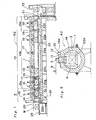
- the furnace K2 includes the furnace 1 which is separated into a charge chamber 3 and a heat treating chamber 15 by a partition door 2.
- the heat treating chamber 15 is further separated into a heating chamber 15a, a carburizing chamber 15b and a cooling chamber 15c by partition doors 2a and 2b.
- the furnace K2 further includes a hardening apparatus 23 following the cooling chamber 15c.
- the furnace K2 includes conveyor roller units 22a to 22f which are driven independently of one another for transporting the work W. Namely, the conveyor roller units 22a, 22b and 22f are provided in the charge chamber 3, the heating chamber 15a and the cooling chamber 15c, respectively.
- the carburizing chamber 15b is provided with three conveyor roller units, i.e., an inlet conveyor roller unit 22c, a central conveyor roller unit 22d and an outlet conveyor roller unit 22e.
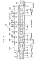
- the central roller unit 22d is further divided into a plurality of, for example, three roller segments 22d1, 22d2 and 22d3 as shown in Fig. 3. It is to be noted that the conveyor roller units 22a, 22b and 22f provided in the charge chamber 3, the heating chamber 15a and the cooling chamber 15c, respectively can be rotated not only forwardly but reversely so as to reciprocate the work W in the charge chamber 3, the heating chamber 15a and the cooling chamber 15c.
- the charge chamber 3 is provided with a heater 4 acting as an indirect heating means, a recirculating fan 5, an air supply pipe 9 for burning off cutting oil, etc. adhering to the work Wand a radiant tube 14.
- the radiant tube 14 is coupled, at one end thereof disposed outwardly of the furnace K2, with a discharge pipe 11 for discharging exhaust gas.
- the discharge pipe 11 is communicated with the charge chamber 3.
- the radiant tube 14 is provided, at its portion coupled with the discharge pipe 11, with a pilot burner 12 and an air inflow tube 14a for introducing combustion air into the radiant tube 14.
- a purge gas (a combustible gas in the heat treating chamber 15), which is drawn into the charge chamber 3 through a gap 3a between the partition door 2 and the inner face of the wall of the furnace 1, is exhausted from the furnace K2 by way of the discharge pipe 11 and the radiant tube 14.
- the gas purge means 6 is constituted by the gap 3a and the radiant tube 14.
- a combustion means 10 for burning the combustible gas is constituted by the air supply pipe 9, the air inflow tube 14a, the pilot burner 12, the charge chamber 3 and the radiant tube 14, with the charge chamber 3 and the radiant tube 14 acting as combustion chambers for the combustible gas.
- each of the heating chamber 15a, the carburizing chamber 15b and the cooling chamber 15c constituting the heat treating chamber 15 is provided with the heater 16, the recirculating fan 17 and a gas generator 18 for generating an endothermic gas that acts as a carrier gas.
- the furnace 1 is lined with refractories and the furnace K2 includes a plurality of driving devices for driving the conveyor roller units 22a to 22f, respectively. Accordingly, the conveyor roller units 22a to 22f are driven independently of one another by the driving devices so as to transport the work W in the furnace K2 at speeds shown in Fig. 3.
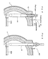
- Figs. 4 and 5 show constructions of the radiant tube 14 in detail.
- the purge gas is burnt in the radiant tube 14 upon ignition of the burner 12 connected, outwardly of the furnace 1, with the radiant tube 14 and upon introduction of air into the radiant tube 14from the air inflow tube 14a and the heat of combustion is utilized for heating in the charge chamber 3.
- the work W which has been cleaned through heating thereof and has been preheated in the charge chamber 3 is transferred from the charge chamber 3 to the heating chamber 15a upon opening of the partition door 2 and synchronous forward rotations of the conveyor roller units 22a and 22b.
- the partition door 2 is closed and the work W is heated substantially to a carburizing temperature while being reciprocated upon forward and reverse rotations of the conveyor roller unit 22b.
- the next work W is loaded into the charge chamber 3 such that preheating of the work W (cleaning of the work W thorugh vaporization of the cutting oil or the like) and purging of the charge chamber 3 are performed in the same manner as described above.
- the work W After heating of the work W in the heating chamber 15a, the work W is transferred from the heating chamber 15a to the carburizing chamber 15b upon opening of the partition door 2a and synchronous forward rotations of the conveyor roller unit 22b in the heating chamber 15a and the inlet conveyor roller unit 22c in the carburizing chamber 15b. Subsequently, the work W is sequentially transported towards the outlet conveyor roller unit 22e by the central conveyor roller unit 22d so as to be subjected to carburizing and diffusing in the carburizing chamber 15b. Then, the next work W is transferred from the charge chamber 3 to the heating chamber 15a upon closing of the partition door 2a, opening of the partition door 2 and synchronous forward rotations of the conveyor roller units 22a and 22b.
- the work W is cooled to a hardening temperature while being reciprocated upon forward and reverse rotations of the conveyor roller unit 22f. After the work W has been cooled to the hardening temperature, the work W is transferred from the cooling chamber 15c to the hardening apparatus 23 upon opening of the discharge door 21 and forward rotation of the conveyor roller unit 22f. After the work W has been subjected to hardening in the hardening apparatus 23, the work W is discharged out of the furnace K2.
- a furnace K2' which is a first modification of the furnace K2.
- the furnace K2' includes the partition doors 2 and 2b but is not provided with the partition door 2a.
- the heat treating chamber 15 of the furnace K2' is separated into the carburizing chamber 15b and the cooling chamber 15c by the partition doors 2 and 2b.
- the work W is heated to the carburizing temperature and is subjected to carburizing and diffusing while being maintained at the carburizing temperature. Then, the work W is maintained at the hardening temperature in the cooling chamber 15c.
- the central conveyor roller unit 22d of the carburizing chamber 15b is further divided into a plurality of roller segments.
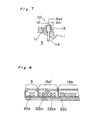
- Fig. 7 shows a combustion means 10' which is a modification of the combustion means 10 for burning the combustible gas in the charge chamber 3 of the furnaces K2 and K2'.
- the combustion means 10' for burning the combustible gas includes a combustion chamber 13 formed at one end portion of the radiant tube 14, which one end portion projects out of the furnace 1. Consequently, the vaporized cutting oil and the combustible gas which is produced at the time of purging of the charge chamber 3 and operation of the furnace K2 are subjected to complete combustion in the combustion chamber 13 by the pilot burner 12 and throughintroduction of combustion air into the combustion chamber 13 and then, are exhausted out of the furnace K2 via the radiant tube 14. 0
- Fig. 8 is a heating chamber 15a' which is a modification of the heating chamber 15a of the furnace K2.
- the conveyor roller unit 22b of the heating chamber 15a of the furnace K2 is divided into a plurality of, for example, two segments, i.e., conveyor roller units 22b1 and 22b2 driven independently of each other such that a plurality of, i.e., two works W in this case, are accommodated in the heating chamber 15a'.
- roller hearth type transport means is employed for transporting the work W in the above described embodiments of the present invention but can be replaced by any other transport means of tray pusher type, etc.
- the charge chamber provided with the heating means and the recirculating fan is employed in place of the prior art charge vestibule by separating the work loading side of the furnace by the use of the retractable partition door.
- the work can be preheated through convection in the charge chamber simultaneously with purging of the charge chamber, the work can be preheated uniformly and rapidly, thereby resulting in reduction of the heating time period of the work.
- the charge chamber is purged at high temperatures, amount of the purge gas consumed therefor can be reduced drastically. For example, it was found that when the charge chamber is set at a temperature of 800°C, a necessary amount of the purge gas is reduced to about 29% of that of the prior art charge vestibule held at ambient temperatures.
- the transport means of the continuous type atmosphere heat treating furnace is of roller hearth type and the furnace is a continuous type gas carburizing furnace, namely, the furnace is separated into the charge chamber, the heating chamber, the carburizing chamber and the cooling chamber or into the charge chamber, the carburizing chamber and the cooling chamber by the partition doors and the conveyor roller units driven independently of one another are, respectively, provided in the chambers such that the work is reciprocated during the heating process for heating the work to the carburizing temperature and the cooling process for cooling the work to the hardening temperature.
- the work is uniformly heated so as to prevent non-uniform carburizing of the work and is uniformly cooled with consequent elimination of non-uniform hardening of the work. Furthermore, since heating of the work to the carburizing temperature and cooling of the work to the hardening temperature can be performed rapidly, it becomes possible to reduce the length of the furnace.
- the central conveyor roller unit of the carburizing chamber is constituted by a plurality of the roller segments, vacant regions in the carburizing chamber can be reduced at the time of change of the carburizing conditions and thus, the carburizing conditions can be changed efficiency.
Landscapes
- Chemical & Material Sciences (AREA)
- Engineering & Computer Science (AREA)
- Organic Chemistry (AREA)
- Materials Engineering (AREA)
- Mechanical Engineering (AREA)
- Metallurgy (AREA)
- Physics & Mathematics (AREA)
- Thermal Sciences (AREA)
- Crystallography & Structural Chemistry (AREA)
- Chemical Kinetics & Catalysis (AREA)
- Tunnel Furnaces (AREA)
- Solid-Phase Diffusion Into Metallic Material Surfaces (AREA)
- Heat Treatments In General, Especially Conveying And Cooling (AREA)
Applications Claiming Priority (2)
| Application Number | Priority Date | Filing Date | Title |
|---|---|---|---|
| JP149130/84 | 1984-07-17 | ||
| JP14913084A JPS6127485A (ja) | 1984-07-17 | 1984-07-17 | 連続式雰囲気熱処理炉 |
Publications (3)
| Publication Number | Publication Date |
|---|---|
| EP0168788A2 EP0168788A2 (en) | 1986-01-22 |
| EP0168788A3 EP0168788A3 (en) | 1986-06-11 |
| EP0168788B1 true EP0168788B1 (en) | 1990-06-27 |
Family
ID=15468387
Family Applications (1)
| Application Number | Title | Priority Date | Filing Date |
|---|---|---|---|
| EP85108716A Expired - Lifetime EP0168788B1 (en) | 1984-07-17 | 1985-07-12 | Continuous type atmosphere heat treating furnace |
Country Status (5)
| Country | Link |
|---|---|
| US (1) | US4627814A (enExample) |
| EP (1) | EP0168788B1 (enExample) |
| JP (1) | JPS6127485A (enExample) |
| KR (1) | KR900003516B1 (enExample) |
| DE (1) | DE3578436D1 (enExample) |
Cited By (1)
| Publication number | Priority date | Publication date | Assignee | Title |
|---|---|---|---|---|
| WO2004050922A1 (ja) * | 2002-11-29 | 2004-06-17 | Dowa Mining Co., Ltd. | 熱処理方法及び熱処理炉 |
Families Citing this family (69)
| Publication number | Priority date | Publication date | Assignee | Title |
|---|---|---|---|---|
| WO1987003358A1 (fr) * | 1985-11-29 | 1987-06-04 | Riedhammer Gmbh Und Co. Kg | Procede et dispositif de traitement thermique de corps moules |
| EP0236666B1 (de) * | 1986-01-16 | 1991-09-11 | Sms Schloemann-Siemag Aktiengesellschaft | Arbeitsverfahren zum Aufheizen von in Stranggusseinrichtungen gegossenen oder in Umformeinrichtungen umgeformten Halbzeugen für deren Einbringen in Umform- und/oder Weiterverarbeitungseinrichtungen |
| US4950334A (en) * | 1986-08-12 | 1990-08-21 | Mitsubishi Jidosha Kogyo Kabushiki Kaisha | Gas carburizing method and apparatus |
| JP2590182B2 (ja) * | 1987-03-07 | 1997-03-12 | 株式会社東芝 | 黒化炉およびこの黒化炉を使用したシャドウマスクの製造方法 |
| DE3738136C1 (de) * | 1987-11-07 | 1989-01-26 | Heraeus Schott Quarzschmelze | Durchlaufofen zum Anloeten von elektronischen Bauteilen |
| DE3738527C1 (de) * | 1987-11-13 | 1988-06-09 | Lingl Anlagenbau | Umsetzbuehne fuer Tunnelofenbetrieb |
| JPH0714353Y2 (ja) * | 1988-07-08 | 1995-04-05 | 中外炉工業株式会社 | ローラハース型熱処理炉 |
| JP2742074B2 (ja) * | 1988-11-30 | 1998-04-22 | マツダ株式会社 | 浸炭炉 |
| JPH02201156A (ja) * | 1989-01-30 | 1990-08-09 | Dow Chem Nippon Kk | ガスクロマトグラフィー用熱分解装置 |
| JPH0739028B2 (ja) * | 1989-06-30 | 1995-05-01 | 松下電器産業株式会社 | 雰囲気炉 |
| JPH0791628B2 (ja) * | 1989-12-22 | 1995-10-04 | 大同ほくさん株式会社 | 窒化炉装置 |
| US5273585A (en) * | 1990-03-27 | 1993-12-28 | Mazda Motor Corporation | Heat-treating apparatus |
| DE4034653A1 (de) * | 1990-10-31 | 1992-05-07 | Loi Ind Ofenanlagen | Verfahren und durchstossofen zum waermebehandeln von werkstuecken |
| US5266027A (en) * | 1992-08-12 | 1993-11-30 | Ngk Insulators, Ltd. | Roller-hearth continuous furnace |
| DE4228006A1 (de) * | 1992-08-24 | 1994-03-03 | Ngk Insulators Ltd | Rollenherd-Durchlaufofen |
| ATE181971T1 (de) * | 1993-11-11 | 1999-07-15 | Daido Steel Co Ltd | Vorrichtung zur beseitigung von öl von aufwickelbare röhren |
| US5421723A (en) * | 1994-03-25 | 1995-06-06 | International Business Machines Corporation | Sequential step belt furnace with individual concentric cooling elements |
| JP3448789B2 (ja) * | 1995-01-20 | 2003-09-22 | 同和鉱業株式会社 | ガス浸炭方法 |
| US5577908A (en) * | 1995-04-24 | 1996-11-26 | General Thermal, Inc. | Apparatus for process for continuous curing |
| JP3484592B2 (ja) * | 1996-03-25 | 2004-01-06 | 光洋サーモシステム株式会社 | 熱処理装置 |
| IT1290102B1 (it) * | 1997-03-17 | 1998-10-19 | Siti | Forno per la cottura di materiali ceramici |
| US5868565A (en) * | 1997-06-17 | 1999-02-09 | Nowack; William C. | Method of heat treating articles and oven therefor |
| US5997286A (en) * | 1997-09-11 | 1999-12-07 | Ford Motor Company | Thermal treating apparatus and process |
| JP3783366B2 (ja) * | 1997-10-09 | 2006-06-07 | 松下電器産業株式会社 | 焼成炉 |
| SE9801260L (sv) * | 1998-04-07 | 1999-07-12 | Roland Niemi | Direkteldad ugn och sätt att återuppvärma stålämnen |
| US6217317B1 (en) * | 1998-12-15 | 2001-04-17 | Consolidated Engineering Company, Inc. | Combination conduction/convection furnace |
| US6336809B1 (en) * | 1998-12-15 | 2002-01-08 | Consolidated Engineering Company, Inc. | Combination conduction/convection furnace |
| AU768464B2 (en) * | 1999-03-02 | 2003-12-11 | Evraz Highveld Steel And Vanadium Limited | Endothermic heat treatment of solids loaded on trolleys moving in a kiln |
| US6283748B1 (en) | 1999-06-17 | 2001-09-04 | Btu International, Inc. | Continuous pusher furnace having traveling gas barrier |
| US6457971B2 (en) | 1999-06-17 | 2002-10-01 | Btu International, Inc. | Continuous furnace having traveling gas barrier |
| US7275582B2 (en) | 1999-07-29 | 2007-10-02 | Consolidated Engineering Company, Inc. | Methods and apparatus for heat treatment and sand removal for castings |
| EP1259772B1 (en) | 2000-02-02 | 2009-11-11 | BTU International, Inc. | Modular furnace system |
| US6622775B2 (en) | 2000-05-10 | 2003-09-23 | Consolidated Engineering Company, Inc. | Method and apparatus for assisting removal of sand moldings from castings |
| US6241515B1 (en) * | 2000-05-30 | 2001-06-05 | Tat Technologies, Inc | Device and method for treating combustibles obtained from a thermal processing apparatus and apparatus employed thereby |
| WO2002005986A2 (en) | 2000-07-17 | 2002-01-24 | Consolidated Engineering Company, Inc. | Method and apparatus for chill casting |
| US6328558B1 (en) * | 2000-08-04 | 2001-12-11 | Harper International Corp. | Purge chamber |
| TW500910B (en) * | 2000-10-10 | 2002-09-01 | Ishikawajima Harima Heavy Ind | Continuous sintering furnace and its using method |
| KR100442045B1 (ko) * | 2001-05-12 | 2004-07-30 | 조우석 | 자동식 광휘열처리로 |
| WO2003064949A1 (en) * | 2002-01-31 | 2003-08-07 | Jamar Venture Corporation | Counter-rotating tunnel furnace |
| JP4305716B2 (ja) * | 2002-02-12 | 2009-07-29 | Dowaホールディングス株式会社 | 熱処理炉 |
| AU2003248917B2 (en) | 2002-07-11 | 2007-04-19 | Consolidated Engineering Company, Inc. | Method and apparatus for assisting removal of sand moldings from castings |
| FR2863629B1 (fr) * | 2003-12-12 | 2006-12-08 | Etudes Const Mecaniques | Procede et dispositif de traitement physicochimique a chaud de pieces mecaniques |
| US6887074B1 (en) * | 2004-05-28 | 2005-05-03 | Teco Nanotech Co., Ltd. | Continuous production vacuum sintering apparatus and vacuum sintering system adopted to the same |
| JP4544537B2 (ja) * | 2004-08-23 | 2010-09-15 | 光洋サーモシステム株式会社 | 浸炭装置および浸炭方法 |
| US20060103059A1 (en) | 2004-10-29 | 2006-05-18 | Crafton Scott P | High pressure heat treatment system |
| CN100419096C (zh) * | 2006-05-08 | 2008-09-17 | 杭州金舟电炉有限公司 | 一种油电复合加热托辊网带炉 |
| CN100462448C (zh) * | 2006-06-14 | 2009-02-18 | 张洪民 | 一种轴承钢球化退火的方法及采用此方法的装置 |
| JP5116339B2 (ja) * | 2007-03-30 | 2013-01-09 | 光洋サーモシステム株式会社 | 連続浸炭炉 |
| US20100273121A1 (en) * | 2009-04-27 | 2010-10-28 | Gleason James M | Oven exhaust fan system and method |
| JP5167301B2 (ja) | 2010-03-29 | 2013-03-21 | トヨタ自動車株式会社 | 連続式ガス浸炭炉 |
| JP5830787B2 (ja) * | 2010-03-31 | 2015-12-09 | Dowaサーモテック株式会社 | 連続式熱処理炉 |
| JP5727313B2 (ja) * | 2011-07-04 | 2015-06-03 | 株式会社Ihi | 連続焼成炉 |
| CN103162300A (zh) * | 2011-12-15 | 2013-06-19 | 苏州瑞翔三禾科技有限公司 | 一种连续式传送污泥焚烧结块炉 |
| CN102620561A (zh) * | 2012-03-12 | 2012-08-01 | 苏州瑞翔三禾科技有限公司 | 燃气辐射管纵向安置的气电复合加热网带炉 |
| CN102620562A (zh) * | 2012-03-12 | 2012-08-01 | 苏州瑞翔三禾科技有限公司 | 一种托辊式气电复合加热网带炉 |
| US20150118012A1 (en) * | 2013-10-31 | 2015-04-30 | Lam Research Corporation | Wafer entry port with gas concentration attenuators |
| US9523136B2 (en) * | 2014-03-26 | 2016-12-20 | King Yuan Dar Metal Enterprise Co., Ltd. | Continuous furnace system |
| CN104531976A (zh) * | 2014-12-06 | 2015-04-22 | 苏州欣航微电子有限公司 | 一种电动自行车导轮热处理装置 |
| DE102015214711A1 (de) * | 2015-07-31 | 2017-02-02 | Dürr Systems Ag | Behandlungsanlage und Verfahren zum Behandeln von Werkstücken |
| DE102015214706A1 (de) | 2015-07-31 | 2017-02-02 | Dürr Systems Ag | Behandlungsanlage und Verfahren zum Behandeln von Werkstücken |
| CN204849000U (zh) * | 2015-09-01 | 2015-12-09 | 唐山亚捷机械有限公司 | 用于渗碳或碳氮共渗的加热炉 |
| CN105331790A (zh) * | 2015-11-06 | 2016-02-17 | 浙江尚鼎工业炉有限公司 | 一种连续式铝镁合金热处理炉 |
| KR101701328B1 (ko) * | 2016-01-22 | 2017-02-13 | 한국에너지기술연구원 | Rx 가스 발생기 내장형 무산화 열처리 설비 |
| CN106369995A (zh) * | 2016-08-31 | 2017-02-01 | 张家港康得新光电材料有限公司 | 隧道炉 |
| DE102018117355A1 (de) * | 2018-07-18 | 2020-01-23 | Eisenmann Se | Luftschleuse |
| CN110453058B (zh) * | 2019-08-09 | 2021-05-25 | 江苏良川科技发展有限公司 | 一种氨基气氛辊棒炉生产系统 |
| JP7399560B2 (ja) * | 2019-10-29 | 2023-12-18 | 株式会社ジェイテクトサーモシステム | 雰囲気置換装置及び熱処理システム |
| JP6974895B1 (ja) * | 2021-08-19 | 2021-12-01 | 関東冶金工業株式会社 | 熱処理炉 |
| CN115449610B (zh) * | 2022-09-27 | 2023-11-03 | 中冶南方(武汉)热工有限公司 | 一种明火加热和无氧化均热的热处理炉及热处理方法 |
Family Cites Families (13)
| Publication number | Priority date | Publication date | Assignee | Title |
|---|---|---|---|---|
| US802517A (en) * | 1904-04-30 | 1905-10-24 | Carl Kugel | Furnace for the continuous heating of metal objects without oxidation. |
| US2167676A (en) * | 1935-09-04 | 1939-08-01 | American Can Co | Mechanism for synchronizing tandem machines |
| US2205258A (en) * | 1939-11-15 | 1940-06-18 | Westinghouse Electric & Mfg Co | Protection for controlled atmosphere furnaces |
| DE863350C (de) * | 1943-02-23 | 1953-01-15 | Bergische Stahlindustrie | Ofen zum Gluehfrischen von Temperguss in Gas |
| US2713480A (en) * | 1950-08-14 | 1955-07-19 | Ruckstahl Alfred | Heat treating apparatus |
| US2955062A (en) * | 1952-02-27 | 1960-10-04 | Midland Ross Corp | Method for carburizing in a continuous furnace |
| GB776358A (en) * | 1954-05-18 | 1957-06-05 | Metallurg Oxygen Processes Ltd | An improved method for reheating steel |
| DE1236542B (de) * | 1962-05-02 | 1967-03-16 | Matthias Ludwig Industrieofenb | Ofen zum Gluehen von Gussstuecken |
| DE2254769C3 (de) * | 1972-11-09 | 1985-06-05 | Vereinigte Aluminium-Werke AG, 1000 Berlin und 5300 Bonn | Durchlaufofen zum flußmittellosen Löten von Aluminiumwerkstoffen unter Schutzgas |
| US3850318A (en) * | 1974-01-17 | 1974-11-26 | Sola Basic Ind Inc | Multiple tray pusher furnace |
| US4214869A (en) * | 1978-05-31 | 1980-07-29 | Midland-Ross Corporation | Furnace with radiant burndown tube |
| JPS5947006B2 (ja) * | 1981-03-23 | 1984-11-16 | 中外炉工業株式会社 | 前室を有する熱処理炉 |
| JPS585259A (ja) * | 1981-07-03 | 1983-01-12 | Toppan Printing Co Ltd | 印刷における見当判別方法 |
-
1984
- 1984-07-17 JP JP14913084A patent/JPS6127485A/ja active Granted
-
1985
- 1985-07-12 DE DE8585108716T patent/DE3578436D1/de not_active Expired - Lifetime
- 1985-07-12 EP EP85108716A patent/EP0168788B1/en not_active Expired - Lifetime
- 1985-07-15 KR KR1019850005031A patent/KR900003516B1/ko not_active Expired
- 1985-07-16 US US06/755,939 patent/US4627814A/en not_active Expired - Lifetime
Cited By (1)
| Publication number | Priority date | Publication date | Assignee | Title |
|---|---|---|---|---|
| WO2004050922A1 (ja) * | 2002-11-29 | 2004-06-17 | Dowa Mining Co., Ltd. | 熱処理方法及び熱処理炉 |
Also Published As
| Publication number | Publication date |
|---|---|
| KR900003516B1 (ko) | 1990-05-21 |
| EP0168788A3 (en) | 1986-06-11 |
| JPS6116910B2 (enExample) | 1986-05-02 |
| KR860001201A (ko) | 1986-02-24 |
| EP0168788A2 (en) | 1986-01-22 |
| US4627814A (en) | 1986-12-09 |
| JPS6127485A (ja) | 1986-02-06 |
| DE3578436D1 (de) | 1990-08-02 |
Similar Documents
| Publication | Publication Date | Title |
|---|---|---|
| EP0168788B1 (en) | Continuous type atmosphere heat treating furnace | |
| KR100338118B1 (ko) | 침탄,담금질및템퍼링방법및장치 | |
| EP0359756B1 (en) | Rotary hearth multi-chamber multi-purpose furnace system | |
| US4225121A (en) | Energy efficient heat-treating furnace system | |
| JPH06511514A (ja) | 金属工作物を熱処理する装置 | |
| RU2031184C1 (ru) | Способ химико-термической обработки длинномерных деталей и устройство для его осуществления | |
| KR950001215B1 (ko) | 가스 침탄방법 및 그의 장치 | |
| JPS6124981A (ja) | ロ−ラハ−ス型連続ガス浸炭炉 | |
| GB2045408A (en) | Furnace system | |
| JP3537049B2 (ja) | 連続真空浸炭方法およびその装置 | |
| US2497442A (en) | Means for heat-treating material | |
| GB2134548A (en) | Method for hardening metal workpieces | |
| JP2742074B2 (ja) | 浸炭炉 | |
| US2496914A (en) | Heating furnace | |
| JPS55107735A (en) | Batch annealing furnace operating method | |
| JPH0353557B2 (enExample) | ||
| JPS624464B2 (enExample) | ||
| JPS6235471B2 (enExample) | ||
| Sverdlin | Types of Heat Treating Furnaces | |
| SU1321757A1 (ru) | Проходна печь дл химико-термической обработки изделий | |
| US2817507A (en) | Forge furnace | |
| RU2138748C1 (ru) | Печь для комбинированного отжига порошка-сырца | |
| RU1788411C (ru) | Проходна печь | |
| SU949323A1 (ru) | Устройство дл подогрева шихты | |
| SU877288A1 (ru) | Проходна печь дл нагрева |
Legal Events
| Date | Code | Title | Description |
|---|---|---|---|
| PUAI | Public reference made under article 153(3) epc to a published international application that has entered the european phase |
Free format text: ORIGINAL CODE: 0009012 |
|
| AK | Designated contracting states |
Designated state(s): BE DE FR GB IT SE |
|
| PUAL | Search report despatched |
Free format text: ORIGINAL CODE: 0009013 |
|
| AK | Designated contracting states |
Kind code of ref document: A3 Designated state(s): BE DE FR GB IT SE |
|
| 17P | Request for examination filed |
Effective date: 19860725 |
|
| 17Q | First examination report despatched |
Effective date: 19870722 |
|
| RAP1 | Party data changed (applicant data changed or rights of an application transferred) |
Owner name: CHUGAI RO CO., LTD. |
|
| GRAA | (expected) grant |
Free format text: ORIGINAL CODE: 0009210 |
|
| AK | Designated contracting states |
Kind code of ref document: B1 Designated state(s): BE DE FR GB IT SE |
|
| ITF | It: translation for a ep patent filed | ||
| ET | Fr: translation filed | ||
| REF | Corresponds to: |
Ref document number: 3578436 Country of ref document: DE Date of ref document: 19900802 |
|
| PLBE | No opposition filed within time limit |
Free format text: ORIGINAL CODE: 0009261 |
|
| STAA | Information on the status of an ep patent application or granted ep patent |
Free format text: STATUS: NO OPPOSITION FILED WITHIN TIME LIMIT |
|
| 26N | No opposition filed | ||
| ITTA | It: last paid annual fee | ||
| EAL | Se: european patent in force in sweden |
Ref document number: 85108716.3 |
|
| PGFP | Annual fee paid to national office [announced via postgrant information from national office to epo] |
Ref country code: SE Payment date: 19970529 Year of fee payment: 13 |
|
| PGFP | Annual fee paid to national office [announced via postgrant information from national office to epo] |
Ref country code: BE Payment date: 19970612 Year of fee payment: 13 |
|
| PGFP | Annual fee paid to national office [announced via postgrant information from national office to epo] |
Ref country code: FR Payment date: 19970731 Year of fee payment: 13 |
|
| PG25 | Lapsed in a contracting state [announced via postgrant information from national office to epo] |
Ref country code: SE Free format text: LAPSE BECAUSE OF NON-PAYMENT OF DUE FEES Effective date: 19980713 |
|
| PG25 | Lapsed in a contracting state [announced via postgrant information from national office to epo] |
Ref country code: BE Free format text: LAPSE BECAUSE OF NON-PAYMENT OF DUE FEES Effective date: 19980731 |
|
| PGFP | Annual fee paid to national office [announced via postgrant information from national office to epo] |
Ref country code: DE Payment date: 19980923 Year of fee payment: 14 |
|
| BERE | Be: lapsed |
Owner name: CHUGAI RO CO. LTD Effective date: 19980731 |
|
| EUG | Se: european patent has lapsed |
Ref document number: 85108716.3 |
|
| PG25 | Lapsed in a contracting state [announced via postgrant information from national office to epo] |
Ref country code: FR Free format text: LAPSE BECAUSE OF NON-PAYMENT OF DUE FEES Effective date: 19990331 |
|
| REG | Reference to a national code |
Ref country code: FR Ref legal event code: ST |
|
| PG25 | Lapsed in a contracting state [announced via postgrant information from national office to epo] |
Ref country code: DE Free format text: LAPSE BECAUSE OF NON-PAYMENT OF DUE FEES Effective date: 20000503 |
|
| PGFP | Annual fee paid to national office [announced via postgrant information from national office to epo] |
Ref country code: GB Payment date: 20010711 Year of fee payment: 17 |
|
| REG | Reference to a national code |
Ref country code: GB Ref legal event code: IF02 |
|
| PG25 | Lapsed in a contracting state [announced via postgrant information from national office to epo] |
Ref country code: GB Free format text: LAPSE BECAUSE OF NON-PAYMENT OF DUE FEES Effective date: 20020712 |
|
| GBPC | Gb: european patent ceased through non-payment of renewal fee |
Effective date: 20020712 |