EP0168788B1 - Continuous type atmosphere heat treating furnace - Google Patents
Continuous type atmosphere heat treating furnace Download PDFInfo
- Publication number
- EP0168788B1 EP0168788B1 EP85108716A EP85108716A EP0168788B1 EP 0168788 B1 EP0168788 B1 EP 0168788B1 EP 85108716 A EP85108716 A EP 85108716A EP 85108716 A EP85108716 A EP 85108716A EP 0168788 B1 EP0168788 B1 EP 0168788B1
- Authority
- EP
- European Patent Office
- Prior art keywords
- chamber
- roller unit
- heat treating
- furnace
- charge
- Prior art date
- Legal status (The legal status is an assumption and is not a legal conclusion. Google has not performed a legal analysis and makes no representation as to the accuracy of the status listed.)
- Expired - Lifetime
Links
Images

Classifications
-
- C—CHEMISTRY; METALLURGY
- C21—METALLURGY OF IRON
- C21D—MODIFYING THE PHYSICAL STRUCTURE OF FERROUS METALS; GENERAL DEVICES FOR HEAT TREATMENT OF FERROUS OR NON-FERROUS METALS OR ALLOYS; MAKING METAL MALLEABLE, e.g. BY DECARBURISATION OR TEMPERING
- C21D1/00—General methods or devices for heat treatment, e.g. annealing, hardening, quenching or tempering
-
- C—CHEMISTRY; METALLURGY
- C23—COATING METALLIC MATERIAL; COATING MATERIAL WITH METALLIC MATERIAL; CHEMICAL SURFACE TREATMENT; DIFFUSION TREATMENT OF METALLIC MATERIAL; COATING BY VACUUM EVAPORATION, BY SPUTTERING, BY ION IMPLANTATION OR BY CHEMICAL VAPOUR DEPOSITION, IN GENERAL; INHIBITING CORROSION OF METALLIC MATERIAL OR INCRUSTATION IN GENERAL
- C23C—COATING METALLIC MATERIAL; COATING MATERIAL WITH METALLIC MATERIAL; SURFACE TREATMENT OF METALLIC MATERIAL BY DIFFUSION INTO THE SURFACE, BY CHEMICAL CONVERSION OR SUBSTITUTION; COATING BY VACUUM EVAPORATION, BY SPUTTERING, BY ION IMPLANTATION OR BY CHEMICAL VAPOUR DEPOSITION, IN GENERAL
- C23C8/00—Solid state diffusion of only non-metal elements into metallic material surfaces; Chemical surface treatment of metallic material by reaction of the surface with a reactive gas, leaving reaction products of surface material in the coating, e.g. conversion coatings, passivation of metals
- C23C8/06—Solid state diffusion of only non-metal elements into metallic material surfaces; Chemical surface treatment of metallic material by reaction of the surface with a reactive gas, leaving reaction products of surface material in the coating, e.g. conversion coatings, passivation of metals using gases
-
- C—CHEMISTRY; METALLURGY
- C21—METALLURGY OF IRON
- C21D—MODIFYING THE PHYSICAL STRUCTURE OF FERROUS METALS; GENERAL DEVICES FOR HEAT TREATMENT OF FERROUS OR NON-FERROUS METALS OR ALLOYS; MAKING METAL MALLEABLE, e.g. BY DECARBURISATION OR TEMPERING
- C21D1/00—General methods or devices for heat treatment, e.g. annealing, hardening, quenching or tempering
- C21D1/74—Methods of treatment in inert gas, controlled atmosphere, vacuum or pulverulent material
-
- C—CHEMISTRY; METALLURGY
- C21—METALLURGY OF IRON
- C21D—MODIFYING THE PHYSICAL STRUCTURE OF FERROUS METALS; GENERAL DEVICES FOR HEAT TREATMENT OF FERROUS OR NON-FERROUS METALS OR ALLOYS; MAKING METAL MALLEABLE, e.g. BY DECARBURISATION OR TEMPERING
- C21D9/00—Heat treatment, e.g. annealing, hardening, quenching or tempering, adapted for particular articles; Furnaces therefor
- C21D9/0062—Heat-treating apparatus with a cooling or quenching zone
Definitions
- the present invention relates to a continuous type heat treating furnace according to the preamble part of claim 1.
- a protective atmosphere suitable for heat treatment of ferrous metal works, for example, a carburizing gas, an endothermic gas, an exothermic gas, a mixture of the endothermic gas and the exothermic gas, etc. is drawn into the furnace such that the heat treatment is performed under the protective atmosphere.
- Continuous type atmosphere heat treating furnaces to be used for such heat treatment include a charge vestibule or a discharge vestibule designed for protecting atmosphere in the furnaces.
- the charge vestibule or the discharge vestibule which is of a steel structure, is provided with a proper purge means and is substantially maintained at ambient temperatures.
- the known furnaces have such a drawback that in the case where the charge or discharge vestibule is subjected to gas purging at the time of transfer of the works from the charge vestibule to a heat treating chamber or transfer of the works from the heat treating chamber to the discharge vestibule, a purge gas in an amount four to six times a capacity of the charge or discharge vestibule is required to be used, thereby making the gas purging uneconomical.
- the known furnaces have such a disadvantage that since the works are heated from ambient temperatures in the heat. treating chamber, the heat treating chamber itself is required to be made large in size, thus resulting in poor thermal efficiency of the heat treating chamber.
- the works are washed by using trichloroethylene (trichlene) or are cleaned through heating thereof prior to loading of the works into the furnaces in order to remove from the works impurities such as oil, etc. adhering thereto.
- trichloroethylene trichlene
- a continuous heat treating furnace according to the preamble part of claim 1 is disclosed in US ⁇ A ⁇ 2 713 480.
- the work pieces are preheated in a separate chamber by a separate heating tube and the chamber is provided with a fan which improve convectional heat transfer by agitation.
- a fan which improve convectional heat transfer by agitation.
- an essential object of the present invention is to provide a continuous type atmosphere heat treating furnace whose production cost is low and in which a purge gas required therefor is not only reduced in amount but effectively utilized, with substantial elimination of the disadvantages inherent in conventional heat treating furnaces of this kind.
- Another important object of the present invention is to provide an atmosphere heat treating furnace of the above described type in which a heating time period is reduced for the purpose of energy saving through utilization of heat of cutting oil, etc. adhering to works to be treated.
- the work can be cleaned through heating thereof in the charge chamber in the case where a combustible protective atmosphere for a gas-carburizing process, a non-oxidizing heating process, etc. is used in the continuous type gaseous atmosphere heat treating furnace.
- a combustible protective atmosphere for a gas-carburizing process, a non-oxidizing heating process, etc. is used in the continuous type gaseous atmosphere heat treating furnace.
- heat of combustion of the combustible gas at the time of cleaning of the work through heating thereof and the combustible gas in the heat treating chamber can be used as a part of the heat source of the charge chamber. Consequently, the heating time period of the work in the heating chamber can be reduced due to the effect of preheating of the work, thereby resulting in saving of energy.
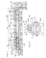
- the furnace K2 includes the furnace 1 which is separated into a charge chamber 3 and a heat treating chamber 15 by a partition door 2.
- the heat treating chamber 15 is further separated into a heating chamber 15a, a carburizing chamber 15b and a cooling chamber 15c by partition doors 2a and 2b.
- the furnace K2 further includes a hardening apparatus 23 following the cooling chamber 15c.
- the furnace K2 includes conveyor roller units 22a to 22f which are driven independently of one another for transporting the work W. Namely, the conveyor roller units 22a, 22b and 22f are provided in the charge chamber 3, the heating chamber 15a and the cooling chamber 15c, respectively.
- the carburizing chamber 15b is provided with three conveyor roller units, i.e., an inlet conveyor roller unit 22c, a central conveyor roller unit 22d and an outlet conveyor roller unit 22e.
- the central roller unit 22d is further divided into a plurality of, for example, three roller segments 22d1, 22d2 and 22d3 as shown in Fig. 3. It is to be noted that the conveyor roller units 22a, 22b and 22f provided in the charge chamber 3, the heating chamber 15a and the cooling chamber 15c, respectively can be rotated not only forwardly but reversely so as to reciprocate the work W in the charge chamber 3, the heating chamber 15a and the cooling chamber 15c.
- the charge chamber 3 is provided with a heater 4 acting as an indirect heating means, a recirculating fan 5, an air supply pipe 9 for burning off cutting oil, etc. adhering to the work Wand a radiant tube 14.
- the radiant tube 14 is coupled, at one end thereof disposed outwardly of the furnace K2, with a discharge pipe 11 for discharging exhaust gas.
- the discharge pipe 11 is communicated with the charge chamber 3.
- the radiant tube 14 is provided, at its portion coupled with the discharge pipe 11, with a pilot burner 12 and an air inflow tube 14a for introducing combustion air into the radiant tube 14.
- a purge gas (a combustible gas in the heat treating chamber 15), which is drawn into the charge chamber 3 through a gap 3a between the partition door 2 and the inner face of the wall of the furnace 1, is exhausted from the furnace K2 by way of the discharge pipe 11 and the radiant tube 14.
- the gas purge means 6 is constituted by the gap 3a and the radiant tube 14.
- a combustion means 10 for burning the combustible gas is constituted by the air supply pipe 9, the air inflow tube 14a, the pilot burner 12, the charge chamber 3 and the radiant tube 14, with the charge chamber 3 and the radiant tube 14 acting as combustion chambers for the combustible gas.
- each of the heating chamber 15a, the carburizing chamber 15b and the cooling chamber 15c constituting the heat treating chamber 15 is provided with the heater 16, the recirculating fan 17 and a gas generator 18 for generating an endothermic gas that acts as a carrier gas.
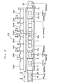
- the furnace 1 is lined with refractories and the furnace K2 includes a plurality of driving devices for driving the conveyor roller units 22a to 22f, respectively. Accordingly, the conveyor roller units 22a to 22f are driven independently of one another by the driving devices so as to transport the work W in the furnace K2 at speeds shown in Fig. 3.
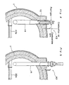
- Figs. 4 and 5 show constructions of the radiant tube 14 in detail.
- the purge gas is burnt in the radiant tube 14 upon ignition of the burner 12 connected, outwardly of the furnace 1, with the radiant tube 14 and upon introduction of air into the radiant tube 14from the air inflow tube 14a and the heat of combustion is utilized for heating in the charge chamber 3.
- the work W which has been cleaned through heating thereof and has been preheated in the charge chamber 3 is transferred from the charge chamber 3 to the heating chamber 15a upon opening of the partition door 2 and synchronous forward rotations of the conveyor roller units 22a and 22b.
- the partition door 2 is closed and the work W is heated substantially to a carburizing temperature while being reciprocated upon forward and reverse rotations of the conveyor roller unit 22b.
- the next work W is loaded into the charge chamber 3 such that preheating of the work W (cleaning of the work W thorugh vaporization of the cutting oil or the like) and purging of the charge chamber 3 are performed in the same manner as described above.
- the work W After heating of the work W in the heating chamber 15a, the work W is transferred from the heating chamber 15a to the carburizing chamber 15b upon opening of the partition door 2a and synchronous forward rotations of the conveyor roller unit 22b in the heating chamber 15a and the inlet conveyor roller unit 22c in the carburizing chamber 15b. Subsequently, the work W is sequentially transported towards the outlet conveyor roller unit 22e by the central conveyor roller unit 22d so as to be subjected to carburizing and diffusing in the carburizing chamber 15b. Then, the next work W is transferred from the charge chamber 3 to the heating chamber 15a upon closing of the partition door 2a, opening of the partition door 2 and synchronous forward rotations of the conveyor roller units 22a and 22b.
- the work W is cooled to a hardening temperature while being reciprocated upon forward and reverse rotations of the conveyor roller unit 22f. After the work W has been cooled to the hardening temperature, the work W is transferred from the cooling chamber 15c to the hardening apparatus 23 upon opening of the discharge door 21 and forward rotation of the conveyor roller unit 22f. After the work W has been subjected to hardening in the hardening apparatus 23, the work W is discharged out of the furnace K2.
- a furnace K2' which is a first modification of the furnace K2.
- the furnace K2' includes the partition doors 2 and 2b but is not provided with the partition door 2a.
- the heat treating chamber 15 of the furnace K2' is separated into the carburizing chamber 15b and the cooling chamber 15c by the partition doors 2 and 2b.
- the work W is heated to the carburizing temperature and is subjected to carburizing and diffusing while being maintained at the carburizing temperature. Then, the work W is maintained at the hardening temperature in the cooling chamber 15c.
- the central conveyor roller unit 22d of the carburizing chamber 15b is further divided into a plurality of roller segments.
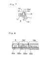
- Fig. 7 shows a combustion means 10' which is a modification of the combustion means 10 for burning the combustible gas in the charge chamber 3 of the furnaces K2 and K2'.
- the combustion means 10' for burning the combustible gas includes a combustion chamber 13 formed at one end portion of the radiant tube 14, which one end portion projects out of the furnace 1. Consequently, the vaporized cutting oil and the combustible gas which is produced at the time of purging of the charge chamber 3 and operation of the furnace K2 are subjected to complete combustion in the combustion chamber 13 by the pilot burner 12 and throughintroduction of combustion air into the combustion chamber 13 and then, are exhausted out of the furnace K2 via the radiant tube 14. 0
- Fig. 8 is a heating chamber 15a' which is a modification of the heating chamber 15a of the furnace K2.
- the conveyor roller unit 22b of the heating chamber 15a of the furnace K2 is divided into a plurality of, for example, two segments, i.e., conveyor roller units 22b1 and 22b2 driven independently of each other such that a plurality of, i.e., two works W in this case, are accommodated in the heating chamber 15a'.
- roller hearth type transport means is employed for transporting the work W in the above described embodiments of the present invention but can be replaced by any other transport means of tray pusher type, etc.
- the charge chamber provided with the heating means and the recirculating fan is employed in place of the prior art charge vestibule by separating the work loading side of the furnace by the use of the retractable partition door.
- the work can be preheated through convection in the charge chamber simultaneously with purging of the charge chamber, the work can be preheated uniformly and rapidly, thereby resulting in reduction of the heating time period of the work.
- the charge chamber is purged at high temperatures, amount of the purge gas consumed therefor can be reduced drastically. For example, it was found that when the charge chamber is set at a temperature of 800°C, a necessary amount of the purge gas is reduced to about 29% of that of the prior art charge vestibule held at ambient temperatures.
- the transport means of the continuous type atmosphere heat treating furnace is of roller hearth type and the furnace is a continuous type gas carburizing furnace, namely, the furnace is separated into the charge chamber, the heating chamber, the carburizing chamber and the cooling chamber or into the charge chamber, the carburizing chamber and the cooling chamber by the partition doors and the conveyor roller units driven independently of one another are, respectively, provided in the chambers such that the work is reciprocated during the heating process for heating the work to the carburizing temperature and the cooling process for cooling the work to the hardening temperature.
- the work is uniformly heated so as to prevent non-uniform carburizing of the work and is uniformly cooled with consequent elimination of non-uniform hardening of the work. Furthermore, since heating of the work to the carburizing temperature and cooling of the work to the hardening temperature can be performed rapidly, it becomes possible to reduce the length of the furnace.
- the central conveyor roller unit of the carburizing chamber is constituted by a plurality of the roller segments, vacant regions in the carburizing chamber can be reduced at the time of change of the carburizing conditions and thus, the carburizing conditions can be changed efficiency.
Description
- The present invention relates to a continuous type heat treating furnace according to the preamble part of
claim 1. - In heat treatment such as carburizing, carbo- nitriding, non-oxidizing hardening, bright annealing, etc., it has been conventionally so arranged that a protective atmosphere suitable for heat treatment of ferrous metal works, for example, a carburizing gas, an endothermic gas, an exothermic gas, a mixture of the endothermic gas and the exothermic gas, etc. is drawn into the furnace such that the heat treatment is performed under the protective atmosphere. Continuous type atmosphere heat treating furnaces to be used for such heat treatment include a charge vestibule or a discharge vestibule designed for protecting atmosphere in the furnaces. The charge vestibule or the discharge vestibule, which is of a steel structure, is provided with a proper purge means and is substantially maintained at ambient temperatures. Accordingly, the known furnaces have such a drawback that in the case where the charge or discharge vestibule is subjected to gas purging at the time of transfer of the works from the charge vestibule to a heat treating chamber or transfer of the works from the heat treating chamber to the discharge vestibule, a purge gas in an amount four to six times a capacity of the charge or discharge vestibule is required to be used, thereby making the gas purging uneconomical. Furthermore, the known furnaces have such a disadvantage that since the works are heated from ambient temperatures in the heat. treating chamber, the heat treating chamber itself is required to be made large in size, thus resulting in poor thermal efficiency of the heat treating chamber.
- Meanwhile, in the case of gas carburizing, non-oxidizing hardening, etc. in which a combustible protective atmosphere is introduced into the heat treating chamber during the heat treatment, it has been so arranged that the atmosphere in the heat treating chamber is supplied into the charge or discharge vestibule so as to subject the charge or discharge vestibule to gas purging. In this case, the purge gas (combustible gas) is exhausted from the furnaces and burned off in the environment outside the furnace and thus, is not effectively utilized. Moreover, in gas carburizing, non-oxidizing hardening, etc., the works are washed by using trichloroethylene (trichlene) or are cleaned through heating thereof prior to loading of the works into the furnaces in order to remove from the works impurities such as oil, etc. adhering thereto.
- A continuous heat treating furnace according to the preamble part of
claim 1 is disclosed in US―A―2 713 480. In this furnace the work pieces are preheated in a separate chamber by a separate heating tube and the chamber is provided with a fan which improve convectional heat transfer by agitation. Although by this means a relatively uniform heating can be achieved, it is to be noted that heating of the chamber by single heating tube is conducted relatively slow and has high energy consumption leading to high processing costs. - Accordingly, an essential object of the present invention is to provide a continuous type atmosphere heat treating furnace whose production cost is low and in which a purge gas required therefor is not only reduced in amount but effectively utilized, with substantial elimination of the disadvantages inherent in conventional heat treating furnaces of this kind.
- Another important object of the present invention is to provide an atmosphere heat treating furnace of the above described type in which a heating time period is reduced for the purpose of energy saving through utilization of heat of cutting oil, etc. adhering to works to be treated.
- These objects are achieved by a continuous heat treating furnace according to
claim 1. The dependent claims are related to further developments of the present invention. - In accordance with the present invention, since a combustion means for burning the combustible gas is provided in the charge chamber, the work can be cleaned through heating thereof in the charge chamber in the case where a combustible protective atmosphere for a gas-carburizing process, a non-oxidizing heating process, etc. is used in the continuous type gaseous atmosphere heat treating furnace. Thus, heating possessed by the work at the time of cleaning of the work through heating thereof can be effectively used. Furthermore, heat of combustion of the combustible gas at the time of cleaning of the work through heating thereof and the combustible gas in the heat treating chamber can be used as a part of the heat source of the charge chamber. Consequently, the heating time period of the work in the heating chamber can be reduced due to the effect of preheating of the work, thereby resulting in saving of energy.
- These objects and features of the present invention will become apparent from the following description taken in conjunction with the preferred embodiments thereof with reference to the accompanying drawings, in which:
- Fig. 1 is a schematic longitudinal sectional view of a continuous type atmosphere heat treating furnace according to an embodiment of the present invention;
- Fig. 2 is an enlarged cross-sectional view taken along the line IV-IV in Fig. 1;
- Fig. 3 is a schematic horizontal sectional view of the furnace of Fig. 1, particularly showing a plurality of driving devices for driving a plurality of roller units for conveying articles to be treated and transfer speeds of the articles driven by the driving devices;
- Figs. 4 and 5 are enlarged fragmentary cross-sectional views of the furnace of Fig. 1;
- Fig. 6 is a view similar to Fig. 1, particularly showing a first modification thereof;
- Fig. 7 is a fragmentary view similar to Fig. 2, particularly showing a combustion means which is a modification of that of the furnaces of Figs. 1 and 2; and
- Fig. 8 is a fragmentary view similar to Fig. 1, particularly showing a heating chamber which is a modification of that of the furnace of Fig. 1.
- Before the description of the present invention proceeds, it is to be noted that like parts are designated by like reference numerals throughout several views of the accompanying drawings.
- Referring to Figs. 1 to 5, there is shown a continuous type atmosphere heat treating furnace K2 according to an embodiment of the present invention. The furnace K2 includes the
furnace 1 which is separated into acharge chamber 3 and aheat treating chamber 15 by apartition door 2. Theheat treating chamber 15 is further separated into aheating chamber 15a, acarburizing chamber 15b and acooling chamber 15c bypartition doors apparatus 23 following thecooling chamber 15c. Meanwhile, the furnace K2 includesconveyor roller units 22a to 22f which are driven independently of one another for transporting the work W. Namely, theconveyor roller units charge chamber 3, theheating chamber 15a and thecooling chamber 15c, respectively. Thecarburizing chamber 15b is provided with three conveyor roller units, i.e., an inletconveyor roller unit 22c, a centralconveyor roller unit 22d and an outletconveyor roller unit 22e. Thecentral roller unit 22d is further divided into a plurality of, for example, three roller segments 22d1, 22d2 and 22d3 as shown in Fig. 3. It is to be noted that theconveyor roller units charge chamber 3, theheating chamber 15a and thecooling chamber 15c, respectively can be rotated not only forwardly but reversely so as to reciprocate the work W in thecharge chamber 3, theheating chamber 15a and thecooling chamber 15c. - Meanwhile, the
charge chamber 3 is provided with aheater 4 acting as an indirect heating means, arecirculating fan 5, anair supply pipe 9 for burning off cutting oil, etc. adhering to the work Wand aradiant tube 14. Theradiant tube 14 is coupled, at one end thereof disposed outwardly of the furnace K2, with adischarge pipe 11 for discharging exhaust gas. Thedischarge pipe 11 is communicated with thecharge chamber 3. Theradiant tube 14 is provided, at its portion coupled with thedischarge pipe 11, with apilot burner 12 and anair inflow tube 14a for introducing combustion air into theradiant tube 14. A purge gas, (a combustible gas in the heat treating chamber 15), which is drawn into thecharge chamber 3 through a gap 3a between thepartition door 2 and the inner face of the wall of thefurnace 1, is exhausted from the furnace K2 by way of thedischarge pipe 11 and theradiant tube 14. Namely, the gas purge means 6 is constituted by the gap 3a and theradiant tube 14. Meanwhile, a combustion means 10 for burning the combustible gas is constituted by theair supply pipe 9, theair inflow tube 14a, thepilot burner 12, thecharge chamber 3 and theradiant tube 14, with thecharge chamber 3 and theradiant tube 14 acting as combustion chambers for the combustible gas. Furthermore, each of theheating chamber 15a, thecarburizing chamber 15b and thecooling chamber 15c constituting theheat treating chamber 15 is provided with theheater 16, therecirculating fan 17 and agas generator 18 for generating an endothermic gas that acts as a carrier gas. - As shown in Fig. 3, the
furnace 1 is lined with refractories and the furnace K2 includes a plurality of driving devices for driving theconveyor roller units 22a to 22f, respectively. Accordingly, theconveyor roller units 22a to 22f are driven independently of one another by the driving devices so as to transport the work W in the furnace K2 at speeds shown in Fig. 3. Figs. 4 and 5 show constructions of theradiant tube 14 in detail. - Hereinbelow, a continuous gas carburizing process of the work W having cutting oil, etc. adhering thereto in the above described continuous type gaseous atmosphere heat treating furnace K2 of the roller hearth arrangement will be described. Initially, the temperature in the
charge chamber 3 is raised to a predetermined value, for example, about 800°C by theheater 4. Subsequently, upon opening of theloading door 20, the work W is loaded from the loading table 25 into thecharger chamber 3. The work W disposed in thecharge chamber 3 is reciprocated in thecharge chamber 3 upon forward and reverse rotations of theconveyor roller unit 22a and, at the same time, is preheated through convection by theheater 4 and therecirculating fan 5. During this time period, the cutting oil, etc. adhering to the work W are vaporized through heating thereof. In thecharge chamber 3, this vaporized oil is subjected to complete combustion together with the combustible gas supplied into thecharge chamber 3 by a predetermined amount of air introduced into thecharge chamber 3 from theair supply pipe 9. This combustion gas is exhausted out of the furnace K2 by way of thedischarge pipe 11 and theradiant tube 14. When the above described operation for vaporizing from the work W through heating thereof the cutting oil or the like adhering thereto has been completed, supply of air into thecharge chamber 3 from theair supply pipe 9 is stopped. Thereafter, thecharge chamber 3 is purged by using atmosphere (combustion gas) of theheat treating chamber 15 flowing into thecharge chamber 3 through the gap 3a between thepartition door 2 and the inner face of the wall of thefurnace 1. Before being exhausted from the furnace K2 by way of thedischarge pipe 11 and theradiant tube 14, the purge gas is burnt in theradiant tube 14 upon ignition of theburner 12 connected, outwardly of thefurnace 1, with theradiant tube 14 and upon introduction of air into the radiant tube 14from theair inflow tube 14a and the heat of combustion is utilized for heating in thecharge chamber 3. - When purging of the charge chamber has been completed, the work W, which has been cleaned through heating thereof and has been preheated in the
charge chamber 3, is transferred from thecharge chamber 3 to theheating chamber 15a upon opening of thepartition door 2 and synchronous forward rotations of theconveyor roller units charge chamber 3 to theheating chamber 15a, thepartition door 2 is closed and the work W is heated substantially to a carburizing temperature while being reciprocated upon forward and reverse rotations of theconveyor roller unit 22b. In the meantime, the next work W is loaded into thecharge chamber 3 such that preheating of the work W (cleaning of the work W thorugh vaporization of the cutting oil or the like) and purging of thecharge chamber 3 are performed in the same manner as described above. After heating of the work W in theheating chamber 15a, the work W is transferred from theheating chamber 15a to thecarburizing chamber 15b upon opening of thepartition door 2a and synchronous forward rotations of theconveyor roller unit 22b in theheating chamber 15a and the inletconveyor roller unit 22c in thecarburizing chamber 15b. Subsequently, the work W is sequentially transported towards the outletconveyor roller unit 22e by the centralconveyor roller unit 22d so as to be subjected to carburizing and diffusing in thecarburizing chamber 15b. Then, the next work W is transferred from thecharge chamber 3 to theheating chamber 15a upon closing of thepartition door 2a, opening of thepartition door 2 and synchronous forward rotations of theconveyor roller units - Thereafter, when the preceding work W transferred to the
carburizing chamber 15b has been displaced away from the inletconveyor roller unit 22c, the next work W in theheating chamber 15a is transported upon opening of thepartition door 2a and synchronous forward rotations of theconveyor roller units charge chamber 3, theheating chamber 15a and thecarburizing chamber 15b so as to be subjected to carburizing. When the foremost work W has reached the outletconveyor roller unit 22e of thecarburizing chamber 15b, the work W is transferred to thecooling chamber 15c upon opening of thepartition door 2b and synchronous forward rotations of theconveyor roller units cooling chamber 15c, the work W is cooled to a hardening temperature while being reciprocated upon forward and reverse rotations of theconveyor roller unit 22f. After the work W has been cooled to the hardening temperature, the work W is transferred from the coolingchamber 15c to the hardeningapparatus 23 upon opening of thedischarge door 21 and forward rotation of theconveyor roller unit 22f. After the work W has been subjected to hardening in the hardeningapparatus 23, the work W is discharged out of the furnace K2. - Referring further to Fig. 6, there is shown a furnace K2' which is a first modification of the furnace K2. The furnace K2' includes the
partition doors partition door 2a. Thus, theheat treating chamber 15 of the furnace K2' is separated into thecarburizing chamber 15b and thecooling chamber 15c by thepartition doors carburizing chamber 15b, the work W is heated to the carburizing temperature and is subjected to carburizing and diffusing while being maintained at the carburizing temperature. Then, the work W is maintained at the hardening temperature in thecooling chamber 15c. Since other constructions of the furnace K2'are substantially similarto those of the furnace K2, detailed description thereof is abbreviated for the sake of brevity. It can be, needless to say, also so arranged as shown in Fig. 3 that the centralconveyor roller unit 22d of thecarburizing chamber 15b is further divided into a plurality of roller segments. - Fig. 7 shows a combustion means 10' which is a modification of the combustion means 10 for burning the combustible gas in the
charge chamber 3 of the furnaces K2 and K2'. The combustion means 10' for burning the combustible gas includes acombustion chamber 13 formed at one end portion of theradiant tube 14, which one end portion projects out of thefurnace 1. Consequently, the vaporized cutting oil and the combustible gas which is produced at the time of purging of thecharge chamber 3 and operation of the furnace K2 are subjected to complete combustion in thecombustion chamber 13 by thepilot burner 12 and throughintroduction of combustion air into thecombustion chamber 13 and then, are exhausted out of the furnace K2 via theradiant tube 14. 0 - Meanwhile, Fig. 8 is a
heating chamber 15a' which is a modification of theheating chamber 15a of the furnace K2. In theheating chamber 15a', theconveyor roller unit 22b of theheating chamber 15a of the furnace K2 is divided into a plurality of, for example, two segments, i.e., conveyor roller units 22b1 and 22b2 driven independently of each other such that a plurality of, i.e., two works W in this case, are accommodated in theheating chamber 15a'. - It is to be noted that the roller hearth type transport means is employed for transporting the work W in the above described embodiments of the present invention but can be replaced by any other transport means of tray pusher type, etc.
- As is clear from the foregoing description, in the present invention, the charge chamber provided with the heating means and the recirculating fan is employed in place of the prior art charge vestibule by separating the work loading side of the furnace by the use of the retractable partition door.
- Accordingly, in accordance with the present invention, since the work can be preheated through convection in the charge chamber simultaneously with purging of the charge chamber, the work can be preheated uniformly and rapidly, thereby resulting in reduction of the heating time period of the work.
- Furthermore, in accordance with the present invention, since the charge chamber is purged at high temperatures, amount of the purge gas consumed therefor can be reduced drastically. For example, it was found that when the charge chamber is set at a temperature of 800°C, a necessary amount of the purge gas is reduced to about 29% of that of the prior art charge vestibule held at ambient temperatures.
- Meanwhile, in the present invention, it can be so arranged that the transport means of the continuous type atmosphere heat treating furnace is of roller hearth type and the furnace is a continuous type gas carburizing furnace, namely, the furnace is separated into the charge chamber, the heating chamber, the carburizing chamber and the cooling chamber or into the charge chamber, the carburizing chamber and the cooling chamber by the partition doors and the conveyor roller units driven independently of one another are, respectively, provided in the chambers such that the work is reciprocated during the heating process for heating the work to the carburizing temperature and the cooling process for cooling the work to the hardening temperature. Thus, in accordance with the present invention, the work is uniformly heated so as to prevent non-uniform carburizing of the work and is uniformly cooled with consequent elimination of non-uniform hardening of the work. Furthermore, since heating of the work to the carburizing temperature and cooling of the work to the hardening temperature can be performed rapidly, it becomes possible to reduce the length of the furnace.
- In addition, in accordance with the present invention, since the central conveyor roller unit of the carburizing chamber is constituted by a plurality of the roller segments, vacant regions in the carburizing chamber can be reduced at the time of change of the carburizing conditions and thus, the carburizing conditions can be changed efficiency.
Claims (11)
Applications Claiming Priority (2)
| Application Number | Priority Date | Filing Date | Title |
|---|---|---|---|
| JP14913084A JPS6127485A (en) | 1984-07-17 | 1984-07-17 | Continuous type atmosphere heat treatment furnace |
| JP149130/84 | 1984-07-17 |
Publications (3)
| Publication Number | Publication Date |
|---|---|
| EP0168788A2 EP0168788A2 (en) | 1986-01-22 |
| EP0168788A3 EP0168788A3 (en) | 1986-06-11 |
| EP0168788B1 true EP0168788B1 (en) | 1990-06-27 |
Family
ID=15468387
Family Applications (1)
| Application Number | Title | Priority Date | Filing Date |
|---|---|---|---|
| EP85108716A Expired - Lifetime EP0168788B1 (en) | 1984-07-17 | 1985-07-12 | Continuous type atmosphere heat treating furnace |
Country Status (5)
| Country | Link |
|---|---|
| US (1) | US4627814A (en) |
| EP (1) | EP0168788B1 (en) |
| JP (1) | JPS6127485A (en) |
| KR (1) | KR900003516B1 (en) |
| DE (1) | DE3578436D1 (en) |
Cited By (1)
| Publication number | Priority date | Publication date | Assignee | Title |
|---|---|---|---|---|
| WO2004050922A1 (en) * | 2002-11-29 | 2004-06-17 | Dowa Mining Co., Ltd. | Method and furnace for heat treatment |
Families Citing this family (67)
| Publication number | Priority date | Publication date | Assignee | Title |
|---|---|---|---|---|
| WO1987003358A1 (en) * | 1985-11-29 | 1987-06-04 | Riedhammer Gmbh Und Co. Kg | Device and process for the thermal treatment of formed bodies |
| ES2023824B3 (en) * | 1986-01-16 | 1992-02-16 | Sms Schloemann-Siemag Ag | WORKING PROCEDURE FOR HEATING OF SEMI-PRODUCTS POURED IN JET EQUIPMENT OR TRANSFORMED IN TRANSFORMATION EQUIPMENT FOR INTRODUCTION IN TRANSFORMATION AND / OR FURTHER TREATMENT EQUIPMENT. |
| US4950334A (en) * | 1986-08-12 | 1990-08-21 | Mitsubishi Jidosha Kogyo Kabushiki Kaisha | Gas carburizing method and apparatus |
| JP2590182B2 (en) * | 1987-03-07 | 1997-03-12 | 株式会社東芝 | Blackening furnace and method of manufacturing shadow mask using this blackening furnace |
| DE3738136C1 (en) * | 1987-11-07 | 1989-01-26 | Heraeus Schott Quarzschmelze | Continuous furnace for soldering electronic components |
| DE3738527C1 (en) * | 1987-11-13 | 1988-06-09 | Lingl Anlagenbau | Transfer platform for tunnel kiln operation |
| JPH0714353Y2 (en) * | 1988-07-08 | 1995-04-05 | 中外炉工業株式会社 | Roller hearth type heat treatment furnace |
| JP2742074B2 (en) * | 1988-11-30 | 1998-04-22 | マツダ株式会社 | Carburizing furnace |
| JPH02201156A (en) * | 1989-01-30 | 1990-08-09 | Dow Chem Nippon Kk | Pyrolysis apparatus for gas chromatography |
| JPH0739028B2 (en) * | 1989-06-30 | 1995-05-01 | 松下電器産業株式会社 | Atmosphere furnace |
| JPH0791628B2 (en) * | 1989-12-22 | 1995-10-04 | 大同ほくさん株式会社 | Nitriding furnace equipment |
| KR930007148B1 (en) * | 1990-03-27 | 1993-07-30 | 마쓰다 가부시끼가이샤 | Heat treating apparatus |
| DE4034653A1 (en) * | 1990-10-31 | 1992-05-07 | Loi Ind Ofenanlagen | Pusher-type furnace - divides row of containers into separate blocks at end of each push cycle for insertion of treatment zone dividing doors |
| US5266027A (en) * | 1992-08-12 | 1993-11-30 | Ngk Insulators, Ltd. | Roller-hearth continuous furnace |
| DE4228006A1 (en) * | 1992-08-24 | 1994-03-03 | Ngk Insulators Ltd | Continuous roller hearth furnace |
| ATE181971T1 (en) * | 1993-11-11 | 1999-07-15 | Daido Steel Co Ltd | DEVICE FOR REMOVING OIL FROM REWIND TUBES |
| US5421723A (en) * | 1994-03-25 | 1995-06-06 | International Business Machines Corporation | Sequential step belt furnace with individual concentric cooling elements |
| JP3448789B2 (en) * | 1995-01-20 | 2003-09-22 | 同和鉱業株式会社 | Gas carburizing method |
| US5577908A (en) * | 1995-04-24 | 1996-11-26 | General Thermal, Inc. | Apparatus for process for continuous curing |
| JP3484592B2 (en) * | 1996-03-25 | 2004-01-06 | 光洋サーモシステム株式会社 | Heat treatment equipment |
| IT1290102B1 (en) * | 1997-03-17 | 1998-10-19 | Siti | OVEN FOR COOKING CERAMIC MATERIALS |
| US5868565A (en) * | 1997-06-17 | 1999-02-09 | Nowack; William C. | Method of heat treating articles and oven therefor |
| US5997286A (en) * | 1997-09-11 | 1999-12-07 | Ford Motor Company | Thermal treating apparatus and process |
| JP3783366B2 (en) * | 1997-10-09 | 2006-06-07 | 松下電器産業株式会社 | Firing furnace |
| SE510931C2 (en) * | 1998-04-07 | 1999-07-12 | Roland Niemi | Direct-fired oven and ways to reheat steel materials |
| US6336809B1 (en) * | 1998-12-15 | 2002-01-08 | Consolidated Engineering Company, Inc. | Combination conduction/convection furnace |
| US6217317B1 (en) * | 1998-12-15 | 2001-04-17 | Consolidated Engineering Company, Inc. | Combination conduction/convection furnace |
| WO2000052215A1 (en) * | 1999-03-02 | 2000-09-08 | Csir | Endothermic heat treatment of solids loaded on trolleys moving in a kiln |
| US6283748B1 (en) | 1999-06-17 | 2001-09-04 | Btu International, Inc. | Continuous pusher furnace having traveling gas barrier |
| US6457971B2 (en) | 1999-06-17 | 2002-10-01 | Btu International, Inc. | Continuous furnace having traveling gas barrier |
| US7275582B2 (en) | 1999-07-29 | 2007-10-02 | Consolidated Engineering Company, Inc. | Methods and apparatus for heat treatment and sand removal for castings |
| US6394794B2 (en) | 2000-02-02 | 2002-05-28 | Btu International, Inc. | Modular furnace system |
| US6622775B2 (en) | 2000-05-10 | 2003-09-23 | Consolidated Engineering Company, Inc. | Method and apparatus for assisting removal of sand moldings from castings |
| US6241515B1 (en) * | 2000-05-30 | 2001-06-05 | Tat Technologies, Inc | Device and method for treating combustibles obtained from a thermal processing apparatus and apparatus employed thereby |
| WO2002005986A2 (en) | 2000-07-17 | 2002-01-24 | Consolidated Engineering Company, Inc. | Method and apparatus for chill casting |
| US6328558B1 (en) * | 2000-08-04 | 2001-12-11 | Harper International Corp. | Purge chamber |
| TW500910B (en) * | 2000-10-10 | 2002-09-01 | Ishikawajima Harima Heavy Ind | Continuous sintering furnace and its using method |
| KR100442045B1 (en) * | 2001-05-12 | 2004-07-30 | 조우석 | Automatic Bright heat treatment furnace |
| WO2003064949A1 (en) * | 2002-01-31 | 2003-08-07 | Jamar Venture Corporation | Counter-rotating tunnel furnace |
| JP4305716B2 (en) * | 2002-02-12 | 2009-07-29 | Dowaホールディングス株式会社 | Heat treatment furnace |
| JP2005532911A (en) | 2002-07-11 | 2005-11-04 | コンソリデイテッド エンジニアリング カンパニー, インコーポレイテッド | Method and apparatus for assisting removal of sand mold from castings |
| FR2863629B1 (en) * | 2003-12-12 | 2006-12-08 | Etudes Const Mecaniques | METHOD AND DEVICE FOR CHEMICAL CHEMICAL PROCESSING OF MECHANICAL PARTS |
| US6887074B1 (en) * | 2004-05-28 | 2005-05-03 | Teco Nanotech Co., Ltd. | Continuous production vacuum sintering apparatus and vacuum sintering system adopted to the same |
| DE112004002944T5 (en) * | 2004-08-23 | 2007-08-02 | Koyo Thermo Systems Co., Ltd., Tenri | Carburizing device and carburizing process |
| US20060103059A1 (en) | 2004-10-29 | 2006-05-18 | Crafton Scott P | High pressure heat treatment system |
| CN100419096C (en) * | 2006-05-08 | 2008-09-17 | 杭州金舟电炉有限公司 | Netted belt furnace for heating roller with both oil and electricity |
| CN100462448C (en) * | 2006-06-14 | 2009-02-18 | 张洪民 | Method of bearing ball annealing and device using the method |
| JP5116339B2 (en) * | 2007-03-30 | 2013-01-09 | 光洋サーモシステム株式会社 | Continuous carburizing furnace |
| US20100273121A1 (en) * | 2009-04-27 | 2010-10-28 | Gleason James M | Oven exhaust fan system and method |
| JP5167301B2 (en) | 2010-03-29 | 2013-03-21 | トヨタ自動車株式会社 | Continuous gas carburizing furnace |
| JP5830787B2 (en) * | 2010-03-31 | 2015-12-09 | Dowaサーモテック株式会社 | Continuous heat treatment furnace |
| JP5727313B2 (en) * | 2011-07-04 | 2015-06-03 | 株式会社Ihi | Continuous firing furnace |
| CN103162300A (en) * | 2011-12-15 | 2013-06-19 | 苏州瑞翔三禾科技有限公司 | Continuous type transmission sludge burning caking furnace |
| CN102620561A (en) * | 2012-03-12 | 2012-08-01 | 苏州瑞翔三禾科技有限公司 | Gas-electric compound heating mesh belt furnace with gas radiation pipes in vertical arrangement |
| CN102620562A (en) * | 2012-03-12 | 2012-08-01 | 苏州瑞翔三禾科技有限公司 | Carrier roller type gas-electric compound heating mesh belt furnace |
| US20150118012A1 (en) * | 2013-10-31 | 2015-04-30 | Lam Research Corporation | Wafer entry port with gas concentration attenuators |
| US9523136B2 (en) * | 2014-03-26 | 2016-12-20 | King Yuan Dar Metal Enterprise Co., Ltd. | Continuous furnace system |
| CN104531976A (en) * | 2014-12-06 | 2015-04-22 | 苏州欣航微电子有限公司 | Electric bicycle guide wheel heat treatment device |
| DE102015214711A1 (en) * | 2015-07-31 | 2017-02-02 | Dürr Systems Ag | Treatment plant and method for treating workpieces |
| DE102015214706A1 (en) | 2015-07-31 | 2017-02-02 | Dürr Systems Ag | Treatment plant and method for treating workpieces |
| CN204849000U (en) * | 2015-09-01 | 2015-12-09 | 唐山亚捷机械有限公司 | A heating furnace for carburization or carbonitriding |
| CN105331790A (en) * | 2015-11-06 | 2016-02-17 | 浙江尚鼎工业炉有限公司 | Continuous aluminum magnesium alloy thermal treatment furnace |
| KR101701328B1 (en) * | 2016-01-22 | 2017-02-13 | 한국에너지기술연구원 | Non Oxygen Annealing Furnace System with internal Rx generator |
| CN106369995A (en) * | 2016-08-31 | 2017-02-01 | 张家港康得新光电材料有限公司 | Tunnel kiln |
| DE102018117355A1 (en) * | 2018-07-18 | 2020-01-23 | Eisenmann Se | airlock |
| CN110453058B (en) * | 2019-08-09 | 2021-05-25 | 江苏良川科技发展有限公司 | Amino atmosphere roller stove production system |
| CN115449610B (en) * | 2022-09-27 | 2023-11-03 | 中冶南方(武汉)热工有限公司 | Heat treatment furnace for open fire heating and non-oxidation soaking and heat treatment method |
Family Cites Families (15)
| Publication number | Priority date | Publication date | Assignee | Title |
|---|---|---|---|---|
| US802517A (en) * | 1904-04-30 | 1905-10-24 | Carl Kugel | Furnace for the continuous heating of metal objects without oxidation. |
| US2167676A (en) * | 1935-09-04 | 1939-08-01 | American Can Co | Mechanism for synchronizing tandem machines |
| US2205258A (en) * | 1939-11-15 | 1940-06-18 | Westinghouse Electric & Mfg Co | Protection for controlled atmosphere furnaces |
| DE863350C (en) * | 1943-02-23 | 1953-01-15 | Bergische Stahlindustrie | Furnace for annealing malleable iron in gas |
| US2713480A (en) * | 1950-08-14 | 1955-07-19 | Ruckstahl Alfred | Heat treating apparatus |
| US2955062A (en) * | 1952-02-27 | 1960-10-04 | Midland Ross Corp | Method for carburizing in a continuous furnace |
| GB776358A (en) * | 1954-05-18 | 1957-06-05 | Metallurg Oxygen Processes Ltd | An improved method for reheating steel |
| DE1236542B (en) * | 1962-05-02 | 1967-03-16 | Matthias Ludwig Industrieofenb | Furnace for annealing castings |
| DE2254769C3 (en) * | 1972-11-09 | 1985-06-05 | Vereinigte Aluminium-Werke AG, 1000 Berlin und 5300 Bonn | Continuous furnace for flux-free soldering of aluminum materials under protective gas |
| US3850318A (en) * | 1974-01-17 | 1974-11-26 | Sola Basic Ind Inc | Multiple tray pusher furnace |
| JPS5299910A (en) * | 1976-02-17 | 1977-08-22 | Nippon Kokan Kk <Nkk> | Process and apparatus for annealing metallic coil |
| US4214869A (en) * | 1978-05-31 | 1980-07-29 | Midland-Ross Corporation | Furnace with radiant burndown tube |
| JPS582588B2 (en) * | 1978-12-29 | 1983-01-17 | 日産自動車株式会社 | Gas carburizing pretreatment method and equipment |
| JPS5947006B2 (en) * | 1981-03-23 | 1984-11-16 | 中外炉工業株式会社 | Heat treatment furnace with front chamber |
| JPS585259A (en) * | 1981-07-03 | 1983-01-12 | Toppan Printing Co Ltd | Registering method in printing |
-
1984
- 1984-07-17 JP JP14913084A patent/JPS6127485A/en active Granted
-
1985
- 1985-07-12 EP EP85108716A patent/EP0168788B1/en not_active Expired - Lifetime
- 1985-07-12 DE DE8585108716T patent/DE3578436D1/en not_active Expired - Lifetime
- 1985-07-15 KR KR1019850005031A patent/KR900003516B1/en not_active IP Right Cessation
- 1985-07-16 US US06/755,939 patent/US4627814A/en not_active Expired - Lifetime
Cited By (1)
| Publication number | Priority date | Publication date | Assignee | Title |
|---|---|---|---|---|
| WO2004050922A1 (en) * | 2002-11-29 | 2004-06-17 | Dowa Mining Co., Ltd. | Method and furnace for heat treatment |
Also Published As
| Publication number | Publication date |
|---|---|
| JPS6116910B2 (en) | 1986-05-02 |
| KR860001201A (en) | 1986-02-24 |
| EP0168788A2 (en) | 1986-01-22 |
| DE3578436D1 (en) | 1990-08-02 |
| JPS6127485A (en) | 1986-02-06 |
| EP0168788A3 (en) | 1986-06-11 |
| US4627814A (en) | 1986-12-09 |
| KR900003516B1 (en) | 1990-05-21 |
Similar Documents
| Publication | Publication Date | Title |
|---|---|---|
| EP0168788B1 (en) | Continuous type atmosphere heat treating furnace | |
| US5997286A (en) | Thermal treating apparatus and process | |
| EP0359756B1 (en) | Rotary hearth multi-chamber multi-purpose furnace system | |
| US4225121A (en) | Energy efficient heat-treating furnace system | |
| JPH06511514A (en) | Equipment for heat treating metal workpieces | |
| KR950001215B1 (en) | Gas-caburizing process and apparatus | |
| JPS6124981A (en) | Roller hearth type continuous gas carburizing furnace | |
| JP3537049B2 (en) | Continuous vacuum carburizing method and apparatus | |
| JPH10212565A (en) | Nitriding treatment and device used therefor | |
| US2497442A (en) | Means for heat-treating material | |
| GB2045408A (en) | Furnace system | |
| GB2134548A (en) | Method for hardening metal workpieces | |
| JP2742074B2 (en) | Carburizing furnace | |
| US2496914A (en) | Heating furnace | |
| JPS55107735A (en) | Batch annealing furnace operating method | |
| JPH0353557B2 (en) | ||
| RU2031184C1 (en) | Method for chemical-heat treatment of long-size parts and device for its realization | |
| JPS624464B2 (en) | ||
| JPS6235471B2 (en) | ||
| SU1321757A1 (en) | Continuous furnace for chemical and heat treatment of articles | |
| US2817507A (en) | Forge furnace | |
| RU2138748C1 (en) | Furnace for combined annealing of raw powder | |
| Sverdlin | Types of Heat Treating Furnaces | |
| SU1223000A1 (en) | Continuous muffle furnace | |
| SU949323A1 (en) | Device for heating up charge |
Legal Events
| Date | Code | Title | Description |
|---|---|---|---|
| PUAI | Public reference made under article 153(3) epc to a published international application that has entered the european phase |
Free format text: ORIGINAL CODE: 0009012 |
|
| AK | Designated contracting states |
Designated state(s): BE DE FR GB IT SE |
|
| PUAL | Search report despatched |
Free format text: ORIGINAL CODE: 0009013 |
|
| AK | Designated contracting states |
Kind code of ref document: A3 Designated state(s): BE DE FR GB IT SE |
|
| 17P | Request for examination filed |
Effective date: 19860725 |
|
| 17Q | First examination report despatched |
Effective date: 19870722 |
|
| RAP1 | Party data changed (applicant data changed or rights of an application transferred) |
Owner name: CHUGAI RO CO., LTD. |
|
| GRAA | (expected) grant |
Free format text: ORIGINAL CODE: 0009210 |
|
| AK | Designated contracting states |
Kind code of ref document: B1 Designated state(s): BE DE FR GB IT SE |
|
| ITF | It: translation for a ep patent filed |
Owner name: INTERPATENT ST TECN BREV. |
|
| ET | Fr: translation filed | ||
| REF | Corresponds to: |
Ref document number: 3578436 Country of ref document: DE Date of ref document: 19900802 |
|
| PLBE | No opposition filed within time limit |
Free format text: ORIGINAL CODE: 0009261 |
|
| STAA | Information on the status of an ep patent application or granted ep patent |
Free format text: STATUS: NO OPPOSITION FILED WITHIN TIME LIMIT |
|
| 26N | No opposition filed | ||
| ITTA | It: last paid annual fee | ||
| EAL | Se: european patent in force in sweden |
Ref document number: 85108716.3 |
|
| PGFP | Annual fee paid to national office [announced via postgrant information from national office to epo] |
Ref country code: SE Payment date: 19970529 Year of fee payment: 13 |
|
| PGFP | Annual fee paid to national office [announced via postgrant information from national office to epo] |
Ref country code: BE Payment date: 19970612 Year of fee payment: 13 |
|
| PGFP | Annual fee paid to national office [announced via postgrant information from national office to epo] |
Ref country code: FR Payment date: 19970731 Year of fee payment: 13 |
|
| PG25 | Lapsed in a contracting state [announced via postgrant information from national office to epo] |
Ref country code: SE Free format text: LAPSE BECAUSE OF NON-PAYMENT OF DUE FEES Effective date: 19980713 |
|
| PG25 | Lapsed in a contracting state [announced via postgrant information from national office to epo] |
Ref country code: BE Free format text: LAPSE BECAUSE OF NON-PAYMENT OF DUE FEES Effective date: 19980731 |
|
| PGFP | Annual fee paid to national office [announced via postgrant information from national office to epo] |
Ref country code: DE Payment date: 19980923 Year of fee payment: 14 |
|
| BERE | Be: lapsed |
Owner name: CHUGAI RO CO. LTD Effective date: 19980731 |
|
| EUG | Se: european patent has lapsed |
Ref document number: 85108716.3 |
|
| PG25 | Lapsed in a contracting state [announced via postgrant information from national office to epo] |
Ref country code: FR Free format text: LAPSE BECAUSE OF NON-PAYMENT OF DUE FEES Effective date: 19990331 |
|
| REG | Reference to a national code |
Ref country code: FR Ref legal event code: ST |
|
| PG25 | Lapsed in a contracting state [announced via postgrant information from national office to epo] |
Ref country code: DE Free format text: LAPSE BECAUSE OF NON-PAYMENT OF DUE FEES Effective date: 20000503 |
|
| PGFP | Annual fee paid to national office [announced via postgrant information from national office to epo] |
Ref country code: GB Payment date: 20010711 Year of fee payment: 17 |
|
| REG | Reference to a national code |
Ref country code: GB Ref legal event code: IF02 |
|
| PG25 | Lapsed in a contracting state [announced via postgrant information from national office to epo] |
Ref country code: GB Free format text: LAPSE BECAUSE OF NON-PAYMENT OF DUE FEES Effective date: 20020712 |
|
| GBPC | Gb: european patent ceased through non-payment of renewal fee |
Effective date: 20020712 |