EP0117545A2 - Catalyseur de craquage catalytique fluidisé comprenant des microsphères contenant plus que 40% en poids de faujasite Y et méthode pour sa préparation et son emploi - Google Patents
Catalyseur de craquage catalytique fluidisé comprenant des microsphères contenant plus que 40% en poids de faujasite Y et méthode pour sa préparation et son emploi Download PDFInfo
- Publication number
- EP0117545A2 EP0117545A2 EP84101946A EP84101946A EP0117545A2 EP 0117545 A2 EP0117545 A2 EP 0117545A2 EP 84101946 A EP84101946 A EP 84101946A EP 84101946 A EP84101946 A EP 84101946A EP 0117545 A2 EP0117545 A2 EP 0117545A2
- Authority
- EP
- European Patent Office
- Prior art keywords
- microspheres
- weight
- calcined
- catalyst
- clay
- Prior art date
- Legal status (The legal status is an assumption and is not a legal conclusion. Google has not performed a legal analysis and makes no representation as to the accuracy of the status listed.)
- Granted
Links
- 239000004005 microsphere Substances 0.000 title claims abstract description 470
- 239000003054 catalyst Substances 0.000 title claims abstract description 224
- 238000000034 method Methods 0.000 title claims abstract description 164
- 239000012013 faujasite Substances 0.000 title claims abstract description 47
- 238000004231 fluid catalytic cracking Methods 0.000 title claims abstract description 45
- 230000000694 effects Effects 0.000 claims abstract description 106
- 239000010457 zeolite Substances 0.000 claims abstract description 90
- HNPSIPDUKPIQMN-UHFFFAOYSA-N dioxosilane;oxo(oxoalumanyloxy)alumane Chemical compound O=[Si]=O.O=[Al]O[Al]=O HNPSIPDUKPIQMN-UHFFFAOYSA-N 0.000 claims abstract description 89
- 229910021536 Zeolite Inorganic materials 0.000 claims abstract description 88
- 239000003208 petroleum Substances 0.000 claims abstract description 12
- 239000004927 clay Substances 0.000 claims description 160
- 239000000243 solution Substances 0.000 claims description 140
- NLYAJNPCOHFWQQ-UHFFFAOYSA-N kaolin Chemical compound O.O.O=[Al]O[Si](=O)O[Si](=O)O[Al]=O NLYAJNPCOHFWQQ-UHFFFAOYSA-N 0.000 claims description 119
- 239000002002 slurry Substances 0.000 claims description 107
- VYPSYNLAJGMNEJ-UHFFFAOYSA-N Silicium dioxide Chemical compound O=[Si]=O VYPSYNLAJGMNEJ-UHFFFAOYSA-N 0.000 claims description 93
- 229910001868 water Inorganic materials 0.000 claims description 81
- 239000005995 Aluminium silicate Substances 0.000 claims description 75
- 235000012211 aluminium silicate Nutrition 0.000 claims description 75
- PXHVJJICTQNCMI-UHFFFAOYSA-N Nickel Chemical compound [Ni] PXHVJJICTQNCMI-UHFFFAOYSA-N 0.000 claims description 70
- 238000002425 crystallisation Methods 0.000 claims description 60
- 230000008025 crystallization Effects 0.000 claims description 60
- NTHWMYGWWRZVTN-UHFFFAOYSA-N sodium silicate Chemical compound [Na+].[Na+].[O-][Si]([O-])=O NTHWMYGWWRZVTN-UHFFFAOYSA-N 0.000 claims description 59
- 239000000203 mixture Substances 0.000 claims description 58
- 239000004115 Sodium Silicate Substances 0.000 claims description 57
- 229910052911 sodium silicate Inorganic materials 0.000 claims description 57
- 230000008569 process Effects 0.000 claims description 48
- -1 sodium cations Chemical class 0.000 claims description 46
- 239000003999 initiator Substances 0.000 claims description 45
- KKCBUQHMOMHUOY-UHFFFAOYSA-N Na2O Inorganic materials [O-2].[Na+].[Na+] KKCBUQHMOMHUOY-UHFFFAOYSA-N 0.000 claims description 44
- 239000000571 coke Substances 0.000 claims description 44
- 239000011148 porous material Substances 0.000 claims description 42
- 239000000377 silicon dioxide Substances 0.000 claims description 40
- 229910052739 hydrogen Inorganic materials 0.000 claims description 39
- 239000001257 hydrogen Substances 0.000 claims description 39
- 239000012452 mother liquor Substances 0.000 claims description 39
- 229910052761 rare earth metal Inorganic materials 0.000 claims description 39
- UFHFLCQGNIYNRP-UHFFFAOYSA-N Hydrogen Chemical compound [H][H] UFHFLCQGNIYNRP-UHFFFAOYSA-N 0.000 claims description 38
- 229910052681 coesite Inorganic materials 0.000 claims description 38
- 229910052906 cristobalite Inorganic materials 0.000 claims description 38
- 229910052682 stishovite Inorganic materials 0.000 claims description 38
- 229910052905 tridymite Inorganic materials 0.000 claims description 38
- 229910052720 vanadium Inorganic materials 0.000 claims description 36
- 229910052759 nickel Inorganic materials 0.000 claims description 35
- 238000006243 chemical reaction Methods 0.000 claims description 33
- LEONUFNNVUYDNQ-UHFFFAOYSA-N vanadium atom Chemical compound [V] LEONUFNNVUYDNQ-UHFFFAOYSA-N 0.000 claims description 33
- 238000002156 mixing Methods 0.000 claims description 31
- PNEYBMLMFCGWSK-UHFFFAOYSA-N aluminium oxide Inorganic materials [O-2].[O-2].[O-2].[Al+3].[Al+3] PNEYBMLMFCGWSK-UHFFFAOYSA-N 0.000 claims description 26
- XLYOFNOQVPJJNP-UHFFFAOYSA-N water Substances O XLYOFNOQVPJJNP-UHFFFAOYSA-N 0.000 claims description 25
- 238000001354 calcination Methods 0.000 claims description 24
- 229910052593 corundum Inorganic materials 0.000 claims description 24
- 229910001845 yogo sapphire Inorganic materials 0.000 claims description 24
- 239000000047 product Substances 0.000 claims description 17
- KZHJGOXRZJKJNY-UHFFFAOYSA-N dioxosilane;oxo(oxoalumanyloxy)alumane Chemical compound O=[Si]=O.O=[Si]=O.O=[Al]O[Al]=O.O=[Al]O[Al]=O.O=[Al]O[Al]=O KZHJGOXRZJKJNY-UHFFFAOYSA-N 0.000 claims description 16
- 229910052863 mullite Inorganic materials 0.000 claims description 16
- DGAQECJNVWCQMB-PUAWFVPOSA-M Ilexoside XXIX Chemical group C[C@@H]1CC[C@@]2(CC[C@@]3(C(=CC[C@H]4[C@]3(CC[C@@H]5[C@@]4(CC[C@@H](C5(C)C)OS(=O)(=O)[O-])C)C)[C@@H]2[C@]1(C)O)C)C(=O)O[C@H]6[C@@H]([C@H]([C@@H]([C@H](O6)CO)O)O)O.[Na+] DGAQECJNVWCQMB-PUAWFVPOSA-M 0.000 claims description 15
- 238000005336 cracking Methods 0.000 claims description 13
- QGZKDVFQNNGYKY-UHFFFAOYSA-O Ammonium Chemical compound [NH4+] QGZKDVFQNNGYKY-UHFFFAOYSA-O 0.000 claims description 11
- 238000010438 heat treatment Methods 0.000 claims description 11
- 238000001694 spray drying Methods 0.000 claims description 10
- 239000006227 byproduct Substances 0.000 claims description 7
- 238000001035 drying Methods 0.000 claims description 7
- 239000011734 sodium Substances 0.000 claims description 6
- 229910052708 sodium Inorganic materials 0.000 claims description 6
- 239000000470 constituent Substances 0.000 claims description 5
- 239000007864 aqueous solution Substances 0.000 claims description 3
- 239000010909 process residue Substances 0.000 claims description 3
- 238000002360 preparation method Methods 0.000 claims description 2
- 229910052751 metal Inorganic materials 0.000 abstract description 32
- 239000002184 metal Substances 0.000 abstract description 32
- 150000002739 metals Chemical class 0.000 abstract description 30
- 230000003197 catalytic effect Effects 0.000 abstract description 12
- 239000000356 contaminant Substances 0.000 abstract description 6
- HEMHJVSKTPXQMS-UHFFFAOYSA-M Sodium hydroxide Chemical compound [OH-].[Na+] HEMHJVSKTPXQMS-UHFFFAOYSA-M 0.000 description 60
- 238000005342 ion exchange Methods 0.000 description 28
- 239000007921 spray Substances 0.000 description 26
- 238000003756 stirring Methods 0.000 description 26
- 229910002651 NO3 Inorganic materials 0.000 description 25
- 238000010561 standard procedure Methods 0.000 description 24
- 238000012360 testing method Methods 0.000 description 19
- 239000004615 ingredient Substances 0.000 description 17
- GRYLNZFGIOXLOG-UHFFFAOYSA-N Nitric acid Chemical compound O[N+]([O-])=O GRYLNZFGIOXLOG-UHFFFAOYSA-N 0.000 description 16
- 239000007789 gas Substances 0.000 description 16
- 229910017604 nitric acid Inorganic materials 0.000 description 16
- 150000002500 ions Chemical class 0.000 description 13
- 239000000463 material Substances 0.000 description 13
- 239000002245 particle Substances 0.000 description 13
- 239000007787 solid Substances 0.000 description 13
- 239000003921 oil Substances 0.000 description 11
- 230000015572 biosynthetic process Effects 0.000 description 10
- 230000009849 deactivation Effects 0.000 description 10
- 239000000126 substance Substances 0.000 description 9
- ANBBXQWFNXMHLD-UHFFFAOYSA-N aluminum;sodium;oxygen(2-) Chemical compound [O-2].[O-2].[Na+].[Al+3] ANBBXQWFNXMHLD-UHFFFAOYSA-N 0.000 description 8
- 230000014759 maintenance of location Effects 0.000 description 8
- 238000010899 nucleation Methods 0.000 description 8
- 229910001388 sodium aluminate Inorganic materials 0.000 description 8
- 238000010924 continuous production Methods 0.000 description 7
- 150000002910 rare earth metals Chemical group 0.000 description 7
- XDTMQSROBMDMFD-UHFFFAOYSA-N Cyclohexane Chemical compound C1CCCCC1 XDTMQSROBMDMFD-UHFFFAOYSA-N 0.000 description 6
- 238000010923 batch production Methods 0.000 description 6
- 229910052799 carbon Inorganic materials 0.000 description 6
- 229910000422 cerium(IV) oxide Inorganic materials 0.000 description 6
- 238000000151 deposition Methods 0.000 description 6
- 238000004519 manufacturing process Methods 0.000 description 6
- 238000010992 reflux Methods 0.000 description 6
- 238000003828 vacuum filtration Methods 0.000 description 6
- RZVAJINKPMORJF-UHFFFAOYSA-N Acetaminophen Chemical compound CC(=O)NC1=CC=C(O)C=C1 RZVAJINKPMORJF-UHFFFAOYSA-N 0.000 description 5
- OKTJSMMVPCPJKN-UHFFFAOYSA-N Carbon Chemical compound [C] OKTJSMMVPCPJKN-UHFFFAOYSA-N 0.000 description 5
- 238000004523 catalytic cracking Methods 0.000 description 5
- 229910052500 inorganic mineral Inorganic materials 0.000 description 5
- MRELNEQAGSRDBK-UHFFFAOYSA-N lanthanum oxide Inorganic materials [O-2].[O-2].[O-2].[La+3].[La+3] MRELNEQAGSRDBK-UHFFFAOYSA-N 0.000 description 5
- 239000011707 mineral Substances 0.000 description 5
- PLDDOISOJJCEMH-UHFFFAOYSA-N neodymium oxide Inorganic materials [O-2].[O-2].[O-2].[Nd+3].[Nd+3] PLDDOISOJJCEMH-UHFFFAOYSA-N 0.000 description 5
- 239000005297 pyrex Substances 0.000 description 5
- FKTOIHSPIPYAPE-UHFFFAOYSA-N samarium(III) oxide Inorganic materials [O-2].[O-2].[O-2].[Sm+3].[Sm+3] FKTOIHSPIPYAPE-UHFFFAOYSA-N 0.000 description 5
- 229910002637 Pr6O11 Inorganic materials 0.000 description 4
- YKTSYUJCYHOUJP-UHFFFAOYSA-N [O--].[Al+3].[Al+3].[O-][Si]([O-])([O-])[O-] Chemical compound [O--].[Al+3].[Al+3].[O-][Si]([O-])([O-])[O-] YKTSYUJCYHOUJP-UHFFFAOYSA-N 0.000 description 4
- 238000001914 filtration Methods 0.000 description 4
- 239000011159 matrix material Substances 0.000 description 4
- QSHDDOUJBYECFT-UHFFFAOYSA-N mercury Chemical compound [Hg] QSHDDOUJBYECFT-UHFFFAOYSA-N 0.000 description 4
- 229910052753 mercury Inorganic materials 0.000 description 4
- 239000000049 pigment Substances 0.000 description 4
- 230000000717 retained effect Effects 0.000 description 4
- 238000010025 steaming Methods 0.000 description 4
- 238000005406 washing Methods 0.000 description 4
- 238000002441 X-ray diffraction Methods 0.000 description 3
- 230000002411 adverse Effects 0.000 description 3
- 230000008901 benefit Effects 0.000 description 3
- CETPSERCERDGAM-UHFFFAOYSA-N ceric oxide Chemical compound O=[Ce]=O CETPSERCERDGAM-UHFFFAOYSA-N 0.000 description 3
- 238000002459 porosimetry Methods 0.000 description 3
- 238000010298 pulverizing process Methods 0.000 description 3
- 239000000376 reactant Substances 0.000 description 3
- 230000008929 regeneration Effects 0.000 description 3
- 238000011069 regeneration method Methods 0.000 description 3
- CSCPPACGZOOCGX-UHFFFAOYSA-N Acetone Chemical compound CC(C)=O CSCPPACGZOOCGX-UHFFFAOYSA-N 0.000 description 2
- IJGRMHOSHXDMSA-UHFFFAOYSA-N Atomic nitrogen Chemical compound N#N IJGRMHOSHXDMSA-UHFFFAOYSA-N 0.000 description 2
- 230000032683 aging Effects 0.000 description 2
- 238000004458 analytical method Methods 0.000 description 2
- 239000011230 binding agent Substances 0.000 description 2
- 150000001768 cations Chemical class 0.000 description 2
- 239000007795 chemical reaction product Substances 0.000 description 2
- 239000000446 fuel Substances 0.000 description 2
- 239000003502 gasoline Substances 0.000 description 2
- 238000010335 hydrothermal treatment Methods 0.000 description 2
- 230000000977 initiatory effect Effects 0.000 description 2
- 239000002808 molecular sieve Substances 0.000 description 2
- UIEKYBOPAVTZKW-UHFFFAOYSA-L naphthalene-2-carboxylate;nickel(2+) Chemical compound [Ni+2].C1=CC=CC2=CC(C(=O)[O-])=CC=C21.C1=CC=CC2=CC(C(=O)[O-])=CC=C21 UIEKYBOPAVTZKW-UHFFFAOYSA-L 0.000 description 2
- 238000011017 operating method Methods 0.000 description 2
- 239000008188 pellet Substances 0.000 description 2
- 229910001404 rare earth metal oxide Inorganic materials 0.000 description 2
- URGAHOPLAPQHLN-UHFFFAOYSA-N sodium aluminosilicate Chemical compound [Na+].[Al+3].[O-][Si]([O-])=O.[O-][Si]([O-])=O URGAHOPLAPQHLN-UHFFFAOYSA-N 0.000 description 2
- FQENQNTWSFEDLI-UHFFFAOYSA-J sodium diphosphate Chemical compound [Na+].[Na+].[Na+].[Na+].[O-]P([O-])(=O)OP([O-])([O-])=O FQENQNTWSFEDLI-UHFFFAOYSA-J 0.000 description 2
- 235000019818 tetrasodium diphosphate Nutrition 0.000 description 2
- PAWQVTBBRAZDMG-UHFFFAOYSA-N 2-(3-bromo-2-fluorophenyl)acetic acid Chemical compound OC(=O)CC1=CC=CC(Br)=C1F PAWQVTBBRAZDMG-UHFFFAOYSA-N 0.000 description 1
- KRHYYFGTRYWZRS-UHFFFAOYSA-N Fluorane Chemical class F KRHYYFGTRYWZRS-UHFFFAOYSA-N 0.000 description 1
- 229910004742 Na2 O Inorganic materials 0.000 description 1
- BPQQTUXANYXVAA-UHFFFAOYSA-N Orthosilicate Chemical compound [O-][Si]([O-])([O-])[O-] BPQQTUXANYXVAA-UHFFFAOYSA-N 0.000 description 1
- NINIDFKCEFEMDL-UHFFFAOYSA-N Sulfur Chemical compound [S] NINIDFKCEFEMDL-UHFFFAOYSA-N 0.000 description 1
- 239000000654 additive Substances 0.000 description 1
- 238000001479 atomic absorption spectroscopy Methods 0.000 description 1
- 229910001423 beryllium ion Inorganic materials 0.000 description 1
- 239000003795 chemical substances by application Substances 0.000 description 1
- 150000001805 chlorine compounds Chemical class 0.000 description 1
- 238000001816 cooling Methods 0.000 description 1
- 125000004122 cyclic group Chemical group 0.000 description 1
- 230000003247 decreasing effect Effects 0.000 description 1
- 238000006356 dehydrogenation reaction Methods 0.000 description 1
- 238000003795 desorption Methods 0.000 description 1
- 238000011161 development Methods 0.000 description 1
- 230000018109 developmental process Effects 0.000 description 1
- 238000007865 diluting Methods 0.000 description 1
- 230000003467 diminishing effect Effects 0.000 description 1
- 239000002270 dispersing agent Substances 0.000 description 1
- TXKMVPPZCYKFAC-UHFFFAOYSA-N disulfur monoxide Inorganic materials O=S=S TXKMVPPZCYKFAC-UHFFFAOYSA-N 0.000 description 1
- 230000009977 dual effect Effects 0.000 description 1
- 238000001704 evaporation Methods 0.000 description 1
- 230000001747 exhibiting effect Effects 0.000 description 1
- 239000012065 filter cake Substances 0.000 description 1
- 239000003546 flue gas Substances 0.000 description 1
- 239000012530 fluid Substances 0.000 description 1
- 239000000295 fuel oil Substances 0.000 description 1
- 238000005338 heat storage Methods 0.000 description 1
- 239000008240 homogeneous mixture Substances 0.000 description 1
- 150000002431 hydrogen Chemical class 0.000 description 1
- 230000006872 improvement Effects 0.000 description 1
- 238000011065 in-situ storage Methods 0.000 description 1
- 239000007788 liquid Substances 0.000 description 1
- 150000002823 nitrates Chemical class 0.000 description 1
- 229910052757 nitrogen Inorganic materials 0.000 description 1
- KTUFCUMIWABKDW-UHFFFAOYSA-N oxo(oxolanthaniooxy)lanthanum Chemical compound O=[La]O[La]=O KTUFCUMIWABKDW-UHFFFAOYSA-N 0.000 description 1
- 230000000704 physical effect Effects 0.000 description 1
- 239000000843 powder Substances 0.000 description 1
- 230000035484 reaction time Effects 0.000 description 1
- 238000005201 scrubbing Methods 0.000 description 1
- 229910001415 sodium ion Inorganic materials 0.000 description 1
- 229910001948 sodium oxide Inorganic materials 0.000 description 1
- 238000001179 sorption measurement Methods 0.000 description 1
- 230000000087 stabilizing effect Effects 0.000 description 1
- 229910052717 sulfur Inorganic materials 0.000 description 1
- 239000011593 sulfur Substances 0.000 description 1
- XTQHKBHJIVJGKJ-UHFFFAOYSA-N sulfur monoxide Chemical compound S=O XTQHKBHJIVJGKJ-UHFFFAOYSA-N 0.000 description 1
- 238000012546 transfer Methods 0.000 description 1
- 239000002699 waste material Substances 0.000 description 1
- 238000005303 weighing Methods 0.000 description 1
- 230000004580 weight loss Effects 0.000 description 1
Images

Classifications
-
- C—CHEMISTRY; METALLURGY
- C10—PETROLEUM, GAS OR COKE INDUSTRIES; TECHNICAL GASES CONTAINING CARBON MONOXIDE; FUELS; LUBRICANTS; PEAT
- C10G—CRACKING HYDROCARBON OILS; PRODUCTION OF LIQUID HYDROCARBON MIXTURES, e.g. BY DESTRUCTIVE HYDROGENATION, OLIGOMERISATION, POLYMERISATION; RECOVERY OF HYDROCARBON OILS FROM OIL-SHALE, OIL-SAND, OR GASES; REFINING MIXTURES MAINLY CONSISTING OF HYDROCARBONS; REFORMING OF NAPHTHA; MINERAL WAXES
- C10G11/00—Catalytic cracking, in the absence of hydrogen, of hydrocarbon oils
- C10G11/02—Catalytic cracking, in the absence of hydrogen, of hydrocarbon oils characterised by the catalyst used
- C10G11/04—Oxides
- C10G11/05—Crystalline alumino-silicates, e.g. molecular sieves
-
- B—PERFORMING OPERATIONS; TRANSPORTING
- B01—PHYSICAL OR CHEMICAL PROCESSES OR APPARATUS IN GENERAL
- B01J—CHEMICAL OR PHYSICAL PROCESSES, e.g. CATALYSIS OR COLLOID CHEMISTRY; THEIR RELEVANT APPARATUS
- B01J29/00—Catalysts comprising molecular sieves
- B01J29/04—Catalysts comprising molecular sieves having base-exchange properties, e.g. crystalline zeolites
- B01J29/06—Crystalline aluminosilicate zeolites; Isomorphous compounds thereof
- B01J29/08—Crystalline aluminosilicate zeolites; Isomorphous compounds thereof of the faujasite type, e.g. type X or Y
- B01J29/084—Y-type faujasite
-
- B—PERFORMING OPERATIONS; TRANSPORTING
- B01—PHYSICAL OR CHEMICAL PROCESSES OR APPARATUS IN GENERAL
- B01J—CHEMICAL OR PHYSICAL PROCESSES, e.g. CATALYSIS OR COLLOID CHEMISTRY; THEIR RELEVANT APPARATUS
- B01J2229/00—Aspects of molecular sieve catalysts not covered by B01J29/00
- B01J2229/60—Synthesis on support
- B01J2229/64—Synthesis on support in or on refractory materials
-
- B01J35/30—
-
- Y—GENERAL TAGGING OF NEW TECHNOLOGICAL DEVELOPMENTS; GENERAL TAGGING OF CROSS-SECTIONAL TECHNOLOGIES SPANNING OVER SEVERAL SECTIONS OF THE IPC; TECHNICAL SUBJECTS COVERED BY FORMER USPC CROSS-REFERENCE ART COLLECTIONS [XRACs] AND DIGESTS
- Y10—TECHNICAL SUBJECTS COVERED BY FORMER USPC
- Y10S—TECHNICAL SUBJECTS COVERED BY FORMER USPC CROSS-REFERENCE ART COLLECTIONS [XRACs] AND DIGESTS
- Y10S423/00—Chemistry of inorganic compounds
- Y10S423/21—Faujasite, e.g. X, Y, CZS-3, ECR-4, Z-14HS, VHP-R
Definitions
- the present invention relates to novel fluid catalytic cracking catalysts comprising microspheres containing more than about 40% by weight Y-faujasite zeolite and having exceptionally high activity and other desirable characteristics, methods for making such catalysts and the use of such catalysts for cracking petroleum feedstocks, particularly those containing large amounts of contaminant metals.
- zeolites As an active component. Such catalysts have taken the form of small particles, called microspheres, containing both an active zeolitic component and a non-zeolitic component. Frequently, the non-zeolitic component is referred to as the matrix for the zeolitic component of the catalyst.
- the non-zeolitic component is known to perform a number of important functions, relating to both the catalytic and physical properties of the catalyst. Oblad described those functions as follows:
- the active zeolitic component is incorporated into the microspheres of the catalyst by one of two general techniques.
- the zeolitic component is crystallized and then incorporated into microspheres in a separate step.
- the in-situ technique microspheres are first formed and the zeolitic component is then crystallized in the microspheres themselves to provide microspheres containing both zeolitic and non-zeolitic components.
- a significant limitation of zeolitic fluid catalytic cracking catalysts is the tendency of such catalysts (a) to be deactivated rapidly in the presence of metal contaminants often found in petroleum feedstocks, particularly vanadium, and (b) to function as a support for contaminant metals, particularly nickel and vanadium, which produce excessive amounts of dehydrogenation reaction products, i.e., coke and hydrogen. Because of these limitations and increased concern about the world's diminishing supply of petroleum, particularly petroleum with only small amounts of metal contaminants, in recent years substantial efforts have been made to develop improved zeolitic cracking catalysts useful for cracking petroleum feedstocks containing relatively large amounts of vanadium and nickel.
- a phenomenon that has inhibited the development of zeolitic catalysts having improved activity, stability, and selectivity characteristics is that frequently the improvement in one of those characteristics is accompanied by adverse consequences to one or more of the other characteristics or by other adverse consequences which make the process for making the catalyst economically unattractive.
- a practical effect of this phenomenon is that generally compromises must be made regarding conflicting catalytic and physical characteristics of the catalyst.
- U.S. Patent 4,326,993 states that "[i]n general, for a given type of catalyst, attrition resistance increases with....decreasing pore volume.”
- the "993 patent goes on to state, however, that "while low pore volumes are desirable, too low a pore volume can lead to selectivity losses due to diffusional restrictions. Desirable values are therefore a compromise" ('993 patent, col. 4, lines 54-59).
- the present invention is directed to a fluid catalytic cracking catalyst comprising microspheres containing at least about 40%, preferably about 50-70%, by weight Y-faujasite zeolite and having a micropore volume (volume of pores having diameters in the range of 2 -10 nm) of less than about 0.20 cc/g. , preferably less than about 0.15 cc/g.
- the microspheres are characterized by exceptionally high activity and, in the most preferred embodiments, an attrition resistance better than or comparable to currently available commercial catalysts.
- the microspheres have good to excellent hydrothermal stability and will provide good yields of gasoline and low yields of coke and hydrogen. We believe the microspheres will exhibit these characteristics even when they are used to crack petroleum feedstocks containing relatively large amount of contaminant metals.
- a catalyst comprising microspheres having all these desirable characteristics can be obtained by (a) crystallizing more than about 40% by weight Y-faujasite zeolite, under conditions that will be described below, in microspheres derived from a mixture of metakaolin clay and kaolin clay that has been calcined at least substantially through its characteristic exotherm, and (b) ion exchanging the resulting microspheres to replace the sodium cations in the microspheres with more desirable cations by procedures described below.
- the microspheres of the present invention which contain a relatively low percentage of non-zeolitic component and which have superior catalytic and physical characteristics, represent a significant advance in the art.
- the microspheres in which the zeolite is crystallized comprise, before the crystallization reaction, about 30-60% by weight metakaolin clay and about 40-70% by weight kaolin clay that has been calcined at least substantially through its characteristic exotherm.
- the microspheres contain no hydrous clay or at most less than about 10% by weight of hydrous clay.
- This non-zeolitic component is referred to herein as the "zeolite crystallization process residue of calcined clay.”
- the standard gas oil feed that was used in these tests were similar to, but not identical to, the ASTM standard feed referred to in the ASTM standard procedure. We have been unable to acquire an adequate amount of the ASTM standard feed. Samples of the standard gas oil feed we used can be obtained for testing purposes by writing to: Director of Patents, Minerals and Chemicals Division, Engelhard Corporation, Edison, New Jersey 08818 (hereinafter Engelhard's Minerals and Chemicals Division Patent Department).
- catalysts may be hydrothermally deactivated by treating them with steam at high'temperatures.
- the ASTM does not have a standard procedure for hydrothermally deactivating catalysts by treating them with steam.
- the steaming procedures used for the purposes of describing and defining the present invention are described in "Engelhard Procedure For The Hydrothermal Deactivation Of Fluid Catalytic Cracking Catalysts" (hereinafter the "hydrothermal deactivation procedure").
- the foregoing publication describes two procedures for the hydrothermal deactivation treatment of catalysts.
- the procedure described in the main body of the publication is an "open system” procedure in which a small amount of material is exhausted from the hydrothermal treatment unit directly into the atmosphere.
- the procedure described in Appendix A of the publication is a "closed system” procedure in which material exhausted from the hydrothermal treatment unit is collected and contained in a scrubbing system.
- the hydrothermal deactivation procedure used for the purposes of this application was the open system procedure.
- the catalytic activity of a catalyst that has been hydrothermally deactivated by treating it with steam for four hours at 788°C, in accordance with the hydrothermal deactivation procedure is referred to herein as the "deactivated activity" of the catalyst.
- the catalytic activity of a catalyst that has been hydrothermally deactivated by treating it with 100% steam for four hours at 816 °C, in accordance with the same procedure is referred to herein as the "severely deactivated activity" of the catalyst.
- "all catalytic activities” and "activities” referred to in this application were determined using the ASTM standard procedure and the standard gas oil feed referred to above.
- microspheres of the present invention contain more than about 4% by weight rare earth oxides, they have excellent hydrothermal stability.
- their deactivated and severely deactivated activities are at least about 1.5 times greater than, and preferably at least about 2.0 times greater than, that of standard commercial catalyst.
- the catalyst of the present invention has good to excellent selectivity characteristics.
- the preferred microspheres of the catalyst of the present invention when they are steam deactivated to provide about 70% measured conversion in the ASTM standard procedure, yield no more than about the amount of coke and most preferably at least about 20% less coke, and no more than about the amount of hydrogen and most preferably at least about 25% less hydrogen, than does standard commercial catalyst which has also been steam deactivated to provide about 70% measured conversion.
- microspheres of the present invention having a micropore volume of less than about 0.05 cc/g. typically yield somewhat less light cycle oil at 70% measured conversion than does standard commercial catalyst.
- the procedures by which coke and hydrogen yields at 70% measured conversion may be determined are described in Example 1 below.
- hydrogen and coke yields at "70% measured conversion” are referred to as hydrogen and coke yields at "70% conversion”.
- the activity and selectivity characteristics of the microspheres of the catalyst of the present invention are achieved even though, in some cases, the microspheres have relatively low total porosity, as compared to fluid catalytic cracking catalysts currently on the market.
- the microspheres of the present invention in some cases, have a total porosity of less than about 0.15 cc/g. or even less than about 0.10 cc/g.
- total porosity means the volume of pores having diameters in the range of 3,5- 2000 nm as determined by the mercury porosimetry technique described below.
- microspheres having a total porosity of less than about 0.15 cc/g. exhibit the activity and selectivity characteristics of the microspheres of the present invention. For example, such a result is contrary to the prior art disclosure discussed above that low pore volumes "can lead to selectivity losses due to diffusional restrictions.”
- microspheres of the catalyst of the present invention also exhibit good hydrothermal stability in the presence of vanadium and nickel.
- the microspheres when the microspheres have about 4000 parts per million by weight (ppm) of vanadium and about 2000 ppm of nickel deposited on them they exhibit a deactivated activity at least about equal to, and preferably at least about 1.5 times greater than, standard commercial catalyst that has the same amounts of vanadium and nickel deposited on it.
- ppm vanadium shall include 4000 i 400 ppm vanadium
- about 2000 ppm nickel shall include 2000 ⁇ 200 ppm nickel.
- microspheres of the present invention exhibit good selectivity characteristics in the presence of those metals. Because of all of its desirable characteristics, we believe the microspheres of the catalyst of the present invention will be particularly useful for cracking petroleum feedstocks containing more than about 2 ppm nickel and more than about 2 ppmvanadium, for example metals contaminated heavy oil feed stocks.
- the microspheres of the catalyst of the present invention exhibit from good to excellent attrition resistance.
- the Engelhard Attrition Index (hereinafter "EAI") of those microspheres, as determined by the procedure described in the publication entitled “Engelhard Attrition Index,” is no more than about 5.0 times greater than, preferably no more than about 3.0 times greater than, and most preferably no greater than about 1.5 times that of standard commercial catalyst.
- This publication is publicly available at the Library identified above (Dewey Decimal Number 665.533 EC/EAI).
- a copy of this publication can be obtained by writing to Engelhard's Minerals and Chemicals Division Patent Department.
- Ultrasiv® 260 catalyst is the most attrition resistant commercial fluid catalytic cracking catalyst of which we are aware; and (b) the sample of Ultrasiv® 260 catalyst used as "standard commercial catalyst" for the purposes of this application has a better attrition resistance than Ultrasiv® 260 catalyst typically has (i.e., the average EAI of three samples of standard commercial catalyst was 0.27%/sec. as compared to a typical EAI for Ultrasiv@ 260 catalyst of about 0.30-0.40%/sec.).
- a preferred catalyst of the present invention comprises microspheres containing about 50-70% by weight Y-faujasite.
- Y-faujasite shall include synthetic faujasite zeolites exhibiting, in the sodium form, an x-ray diffraction pattern of the type described in Breck, Zeolite Molecular Sieves, p. 369, Table 4.90 (1974), and having a crystalline unit cell size, in the sodium form (after washing any crystallization mother liquor from the zeolite), of less than about 2,475 nm as determined by the technique described in the ASTM standard method of testing titled "Determination Of The Unit Cell Dimension Of A Faujasite-Type Zeolite" (Designation D3942-80) or by an equivalent technique.
- Y-faujasite shall encompass the zeolite in its sodium form as well as in known modified forms, including e.g., rare earth and ammonium ion exchanged forms and stabilized forms.
- the percentage of Y-faujasite zeolite in the microspheres of the catalyst of the present invention is determined when the zeolite is in the sodium form (after it has been washed to remove any crystalization mother liquor contained within the microspheres) by the technique described in the ASTM standard method of testing titled "Relative Zeolite Diffraction Intensities" (Designation D3906-80) or by an equivalent technique.
- the Y-faujasite component of the microspheres of the present invention in its sodium form, have a crystalline unit cell size of less than about 2,473 nm and most preferably less than about 2,469 nm.
- the Y-faujasite component of the microspheres has a crystalline unit cell size of about 2,464-2,473 nm.
- a unit cell size range of between 2,464-2,473 nm corresponds to a Si0 2 /A1 2 0 3 molar ratio of the Y-faujasite of about 4.1-5.2.
- the microspheres of the present invention preferably have a SiO 2 /Al 2 O 3 molar ratio of about 1.7-3.4 and contain less than about 0.7% by weight sodium oxide (Na 2 0) and more than about 4.0% by weight rare earth oxide(s) (REO).
- Na 2 0 sodium oxide
- REO rare earth oxide
- all percentages of Na 2 0 and REO in the zeolite containing microspheres were calculated on a volatile free basis. The quantity of volatile material in the microspheres was determined by measuring the weight loss of the microspheres after they were calcined first for 1/2 hour at about 427 °C and then for 1 hour at about 1000 °C.
- the zeolite containing microspheres of the catalyst of the present invention preferably have less than about 0.20 cc/g. of pores having diameters in the range of 2-10 nm, less than about 0.30 cc/g. of pores having diameters in the range of 60-2000 nm, a surface area of about 300-750 m 2 /g., and a bulk density of theO,053/0,074 mm fraction of about 0.8-1.2 g/cc., as determined by the following techniques:
- the microspheres of the catalyst of the invention have less than about 0.15 cc/g. of pores having diameters in the range of 2-10 nm less than about 0.20 cc/g. of pores having diameters in the range of 60-2000 nm a surface area of about 400-750 m 2 /g. and a bulk density of the 0.053/0.074 nm fraction of about 0.9-1.2 g/cc.
- the non-zeolitic component of the present invention is preferably derived from microspheres of calcined kaolin clay comprising a mixture of metakaolin and kaolin clay that has been calcined at least substantially through its characteristic exotherm.
- the calcined clay microspheres have average particle diameters that are typical of commercial fluid catalytic cracking catalysts, e.g., 65-70 ⁇ m.
- the preferred process for making the microspheres of calcined kaolin clay comprises a series of steps.
- finely divided hydrous kaolin clay e.g., ASP@ 600, a commercially available hydrous kaolin clay described in Engelhard Technical Bulletin No. TI-1004, entitled "Aluminum Silicate Pigments” (EC-1167)
- ASP@ 600 a commercially available hydrous kaolin clay described in Engelhard Technical Bulletin No. TI-1004, entitled "Aluminum Silicate Pigments" (EC-1167)
- a one inch bed of the hydrous kaolin clay may be calcined. for about 1-2 hours in a muffle furnace at a chamber temperature of about 982 - 1038 °C to produce clay that has been calcined through its characteristic exotherm without any substantial formation of mullite.
- hydrous kaolin clay may be calcined through its characteristic exotherm into mullite by calcining a one inch bed of the clay in an electrically heated furnace at a chamber temperature higher than about 1150 °C.
- the finely divided clay agglomerates into larger particles.
- the agglomerated clay is pulverized into finely divided particles.
- an aqueous slurry of finely divided hydrous kaolin clay and the clay that has been calcined through its characteristic exotherm is prepared.
- the aqueous slurry is then spray dried to obtain microspheres comprising a mixture of hydrous clay and clay that has been calcined at least substantially through its characteristic exotherm.
- a small amount of sodium silicate is added to the aqueous slurry before it is spray dried. We believe that during and after spray drying the sodium silicate functions as a binder between the clay particles.
- zeolite initiator A quantity (e.g., 3 to 30% by weight of the clay).of zeolite initiator is also preferably added to the aqueous slurry before it is spray dried.
- zeolite initiator shall include any material containing silica and alumina that either allows a zeolite crystallization process that would not occur in the absence of the initiator or shortens significantly the zeolite crystallization process that would occur in the absence of the initiator. Such materials are also known as "zeolite seeds".
- the zeolite initiator may or may not exhibit detectable crystallinity by x-ray diffraction.
- zeolite initiator Adding zeolite initiator to the aqueous slurry of clay before it is spray dried into microspheres is referred to herein as "internal seeding.”
- zeolite initiator may be mixed with the clay microspheres after they are formed and before the commencement of the crystallization process, a technique which is referred to herein as “external seeding”.
- the microspheres are calcined at a temperature and for a time (e.g., for 2 hours in a muffle furnace at a chamber temperature of about 730 °C) sufficient to convert the hydrous clay in the microspheres to metakaolin.
- the resulting microspheres comprise a mixture of metakaolin and kaolin clay that has been calcined at least substantially through its characteristic exotherm in which the two types of calcined clay are present in the same microspheres.
- the microspheres comprise about 30-60% by weight metakaolin and about 40-70% by weight kaolin clay that has been calcined through its characteristic exotherm.
- the preferred process for making the calcined kaolin clay microspheres which was described above, is unusual in that a portion of the clay is calcined twice at high temperatures.
- a portion of the clay is calcined at a high temperature: (a) when it is calcined at least substantially through its characteristic exotherm, and (b) when the kaolin clay that has been calcined through the characteristic exotherm is spray dried with hydrous kaolin clay and the resulting microspheres are calcined to convert the hydrous clay to metakaolin.
- calcining clay at high temperature twice is referred to as "double calcining" the clay.
- the preferred process of the present invention which requires double calcining, has at least two advantages over the process described in the preceding paragraph.
- substantially more water must be used in slurries made from metakaolin and kaolin clay that has been calcined through its characteristic exotherm than in slurries made from hydrous clay and kaolin clay that has been calcined through its characteristic exotherm in order to obtain a slurry that is suitable for spray drying.
- the reason for this is that slurries made from metakaolin and kaolin clay that has been calcined through its characteristic exotherm are, at a given water content, more viscous than slurries made from hydrous clay and clay that has been calcined through its characteristic exotherm.
- the microspheres of calcined clay that are made during the preferred process of the present invention are generally more attrition resistant than the microspheres of calcined clay made during the process described in the preceding paragraph.
- the metakaolin and kaolin clay that has been calcined through its characteristic exotherm are present in the same microspheres. It should be understood, however, that the present invention, in a broader scope, encompasses deriving the non-zeolitic component of the microspheres of our invention from other sources of calcined clay.
- non-zeolitic component of microspheres comprising more than about 40% by weight Y-faujasite and having the activity, selectivity, hydrothermal stability and attrition resistance characteristics of the present invention can be derived from microspheres comprising a mixture of metakaolin and kaolin clay that has been calcined through its characteristic exotherm without any substantial formation of mullite in which the two types of calcined clay are in separate microspheres.
- the separate microspheres of metakaolin and kaolin clay that has been calcined through its characteristic exotherm without any substantial formation of mullite may be made by techniques which are known in the art.
- the metakaolin microspheres may be made by first spray drying an aqueous slurry of ASP@ 600 hydrous kaolin clay and a small amount of a dispersant (e.g., tetrasodium pyrophosphate) to form microspheres of the hydrous clay and then calcining those microspheres under conditions to convert the hydrous clay at least substantially to metakaolin.
- the metakaolin microspheres may be internally seeded by adding a zeolite initiator to the aqueous slurry of ASPO 600 kaolin clay.
- Y-faujasite is allowed to crystallize by mixing the calcined clay microspheres with the appropriate amounts of other constituents (including at least sodium silicate and water), as discussed in detail below, and then heating the resulting slurry to a temperature and for a time (e.g., to 93-102 °C for 10-24 hours) sufficient to crystallize at least about 40% by weight Y-faujasite in the microspheres.
- a time e.g., to 93-102 °C for 10-24 hours
- the calcined clay microspheres are mixed with one or more sources of sodium silicate and water to form a slurry.
- Zeolite initiator is also added from a source separate from the clay if it had not previously been added to the clay (e.g., by internal seeding).
- the resulting slurry contains: (a) a molar ratio of Na 2 O/SiO 2 in the solution phase of about 0.49-0.57; and (b) a weight ratio of Sio 2 in the solution phase to microspheres of calcined clay of about 1.0-1.7.
- sodium hydroxide may be included in the slurry to adjust the Na 2 O in the solution phase to an appropriate level.
- the "solution phase" of the slurry shall include all the material added to the crystallization reactor (including any mixture containing zeolite initiator if the crystallization process is externally seeded), except the material constituting the calcined clay microspheres (including, e.g., any zeolite initiator incorporated into the microspheres by internal seeding).
- the molar ratio of H20 to Na 2 0 in the solution phase be no less than about 23. The reason for this is that reducing the molar ratio of H 2 0 to Na 2 0 in the solution phase to below that level can cause the microspheres to powder during the crystallization process and can result in slower zeolite growth during that process.
- the molar ratios of all the constituents present in the crystallization reactor at the commencement of the crystalization process typically are within the following ranges:
- the preferred weight ratio of water to calcined clay microspheres at the beginning of the crystallization process is about 4-12.
- the crystalline unit cell size of the zeolite crystallized increases.
- the preferred ratio of water to microspheres is, therefore, a compromise between that which results in maximum solids content in the crystallization reactor and that which results in minimum unit cell size of the zeolite.
- the sodium silicate and sodium hydroxide reactants may be added to the crystallization reactor from a variety of sources.
- the reactants may be provided as an aqueous mixture of NSBrand sodium silicate and sodium hydroxide.
- at least part of the sodium silicate may be provided by the mother liquor produced during the crystallization of another zeolite containing product, e.g., a concentrated mother liquor by-product produced during the manufacture of an Engelhard HFZO catalyst.
- a concentrated mother liquor by-product typically might contain about 15.0% by weight Na 2 0, 29.0% by weight Si0 2 and 0.1% by weight Al 2 O 3 . Crystallization processes of the type used to manufacture HFZ@ catalysts are described in U.S. Patent 3,647,718.
- the microspheres containing Y-faujasite are separated from at least a substantial portion of their mother liquor, e.g., by filtration. It may be desirable to wash the microspheres by contacting them with water either during or after the filtration step. The purpose of the washing step is to remove mother liquor that would otherwise be left entrained within the microspheres.
- the microspheres contain Y-faujasite in the sodium form.
- the ion exchange step or steps are preferably carried out so that the resulting catalyst contains at least about 4%, preferably at least about 7%, by weight REO and less than about 0.7%, most preferably less than about 0.3%, by weight Na 2 0.
- the microspheres are dried, preferably by flash drying, to obtain the microspheres of the present invention.
- microspheres of calcined clay which are used to make the catalyst of the present invention comprise a mixture of metakaolin and clay that has been calcined at least substantially through the characteristic exotherm without any substantial formation of mullite, it may be desirable to reduce the volume of pores in the catalyst having diameters in the range of 2-10 nm. This may be accomplished by a technique known as silica retention.
- Silica retention may effect several catalytic and physical characteristics of the microspheres of the catalyst of the present invention. For example, microspheres of the invention that have been silica retained frequently provide lower coke yields than do microspheres that have not been silica retained. Silica retention, however, typically lowers the activity of the microspheres. Another effect of silica retention is that silica retained microspheres of the invention typically exhibit a lower EAI than do microspheres that have not been silica retained.
- Silica retention can be achieved by separating the microspheres from the zeolite crystallization process mother liquor without washing, thereby leaving a portion of the sodium silicate from the mother liquor entrained within the microspheres.
- the microspheres with mother liquor entrained within them are then dried, preferably in a flash drier having an inlet temperature of about 600 °C.
- silica retention may be achieved by contacting the microspheres after they are separated from the crystallization reaction mother liquor with a sodium silicate solution (containing, e.g., about 20% by weight Si0 2 ) and drying the microspheres containing sodium silicate as described above.
- the dried product containing sodium silicate within the microspheres may then be ion exchanged by the procedures described above. During the ion exchange step, at least a major portion of the sodium silicate entrained in the microspheres is converted to amorphous silica.
- a flow sheet for preferred processes for making the catalyst of the present invention In the first step, finely divided hydrous kaolin clay is calcined at least substantially through its characteristic exotherm in calciner 10. During calcination, a substantial portion of the finely divided clay is agglomerated into larger particles. After calcination, the agglomerated material is pulverized into finely divided calcined clay in a pulverizer (not shown).
- the finely divided kaolin clay that has been calcined at least substantially through its characteristic exotherm is slurried with finely divided hydrous kaolin clay and water in mixer 20.
- zeolite initiator and a source of sodium silicate are also intoduced into the mixer.
- the zeolite initiator used in the present invention may be provided from a number of sources.
- the zeolite initiator may comprise recycled fines produced during the crystallization process itself.
- Other zeolite initiators that may be used include fines produced during the crystallization process of another zeolite product or an amorphous zeolite initiator in a sodium silicate solution.
- amorphous zeolite initiator shall mean a zeolite initiator that exhibits no detectable crystallinity by x-ray diffraction.
- the amorphous zeolite initiator may be prepared by mixing solutions of sodium silicate and sodium aluminate and aging the mixture for a time and at a temperature sufficient to form the amorphous zeolite initiator.
- Good amorphous zeolite initiators for internal seeding have been made by aging a mixture having the molar ratios indicated below for 24 or more hours at 38 °C: Best results have been obtained when a sodium silicate solution was added rapidly to a sodium aluminate solution, with rapid mixing, or when the two solutions were simultaneously added to a mixer, with rapid mixing.
- the resulting mixture is clear.
- the mixture comprising zeolitie initiator used for internal seeding have such a cloudy appearance because the use of a clear mixture comprising zeolite initiator can result in slower zeolite growth during the crystallization process and a crystallization product having a higher EAI.
- the mixture containing amorphous zeolite initiator used for external seeding be clear.
- the reason for this is that the use of cloudy amorphous zeolite initiator containing mixtures as external seeds can result in a crystallization product having a higher EAI and the formation of excessive fines during the crystallization process.
- An advantage of internally seeding with a sodium silicate solution containing an amorphous zeolite initiator is that a single solution performs dual functions.
- the zeolite initiator functions to assist initiation of the crystallization process and the sodium silicate functions as a binder between the clay particles during and after the spray drying step described below.
- the slurry made in mixer 20 is introduced into spray drier 30.
- the slurry is sprayed from a wheel type atomizer into a chamber having an air inlet temperature of, e.g., about 540 °C and an air outlet temperature of, e.g., about 107 °C to form microspheres comprising a mixture of particles of hydrous kaolin clay and particles of kaolin clay that have been calcined at least substantially through its characteristic exotherm in the same microspheres.
- microspheres formed in the spray drier are then passed into calciner 40 where they are heated at a temperature and for a time sufficient to convert the hydrous clay into metakaolin.
- Zeolite is allowed to crystallize in the spray dried microspheres by mixing the microspheres with at least water, one or more sources of sodium silicate and, if the microspheres were not internally seeded, amorphous zeolite initiator, and heating the resulting mixture to a temperature and for a time sufficient to crystallize at least about 40% by weight Y-faujasite in the microspheres.
- Sodium hydroxide may be added to the crystallization reactor 50 if it is necessary to raise the Na 2 0 content of the mixture in the reactor to obtain good crystallization.
- the contents of the crystallization reactor 50 are preferably heated to about 93 - 102 °C during crystallization.
- the length of reaction time depends on a number of process variables, but typically is on the order of 10 - 24 hours.
- the microspheres with zeolite crystallized in them are separated from at least a major portion of their mother liquor.
- the preferred method for accomplishing this is by filtering, e.g.,. by belt filter 60.
- the microspheres may be contacted with water to wash residual mother liquor from the microspheres and to obtain microspheres that are substantially free of residual mother liquor.
- the microspheres obtained from belt filter 60 when dried, contain at least about 40%, and preferably about 50-70%, by weight Y-faujasite.
- the sodium hydroxide and sodium silicate reactants may be introduced into the crystallization reactor from any suitable source.
- portions of the sodium silicate are provided by mother liquor recycled, in a concentrated form, from belt filter 60 and by mother liquor, in a concentrated form, produced during the crystallization reaction of another zeolite product, e.g., the concentrated mother liquor by-product produced during the manufacture of an HFZ@ catalyst.
- Fig. 2 shows a flow sheet depicting the input streams into the crystallization reactor 50 in a preferred embodiment of the present invention.
- Concentrating the mother liquor obtained from belt filter 60 may be accomplished by evaporating water from the mother liquor in concentrator 110.
- the concentrated mother liquor might contain, e.g., about 8% by weight Na 2 0, about 14% by weight Si0 2 , and about 0.1% by weight Al 2 O 3 .
- a concentrated mother liquor by-product produced during the manufacture of an HFZ® catalyst might contain about 15% by weight Na 2 0, about 29% by weight SiO 2 and about 0.1% by weight A1 2 0 3 .
- Sodium silicate solution having an Si0 2/ Na 2 0 molar ratio higher than 2.0 may also be introduced into the crystallization reactor from a separate source, as depicted in Fig. 2.
- the next step in the process of the present invention depends on whether or not it is desired to reduce the micropore volume of the microspheres by silica retention and, if so, to what degree it is to be reduced.
- Silica retention when it is desired, may be accomplished by either of two alternative processes.
- the microspheres with zeolite crystallized in them are separated from the zeolite crystallization mother liquor so that a portion of the mother liquor is left entrained within the microspheres. This may be accomplished simply by filtering the microspheres in the belt filter 60, without washing the microspheres with water. The microspheres are then dried, leaving a portion of the mother liquor (including sodium silicate) in them.
- the microspheres separated in belt filter 60 are introduced into silicate contactor 70 where they are contacted with a sodium silicate solution, e.g., a solution containing about 20% by weight sodium silicate.
- a sodium silicate solution e.g., a solution containing about 20% by weight sodium silicate.
- the contacting step takes place by moving the sodium silicate solution through a bed of microspheres.
- the microspheres are dried leaving a portion of the sodium silicate in them.
- drying is preferably conducted in flash drier 80, at an air inlet temperature of about 500 °C.
- microspheres that are filtered in belt filter 60 contain Y-faujasite zeolite in the sodium form. Typically, the microspheres contain more than about 8% by weight Na 2 0. To prepared the microspheres of the present invention, a substantial portion of the sodium ions in the microspheres are replaced by ammonium or rare earth ions or both in ion exchanger 90.
- Ion exchange may be conducted by a number of different ion exchange methods.
- the microspheres are first exchanged one or more times with an ammonium nitrate solution at a pH of about 3-4.
- the ion exchange(s) with ammonium ions are preferably followed by one or more ion exchanges with rare earth ions at a pH of about 3-4.
- the rare earth may be provided as a single rare earth material or as a mixture of rare earth materials.
- the rare earth is provided in the form of nitrates or chlorides.
- the preferred microspheres of the invention are ion exchanged to contain at least about 4%, most preferably at least about 7%, by weight REO and less than about 0.7%, more preferably less than about 0.5%, and most preferably less than about 0.3% by weight Na 2 0.
- the microspheres are filtered and dried.
- the microspheres (including both the zeolitic and non- zeolitic components) that are obtained have an SiO 2/ Al 2 0 3 molar ratio of about 1.7-3.4.
- microspheres of the invention may be marketed either in a pure form or blended with other catalysts, additives and/or other blending agents. We believe that often the microspheres of the invention will be introduced into commercial catalytic cracking units in a blend. We anticipate that catalysts containing the microspheres will be particularly useful for cracking petroleum feedstocks containing more than about 2 ppm vanadium and more than about 2 ppm nickel.
- microspheres of the invention are so active that, in many applications, 50% or more of the material introduced into the catalytic cracking unit will be material that is blended with the microspheres of the invention. This permits the catalyst manufacturer to tailor the selectivity, activity and other characteristics of the catalyst to fit the particular needs of the catalyst user. Those needs, of course, may vary from one catalyst user to another depending on the feed oil being cracked, the catalytic cracking unit being used, and the products the user desires.
- a component e.g., microspheres of Al 2 O 3 or microspheres of A1 2 0 3 containing CeO 2 or mixtures thereof
- a component for reducing the amount of sulfur oxide(s) in flue gases from regenerators used in cyclic fluid catalytic cracking units
- microspheres of the invention or (b) microspheres of calcined kaolin clay having a surface area of about 10-20 m 2 /g. and a microporosity of about 0.02-0.06 cc/g.
- microspheres of hydrous kaolin that were made by: (i) spray drying an aqueous slurry of ASP@ 600 hydrous kaolin containing small amounts of tetrasodium pyrophosphate to make microspheres of hydrous kaolin, and (ii) calcining the microspheres at least substantially through the characteristic exotherm without any substantial formation of mullite may be added to the microspheres of the invention if the user wants a catalyst of modified activity, selectivity and other characteristics.
- the catalyst of the present invention like all commercial fluid catalytic cracking catalysts, will be hydrothermally deactivated during the operation of the cracking unit. Accordingly, as used-herein, the phrase "cracking the petroleum feedstock in the presence of a catalyst” shall include cracking the petroleum feedstock in the presence of the catalyst in its fresh, partially deactivated, or fully deactivated form.
- a mixture containing amorphous zeolite initiator was prepared by the following procedure:
- the above ingredients were added to the reactor, in order, with stirring.
- the ingredients were heated to 93 - 101 °Cto initiate the crystallization reaction and were maintained at that temperature, with stirring, for 21 hours.
- a small portion of the microspheres was removed from the crystallization reactor, washed with water and dried at room temperature.
- the washed and dried microspheres contained 69% by weight Y-faujasite, having a unit cell size of 2,468 nm.
- microspheres with zeolite crystallized in them were separated from their mother liquor by vacuum filtration on three, 18.5 cm. diameter Buchner funnels.
- the microspheres were allowed to dry for about a half hour on their filters and were then transferred to an oven where they were dried at about 150 °C overnight.
- the dried microspheres, weighing about 1700 g., were then crushed gently and screened through a 0,25 mm screen.
- the two batches of ammonium ion containing microspheres were combined and added to 3646 g. of H 2 0, with stirring, to obtain a slurry.
- To this slurry was added 498 g. of a rare earth chloride solution containing the equivalent of about 19.7% by weight La 2 0 3 , 6.4% by weight Nd 2 O 3 , and 0.1% by weight of each of Ce0 2 , Sm 2 0 3 and Pr 6 O 11 .
- the pH of the slurry was adjusted to 3.3 with HN0 3 .
- the slurry was heated to 82°C, kept at that temperature for about two hours, and then vacuum filtered.
- the filter cake was washed with H 2 0 and dried at room temperature.
- the dried microspheres weighed about 1600 g.
- microspheres were then ion-exchanged with rare earth ions as follows:
- microspheres were then subjected to a final ion exchange with rare earth ions as follows:
- the microspheres (including both the zeolitic and non-zeolitic components) contained 0.18% by weight Na 2 0 and 7.3% by weight REO and had a SiO 2 /Al 2 O 3 molar ratio of 2.88 (57.5% by weight SiO 2 and 33.9% by weight A1 2 0 3 , both on a volatile free basis).
- the microspheres had 0.06 cc/g. of pores having diameters in the range of 2-10 nn, 0.02 cc/g. of pores having diameters in the range of 10-60 nm, .003 cc/g. of pores having diameters of 60-2000 nm, a total porosity of 0.04 cc/g., a surface area of 489 m/g. and a bulk density of the 0,053/0,074 mm fraction of 0.97 g/cc.
- the EAI of the microspheres was 0.73%/sec. In comparison, the EAI of standard commercial catalyst was 0.27%/sec. The EAI of the microspheres of this example was, therefore, 2.7 times that of standard commercial catalyst.
- the deactivated and severely deactivated activities of the microspheres of this example and of standard commercial catalyst were determined using the procedures described above. The results of those determinations are recorded in Table I below. Each activity for the microspheres of this example recorded in Table I is the average of three separate activity determinations made on three samples that had been steamed, separately, under the specified conditions. The deactivated activity for standard commercial catalyst recorded in Table I is the average of 12 separate activity determinations and the severely deactivated activity recorded in Table I for that catalyst is the average of 6 separate activity determinations. As can be computed from the table, the deactivated activity of the microspheres of this example is 2.4 times that of standard commercial catalyst and the severely deactivated activity of the microspheres of this example is 2.8 times that of standard commercial catalyst.
- the hydrogen yield that was obtained using the microspheres of this example during each run of the ASTM standard procedure was determined.
- a Carle 0196 refinery gas analyzer manufactured by Carle Instruments, Inc. was used in making this determination.
- the gas that was made during each ASTM microactivity test was fed into the gas analyzer from a gas collection reservoir placed in the vent line of the ASTM microactivity test apparatus (see Fig. I of ASTM D-3907-80).
- the operating procedure for the gas analyzer is detailed in the Carle 0196 operating manual.
- the coke yield that was obtained using the microspheres of this example during each run of the ASTM standard procedure was also determined.
- the coke yield determination was made by measuring the carbon content of the catalyst sample after the ASTM standard procedure was conducted, using a Leco CS46 carbon/sulfur analyzer, and then calculating the weight percentage of coke produced during the ASTM standard procedure based on the weight of the standard gas oil fee used during that procedure according to the formula: where "carbon wt.%” is the % by weight of the carbon in the catalyst analyzed (including the coke deposited on the catalyst), "catalyst wt.” is the weight of the catalyst analyzed (including the coke deposited on the catalyst) and "feed wt.” is the weight of standard gas oil feed used during the ASTM standard procedure (1.33 g.).
- the operating procedure for the Leco analyzer is detailed in the CS46 operating manual.
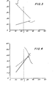
- FIG. 3 A graph depicting hydrogen yield against activity for both the microspheres of this example and standard commercial catalyst is shown in Fig. 3.
- the lines that appear in the Figure were drawn by calculating the first order least square fit for each set of applicable data recorded in Tables II and III and then drawing lines based on those calculations.
- the hydrogen yields of the microspheres of this example and of standard commercial catalyst were about 0.02 wt.% and about 0.06 wt.%, respectively.
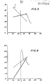
- FIG. 4 A graph depicting coke yield against activity for both the catalyst of this example and standard commercial catalyst is shown in Fig. 4.
- the lines that appear in Fig. 4 were drawn using the least square fit procedure used to draw the lines in Fig. 3.
- the coke yields of the microspheres of this example and of standard commercial catalyst were about 2.8 wt.% and about 3.1 wt.%, respectively.
- the stability of the microspheres of this example in the presence of nickel and vanadium was determined by depositing vanadium and nickel on the microspheres and then determining the deactivated activity of the resulting microspheres.
- the steaming procedure that was used in connection with determining the deactivated activity of metals contaminated catalysts in this application was the "closed system” procedure described in Appendix A of the publication entitled “Engelhard Procedure For The Hyrdothermal Deactivation Of Fluid Catalytic Cracking Catalysts" identified above.
- the nickel and vanadium were deposited on the microspheres by the following procedure:
- microspheres that are contaminated with metals according to the above procedure.
- 50 g. of microspheres rather than 210 g. of microspheres could be contaminated with metals according to this procedure.
- 50 g. of microspheres were contaminated, then the quantities of the other materials used would have to be adjusted proportionally.
- nickel and vanadium naphthenate solutions equivalent to those marketed by ROC-RIC Chemicals may be used in the above procedure.
- microspheres of this example had a deactivated activity of 3.88.
- standard commercial catalyst with 1950 ppm nickel and 3810 ppm vanadium deposited on it, had a deactivated activity of 0.94.
- the deactivated activity of the metals con - taminated microspheres of the present example was 4.1 times the deactivated activity of the metals contaminated standard commercial catalyst.
- the metals contaminated microspheres of this example exhibit a severely deactivated activity that was 4.6 times the severely deactivated activity of the metals contaminated standard commercial catalyst.
- the microspheres When the Y-faujasite content of the microspheres reached about 60% by weight, the microspheres were separated from their mother liquor by vacuum filtration on three 18.5 cm. diameter Buchner funnels. The microspheres were washed with H 2 0 and dried at room temperature.
- the above procedure was repeated four times, yielding about 6800 g. of microspheres.
- the average Y-faujasite content of the microspheres was 59% by weight.
- the average crystalline unit cell size was about 24.69 ⁇ .
- the dried microspheres were ion exchanged with ammonium ions by the following procedure:
- ammonium ion containing microspheres were then ion exchanged with rare earth ions as follows:
- An additional ion exchange with rare earth ions was conducted by: (a) mixing 37.3 g. of the mixed rare earth chloride solution described in the preceding paragraph with 8753 g. of H 2 0; (b) adjusting the pH of the solution to 3.5 with HNO 3 ; (c) adding to the rare earth solution, with stirring, the rare earth ion containing microsphers prepared above; (d) adjusting the pH of the slurry to 3.5 with HNO 3 ; and (e) heating the slurry to 82°C and maintaining the slurry at that temperature for two hours.
- the slurry was then vacuum filtered.
- the microspheres were washed with H 2 O and dried at room temperature.
- the microspheres (including both the zeolitic and non-zeolitic components) contained 0.23% by weight Na 2 0 and 7.0% by weight REO and had a SiO 2 /Al 2 O 3 molar ratio of about 2.23 (52.4% by weight Si0 2 and 39.8% by weight Al 2 O 3 , both on a volatile free basis).
- the microspheres had 0.13 cc/g. of pores having diameters in the range of 2-10 nm, 0.04 cc/g. of pores having diameters in the range of 10-60 nm, 0.11 cc/g. of pores having diameters in the range of 60-2000 nm, a total porosity of 0.25 cc/g., a surface area of 478 m 2 /g and a bulk density of the 0,053/0.074 mm fraction of 0.94 g/ c c.
- the EAI of the microspheres was 0.94%/sec.
- the EAI of the microspheres of this example was, therefore, 3.5 times that of standard commercial catalyst.
- the deactivated and severely deactivated activities of the microspheres of this example were 6.90 and 5.33, respectively. Each of these values is the average of three separate activity determinations made on three samples that had been hydrothermally deactivated, separately, under the appropriate conditions.
- the deactivated activity of the microspheres of this example therefore, is 2.6 times that of standard commercial catalyst and the severely deactivated activity of the microspheres of this example, therefore, is 3.5 times that of standard commercial catalyst.
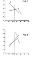
- FIG. 5 A graph of hydrogen yield against activity for both the microspheres of this example and for standard commercial catalyst is shown in Fig. 5.
- the lines that appear in the Figure were drawn by calculating the first order least square fit for each set of applicable data recorded In Tables III and IV (with one exception) and then drawing lines based on those calculations. The one exception was that the fourth line for hydrogen yield in Table IV was ignored for the purpose of calculating the least square fit because the information in that line appeared to be erroneous.
- the hydrogen yields of the microspheres of this example and of standard commercial catalyst were about 0.06%.wt.% and about 0.06 wt.%, respectively.
- a graph of coke yield against activity for both the microspheres of this example and for standard commercial catalyst is shown in Fig. 6.
- the lines that were drawn in the graph were drawn by calculating the first order least square fit for each set of applicable data recorded in Tables III and IV and then drawing lines based on the calculations.
- the coke yields of the microspheres of this example and of standard commercial catalyst were about 2.1 wt.% and about 3.1 wt.%, respectively.
- the stability of the microspheres of this example in the presence of nickel and vanadium was determined by depositing 3600 ppm of vanadium and 1870 ppm of nickel on 200 g. (on a volatile free basis) of the microspheres using the procedure described in Example 1 and then determining the deactivated activity of the metals contaminated microspheres.
- the metals contaminated microspheres of this example had a deactivated activity of 3.09, which was 3.3 times the deactivated activity of metals contaminated standard commercial catalyst.
- the severely deactivated activity of the metals contaminated microspheres of this example was 3.2 times that of metals contaminated standard commercial catalyst.
- a mixture containing aged amorphous zeolite initiator was prepared by the followng procedure:
- the second sodium silicate solution above was a concentrated mother liquor by-product produced during the manufacture of an Engelhard commercial catalyst.
- the above ingredients were added to the reactor, in order, with stirring.
- the ingredients were heated to 99-101 °C to initiate the crystallization reaction and maintained at that temperature, with stirring, for 24.5 hours.
- microspheres were zeolite crystallized in them were separated from their mother liquor by vacuum filtration on an 18.5 cm. diameter Buchner funnel. The microspheres were washed with H 2 0 and dried overnight at room temperature.
- the dried microspheres weighed about 1250 g. and contained 72% by weight Y-faujasite zeolite having a crystalline unit cell size of about 2,47 nm:
- the dried microspheres were added to about 1900 g. of a stirred solution of NH4NO3 (containing 27% by weight NH 4 N0 3 ).
- the resulting slurry was adjusted to a pH of 3.5 with HNO 3 and heated to 82°C . After 1 hour at 82°C, the slurry was vacuum filtered and the microspheres were washed with H 2 0.
- the ion exchange described in the preceding paragraph was repeated fifteen additional times. After the last exchange, the washed microspheres were dried at room temperature overnight. The resulting microspheres contained 0.35% by weight Na 2 0.
- ammonium ion containing microspheres were then ion exchanged with rare earth ions as follows:
- the microspheres (including both the zeolitic and non-zeolitic components) contained 0.35% by weight Na 2 0 and 7.1% by weight REO and had a SiO 2 /Al 2 O 3 , molar ratio of 2.31 (52.6% by weight SiO 2 and 38.7% by weight Al 2 O 3 , both on a volatile free basis).
- the microspheres had 0.10 cc/g. of pores having diameters in the range of 2-10 nm , 0.04 cc/g. of pores having diameters in the range of 10-50 nm ., 0.18 cc/g. of pores having diameters in the range of 60-2000 nm, a total porosity of 0.29 cc/g., a surface area of 477 m 2 /g. and a bulk density of the 0,053/0,074 mm fraction of 0.89 g/cc.
- the EAI of the microspheres was 1.2%/sec.
- the EAI of the microspheres of this example was, therefore, 4.4 times that of standard commercial catalyst.
- the deactivated and severely deactivated activities of the microspheres of this example were 5.94 and 3.76, respectively. Each of these values is the average of three separate activity determinations made on three samples that had been hydrothermally deactivated, separately, under the appropriate conditions.
- the deactivated activity of the microspheres of this example therefore, is 2.2 times that of standard commercial catalyst and the severely deactivated activity of the microspheres of this example, therefore, is 2.5 times that of standard commercial catalyst.
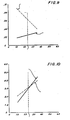
- FIG. 7 A graph of hydrogen yield agaist activity for both the microspheres of this example and-for standard commercial catalyst is shown in Fig. 7.
- the lines that were drawn in the Figure were obtained by calculating the first order least square fit for each set of applicable data recorded in Tables III and V and then drawing lines based on those calculations.
- the hydrogen yields of the microspheres of this example and of standard commercial catalyst were about 0.05 wt.% and about 0.06 wt.%, respectively.
- FIG. 8 A graph of coke yield against activity for both the microspheres of this example and for standard commercial catalyst is shown in Fig. 8.
- the lines that were drawn in the Figure were obtained by calculating the first order least square fit for each set of applicable data recorded in Tables III and V and then drawing a line based on those calculations.
- the coke yields of the microspheres of this examples and standard commercial catalyst were about 3.2 wt.% and about 3.1 wt.%, respectively.
- the stability of the microspheres of this example in the presence of nickel and vanadium was determined by depositing 3940 ppm of vanadium and 1925 ppm of nickel on 220 g. (on a volatile free basis) of the microspheres using the procedure described in Example 1 and then determining the deactivated activity of the metals contaminated microspheres.
- microspheres of this example with the metals deposited on them, had a deactivated activity of 2.45 which was 2.6 times the deactivated activity of the metals contaminated standard commercial catalyst.
- the severely deactivated activity of the metals contaminated microspheres of this example was 2.2 times that of metals contaminatd standard commercial catalyst.
- Microspheres comprising a mixture of metakaolin and kaolin clay that has been calcined to contain a substantial amount of mullite were prepared by the following procedure:
- a mixture containing amorphous zeolite initiator was prepared by the following procedure:
- the above ingredients were added to the reactor, in order, with stirring.
- the ingredients were heated to 99-101°C to initiate the crystallization reaction and maintained at that temperature, with stirring, for 12.5 hours.
- microspheres with zeolite crystallized in them were separated from their mother liquor by vacuum filtration on three, 18.5 cm. diameter Buchner funnels. The microspheres were washed with H 2 0 and dried at about 65°C overnight.
- the dried microspheres weighed about 1500 g. and contained 59% by weight Y-faujasite zeolite having a crystalline unit cell size of about 2,47 nm.
- the slurry was vacuum filtered, the microspheres were washed with H 2 0 and the washed microspheres were dried overnight.
- the dried microspheres were then added to 2200 g. of a solution containing 27% by weight of NH 4 NO 3 , with stirring.
- the resulting slurry was adjusted to a pH of 3.5 with HNO 3 and heated to 82 ° C . After one hour at 82° C , the slurry was vacuum filtered and the microspheres were washed with H 2 0.
- microspheres contained 0.3% by weight Na20.
- ammonium ion containing microspheres were then ion exchanged with rare earth ions as follows:
- the dried microspheres were added to 2200 g. of H 2 0 at room temperature, with stirring. To this was added 20.3 g. of the mixed rare earth chloride solution described in the preceding paragraph. The pH of the slurry was adjusted to 3.3 with HN0 3 . The slurry was heated to 82°C. After one hour at 82°C, the slurry was vacuum filtered and the microspheres were washed with H 2 0 and dried overnight at room temperature.
- the microspheres were then added to 2265 g. of H 2 0 at room temperature, with stirring. To this was added 41.1 g. of the mixed rare earth chloride solution described in this example. The pH of the slurry was adjusted to 3.3 with HNO 3 . The slurry was then heated to 82°C . After one hour at 82 ° C , the slurry was vacuum filtered and the microspheres were washed with H 2 0 and dried overnight at room temperature.
- the sample was then ion exchanged with ammonium ions as follows: At room temperature, the microspheres were added to 2176 g. of a solution containing 27% by weight NH 4 NO 3 , with stirring. The pH of the slurry was 4.8. The slurry was then heated to 82°C. After about 1 ⁇ 2 hour at 82°C, the slurry was vacuum filtered. The microspheres were washed with H 2 O and dried at room temperature overnight.
- a final ion exchange with rare earth ions was then conducted as follows: At room temperature, the microspheres were added to 2120 g. of H 2 0. To this was added 385 g. of mixed rare earth chloride solution described in this example. The pH of the slurry was adjusted to 3.3 with HNO 3 . The slurry was heated to 82°C. After one hour at 82°C, the slurry was vacuum filtered. The microspheres were washed with H 2 0 and dried overnight at room temperature.
- the microspheres (including both the zeolitic and non-zeolitic components) contained 0.25% by weight Na 2 0 and 7.2% by weight REO and had a SiO 2 /Al 2 O 3 molar ratio of about 2.38 (53.5% by weight Si0 2 and 38.1% by weight Al 2 O 3 , both on a volatile free basis).
- the microspheres had 0.02 cc/g. of pores having diameters in the range of 2-10 nm , 0.07 cc/g. of pores having diameters in the range of 10-60 nm, 0.12 cc/g. of pores having diameters in the range of 60-2000 nm , a total porosity of 0.20 cc/g., a surface area of 430 m 2 /g and a bulk density of the 0,053/0,074 mm fraction of 1.16 g/cc.
- the EAI of the microspheres was 0.37%/sec.
- the EAI of the microspheres of this example was, therefore, 1.4 times that of standard commercial catalyst.
- the deactivated and severely deactivated activities of the microspheres of this example were 6.50 and 3.63, respectively.
- the deactivated activity value is the average of three separate activity determinations made on three samples that had been hydrothermally deactivated, separately, under the appropriate conditions.
- the severely deactivated activity value is the average of four separate activity determinations that were made on four samples that had been hydrothermally deactivated, separately, under the appropriate conditions.
- the deactivated activity of the microspheres of this example therefore, is 2.4 times that of standard commercial catalyst and the severely deactivated activity of the microspheres of this example, therefore, is 2.4 times that of standard commercial catalyst.
- FIG. 9 A graph of hydrogen yield against activity for both the microspheres of this example and for standard commercial catalyst is shown in Fig. 9.
- the lines that were drawn in the Figure were obtained by calculating the first order least square fit for each set of applicable data recorded in Tables III and VI and then drawing lines based on those calculations.
- the hydrogen yields of the microspheres of this example and of standard commercial catalyst were about 0.03 wt.% and about 0.06 wt.%, respectively.
- a graph of coke yield against activity for both the microspheres of this example and for standard commercial catalyst is shown in Fig. 10.
- the lines that were drawn in the Figure were obtained by calculating the first order least square fit for each set of applicable data recorded in Tables III and VI and then drawing lines based on those calculations.
- At 70% measured conversion the coke yields of the microspheres of this example and standard commercial catalyst were about 3.0 wt.% and about 3.1 wt.%, respectively.
- the stability of the microspheres of this example in the presence of nickel and vanadium was determined by depositing 4260 ppm of vanadium and 2260 ppm of nickel on 210 g. (on a volatile free basis) of the microspheres using the procedure described in Example 1 and then determining the deactivated activity of the metals contaminated microspheres.
- microspheres of this example with the metals deposited on them, had a deactivated activity of 1.23 which was 1.3 times the deactivated activity of the metals contaminated standard commercial catalyst.
- the severely deactivated activity of the metals contaminated microspheres of this example was 0.6 times the severely deactivated activity of the metals contaminated standard commercial catalyst.
- This example illustrates the crystallization of more than 40% by weight Y-faujasite in microspheres derived from calcined clay comprising a mixture of metakaolin and kaolin clay that was calcined substantially through its characteristic exotherm without any substantial formation of mullite, in which the two types of calcined clay are in separately formed microspheres.
- microspheres of calcined clay that were used in this example were obtained from a supply of those microspheres at an Engelhard facility. We do not know the precise conditions under which those microspheres were made. We believe that the microspheres of calcined clay were made from microspheres of hydrous clay that were made by a process of the type described in U.S. Patent 3,663,165 (Example 1, col. 6, lines 44-57).
- the microspheres of calcined clay that were calcined substantially through the characteristic exotherm were made by calcining the hydrous microspheres under appropriate conditions (e.g., for 2 hours in a muffle furnace at a chamber temperature of 982° C ).
- the microspheres of metakaolin were made by calcining the microspheres of hydrous clay under appropriate conditions (e.g., for 2 hours in a muffle furnace at a temperature of 732°C ).
- a mixture containing amorphous zeolite initiator was prepared by the following procedure:
- the above ingredients were added to the reactor, in order, with stirring.
- the ingredients were heated to 99-101°C to initiate the crystallization processs and maintained at that temperature, with stirring, for 20 hours.
- microspheres with zeolite crystallized in them were separated from their mother liquor by vacuum filtration on an 11 cm. diameter Buchner funnel.
- the microspheres were washed with H 2 0 and dried at room temperature.
- the dried microspheres contained 44% by weight Y-faujasite zeolite having a crystalline unit cell size of about 2,467 nm.
- the microspheres had 0.08 cc/g. of pores having a diameters in the range of 2 - 10 nm, 0.02 cc/g. of pores having diameters in the range of 10-60 nm , 0.03 cc/g. of pores having diameters in the range of 60-2000 nm, a total porosity of 0.13 cc/g., and a surface area of 345 m 2 /g.
- This example illustrates the preparation of microspheres of the catalyst of the present invention in which: (a) the non-zeolitic component of the microspheres was derived from a mixture of metakaolin and clay that was calcined through its characteristic exotherm without any substantial formation of mullite in which the two types of calcined clay were present in the same microspheres; (b) the clay that was calcined through the characteristic exotherm was made from ASP@900 hydrous clay (a commercially available hydrous kaolin clay described in the Engelhard Technical Bulletin entitled "Aluminum Silicate Pigments" identified above); and (c) the zeolite crystallization process was internally seeded with a mixture containing amorphous zeolite initiator.
- ASP@900 hydrous clay a commercially available hydrous kaolin clay described in the Engelhard Technical Bulletin entitled "Aluminum Silicate Pigments” identified above
- a mixture containing amorphous zeolite initiator was prepared on a commercial scale by the following procedure:
- 880 g. of ASP@900 hydrous kaolin clay was calcined in a muffle furnace for one hour at a chamber temperature of 1093°C to calcine the clay through its characteristic exotherm without any substantial formation of mullite.
- the preceding calcination process was repeated for several batches of 880 g. of ASP@900 hydrous kaolin clay.
- the calcined clay was pulverized by passing it two times through a Mikro Pulverizer® of the type described in Example 4.
- a slurry was prepared by mixing 1500 g. of the calcined kaolin prepared in the preceding paragraph, 1500 g. of ASP®600 hydrous kaolin, 1285.9 g of the mixture containing amorphous zeolite initiator described above, and 4000 g. of deionized H 2 O.
- a 4,2 cm bed of the spray dried microspheres was calcined in a muffle furnace for two hours at a chamber temperature of 732°C to convert the hydrous kaolin in the microspheres to metakaolin. This procedure was repeated until all the microspheres had been calcined to convert the hydrous clay to metakaolin. Each tray containing a bed of microspheres was taken out of the muffle furnace after the first hour of calcination, rotated 180°, and placed back into the furnace for the second hour of calcination.
- the first sodium silicate solution above was a concentrated mother liquor by-product produced during the manufacture of an Engelhard commercial catalyst.
- the above ingredients were added to the reactor, in order, with stirring.
- the resulting slurry had a molar ratio of H 2 0/Na 2 0 in the solution phase of about 24, a weight ratio of SiO 2 in the solution phase to microspheres of calcined clay of about 1.35 and a molar ratio of Na 2 O/SiO 2 in the solution phase of about 0.50.
- the slurry as heated to 98-99°C to initiate the crystallization process and was maintained at that temperature, with stirring, for 21 hours.
- microspheres with zeolite crystallized in them were separated from their mother liquor by vacuum filtration on two 18.5 cm diameter Buchner funnels. The microspheres were washed with H 2 0.
- microspheres were then washed with two liters of acetone, dried on the vacuum filter for 4 hours and dried in air for 2-3 hours.
- the dried microspheres weighed about 1943 g. and contained about 57% by weight Y-faujasite zeolite having a crystalline unit cell size of about 2,471 nm.
- a mixed rare earth chloride solution was prepared by mixing 490 g. of a concentrated mixed rare earth chloride solution (containing the equivalent of about 18.4% by weight La 2 0 3 , 6.3% by weight Nd 2 O 3 , 1.4% by weight CeO 2 , 0.9% by weight Pr 6 O 11 and 0.3% by weight Sm 2 O 3 ) with 1985 g. of H 2 0.
- the pH of the solution was adjusted to 3.2 with HN0 3 .
- the ammonium ion exchanged microspheres were added to the solution containing rare earth chlorides, with stirring. After the microspheres were added, the pH was adjusted to 3.2 with HN0 3 .
- the slurry was heated to 82 ° C and kept at that temperature, with stirring, for 15 minutes.
- the slurry was then vacuum filtered and the microspheres were washed with H 2 0.
- the microspheres were dried on the vacuum filter for 30 minutes and then dried at room temperature for 1 day.
- the microspheres (including both the zeolitic and non-zeolitic components) contained 0.34% by weight Na 2 0 and 7.30% by weight REO and had an SiO 2 /Al 2 O 3 molar ratio of 2.85 (59.5% by weight SiO 2 and 35.4% by weight A1 2 0 3 , both on a volatile free basis).
- the microspheres had 0.07 cc/g. of pores having diameters in the range of 2-10 nm, 0.03 cc/g. of pores having diameters in the range of 10-60 nm, 0.004 cc/g. of pores having diameters in the range of 50-2000 nm , a total porosity of 0.09 cc/g., a surface area of 500 m 2 /g. and a bulk density of the 0.053/0.074 mm fraction of 1.12 g/cc.
- the EAI of the microspheres was 0.41%/second.
- the EAI of the microspheres of this example therefore, was about 1.5 times the EAI of standard commercial catalyst.
Applications Claiming Priority (2)
| Application Number | Priority Date | Filing Date | Title |
|---|---|---|---|
| US469765 | 1983-02-25 | ||
| US06/469,765 US4493902A (en) | 1983-02-25 | 1983-02-25 | Fluid catalytic cracking catalyst comprising microspheres containing more than about 40 percent by weight Y-faujasite and methods for making |
Related Child Applications (1)
| Application Number | Title | Priority Date | Filing Date |
|---|---|---|---|
| EP88116053.5 Division-Into | 1984-02-24 |
Publications (3)
| Publication Number | Publication Date |
|---|---|
| EP0117545A2 true EP0117545A2 (fr) | 1984-09-05 |
| EP0117545A3 EP0117545A3 (en) | 1986-09-10 |
| EP0117545B1 EP0117545B1 (fr) | 1990-08-29 |
Family
ID=23864977
Family Applications (2)
| Application Number | Title | Priority Date | Filing Date |
|---|---|---|---|
| EP84101946A Expired - Lifetime EP0117545B1 (fr) | 1983-02-25 | 1984-02-24 | Catalyseur de craquage catalytique fluidisé comprenant des microsphères contenant plus que 40% en poids de faujasite Y et méthode pour sa préparation et son emploi |
| EP88116053A Withdrawn EP0308989A1 (fr) | 1983-02-25 | 1984-02-24 | Catalyseur de craquage catalytique fluidisé comprenant des microsphères contenant plus que 40 % en poids de faujasite-Y et méthode pour sa préparation et son utilisation |
Family Applications After (1)
| Application Number | Title | Priority Date | Filing Date |
|---|---|---|---|
| EP88116053A Withdrawn EP0308989A1 (fr) | 1983-02-25 | 1984-02-24 | Catalyseur de craquage catalytique fluidisé comprenant des microsphères contenant plus que 40 % en poids de faujasite-Y et méthode pour sa préparation et son utilisation |
Country Status (11)
| Country | Link |
|---|---|
| US (1) | US4493902A (fr) |
| EP (2) | EP0117545B1 (fr) |
| JP (1) | JPH0628733B2 (fr) |
| AR (1) | AR247678A1 (fr) |
| AU (1) | AU577521B2 (fr) |
| BR (1) | BR8400877A (fr) |
| CA (1) | CA1218641A (fr) |
| DE (3) | DE117545T1 (fr) |
| IN (1) | IN163191B (fr) |
| MX (1) | MX171329B (fr) |
| ZA (1) | ZA841265B (fr) |
Cited By (9)
| Publication number | Priority date | Publication date | Assignee | Title |
|---|---|---|---|---|
| EP0138396A2 (fr) * | 1983-09-15 | 1985-04-24 | Engelhard Corporation | Préparation de catalyseurs de craquage |
| EP0187007A2 (fr) * | 1984-12-14 | 1986-07-09 | Engelhard Corporation | Mullite poreuse |
| EP0194101A2 (fr) * | 1985-03-01 | 1986-09-10 | Engelhard Corporation | Catalyseur faujasite, sa préparation et son application pour le craquage d'une charge pétrolière |
| EP0200515A2 (fr) * | 1985-04-29 | 1986-11-05 | Engelhard Corporation | Méthode de préparation de catalyseur de craquage fluidisé à partir de fines de rebut provenant de préparation de catalyseur |
| EP0204455A2 (fr) * | 1985-06-05 | 1986-12-10 | Engelhard Corporation | Méthode de préparation de germes en solution utiles pour la fabrication de catalyseurs zéolithiques |
| EP0365336A2 (fr) * | 1988-10-20 | 1990-04-25 | Engelhard Corporation | Catalyseurs zéolitiques pour craquage en lit fluidisé et préparation de ces catalyseurs |
| EP0369629A2 (fr) * | 1988-11-16 | 1990-05-23 | Engelhard Corporation | Catalyseurs FCC à haute teneur en zéolite et procédé pour les préparer |
| US5023220A (en) * | 1988-11-16 | 1991-06-11 | Engelhard Corporation | Ultra high zeolite content FCC catalysts and method for making same from microspheres composed of a mixture of calcined kaolin clays |
| WO1996030120A1 (fr) * | 1995-03-31 | 1996-10-03 | Engelhard Corporation | Catalyseurs de craquage catalytique fluide modifies sous forme de microspheres, et leur fabrication |
Families Citing this family (85)
| Publication number | Priority date | Publication date | Assignee | Title |
|---|---|---|---|---|
| US4493902A (en) * | 1983-02-25 | 1985-01-15 | Engelhard Corporation | Fluid catalytic cracking catalyst comprising microspheres containing more than about 40 percent by weight Y-faujasite and methods for making |
| US4606813A (en) * | 1983-02-25 | 1986-08-19 | Engelhard Corporation | Fluid catalytic cracking catalyst for cracking sulfur containing petroleum feedstocks and a process for using it |
| US4818509A (en) * | 1984-03-23 | 1989-04-04 | Mobil Oil Corporation | Continuous process for manufacturing crystalline zeolites in continuously stirred backmixed crystallizers |
| JPS6163524A (ja) * | 1984-09-01 | 1986-04-01 | Toa Nenryo Kogyo Kk | バインダ−レス結晶性アルミノ珪酸塩及びその製造方法 |
| JPS61242911A (ja) * | 1985-04-17 | 1986-10-29 | Toyo Soda Mfg Co Ltd | 成形用ゼオライト組成物 |
| US5071539A (en) * | 1985-08-30 | 1991-12-10 | Engelhard Corporation | FCC catalysts of increased effective heat capacity |
| EP0236548A1 (fr) * | 1985-10-18 | 1987-09-16 | KATALISTIKS INTERNATIONAL, Inc. | Catalyseur de craquage et son procédé de fabrication |
| FR2660578B1 (fr) * | 1990-04-09 | 1994-09-23 | Elf Aquitaine | Catalyseur a base d'une faujasite de haut rapport si:al de synthese et son application aux reactions de catalyse acide realisees sur des charges hydrocarbonees. |
| US5236877A (en) * | 1990-12-04 | 1993-08-17 | W. R. Grace & Co.-Conn. | Dual zeolite fluid cracking catalyst composition for improved gasoline octane |
| US5302567A (en) * | 1991-11-04 | 1994-04-12 | W. R. Grace & Co.-Conn. | Zeolite octane additive |
| US5243121A (en) * | 1992-03-19 | 1993-09-07 | Engelhard Corporation | Fluid catalytic cracking process for increased formation of isobutylene and isoamylenes |
| DE69300756T2 (de) * | 1992-04-27 | 1996-05-09 | Grace W R & Co | Krackkatalysatoren und -zusätze. |
| US5300469A (en) * | 1992-12-08 | 1994-04-05 | Engelhard Corporation | Composition for passivating vanadium in catalytic cracking and preparation thereof |
| US5403799A (en) * | 1992-12-21 | 1995-04-04 | W. R. Grace & Co.-Conn. | Process upset-resistant inorganic supports for bioremediation |
| US5395809A (en) * | 1993-11-01 | 1995-03-07 | Engelhard Corporation | Modified microsphere FCC catalysts |
| US5413978A (en) * | 1993-11-30 | 1995-05-09 | Engelhard Corporation | Catalytically inert particles for blending with petroleum cracking catalyst |
| US5521133A (en) * | 1994-11-29 | 1996-05-28 | Engelhard Corporation | Phosphorus bound porous microspheres |
| HU213644B (en) | 1995-11-22 | 1997-12-29 | Mol Magyar Olaj & Gazipari Rt | Additiv catalyst for cracking petroleum fractions, process for making thereof and cracking process |
| US5993645A (en) * | 1995-12-08 | 1999-11-30 | Engelhard Corporation | Catalyst for cracking oil feedstocks contaminated with metal |
| US6756029B2 (en) | 1999-08-11 | 2004-06-29 | Petroleo Brasileiro S.A.-Petrobras | Molecular sieves of faujasite structure |
| US6942784B2 (en) * | 2000-09-22 | 2005-09-13 | Engelhard Corporation | Structurally enhanced cracking catalysts |
| MXPA03002474A (es) * | 2000-09-22 | 2003-07-14 | Engelhard Corp | Catalizadores para la destilacion fraccionada estructuralmente mejorados. |
| US6673235B2 (en) | 2000-09-22 | 2004-01-06 | Engelhard Corporation | FCC catalysts for feeds containing nickel and vanadium |
| US6656347B2 (en) * | 2000-09-22 | 2003-12-02 | Engelhard Corporation | Structurally enhanced cracking catalysts |
| US20030089640A1 (en) | 2001-10-17 | 2003-05-15 | Rostam Madon | FCC catalysts for feeds containing nickel and vanadium |
| US6696378B2 (en) * | 2001-08-31 | 2004-02-24 | Engelhard Corporation | Fluid catalytic cracking catalyst manufacturing process |
| WO2003054114A2 (fr) * | 2001-10-17 | 2003-07-03 | Engelhard Corporation | Catalyseurs de craquage catalytique fluide (fcc) pour aliments contenant du nickel et du vanadium |
| FI115046B (fi) * | 2001-11-01 | 2005-02-28 | Kautar Oy | Hydraulisesti kovettuva sideaineseos ja menetelmä sen valmistamiseksi |
| US7101473B2 (en) * | 2002-05-31 | 2006-09-05 | Engelhard Corporation | Method of enhancing the activity of FCC catalysts |
| US6864202B2 (en) * | 2002-09-16 | 2005-03-08 | Indian Oil Corporation Limited | Process for preparing sodium silicate alkali solution depleted of sodium salt and enriched in silica |
| CN1275855C (zh) * | 2003-03-28 | 2006-09-20 | 中国石油化工股份有限公司 | 用高岭土合成的纳米级y型沸石及其制备方法 |
| US6942783B2 (en) * | 2003-05-19 | 2005-09-13 | Engelhard Corporation | Enhanced FCC catalysts for gas oil and resid applications |
| US6908603B2 (en) * | 2003-06-02 | 2005-06-21 | Engelhard Corporation | In-situ ZSM-5 synthesis |
| CN1313207C (zh) * | 2004-02-13 | 2007-05-02 | 中国石油天然气集团公司 | 具有高催化活性的均匀纳米分子筛材料的制备方法 |
| US8084383B2 (en) * | 2004-03-16 | 2011-12-27 | W.R. Grace & Co.-Conn. | Gasoline sulfur reduction catalyst for fluid catalytic cracking process |
| US20060060504A1 (en) | 2004-09-08 | 2006-03-23 | Vierheilig Albert A | Additives for metal contaminant removal |
| CN100429149C (zh) * | 2004-11-26 | 2008-10-29 | 中国石油天然气股份有限公司 | 一种高岭土喷雾微球合成高含量NaY分子筛的制备方法 |
| TWI341218B (en) * | 2005-11-14 | 2011-05-01 | Oxy Vinyls Lp | Catalyst compositions and process for oxychlorination |
| CN104673364A (zh) | 2006-03-02 | 2015-06-03 | 巴斯福催化剂公司 | 包含原位形成的y-八面沸石的加氢裂化催化剂和加氢裂化方法 |
| US9433934B2 (en) * | 2006-03-02 | 2016-09-06 | Basf Corporation | In-situ produced Y-faujasite from kaolin-derived, pre-shaped particles and the method of preparation and the use thereof |
| US7572421B2 (en) * | 2006-06-19 | 2009-08-11 | Basf Catalysts Llc | Mercury sorbents and methods of manufacture and use |
| US7753992B2 (en) | 2006-06-19 | 2010-07-13 | Basf Corporation | Methods of manufacturing mercury sorbents and removing mercury from a gas stream |
| CN101172243B (zh) * | 2006-11-01 | 2010-09-15 | 中国石油化工股份有限公司 | 介孔材料/微孔分子筛复合材料及其制备方法 |
| CN101239323B (zh) * | 2007-02-09 | 2011-04-20 | 中国石油化工股份有限公司 | 层状粘土/分子筛复合材料的制备方法 |
| US9108181B2 (en) | 2007-06-20 | 2015-08-18 | Basf Corporation | Structurally enhanced cracking catalysts |
| US8906823B2 (en) | 2007-09-24 | 2014-12-09 | Basf Corporation | Pollutant emission control sorbents and methods of manufacture and use |
| US20090081092A1 (en) * | 2007-09-24 | 2009-03-26 | Xiaolin David Yang | Pollutant Emission Control Sorbents and Methods of Manufacture and Use |
| US8685351B2 (en) | 2007-09-24 | 2014-04-01 | Basf Corporation | Pollutant emission control sorbents and methods of manufacture and use |
| CN101618334B (zh) * | 2008-07-04 | 2013-08-28 | 中国石油化工股份有限公司 | 一种原位型分子筛加氢裂化催化剂及其制备方法 |
| US20100298118A1 (en) * | 2009-05-21 | 2010-11-25 | Zhiping Tan | Fluid catalytic cracking catalyst with low coke yield and method for making the same |
| CN102019196B (zh) * | 2009-09-18 | 2012-12-12 | 中国石油天然气股份有限公司 | 一种改善高岭土微球原位晶化产物孔结构的方法 |
| US8372269B2 (en) | 2009-10-02 | 2013-02-12 | Basf Corporation | Heavy metals trapping co-catalyst for FCC processes |
| CN102049278B (zh) * | 2009-10-27 | 2012-08-29 | 中国石油化工股份有限公司 | 一种小晶粒y型分子筛分散材料 |
| CA2793566C (fr) | 2010-03-18 | 2020-09-29 | W.R. Grace & Co.-Conn. | Procede de fabrication de catalyseurs zeolitiques ameliores a partir d'alumines peptisees |
| US8845882B2 (en) | 2010-03-18 | 2014-09-30 | W. R. Grace & Co.-Conn. | High light olefins FCC catalyst compositions |
| WO2011115746A1 (fr) | 2010-03-18 | 2011-09-22 | W. R. Grace & Co.-Conn. | Procédé de fabrication de catalyseurs améliorés à partir de zéolites dérivées de l'argile |
| CN102372281B (zh) * | 2010-08-25 | 2013-07-31 | 中国石油天然气股份有限公司 | 一种NaY沸石的制备方法 |
| CN102091648B (zh) * | 2010-11-09 | 2012-12-19 | 中国海洋石油总公司 | 一种全白土型脱烯烃催化剂的制备方法 |
| CN102553630B (zh) * | 2010-12-16 | 2014-10-22 | 华东理工大学 | 高硅铝比小晶粒y型沸石催化裂化催化剂及其制备方法 |
| US9029291B2 (en) * | 2011-01-12 | 2015-05-12 | Basf Corporation | Rare earth-containing attrition resistant vanadium trap for catalytic cracking catalyst |
| US20120227629A1 (en) * | 2011-03-08 | 2012-09-13 | Basf Corporation | Beneficial Thermo-Chemical Treatment of Kaolin with Ammonium Polyphosphate |
| US8940156B2 (en) * | 2011-03-08 | 2015-01-27 | Basf Corporation | Thermochemical structuring of matrix components for FCC catalysts |
| CN102839010A (zh) * | 2011-06-23 | 2012-12-26 | 中国石油天然气集团公司 | 一种同时具有酸性和碱性的改性镁铝尖晶石的制备方法 |
| TWI595926B (zh) * | 2011-11-04 | 2017-08-21 | 巴地斯公司 | 具增進之活性及水熱穩定性之經磷改質的裂解催化劑 |
| US20150027871A1 (en) * | 2012-02-17 | 2015-01-29 | Kior, Inc. | Catalyst Compositions Comprising In Situ Grown Zeolites on Clay Matrixes Exhibiting Hierarchical Pore Structures |
| WO2013123297A2 (fr) * | 2012-02-17 | 2013-08-22 | Kior, Inc. | Composition de catalyseur ayant une accessibilité accrue de site actif en volume pour la thermoconversion catalytique de biomasse en carburants liquides et produits chimiques et pour la valorisation de biohuiles |
| CN102658193A (zh) * | 2012-03-31 | 2012-09-12 | 山东多友科技有限公司 | 一种烃类裂化催化剂的制备方法 |
| KR20150110535A (ko) | 2013-01-23 | 2015-10-02 | 바스프 코포레이션 | 개선된 제올라이트와 인의 상호작용에 의한 zsm-5 첨가제의 활성 증진 |
| US9403161B2 (en) * | 2013-06-17 | 2016-08-02 | Basf Corporation | Method of producing FCC catalysts with reduced attrition rates |
| EP3016738B1 (fr) | 2013-07-04 | 2019-04-24 | Total Research & Technology Feluy | Compositions de catalyseur comprenant des cristaux de tamis moléculaires de petite taille déposés sur un matériau poreux |
| EP3057704A4 (fr) * | 2013-10-15 | 2016-11-02 | Basf Corp | Catalyseurs de craquage catalytique en lit fluidisé mésoporeux présentant une excellente résistance à l'attrition |
| US9895680B2 (en) | 2013-12-19 | 2018-02-20 | Basf Corporation | FCC catalyst compositions containing boron oxide |
| US20150174559A1 (en) * | 2013-12-19 | 2015-06-25 | Basf Corporation | Phosphorus-Modified FCC Catalysts |
| US9441167B2 (en) | 2013-12-19 | 2016-09-13 | Basf Corporation | Boron oxide in FCC processes |
| US9796932B2 (en) | 2013-12-19 | 2017-10-24 | Basf Corporation | FCC catalyst compositions containing boron oxide and phosphorus |
| EP3102324B1 (fr) | 2014-02-07 | 2021-09-22 | BASF Corporation | Catalyseur de pyrolyse flash d'une charge oxygénée |
| JP6743045B2 (ja) | 2015-04-09 | 2020-08-19 | ビーエーエスエフ コーポレーション | Zsm−5触媒 |
| US10507460B2 (en) * | 2015-11-24 | 2019-12-17 | Basf Corporation | Fluid catalytic cracking catalysts for increasing butylene yields |
| US10633596B2 (en) | 2016-06-17 | 2020-04-28 | Basf Corporation | FCC catalyst having alumina derived from crystalline boehmite |
| EP3609616A4 (fr) * | 2017-04-14 | 2020-12-09 | BASF Corporation | Catalyseur de craquage catalytique fluide à faible teneur en coke et rendement élevé en essence et à haute activité |
| CN110636901A (zh) | 2017-05-17 | 2019-12-31 | 巴斯夫公司 | 底部残留物改质和低焦炭流化催化裂化催化剂 |
| US10894248B2 (en) * | 2018-09-13 | 2021-01-19 | Indian Oil Corporation Limited | Catalyst composition for enhancing yield of olefins in fluid catalytic cracking process (FCC) |
| WO2021091816A1 (fr) | 2019-11-04 | 2021-05-14 | Basf Corporation | Compositions d'aluminosilicate poreux pour l'élimination de métaux contaminants dans le traitement de l'eau |
| WO2021239944A1 (fr) | 2020-05-29 | 2021-12-02 | Basf Se | Catalyseur pour l'oxydation de chlorure d'hydrogène et sa production |
| CN112919493B (zh) * | 2021-02-05 | 2022-10-14 | 正大能源材料(大连)有限公司 | 一种低成本制备ssz-13分子筛的方法及应用 |
Citations (8)
| Publication number | Priority date | Publication date | Assignee | Title |
|---|---|---|---|---|
| US3647718A (en) * | 1969-03-25 | 1972-03-07 | Engelhard Min & Chem | Microspherical zeolitic molecular sieve composite catalyst and preparation thereof |
| GB1342977A (en) * | 1970-09-24 | 1974-01-10 | Grace W R & Co | Process for preparing attrition resistant zeolitc particles |
| US4215015A (en) * | 1979-02-02 | 1980-07-29 | Uop Inc. | High octane FCC catalyst |
| US4235753A (en) * | 1979-03-16 | 1980-11-25 | Engelhard Minerals & Chemicals Corporation | Zeolitized composite bodies and manufacture thereof |
| US4259212A (en) * | 1978-06-07 | 1981-03-31 | Exxon Research And Engineering Co. | Octane improvement cracking catalyst |
| GB2084892A (en) * | 1980-10-10 | 1982-04-21 | Exxon Research Engineering Co | Hydrocarbon conversion zeolite- containing catalysts and processes utilizing the same |
| US4326993A (en) * | 1979-12-17 | 1982-04-27 | Mobil Oil Corporation | Novel cracking catalysts and catalyst supports |
| US4357265A (en) * | 1980-10-28 | 1982-11-02 | W. R. Grace & Co. | Catalytic cracking catalyst |
Family Cites Families (58)
| Publication number | Priority date | Publication date | Assignee | Title |
|---|---|---|---|---|
| US3140249A (en) * | 1960-07-12 | 1964-07-07 | Socony Mobil Oil Co Inc | Catalytic cracking of hydrocarbons with a crystalline zeolite catalyst composite |
| US3119659A (en) * | 1960-09-26 | 1964-01-28 | Union Carbide Corp | Process for producing molecular sieve bodies |
| US3119660A (en) * | 1960-09-26 | 1964-01-28 | Union Carbide Corp | Process for producing molecular sieve bodies |
| NL302055A (fr) * | 1962-12-27 | |||
| US3338672A (en) * | 1964-02-25 | 1967-08-29 | Minerals & Chem Philipp Corp | Method for making a faujasite-type crystalline zeolite |
| US3390958A (en) * | 1964-10-19 | 1968-07-02 | Union Carbide Corp | Process for preparing crystalline zeolitic molecular sieves |
| US3391994A (en) * | 1964-12-08 | 1968-07-09 | Engelhard Min & Chem | Method for producing faujasitetype zeolites |
| US3393156A (en) * | 1965-09-20 | 1968-07-16 | Union Oil Co | Pelleted zeolite compositions |
| US3433587A (en) * | 1965-10-22 | 1969-03-18 | Engelhard Min & Chem | Method for preparing crystalline zeolite catalyst |
| US3472617A (en) * | 1965-12-20 | 1969-10-14 | Grace W R & Co | Production of binderless molecular sieve aggregates |
| US3674538A (en) * | 1965-12-20 | 1972-07-04 | Matsushita Electric Ind Co Ltd | Heat-sensitive sheet |
| US3367886A (en) * | 1966-02-16 | 1968-02-06 | Engelhard Min & Chem | Synthetic zeolite contact masses and method for making the same |
| US3367887A (en) * | 1966-02-25 | 1968-02-06 | Engelhard Min & Chem | Solid catalysts |
| US3433589A (en) * | 1966-04-07 | 1969-03-18 | Mobil Oil Corp | Method of preparing faujasite-type crystalline zeolites |
| US3492090A (en) * | 1966-04-07 | 1970-01-27 | Mobil Oil Corp | Process for producing faujasite |
| US3458454A (en) * | 1966-07-29 | 1969-07-29 | Air Prod & Chem | Fluidizable cracking catalyst |
| US3515511A (en) * | 1967-08-22 | 1970-06-02 | Air Prod & Chem | Faujasite production |
| US3507778A (en) * | 1967-09-05 | 1970-04-21 | Exxon Research Engineering Co | Cracking petroleum fractions with a crystalline zeolite catalyst in combination with a phosphate promoted silica-magnesia catalyst |
| US3592760A (en) * | 1967-09-20 | 1971-07-13 | Union Oil Co | Catalytic hydrocracking |
| US3503900A (en) * | 1968-01-17 | 1970-03-31 | Engelhard Min & Chem | Fluid catalyst and preparation thereof |
| US3506594A (en) * | 1968-06-20 | 1970-04-14 | Engelhard Min & Chem | Microspherical zeolitic molecular sieve composite catalyst and preparation thereof |
| US3574538A (en) * | 1968-10-17 | 1971-04-13 | Grace W R & Co | Process for preparing high silica faujasite |
| JPS5422953B1 (fr) * | 1969-01-02 | 1979-08-10 | ||
| US3515683A (en) * | 1969-01-28 | 1970-06-02 | Air Prod & Chem | Cerium faujasite catalyst |
| JPS546519B1 (fr) * | 1969-02-03 | 1979-03-29 | ||
| US3657154A (en) * | 1969-09-09 | 1972-04-18 | Engelhard Min & Chem | Microspherical zeolitic cracking catalyst |
| US3875081A (en) * | 1969-10-24 | 1975-04-01 | Union Oil Co | Hydrocarbon conversion catalyst |
| US3642662A (en) * | 1969-11-17 | 1972-02-15 | Air Prod & Chem | Synthesis of sodium faujasite |
| US3663165A (en) * | 1970-02-09 | 1972-05-16 | Engelhard Min & Chem | Zeolitic catalyst and preparation |
| US3639099A (en) * | 1970-08-13 | 1972-02-01 | Grace W R & Co | Preparation of high-silica faujasite |
| US3808326A (en) * | 1971-03-19 | 1974-04-30 | Grace W R & Co | Preparation of zeolites |
| US3752772A (en) * | 1971-06-25 | 1973-08-14 | Engeland Minerals & Chem Corp | Preparation of catalyst from kaolin clay |
| US3733391A (en) * | 1971-11-01 | 1973-05-15 | Nl Industries Inc | Process of preparing high silica faujasite |
| US3777006A (en) * | 1972-01-21 | 1973-12-04 | Grace W R & Co | Process for preparing zeolitic bodies having high strength characteristics |
| US3966643A (en) * | 1972-03-06 | 1976-06-29 | W. R. Grace & Co. | Rare earth transition metal exchanged faujasites and catalysts prepared therefrom |
| US3960774A (en) * | 1973-05-02 | 1976-06-01 | Universal Oil Products Company | Zeolitic adsorbent for xylene separation |
| US3944482A (en) * | 1973-08-08 | 1976-03-16 | Gulf Research & Development Company | Process for the cracking of high metals content feedstocks |
| US4166099A (en) * | 1974-04-20 | 1979-08-28 | W. R. Grace & Co. | Preparation of zeolites |
| US3957689A (en) * | 1974-08-02 | 1976-05-18 | W. R. Grace & Co. | Process for preparing an attrition resistant zeolite hydrocarbon conversion catalyst |
| DE2437914A1 (de) * | 1974-08-07 | 1976-02-19 | Bayer Ag | Verfahren zur herstellung von synthetischem zeolith mit faujasitstruktur |
| US3956104A (en) * | 1974-08-09 | 1976-05-11 | Universal Oil Products Company | Hydrocracking process |
| US3994800A (en) * | 1975-02-19 | 1976-11-30 | W. R. Grace & Co. | Catalytic cracking with catalyst of improved Y zeolite |
| US4178352A (en) * | 1976-01-30 | 1979-12-11 | W. R. Grace & Co. | Synthesis of type Y zeolite |
| US4093560A (en) * | 1976-05-20 | 1978-06-06 | Mobil Oil Corporation | Ultra high silicon-content zeolites and preparation thereof |
| US4198321A (en) * | 1976-08-27 | 1980-04-15 | Filtrol Corporation | Hydroprocessing catalysts |
| US4085069A (en) * | 1976-08-27 | 1978-04-18 | Filtrol Corporation | Hydrothermally stable catalysts containing ammonium faujasite zeolites |
| US4292169A (en) * | 1976-11-30 | 1981-09-29 | Exxon Research & Engineering Co. | Hydrocarbon conversion with zeolite catalyst in metals-absorbing matrix |
| US4164551A (en) * | 1977-12-19 | 1979-08-14 | W. R. Grace & Co. | Preparation of zeolite |
| US4252636A (en) * | 1978-04-11 | 1981-02-24 | Atlantic Richfield Company | Catalyst and process for conversion of hydrocarbons |
| US4289605A (en) * | 1978-08-23 | 1981-09-15 | Engelhard Minerals & Chemicals Corporation | Catalytic cracking of metal contaminated mineral oil fractions |
| US4210522A (en) * | 1978-10-25 | 1980-07-01 | Uop Inc. | Hydrocracking catalyst |
| US4340573A (en) * | 1979-01-03 | 1982-07-20 | W. R. Grace & Co. | Preparation of zeolites |
| US4221677A (en) * | 1979-03-19 | 1980-09-09 | Standard Oil Company (Indiana) | Catalytic cracking with reduced emission of noxious gases |
| US4312744A (en) * | 1979-08-29 | 1982-01-26 | Uop Inc. | FCC Process using low coke-make FCC catalyst |
| US4228137A (en) * | 1979-10-18 | 1980-10-14 | Filtrol Corporation | Method of producing faujasite zeolites employing seeding techniques |
| US4343723A (en) * | 1980-03-14 | 1982-08-10 | Uop Inc. | Catalytic composite from partially crystallized clay |
| JPS591088A (ja) * | 1982-04-15 | 1984-01-06 | トオマス・エム・レス | 溶接用フラツクスの回収再生装置 |
| US4493902A (en) * | 1983-02-25 | 1985-01-15 | Engelhard Corporation | Fluid catalytic cracking catalyst comprising microspheres containing more than about 40 percent by weight Y-faujasite and methods for making |
-
1983
- 1983-02-25 US US06/469,765 patent/US4493902A/en not_active Expired - Lifetime
-
1984
- 1984-02-17 MX MX200372A patent/MX171329B/es unknown
- 1984-02-20 CA CA000447830A patent/CA1218641A/fr not_active Expired
- 1984-02-21 ZA ZA841265A patent/ZA841265B/xx unknown
- 1984-02-24 JP JP59032719A patent/JPH0628733B2/ja not_active Expired - Lifetime
- 1984-02-24 AU AU25023/84A patent/AU577521B2/en not_active Expired
- 1984-02-24 DE DE198484101946T patent/DE117545T1/de active Pending
- 1984-02-24 IN IN135/CAL/84A patent/IN163191B/en unknown
- 1984-02-24 EP EP84101946A patent/EP0117545B1/fr not_active Expired - Lifetime
- 1984-02-24 DE DE8484101946T patent/DE3483052D1/de not_active Expired - Lifetime
- 1984-02-24 EP EP88116053A patent/EP0308989A1/fr not_active Withdrawn
- 1984-02-24 AR AR84295835A patent/AR247678A1/es active
- 1984-02-24 DE DE198888116053T patent/DE308989T1/de active Pending
- 1984-02-24 BR BR8400877A patent/BR8400877A/pt not_active IP Right Cessation
Patent Citations (8)
| Publication number | Priority date | Publication date | Assignee | Title |
|---|---|---|---|---|
| US3647718A (en) * | 1969-03-25 | 1972-03-07 | Engelhard Min & Chem | Microspherical zeolitic molecular sieve composite catalyst and preparation thereof |
| GB1342977A (en) * | 1970-09-24 | 1974-01-10 | Grace W R & Co | Process for preparing attrition resistant zeolitc particles |
| US4259212A (en) * | 1978-06-07 | 1981-03-31 | Exxon Research And Engineering Co. | Octane improvement cracking catalyst |
| US4215015A (en) * | 1979-02-02 | 1980-07-29 | Uop Inc. | High octane FCC catalyst |
| US4235753A (en) * | 1979-03-16 | 1980-11-25 | Engelhard Minerals & Chemicals Corporation | Zeolitized composite bodies and manufacture thereof |
| US4326993A (en) * | 1979-12-17 | 1982-04-27 | Mobil Oil Corporation | Novel cracking catalysts and catalyst supports |
| GB2084892A (en) * | 1980-10-10 | 1982-04-21 | Exxon Research Engineering Co | Hydrocarbon conversion zeolite- containing catalysts and processes utilizing the same |
| US4357265A (en) * | 1980-10-28 | 1982-11-02 | W. R. Grace & Co. | Catalytic cracking catalyst |
Cited By (17)
| Publication number | Priority date | Publication date | Assignee | Title |
|---|---|---|---|---|
| EP0138396A2 (fr) * | 1983-09-15 | 1985-04-24 | Engelhard Corporation | Préparation de catalyseurs de craquage |
| EP0138396A3 (fr) * | 1983-09-15 | 1987-04-01 | Engelhard Corporation | Préparation de catalyseurs de craquage |
| EP0187007A2 (fr) * | 1984-12-14 | 1986-07-09 | Engelhard Corporation | Mullite poreuse |
| EP0187007A3 (fr) * | 1984-12-14 | 1987-10-21 | Engelhard Corporation | Mullite poreuse |
| EP0194101A3 (fr) * | 1985-03-01 | 1988-04-20 | Engelhard Corporation | Catalyseur faujasite, sa préparation et son application pour le craquage d'une charge pétrolière |
| EP0194101A2 (fr) * | 1985-03-01 | 1986-09-10 | Engelhard Corporation | Catalyseur faujasite, sa préparation et son application pour le craquage d'une charge pétrolière |
| EP0200515A2 (fr) * | 1985-04-29 | 1986-11-05 | Engelhard Corporation | Méthode de préparation de catalyseur de craquage fluidisé à partir de fines de rebut provenant de préparation de catalyseur |
| EP0200515A3 (en) * | 1985-04-29 | 1988-04-20 | Engelhard Corporation | Fluid cracking catalyst and method of making same from waste catalyst manufacture fines |
| EP0204455A2 (fr) * | 1985-06-05 | 1986-12-10 | Engelhard Corporation | Méthode de préparation de germes en solution utiles pour la fabrication de catalyseurs zéolithiques |
| EP0204455A3 (fr) * | 1985-06-05 | 1988-09-28 | Engelhard Corporation | Méthode de préparation de germes en solution utiles pour la fabrication de catalyseurs zéolithiques |
| EP0365336A2 (fr) * | 1988-10-20 | 1990-04-25 | Engelhard Corporation | Catalyseurs zéolitiques pour craquage en lit fluidisé et préparation de ces catalyseurs |
| EP0365336A3 (fr) * | 1988-10-20 | 1990-08-16 | Engelhard Corporation | Catalyseurs zéolitiques pour craquage en lit fluidisé et préparation de ces catalyseurs |
| US4965233A (en) * | 1988-10-20 | 1990-10-23 | Engelhard Corporation | Novel zeolite fluid cracking catalysts and preparation thereof from mixtures of calcined clay |
| EP0369629A2 (fr) * | 1988-11-16 | 1990-05-23 | Engelhard Corporation | Catalyseurs FCC à haute teneur en zéolite et procédé pour les préparer |
| EP0369629A3 (fr) * | 1988-11-16 | 1990-08-01 | Engelhard Corporation | Catalyseurs FCC à haute teneur en zéolite et procédé pour les préparer |
| US5023220A (en) * | 1988-11-16 | 1991-06-11 | Engelhard Corporation | Ultra high zeolite content FCC catalysts and method for making same from microspheres composed of a mixture of calcined kaolin clays |
| WO1996030120A1 (fr) * | 1995-03-31 | 1996-10-03 | Engelhard Corporation | Catalyseurs de craquage catalytique fluide modifies sous forme de microspheres, et leur fabrication |
Also Published As
| Publication number | Publication date |
|---|---|
| IN163191B (fr) | 1988-08-20 |
| CA1218641A (fr) | 1987-03-03 |
| EP0308989A1 (fr) | 1989-03-29 |
| DE3483052D1 (de) | 1990-10-04 |
| DE308989T1 (de) | 1990-02-08 |
| US4493902A (en) | 1985-01-15 |
| ZA841265B (en) | 1984-09-26 |
| AR247678A1 (es) | 1995-03-31 |
| JPS59206049A (ja) | 1984-11-21 |
| EP0117545A3 (en) | 1986-09-10 |
| DE117545T1 (de) | 1985-05-09 |
| EP0117545B1 (fr) | 1990-08-29 |
| MX171329B (es) | 1993-10-18 |
| JPH0628733B2 (ja) | 1994-04-20 |
| AU577521B2 (en) | 1988-09-29 |
| BR8400877A (pt) | 1984-10-02 |
| AU2502384A (en) | 1984-08-30 |
Similar Documents
| Publication | Publication Date | Title |
|---|---|---|
| EP0117545B1 (fr) | Catalyseur de craquage catalytique fluidisé comprenant des microsphères contenant plus que 40% en poids de faujasite Y et méthode pour sa préparation et son emploi | |
| US4458023A (en) | Catalyst manufacture | |
| US5395809A (en) | Modified microsphere FCC catalysts | |
| US3542670A (en) | Catalyst comprising silica-alumina,separate phase alumina and crystalline alumino silicate | |
| US3930987A (en) | Catalyst and method of preparing same | |
| US3556988A (en) | Method of preparing composite catalyst and hydrocarbon conversion therewith | |
| AU622716B2 (en) | Novel zeolite fluid cracking catalysts and preparation thereof from mixtures of calcined clay | |
| US5168086A (en) | Catalytic cracking catalysis | |
| US6114267A (en) | Process for the preparation of fluidized catalytic cracking (FCC) catalyst | |
| JP7012450B2 (ja) | 流動接触分解触媒の製造方法 | |
| US3553104A (en) | Catalyst matrix material,composite catalyst,and methods of preparing same | |
| US4843052A (en) | Acid-reacted metakaolin catalyst and catalyst support compositions | |
| US4339354A (en) | Hydrocarbon conversion catalysts | |
| KR100856599B1 (ko) | 베이어라이트 알루미나 코팅 제올라이트 및 이를 함유하는분해 촉매 | |
| US3352796A (en) | Catalyst for hydrocarbon conversions | |
| US3391075A (en) | Catalytic conversion of hydrocarbons with the use of a steam treated y type of crystalline aluminosilicate | |
| US2916437A (en) | Cracking process with a zeolite catalyst | |
| US3657154A (en) | Microspherical zeolitic cracking catalyst | |
| US4332782A (en) | Method of producing pseudoboehmite | |
| EP0230005A2 (fr) | Catalyseur de craquage | |
| US3717587A (en) | Catalyst and method of preparing the same | |
| US4520119A (en) | Cracking catalyst and manufacture thereof | |
| US4079019A (en) | Process for preparing zeolite containing hydrocarbon conversion catalysts | |
| EP0157545B1 (fr) | Méthode de préparation de compositions catalytiques pour le craquage catalytique d'hydrocarbures | |
| GB2109696A (en) | Method for preparing a zeolite- containing fluid cracking catalyst |
Legal Events
| Date | Code | Title | Description |
|---|---|---|---|
| PUAI | Public reference made under article 153(3) epc to a published international application that has entered the european phase |
Free format text: ORIGINAL CODE: 0009012 |
|
| AK | Designated contracting states |
Designated state(s): BE DE FR GB IT NL SE |
|
| TCNL | Nl: translation of patent claims filed | ||
| ITCL | It: translation for ep claims filed |
Representative=s name: JACOBACCI CASETTA & PERANI S.P.A. |
|
| EL | Fr: translation of claims filed | ||
| DET | De: translation of patent claims | ||
| PUAL | Search report despatched |
Free format text: ORIGINAL CODE: 0009013 |
|
| AK | Designated contracting states |
Kind code of ref document: A3 Designated state(s): BE DE FR GB IT NL SE |
|
| 17P | Request for examination filed |
Effective date: 19870302 |
|
| 17Q | First examination report despatched |
Effective date: 19880212 |
|
| GRAA | (expected) grant |
Free format text: ORIGINAL CODE: 0009210 |
|
| AK | Designated contracting states |
Kind code of ref document: B1 Designated state(s): BE DE FR GB IT NL SE |
|
| ITF | It: translation for a ep patent filed |
Owner name: JACOBACCI & PERANI S.P.A. |
|
| REF | Corresponds to: |
Ref document number: 3483052 Country of ref document: DE Date of ref document: 19901004 |
|
| ET | Fr: translation filed | ||
| ITTA | It: last paid annual fee | ||
| PLBE | No opposition filed within time limit |
Free format text: ORIGINAL CODE: 0009261 |
|
| STAA | Information on the status of an ep patent application or granted ep patent |
Free format text: STATUS: NO OPPOSITION FILED WITHIN TIME LIMIT |
|
| 26N | No opposition filed | ||
| EAL | Se: european patent in force in sweden |
Ref document number: 84101946.6 |
|
| PGFP | Annual fee paid to national office [announced via postgrant information from national office to epo] |
Ref country code: SE Payment date: 19960119 Year of fee payment: 13 |
|
| PGFP | Annual fee paid to national office [announced via postgrant information from national office to epo] |
Ref country code: BE Payment date: 19960208 Year of fee payment: 13 |
|
| PG25 | Lapsed in a contracting state [announced via postgrant information from national office to epo] |
Ref country code: SE Effective date: 19970225 |
|
| PG25 | Lapsed in a contracting state [announced via postgrant information from national office to epo] |
Ref country code: BE Effective date: 19970228 |
|
| BERE | Be: lapsed |
Owner name: ENGELHARD CORP. Effective date: 19970228 |
|
| EUG | Se: european patent has lapsed |
Ref document number: 84101946.6 |
|
| REG | Reference to a national code |
Ref country code: GB Ref legal event code: IF02 |
|
| PGFP | Annual fee paid to national office [announced via postgrant information from national office to epo] |
Ref country code: FR Payment date: 20030131 Year of fee payment: 20 |
|
| PGFP | Annual fee paid to national office [announced via postgrant information from national office to epo] |
Ref country code: NL Payment date: 20030203 Year of fee payment: 20 |
|
| PGFP | Annual fee paid to national office [announced via postgrant information from national office to epo] |
Ref country code: GB Payment date: 20030219 Year of fee payment: 20 |
|
| PGFP | Annual fee paid to national office [announced via postgrant information from national office to epo] |
Ref country code: DE Payment date: 20030228 Year of fee payment: 20 |
|
| PG25 | Lapsed in a contracting state [announced via postgrant information from national office to epo] |
Ref country code: GB Free format text: LAPSE BECAUSE OF EXPIRATION OF PROTECTION Effective date: 20040223 |
|
| PG25 | Lapsed in a contracting state [announced via postgrant information from national office to epo] |
Ref country code: NL Free format text: LAPSE BECAUSE OF EXPIRATION OF PROTECTION Effective date: 20040224 |
|
| REG | Reference to a national code |
Ref country code: GB Ref legal event code: PE20 |
|
| NLV7 | Nl: ceased due to reaching the maximum lifetime of a patent |
Effective date: 20040224 |