EP0023974B1 - Rolladen - Google Patents
Rolladen Download PDFInfo
- Publication number
- EP0023974B1 EP0023974B1 EP80104012A EP80104012A EP0023974B1 EP 0023974 B1 EP0023974 B1 EP 0023974B1 EP 80104012 A EP80104012 A EP 80104012A EP 80104012 A EP80104012 A EP 80104012A EP 0023974 B1 EP0023974 B1 EP 0023974B1
- Authority
- EP
- European Patent Office
- Prior art keywords
- roller blind
- control
- control section
- slats
- blind according
- Prior art date
- Legal status (The legal status is an assumption and is not a legal conclusion. Google has not performed a legal analysis and makes no representation as to the accuracy of the status listed.)
- Expired
Links
Images


Classifications
-
- E—FIXED CONSTRUCTIONS
- E06—DOORS, WINDOWS, SHUTTERS, OR ROLLER BLINDS IN GENERAL; LADDERS
- E06B—FIXED OR MOVABLE CLOSURES FOR OPENINGS IN BUILDINGS, VEHICLES, FENCES OR LIKE ENCLOSURES IN GENERAL, e.g. DOORS, WINDOWS, BLINDS, GATES
- E06B9/00—Screening or protective devices for wall or similar openings, with or without operating or securing mechanisms; Closures of similar construction
- E06B9/02—Shutters, movable grilles, or other safety closing devices, e.g. against burglary
- E06B9/08—Roll-type closures
- E06B9/11—Roller shutters
- E06B9/15—Roller shutters with closing members formed of slats or the like
- E06B9/165—Roller shutters with closing members formed of slats or the like with slats disappearing in each other; with slats the distance between which can be altered
-
- E—FIXED CONSTRUCTIONS
- E06—DOORS, WINDOWS, SHUTTERS, OR ROLLER BLINDS IN GENERAL; LADDERS
- E06B—FIXED OR MOVABLE CLOSURES FOR OPENINGS IN BUILDINGS, VEHICLES, FENCES OR LIKE ENCLOSURES IN GENERAL, e.g. DOORS, WINDOWS, BLINDS, GATES
- E06B9/00—Screening or protective devices for wall or similar openings, with or without operating or securing mechanisms; Closures of similar construction
- E06B9/24—Screens or other constructions affording protection against light, especially against sunshine; Similar screens for privacy or appearance; Slat blinds
- E06B9/26—Lamellar or like blinds, e.g. venetian blinds
- E06B9/28—Lamellar or like blinds, e.g. venetian blinds with horizontal lamellae, e.g. non-liftable
- E06B9/34—Lamellar or like blinds, e.g. venetian blinds with horizontal lamellae, e.g. non-liftable roller-type; Roller shutters with adjustable lamellae
-
- E—FIXED CONSTRUCTIONS
- E06—DOORS, WINDOWS, SHUTTERS, OR ROLLER BLINDS IN GENERAL; LADDERS
- E06B—FIXED OR MOVABLE CLOSURES FOR OPENINGS IN BUILDINGS, VEHICLES, FENCES OR LIKE ENCLOSURES IN GENERAL, e.g. DOORS, WINDOWS, BLINDS, GATES
- E06B9/00—Screening or protective devices for wall or similar openings, with or without operating or securing mechanisms; Closures of similar construction
- E06B9/56—Operating, guiding or securing devices or arrangements for roll-type closures; Spring drums; Tape drums; Counterweighting arrangements therefor
- E06B9/58—Guiding devices
-
- E—FIXED CONSTRUCTIONS
- E06—DOORS, WINDOWS, SHUTTERS, OR ROLLER BLINDS IN GENERAL; LADDERS
- E06B—FIXED OR MOVABLE CLOSURES FOR OPENINGS IN BUILDINGS, VEHICLES, FENCES OR LIKE ENCLOSURES IN GENERAL, e.g. DOORS, WINDOWS, BLINDS, GATES
- E06B9/00—Screening or protective devices for wall or similar openings, with or without operating or securing mechanisms; Closures of similar construction
- E06B9/02—Shutters, movable grilles, or other safety closing devices, e.g. against burglary
- E06B9/08—Roll-type closures
- E06B9/11—Roller shutters
- E06B9/15—Roller shutters with closing members formed of slats or the like
- E06B2009/1577—Slat end pieces used for guiding shutter
- E06B2009/1583—Slat end pieces used for guiding shutter inserted in slat cavity
Definitions
- the invention relates to a roller shutter with a curtain made of horizontal slats, which can be guided at their front edges with guide pins in vertical guide rails between an upper end position and a lower end position and can be pivoted from a predetermined upper slat on traction elements and with coupling elements to form a slat swivel assembly made of several parallel ones swing-out slats are connected to control sections on control jaws, which come into engagement with the frontal control elements of the slat swivel assembly when moving the roller shutter and control the slat swivel assembly optionally from a vertical position into a swivel position, the control jaws using a partition in the longitudinal direction into a rear downward track and one front upward track divided passageway, a first outward and downward sloping control section, an adjoining substantially horizontal second control section, an obliquely rearward downward third control section at the lower end of the partition, and an inclined forward upward fourth control section at the upper end of the partition,
- Such a roller shutter is known from DE-B-1 266 475, in which the downward track of the control jaws runs inside the guide rail, while the upward track runs outside the guide rail in a control jaw part placed on the guide rail.
- the front control elements of the slat swivel assembly run in the downward lane.
- the control elements change to the upward lane and can then - by lowering again - change from this position to the swivel position in which the slat swivel joint acts as a blind, which allows indirect light to pass through between the swung out slats, but the direct sunlight effectively prevented.
- a roller shutter is also known from DE-B-1 260 113, in which a lamellar swivel assembly is guided as a roller shutter when moving downward and in an upward movement into a pivoted position, ie. H. a blind position changes.
- Control jaws are placed on the guide rails, which contain only a downward and outward-facing control section, which is closed by means of a locking bar when the curtain moves downward and is opened for the control elements when it moves upward, so that it moves down when it is lowered run into the control section and lift the slat swivel assembly into the swivel position.
- the locking bolt can easily jam, so that incorrect controls or blockage of the control elements can occur.
- the object of the invention in contrast, is to develop a roller shutter of the type mentioned in such a way that the optional control of the lamella swivel assembly in the vertical position (roller shutter position) or the swivel position (blind position) can be carried out reliably in a simple manner.
- control jaws are arranged in the guide rails so that the flow channel runs in the plane of the guide pins, and that the third control section is extended to the base of the guide rail and closes the downward track in a first position and in a second Releases position, and that the fourth control section extends over the upward lane in a first position and closes, and releases the upward lane in a second position.
- control jaws are arranged in the guide rails so that both the downward track and the upward track run in the plane of the guide pins, and that the downward track is reliably closed at its lower end for upward-running controls, the upward track on the other hand, is wide open, so that the change of the front-side control elements of the lamella swivel assembly from the downward track into the upward track, in which the control elements can then - when lowered again - move into the swivel position without any incorrect controls.
- the curtain is lowered, on the other hand, the downward track is wide open, while the upward track is reliably closed for the control elements of the slat swivel assembly.
- the curtain therefore remains reliably in its vertical position, a transition to the swivel position in which the control elements on the second control section of the control jaws is only possible after the previous upward movement. Control errors are reliably avoided.
- the second control section is divided into a tongue seated on the first control section and a separate return section. Between the tongue and the return section there is a return channel through which the control elements, when they are in the front area of the return section, namely in the pivoted position, can enter directly into the lower area of the upward track. The curtain can then be moved up or down, which increases the flexibility of the control functions.
- the guide rails preferably have a cross section that is as closed as possible, which is only open towards the end face of the slats and has a guide gap in which the guide pins are guided.
- a profile of the guide rail is preferably composed of two sub-rails, a base angle and a cover angle.
- the base bracket has a base that is attached parallel to the curtain level, as well as an outer web at right angles to the outer edge of the base.
- the cover bracket has a cover wall parallel to the base and an inner web parallel to the outer web.
- the guide gap is located between the base and the inner web.
- the cover bracket is clipped onto the base bracket before the curtain is installed.
- the guide pins of the lamellae are guided in the guide gap with relatively little play. After the guide pins have been inserted into the guide gap of the guide rail, the path required for releasing the clip connection is therefore missing in the guide gap. After inserting the curtain, the clip connection can only be released by material destruction and thus represents a burglar protection, since the traction elements are reliably protected against destruction.
- Opposite longitudinal sides of adjacent slats are preferably formed with a groove profile and a corresponding tongue profile, which interlock when the slats are mutually supported and effectively lock the curtain.
- the groove profile at the lower end of the slats also has an outer overlap edge, which lies on the outside over the upper longitudinal edge of the slat hanging underneath and covers the space even with freely hanging slats.
- the traction elements and the coupling elements are preferably designed as plastic or metal cords and carry bearing bushes at a predetermined distance from one another.
- the swiveling slats have an extension of the upper longitudinal edge of guide pins which are rotatably mounted in the bearing bushes on the traction elements and run together with the traction elements in the guide gaps of the guide rail.
- the bearing bushes are preferably injection molded as a molded plastic part and, for the axial fixing of the guide pins, preferably have latching elements which engage in corresponding latching grooves in the guide pins.
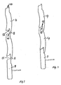
- FIG. 1 shows a detail of the guide and turning elements on one end of the curtain of the roller shutter according to the invention.
- a pulling element 20 is arranged vertically, on which the slats 4 are suspended at a predetermined distance in the swivel joint 5 such that there is a predetermined space between adjacent slats, which is covered by lower overlap edges 8 towards the outside in that the overlap edges 8 rest on the outer surface of the next lower slat 4.
- all the lamellae below are pivotably articulated in bearing bushes 22 by means of guide pins 16 which extend the upper longitudinal edge.
- an angle lever 24, 26 is fastened, one leg 24 of which runs parallel to the end face of the slats 4 and the other leg of which runs parallel to the guide pin 16 and is designed as a pin 25. All pins 25 are articulated to a coupling member 28 to form a swivel connection.
- the upper pin 25 of the angle lever 24 is extended outwards parallel to the guide pin 16 and is designed as a control element or control pin 26.
- the slats 4 have a hollow profile which is formed at the lower end as a groove profile 12, at the upper end as a spring profile 10 with the upper longitudinal edge 6.
- a wall of the guide rail in question engages between the front end 9 of the slats 4 and the angle lever 24, 25, covers the angle lever 24, 25 and the coupling member 28 and has a guide gap 52 in which the bearing bush 22 and the tension member 20 are guided.
- a control jaw 40 is arranged in a stationary manner within the guide rail 50 at a predetermined height and has a control curve which is predetermined from control sections and which interacts with the control pin 26.
- the two lateral guide rails 50 each have a control jaw 40 opposite each other at the same height, and the upper pivotable lamella carries a control pin 26 at the end at the same height.
- Fig. 2 shows a cross section through a lateral guide rail 50 with a view of the guide and coupling members of the top pivotable slat.
- the lamella 4 is closed at the end by an end cap 9.
- the guide pin 16 which is fastened by means of the bearing bushes 22 to the tension member 20 and protrudes into the guide gap 52 of the guide rail 50.
- the angle lever 24 is seated on the guide pin 16 with the control pin 26 which runs parallel to the guide pin 16 and is articulatedly coupled to the coupling member 28.
- the control jaw 40 against which the control pin 26 runs, sits on the inside of the guide rail 50 opposite the gap 52.
- the guide rail 50 is sealed against the slats 4 by means of a rubber band 56.
- the guide rail 50 consists of a two-part rail which is constructed from two angle profiles.
- a first base bracket 90 has a base 91 and an outer web 92, which starts at a right angle on the outer edge of the base.
- a cover bracket 96 with a top wall 97 and a right-angled inner web 98 is also provided.
- the base bracket 90 and the cover bracket 96 have at the free end of the outer web 92 or at the free end of the top wall 97 an interlocking clip or locking profile and can be detachably connected to one another by means of this profile.
- the latching profile of the outer web 92 contains a first latching lug 95a on its inside and continues at its end a predetermined dimension parallel to the base up to a second latching lug 95b.
- the top wall 97 of the top bracket 96 has a catch projection 99a which can be gripped behind by the catch 95b of the base bracket.
- the top wall 97 is also continued a predetermined dimension parallel to the inner web 98 to such an extent that the free end 99b engages behind the locking lug 95a. The two angles are snapped into each other before the curtain is used.
- the inner web 98 is shortened relative to the outer web 92 by the guide gap 52.
- the guide pins 16 of the lamellae run with little play in the guide gap 52, so that the cover angle 96 can no longer be detached from the base angle 90 in the case of existing guide pins 16, since the pivoting path required for this is missing.
- This embodiment of the guide rail thus combines simple assembly with a maximum of security against burglary, since access to the pulling and turning elements - after the final assembly of the roller shutter - is only possible from the outside by material destruction.
- one-piece profiles can also be used.
- the slats 4 consist of a hollow profile with open end faces.
- the end cap 9 has a plug pin 80, the cross section of which is adapted to the hollow profile of the lamella 4 and is inserted to produce a connection into the hollow profile until an end wall 82 of the end cap 9, which essentially has the shape of the lamella outer profile, against the end face of the lamella 4 rests.
- the connection between the end cap 9 and lamella 4 can be made by known connecting means, for. B. secure a snap connection or by screws etc.
- flat locking elements 84 are inserted between the plug pin 80 and the inner wall of the lamella, which are inserted at one end into an old groove 86 and carry locking lugs or barbs 88 which engage or bite into the lamella wall.
- FIG. 3 and 4 show the schematic cross section through several slats, which form the curtain shown in Fig. 1.
- Fig. 3 shows the hanging in the hanging state, in which spaces 11 form between adjacent slats 4, which are covered on the outside by overlapping edges 8.
- the upper longitudinal edge of the individual slats has a spring profile 10
- the lower longitudinal edge has a corresponding groove profile 12.
- FIG. 4 shows the cross section corresponding to FIG. 3 in the lower end position of the curtain, in which all the slats connect in a form-fitting manner, with tongue and groove profiles interlock and lock the curtain.
- the curtain ends in a lowermost slat 3, which has no profile on its lower longitudinal edge.
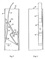
- a passage channel 42 is divided in the longitudinal direction into a rear downward track 42a and a front upward track 42b by means of a partition 41.
- a first control section 44 which is inclined outwards and downwards, is articulated to control jaws 40 with its central region. The upper end of the first control section 44 is pivotable, extends to the partition 41 and closes the upper entrance of the upward track 42b in the first position and releases this entrance in the second position.
- a third control section 43 is articulated, which runs obliquely downward against the adjacent side wall or base 91 of the guide rail 50.
- the third control section closes the downward track 42a of the flow channel in a first position and releases the downward track 42a in a second position.
- a fourth control section 47 is arranged, which in the we extends considerably upwards in the partition plane and comes to rest with the upper end - at a predetermined distance from the first control section 44 - via the upward track 42b and the first and a second control section 44a, 46.
- the first control section 44 is designed as a leaf spring, is articulated with its central region to the control jaw 40 and merges into a lower free tongue 44a which is inclined outwards and downwards with a smaller slope and is part of the second control section 44a, 46.
- a further component of the second control section 44a, 46 forms a return section 46 ; which is also directed outwards and downwards with a slight incline and forms a return channel 48 between itself and the tongue 44a, which leads back into the front upward track 42b.
- the partition 41 and the third and fourth control sections 43, 47 are integrally made of a resilient material.
- the first, the third and the fourth control section can be pressed against their own spring force from the respectively drawn first position, the closed position, into their second, unstable position, in which the corresponding tracks are open.
- the swivel assembly 5 remains in its vertical position, ie exclusively in the roller shutter function. If the front-side control element 26 is then moved upwards - together with the curtain - the control element - controlled by the third control section 43 - runs upwards through the upward track 42b, the pivoting connection therefore remaining in its vertical position. If the curtain is moved further upward along the fourth control section 47 after the control element has left the upward track 42b, the fourth control section 47 is pushed aside by the control element.
- the lamella remains Schwenkverb l rnd 5 during the entire upward movement in its vertical position (roller shutter function).
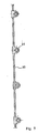
- Fig. 7 shows part of a pulling element 20 or coupling element 28 which, for. B. consists of a plastic cord high tensile strength.
- bearing bushes 22 made of plastic are injection molded along the pulling element, in which the guide pins 16 of the pivotable slats 4 are rotatably mounted.
- the bearing bushes have locking lips on the outer end, which engage in a corresponding locking groove on the free end of the guide pin.
- securing is also possible using snap rings or the like.
- the distance between two bearing bushes is dimensioned such that the pivotable lamellae mounted therein hang freely from one another and can carry out a pivoting movement without being disturbed. If the tension members 20 are relieved and the lamellae are seated on one another, the distance between adjacent bearing bushes 22 is shortened accordingly.
- the traction element shown can also consist of a wire strand or the like.
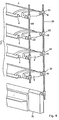
- FIG. 8 shows a partial view of the lamella composite 5, the lamellae 4 of which are connected to tension elements 20 and coupling elements 28 according to FIG. 7. At the lower end of the tension member 20, the end lamella 15 is arranged in a rotationally secure manner.
- FIG. 9 shows a cross section through the lower end lamella and a few pivotable lamellae 4 above it.
- a hanging element 80 is fastened to the lamellae in the region of the upper longitudinal edge between the pulling elements guided on the ends of the lamellae.
- the hanging organ 80 consists, for. B. from a cord, a band of textile, plastic material or metal.
- the slats 4 have in the region of their upper longitudinal edge a longitudinal groove 82 in the connecting elements, for. B. detent springs are insertable and on the hanging organ - z. B. by means of connecting loops.
- the hanging elements are attached to the upper winding drum of the roller shutter and are intended to prevent the slats 4 from sagging.
- the slats a single-shell profile which has an interlocking locking profile on the upper and lower vertical edges for receiving the. speaking vertical edge of the adjacent slat.
Landscapes
- Engineering & Computer Science (AREA)
- Structural Engineering (AREA)
- Architecture (AREA)
- Civil Engineering (AREA)
- Operating, Guiding And Securing Of Roll- Type Closing Members (AREA)
- Blinds (AREA)
Description
- Die Erfindung betrifft einen Rolladen mit einem Behang aus horizontalen Lamellen, die an ihren Stirnkanten mit Führungszapfen in vertikalen Führungsschienen zwischen einer oberen Endlage und einer unteren Endlage führbar sind und ab einer vorgegebenen oberen Lamelle schwenkbar an Zugorganen aufgehängt und mit Koppelorganen zu einem Lamellenschwenkverbund aus mehreren parallelen ausschwenkbaren Lamellen verbunden sind, mit Steuerabschnitten an Steuerbacken, die beim Verfahren des Rolladens mit stirnseitigen Steuerelementen des Lamellenschwenkverbundes in Eingriff gelangen und den Lamellenschwenkverbund wahlweise aus einer Vertikalstellung in eine Schwenkstellung steuern, wobei die Steuerbacken einen mittels einer Trennwand in Längsrichtung in eine hintere Abwärtsspur und eine vordere Aufwärtsspur geteilten Durchlaufkanal, einen ersten auswärts und abwärts geneigten Steuerabschnitt, einen daran anschließenden im wesentlichen horizontalen zweiten Steuerabschnitt, einen schräg nach hinten abwärts verlaufenden dritten Steuerabschnitt am unteren Ende der Trennwand, und einen schräg nach vorn aufwärts verlaufenden vierten Steuerabschnitt am oberen Ende der Trennwand enthalten, und wobei das obere Ende des ersten Steuerabschnitts bis zur Trennwand verläuft und die Aufwärtsspur in einer ersten Stellung schließt und in einer zweiten Stellung freigibt.
- Ein derartiger Rolladen ist aus der DE-B-1 266 475 bekannt, bei dem die Abwärtsspur der Steuerbacken innerhalb der Führungsschiene, die Aufwärtsspur dagegen außerhalb der Führungsschiene in einem auf die Führungsschiene aufgesetzten Steuerbackenteil verlaufen. Beim Absenken des Rolladen laufen die stirnseitigen Steuerelemente des Lamellenschwenkverbundes in der Abwärtsspur. Beim Hochfahren des Rolladen wechseln die Steuerelemente in die Aufwärtsspur über und können dann aus dieser Position heraus - durch erneutes Absenken - in die Schwenkstellung übergehen, in welcher der Lamellenschwenkverbund als Jalousie wirkt, welche zwischen den ausgeschwenkten Lamellen indirektes Licht hindurchtreten läßt, die direkte Sonneneinstrahlung jedoch wirksam verhindert. Bei einem erneuten Anheben des Behangs aus der Schwenkstellung durchlaufen die Steuerelemente des Lamellenschwenkverbundes die Aufwärtsspur und wechseln dann wieder zurück in die Abwärtsspur, welche mit der Spur der Führungsschiene fluchtet. Der Wechsel der Steuerelemente von der Abwärtsspur in die Aufwärtsspur erfolgt unter Wirkung von Federmechaniken und/oder besonderer Formgebung der Steuerelemente, die bei Aufwärtsbewegung vom dritten Steuerabschnitt am unteren Ende der Trennwand in die Aufwärtsspur eingeleitet werden sollen. Dabei lassen sich Fehlsteuerungen oder Verkantungen der Steuerelemente am Einlaß in die Aufwärtsspur nicht sicher vermeiden.
- Aus der DE-B-1 260 113 ist ebenfalls ein Rolladen bekannt, bei dem ein Lamellenschwenkverbund bei Abwärtsbewegung als Rolladen geführt ist und bei einer Aufwärtsbewegung in eine Schwenkstellung, d. h. eine Jalousiestellung übergeht. Auf die Führungsschienen sind Steuerbacken aufgesetzt, welche lediglich einen nach abwärts und außen gerichteten Steuerabschnitt enthält, der mittels eines Sperriegels bei einer Abwärtsbewegung des Behangs für die Steuerelemente verschlossen ist, und bei einer Aufwärtsbewegung für die Steuerelemente geöffnet wird, so daß diese bei einem Absenken nach vorausgegangenem kurzen Anheben in diesen Steuerabschnitt einlaufen und den Lamellenschwenkverbund in die Schwenkstellung führen. Nachteilig ist hierbei ebenfalls, daß der Sperriegel sich leicht verklemmen kann, so daß es zu Fehlsteuerungen oder einer Blockage der Steuerelemente kommen kann.
- Aufgabe der Erfindung ist es demgegenüber, einen Rolladen der eingangs genannten Art derart weiterzubilden, daß die wahlweise Steuerung des Lamellenschwenkverbunds in die Vertikalstellung (Rolladenstellung) oder die Schwenkstellung (Jalousiestellung) in einfacher Weise zuverlässig durchführbar ist.
- Diese Aufgabe wird erfindungsgemäß dadurch gelöst, daß die Steuerbacken in den Führungsschienen so angeordnet sind, daß der Durchlaufkanal in der Ebene der Führungszapfen verläuft, und daß der dritte Steuerabschnitt zur Basis der Führungsschiene verlängert ist und die Abwärtsspur in einer ersten Stellung schließt und in einer zweiten Stellung freigibt, und daß der vierte Steuerabschnitt sich in einer ersten Stellung über die Aufwärtsspur erstreckt und diese schließt, und in einer zweiten Stellung die Aufwärtsspur freigibt.
- Die Vorteile der Erfindung liegen insbesondere darin, daß die Steuerbacken in den Führungsschienen so angeordnet werden, daß sowohl die Abwärtsspur als auch die Aufwärtsspur in der Ebene der Führungszapfen verläuft, und daß die Abwärtsspur an ihrem unteren Ende für aufwärts laufende Steuerelemente zuverlässig verschlossen, die Aufwärtsspur dagegen breit geöffnet ist, so daß der Wechsel der stirnseitigen Steuerelemente des Lamellenschwenkverbundes von der Abwärtsspur in die Aufwärtsspur, in welcher dann die Steuerelemente - bei erneutem Absenken - in die Schwenkstellung gehen können, ohne Fehlsteuerungen durchführbar ist. Beim Absenken des Behanges ist dagegen die Abwärtsspur breit geöffnet, während die Aufwärtsspur für die Steuerelemente des Lamellenschwenkverbundes zuverlässig geschlossen ist. Beim Absenken aus dem aufgewickelten Zustand verbleibt daher der Behang zuverlässig in seiner Vertikalstellung, Ein Übergang in die Schwenkstellung, in welcher die Steuerelemente auf dem zweiten Steuerabschnitt der Steuerbacken ruhen, ist nur nach vorausgegangener Aufwärtsbewegung möglich. Fehlsteuerungen werden zuverlässig vermieden.
- Gemäß einer bevorzugten Ausführungsform der Erfindung ist der zweite Steuerabschnitt in eine am ersten Steuerabschnitt sitzende Zunge sowie einen separaten Rücklaufabschnitt geteilt. Zwischen Zunge und dem Rücklaufabschnitt befindet sich ein Rücklaufkanal, durch den die Steuerelemente, wenn sie sich im vorderen Bereich des Rücklaufabschnitts, nämlich in der Schwenkstellung, befinden, direkt in den unteren Bereich der Aufwärtsspur eintreten können. Anschließend läßt sich der Behang wahlweise aufwärts oder abwärts bewegen, wodurch die Flexibilität der Steuerfunktionen erhöht ist.
- Die Führungsschienen besitzen bevorzugt einen möglichst geschlossenen Querschnitt, der lediglich zur Stirnseite der Lamellen hin geöffnet ist und einen Führungsspalt aufweist, in dem die Führungszapfen geführt werden. Ein derartiges Profil der Führungsschiene wird bevorzugt aus zwei Teilschienen, einem Basiswinkel und einem Deckwinkel zusammengesetzt. Der Basiswinkel besitzt eine Basis, die parallel zur Behangebene angebracht wird, sowie einen Außensteg rechtwinklig an der Außenkante der Basis. Der Deckwinkel besitzt eine Deckwand parallel zur Basis sowie einen Innensteg parallel zum Außensteg. Zwischen Basis und Innensteg befindet sich der Führungsspalt. Erfindungsgemäß befindet sich am freien Ende des Außenstegs sowie am freien Ende der Deckwand ein sich entsprechendes Clip-Profil, und der Deckwinkel wird vor der Montage des Behangs an den Basiswinkel angeclipst. Die Führungszapfen der Lamellen werden im Führungsspalt mit relativ geringem Spiel geführt. Nach dem Einführen der Führungszapfen in den Führungsspalt der Führungsschiene fehlt daher im Führungsspalt der zum Lösen der Clipverbindung erforderliche Weg. Die Clipverbindung ist daher nach Einführen des Behangs nur durch Materialzerstörung lösbar und stellt somit eine Einbruchsicherung dar, da die Zugorgane gegen Zerstörung sicher geschützt sind.
- Gegenüberliegende Längsseiten benachbarter Lamellen sind bevorzugt mit einem Nutprofil und einem entsprechenden Federprofil ausgebildet, die bei gegenseitiger Abstützung der Lamellen ineinandergreifen und den Behang wirksam verriegeln. Bevorzugt besitzt das Nutprofil am unteren Ende der Lamellen außerdem eine außenliegende Überlappungskante, die sich außen über die obere Längskante der darunter hängenden Lamelle legt und den Zwischenraum auch bei frei hängenden Lamellen abdeckt.
- Die Zugorgane und die Koppelorgane sind bevorzugt als Kunststoff- oder Metallschnur ausgebildet und tragen in vorgegebenem Abstand voneinander Lagerbuchsen. Die schwenkbaren Lamellen besitzen in Verlängerung der oberen Längskante Führungszapfen, die drehbar in den Lagerbuchsen an den Zugorganen gelagert sind und zusammen mit den Zugorganen in den Führungsspalten der Führungsschiene laufen. Die Lagerbuchsen sind bevorzugt als Kunststoff-Formteil angespritzt und besitzen zur axialen Festlegung der Führungszapfen bevorzugt Rastelemente, die in entsprechende Rastnuten der Führungszapfen greifen.
- Weiterbildungen der Erfindung sind durch die Merkmale der Unteransprüche gekennzeichnet.
- Im folgenden werden Ausführungsbeispiele der Erfindung anhand der Zeichnung näher erläutert. Es zeigen :
- Figur 1 eine perspektivische Ansicht einer ersten Ausführungsform der seitlichen Führungs-und Steuerorgane des erfindungsgemäßen Rolladens ;
- Figur 2 einen Querschnitt durch eine seitliche Führungsschiene des Rolladens gemäß Fig. 1 ;
- Figuren 3 und 4 einen Querschnitt durch die unteren Lamellen eines erfindungsgemäßen Rolladen-Behangs in hängendem bzw. aufgesetztem Zustand ;
- Figuren 5 und 6 zwei Ansichten des Steuerbackens ;
- Figuren 7 und 8 eine Ausführungsform eines Zug- oder Koppelorgans und den entsprechend gehängten Lamellenverbund ;
- Figur 9 einen Querschnitt durch eine schwenkbare Lamelle, der die Anbringung eines Hängeorgans auf der Rückseite der Lamellen zeigt.
- Fig. 1 zeigt in einem Ausschnitt die Führungs-und Wendeorgane an einer Stirnseite des Behangs des erfindungsgemäßen Rolladens. An den Stirnseiten des Behangs ist je ein Zugorgan 20 vertikal angeordnet, an dem die Lamellen 4 in vorgegebenem Abstand im Schwenkverbund 5 derart aufgehängt sind, daß zwischen benachbarten Lamellen ein vorgegebener Zwischenraum besteht, der von unteren Überlappungskanten 8 nach außen hin dadurch verdeckt wird, daß die Überlappungskanten 8 auf der Außenoberfläche der nächstunteren Lamelle 4 aufliegen. Ab einer vorgegebenen oberen Lamelle 4 sind alle darunterliegenden Lamellen mittels die obere Längskante verlängernde Führungszapfen 16 schwenkbar in Lagerbuchsen 22 angelenkt. Am äußeren Ende des Führungszapfens 16 ist ein Winkelhebel 24, 26 befestigt, dessen einer Schenkel 24 parallel zur Stirnseite der Lamellen 4, und dessen anderer Schenkel parallel zum Führungszapfen 16 verläuft und als Stift 25 ausgebildet ist. Alle Stifte 25 sind gelenkig mit einem Koppelorgan 28 zu einem Schwenkverbund verbunden. Der obere Stift 25 des Winkelhebels 24 ist parallel zum Führungszapfen 16 auswärts verlängert und als Steurelement oder Steuerstift 26 ausgebildet. Die Lamellen 4 besitzen ein Hohlprofil, das am unteren Ende als Nutprofil 12, am oberen Ende als Federprofil 10 mit der oberen Längskante 6 ausgebildet ist.
- Zwischen das Stirnende 9 der Lamellen 4 und den Winkelhebel 24, 25 greift eine Wand der betreffenden Führungsschiene ein, deckt die Winkelhebel 24, 25 sowie das Koppelorgan 28 ab und besitzt einen Führungsspalt 52, in dem die Lagerbuchse 22 und das Zugorgan 20 geführt sind.
- Innerhalb der Führungsschiene 50 ist in vorgegebener Höhe ein Steuerbacken 40 stationär angeordnet und besitzt eine aus Steuerabschnitten vorgegebene Steuerkurve, die mit dem Steuerstift 26 zusammenwirkt. Die beiden seitlichen Führungsschienen 50 tragen in gleicher Höhe einander gegenüberliegend je einen Steuerbacken 40, und die obere schwenkbare Lamelle trägt stirnseitig in derselben Höhe je einen Steuerstift 26.
- Fig. 2 zeigt einen Querschnitt durch eine seitliche Führungsschiene 50 mit einer Aufsicht auf die Führungs- und Koppelorgane der obersten schwenkbaren Lamelle. Die Lamelle 4 ist stirnseitig durch eine Endkappe 9 abgeschlossen. An der oberen Längskante setzt stirnseitig der Führungszapfen 16 an, der mttels der Lagerbuchsen 22 an dem Zugorgan 20 befestigt ist und in den Führungsspalt 52 der Führungsschiene 50 hineinragt. Am Führungszapfen 16 sitzt der Winkelhebel 24 mit dem parallel zum Führungszapfen 16 verlaufenden Steuerstift 26, der gelenkig mit dem Koppelorgan 28 gekoppelt ist. An der dem Spalt 52 gegenüberliegenden Innenseite der Führungsschiene 50 sitzt der Steuerbacken 40, gegen den der Steuerstift 26 anläuft. Die Führungsschiene 50 ist mittels eines Gummibandes 56 gegen die Lamellen 4 abgedichtet.
- Die Führungsschiene 50 besteht in der dargestellten Ausführungsform aus einer zweiteiligen Schiene, die aus zwei Winkelprofilen aufgebaut ist. Ein erster Basiswinkel 90 besitzt eine Basis 91 und einen an der Außenkante der Basis rechtwinklig ansetzenden Außensteg 92. Vorgesehen ist ferner ein Deckwinkel 96 mit einer Deckwand 97 und einem rechtwinklig ansetzenden Innensteg 98. Der Basiswinkel 90 und der Deckwinkel 96 besitzen am freien Ende des Außenstegs 92 bzw. am freien Ende der Deckwand 97 ein ineinandergreifendes Clip- oder Rastprofil und lassen sich mittels dieses Profils lösbar miteinander verbinden. Das Rastprofil des Außenstegs 92 enthält an seiner Innenseite eine erste Rastnase 95a und setzt sich an seinem Ende ein vorgegebenes Maß parallel zur Basis bis zu einer zweiten Rastnase 95b fort. Die Deckwand 97 des Deckwinkels 96 besitzt einen Rastansatz 99a, der von der Rastnase 95b des Basiswinkels hintergreifbar ist. Die Deckwand 97 ist ferner ein vorgegebenes Maß parallel zum Innensteg 98 soweit fortgesetzt, daß das freie Ende 99b hinter die Rastnase 95a greift. Die beiden Winkel werden vor Einsatz des Behangs ineinander eingerastet.
- Der Innensteg 98 ist gegenüber dem Außensteg 92 um den Führungsspalt 52 verkürzt. Die Führungszapfen 16 der Lamellen laufen mit geringem Spiel im Führungsspalt 52, so daß der Deckwinkel 96 bei vorhandenen Führungszapfen 16 von dem Basiswinkel 90 nicht mehr gelöst werden kann, da der hierfür erforderliche Schwenkweg fehlt. Diese Ausführungsform der Führungsschiene vereinigt somit eine einfache Montierbarkeit mit einem Höchstmaß an Einbruchsicherheit, da der Zugang zu den Zug- und Wendeorganen - nach der Endmontage des Rolladens - von außen nur durch eine Materialzerstörung möglich ist. Alternativ lassen sich auch einstückige Profile einsetzen. Die Lamellen 4 bestehen aus einem Hohlprofil mit offenen Stirnseiten. Die Endkappe 9 besitzt einen Steckzapfen 80, dessen Querschnitt an das Hohlprofil der Lamelle 4 angepaßt ist und zur Herstellung einer Verbindung in das Hohlprofil soweit eingesteckt wird, bis eine Endwand 82 der Endkappe 9, die im wesentlichen die Form des Lamellen-Außenprofils besitzt, gegen die Stirnfläche der Lamelle 4 anliegt. Die Verbindung zwischen Endkappe 9 und Lamelle 4 läßt sich durch an sich bekannte Verbindungsmittel, z. B. eine Rastverbindung oder durch Schrauben etc. sichern. In der dargestellten Ausführungsform sind zwischen dem Steckzapfen 80 und der Innenwand der Lamelle ebene Rastelemente 84 zwischengefügt, die mit einem Ende in eine alte Nut 86 eingesteckt sind und Rastnasen oder Widerhaken 88 tragen, die sich in der Lamellenwand einrasten oder festbeißen.
- Die Fig. 3 und 4 zeigen den schematischen Querschnitt durch mehrere Lamellen, die den in Fig. 1 dargestellten Behang bilden. Fig. 3 zeigt den Behang in hängendem Zustand, in dem sich Zwischenräume 11 zwischen benachbarten Lamellen 4 bilden, die nach außen hin durch Überlappkanten 8 verdeckt sind. Die obere Längskante der einzelnen Lamellen besitzt ein Federprofil 10, die untere Längskante ein entsprechendes Nutprofil 12. Fig. 4 zeigt den der Fig. 3 entsprechenden Querschnitt in der unteren Endlage des Behangs, in der alle Lamellen sich formschlüssig verbinden, wobei Nut- und Federprofile ineinander greifen und den Behang verriegeln. Der Behang endet in einer untersten Lamelle 3, die an ihrer unteren Längskante kein Profil besitzt.
- Die Fig. 5 und 6 zeigen eine Seitenansicht und eine Vorderansicht des Steuerbackens 40 in der Führungsschiene 50. Ein Durchlaufkanal 42 ist mittels einer Trennwand 41 in Längsrichtung in eine hintere Abwärtsspur 42a und eine vordere Aufwärtsspur 42b geteilt. Ein erster Steuerabschnitt 44, der auswärts und abwärts geneigt ist, ist mit seinem mittleren Bereich an Steuerbacken 40 angelenkt. Das obere Ende des ersten Steuerabschnitts 44 ist schwenkbar, reicht bis zur Trennwand 41 und schließt den oberen Eingang der Aufwärtsspur 42b in der ersten Stellung und gibt diesen Eingang in der zweiten Stellung frei. Am unteren Ende der Trennwand 41 ist ein dritter Steuerabschnitt 43 angelenkt, der schräg abwärts gegen die benachbarte Seitenwand oder Basis 91 der Führungsschiene 50 läuft. Der dritte Steuerabschnitt schließt in einer ersten Stellung die Abwärtsspur 42a des Durchlaufkanals, und gibt in einer zweiten Stellung die Abwärtsspur 42a frei. Am oberen Ende der Trennwand 41 ist ein vierter Steuerabschnitt 47 angeordnet, der sich im wesentlichen in der Trennwandebene nach oben erstreckt und mit dem oberen Ende - in vorgegebenem Abstand von dem ersten Steuerabschnitt 44 - über die Aufwärtsspur 42b und den ersten und einen zweiten Steuerabschnitt 44a, 46 zu liegen kommt.
- Der erste Steuerabschnitt 44 ist als Blattfeder ausgebildet, ist mit seinem mittleren Bereich am Steuerbacken 40 angelenkt und geht in eine untere freie Zunge 44a über, die mit geringerer Steigung auswärts und abwärts geneigt ist und Bestandteil des zweiten Steuerabschnitts 44a, 46 ist. Einen weiteren Bestandteil des zweiten Steuerabschnitts 44a, 46 bildet ein Rücklaufabschnitt 46; der ebenfalls mit geringer Steigung auswärts und abwärts gerichtet ist und zwischen sich und der Zunge 44a einen Rücklaufkanal 48 bildet, der in die vordere Aufwärtsspur 42b zurückführt.
- Die Trennwand 41 und der dritte und vierte Steuerabschnitt 43, 47 bestehen integral aus einem federelastischen Material. Der erste, der dritte und der vierte Steuerabschnitt lassen sich bei Krafteinwirkung gegen ihre eigene Federkraft aus der jeweils eingezeichneten ersten Stellung, der Schließstellung, in ihre zweite, labile Stellung drücken, in der die entsprechenden Spuren geöffnet sind.
- Ein durchgängig - mit dem Behang - abwärts geführtes stirnseitiges Steuerelement 26 wird daher von dem vierten Steuerabschnitt 47 in die Abwärtsspur 42a geführt, tritt aus der Abwärtsspur 42a in vertikaler Richtung aus und drückt dabei den dritten Steuerabschnitt 43 kurzzeitig in dessen zweite Stellung. Bei einer durchgängigen Abwärtsbewegung bleibt der Schwenkverbund 5 in seiner Vertikalstellung d. h. ausschließlich in Rolladenfunktion. Wird anschließend das stirnseitige Steuerelement 26 - zusammen mit dem Behang - aufwärts bewegt, so läuft das Steuerelement - vom dritten Steuerabschnitt 43 gesteuert - durch die Aufwärtsspur 42b nach oben, der Schwenkverbund verbleibt daher in seiner Vertikalstellung. Wird der Behang nach dem Austritt des Steuerelementes aus der Aufwärtsspur 42b längs des vierten Steuerabschnitts 47 weiter aufwärts bewegt, so wird der vierte Steuerabschnitt 47 durch das Steuerelement zur Seite gedrückt. Der Lamellen-Schwenkverblrnd 5 bleibt während der gesamten Aufwärtsbewegung in seiner Vertikalstellung (Rolladenfunktion).
- Kommt dagegen das stirnseitige Steuerelement nach Verlassen der Aufwärtsspur 42b zur Ruhe, d. h. bleibt das Steuerelement 26 zwischen erstem Steuerabschnitt 44 und viertem Steuerabschnitt 47, und erfolgt dann eine zweite Abwärtsbewegung, so gleitet das Steuerelement längs des ersten Steuerabschnitts 44 auf den zweiten Steuerabschnitt 44a, 46, nämlich auf die horizontale untere Zunge 44a und anschließend auf den Rücklaufabschnitt 46. Das Steuerelement 26 und der Lamellen-Schwenkverbund befinden sich dann in ihrer Schwenkstellung (Jalousiefunktion). Durch eine anschließende erneute Aufwärtsbewegung des Behangs gleitet das Steuerelement durch den Rücklaufkanal 48, die Aufwärtsspur 42b, am vierten Steuerabschnitt 47 vorbei nach oben und nimmt nach Verlassen des Rücklaufkanals 48 wieder die Vertikalstellung (Rolladenfunktion) ein.
- Fig. 7 zeigt einen Teil eines Zugorgans 20 oder Koppelorgans 28, das z. B. aus einer Kunststoffschnur hoher Zugfestigkeit besteht. In vorgegebenem Abstand sind längs des Zugorgans 20 Lagerbuchsen 22 aus Kunststoff angespritzt, in denen die Führungszapfen 16 der schwenkbaren Lamellen 4 drehbar gelagert sind. Zur axialen Festlegung der Führungszapfen 16 besitzen die Lagerbuchsen an dem außen liegenden Ende Rastlippen, die in eine entsprechende Rastnut am freien Ende der Führungszapfen eingreifen. Alternativ ist die Sicherung auch durch Sprengringe od. dgl. möglich. Der Abstand zwischen zwei Lagerbuchsen ist so bemessen, daß die darin gelagerten schwenkbaren Lamellen untereinander frei hängen und ungestört eine Schwenkbewegung ausführen können. Wenn die Zugorgane 20 entlastet werden und die Lamellen aufeinander aufsitzen, verkürzt sich der Abstand zwischen benachbarten Lagerbuchsen 22 entsprechend. Anstelle einer Kunststoffschnur kann das dargestellte Zugorgan auch aus einer Drahtlitze od. dgl. bestehen.
- Fig. 8 zeigt eine Teilansicht des Lamellenverbunds 5, dessen Lamellen 4 mit Zugorganen 20 und Koppelorganen 28 gemäß Fig. 7 verbunden sind. Am unteren Ende des Zugorgans 20 ist die Endlamelle 15 verdrehsicher angeordnet.
- Fig. 9 zeigt einen Querschnitt durch die untere Endlamelle und einigen darüberliegenden schwenkbaren Lamellen 4. Auf der Rückseite der Lamelle ist - zwischen den an den Lamellen-Stirnseiten geführten Zugorganen - ein Hängeorgan 80 an den Lamellen im Bereich der oberen Längskante befestigt. Das Hängeorgan 80 besteht z. B. aus einer Schnur, einem Band aus Textil-, Kunststoff-Material oder aus Metall. Die Lamellen 4 besitzen im Bereich ihrer oberen Längskante eine Längsnut 82, in die Verbindungselemente, z. B. Rastfedern, einführbar sind und am Hängeorgan - z. B. mittels Verbindungsschlaufen - befestigt werden. Die Hängeorgane sind an der oberen Wickeltrommel des Rolladens befestigt und sollen einen Durchhang der Lamellen 4 verhindern.
- Alternativ ist es auch möglich, den Lamellen ein einschaliges Profil zu verleihen, welches an den oberen und unteren Vertikalkanten ein ineinandergreifendes Rastprofil zur Aufnahme der ent- . sprechenden Vertikalkante der benachbarten Lamelle besitzt.
Claims (16)
Priority Applications (3)
| Application Number | Priority Date | Filing Date | Title |
|---|---|---|---|
| AT82110244T ATE25126T1 (de) | 1979-07-21 | 1980-07-11 | Rolladen. |
| AT80104012T ATE7067T1 (de) | 1979-07-21 | 1980-07-11 | Rolladen. |
| DE8282110244T DE3071893D1 (en) | 1979-07-21 | 1980-07-11 | Roller shutter |
Applications Claiming Priority (2)
| Application Number | Priority Date | Filing Date | Title |
|---|---|---|---|
| DE19792929675 DE2929675A1 (de) | 1979-07-21 | 1979-07-21 | Rolladen |
| DE2929675 | 1979-07-21 |
Related Child Applications (1)
| Application Number | Title | Priority Date | Filing Date |
|---|---|---|---|
| EP82110244.9 Division-Into | 1982-11-06 |
Publications (2)
| Publication Number | Publication Date |
|---|---|
| EP0023974A1 EP0023974A1 (de) | 1981-02-18 |
| EP0023974B1 true EP0023974B1 (de) | 1984-04-11 |
Family
ID=6076445
Family Applications (2)
| Application Number | Title | Priority Date | Filing Date |
|---|---|---|---|
| EP80104012A Expired EP0023974B1 (de) | 1979-07-21 | 1980-07-11 | Rolladen |
| EP82110244A Expired EP0081672B1 (de) | 1979-07-21 | 1980-07-11 | Rolladen |
Family Applications After (1)
| Application Number | Title | Priority Date | Filing Date |
|---|---|---|---|
| EP82110244A Expired EP0081672B1 (de) | 1979-07-21 | 1980-07-11 | Rolladen |
Country Status (2)
| Country | Link |
|---|---|
| EP (2) | EP0023974B1 (de) |
| DE (3) | DE2929675A1 (de) |
Cited By (1)
| Publication number | Priority date | Publication date | Assignee | Title |
|---|---|---|---|---|
| DE102005037775B4 (de) * | 2005-08-10 | 2012-11-08 | Roma Kg | Jalousierbarer Rollladen |
Families Citing this family (22)
| Publication number | Priority date | Publication date | Assignee | Title |
|---|---|---|---|---|
| DE3101548A1 (de) * | 1981-01-20 | 1982-09-23 | Justin Hüppe GmbH, 2900 Oldenburg | Rolladen |
| DE3313467A1 (de) * | 1983-04-14 | 1984-10-25 | Max H. Dr.-Ing. 7024 Filderstadt Losch | Lamellen-laden |
| DE3437346A1 (de) * | 1983-10-14 | 1985-05-23 | Gradhermetic, S.A.E., Tarrasa, Barcelona | Aufrollbare abschirmung |
| DE3408177C1 (de) * | 1984-03-06 | 1985-06-20 | Helmut Ing.(grad.) 7847 Badenweiler Rathmann | Rolladenjalousie |
| DE3412480C2 (de) * | 1984-04-03 | 1987-01-29 | Nixdorf Computer Ag, 4790 Paderborn | Jalousieverschluß |
| DE3501689A1 (de) * | 1985-01-19 | 1986-07-24 | Helmut Ing.(grad.) 7847 Badenweiler Rathmann | Rolladenjalousie |
| GB8906967D0 (en) * | 1989-03-28 | 1989-05-10 | Leisk Colin A | Convertible shutter/blind |
| IL109652A (en) * | 1994-05-15 | 1997-06-10 | Yedidia Hagai | Louvered movable window shutter |
| ES2133024B1 (es) * | 1995-07-20 | 2000-03-16 | Gradhermetic Ind | Persiana arrollable de lamas orientables. |
| DE19601613C2 (de) * | 1996-01-18 | 1999-04-15 | Bruno Kiefer | Rolladen mit ausschwenkbaren Lamellen |
| AT403829B (de) * | 1996-05-02 | 1998-05-25 | Famulus Elektrogeraete Gmbh | Jalousierbarer rolladen |
| AT403830B (de) * | 1996-10-07 | 1998-05-25 | Famulus Elektrogeraete Gmbh | Jalousierbarer rolladen |
| WO1998031910A2 (de) * | 1997-01-20 | 1998-07-23 | Uwe Steinleitner | Jalousierbarer rolladen |
| AT406701B (de) | 1998-05-27 | 2000-08-25 | Famulus Elektrogeraete Gmbh | Lamelle für läden, z.b. rolläden |
| ES2196936B1 (es) * | 2000-10-27 | 2005-03-01 | Ramon Casals Artigas | Sistema posicionador de lamas oreintables en persianas enrollables. |
| DE102005037756B4 (de) * | 2005-08-10 | 2013-07-11 | Roma Kg | Rollladenbehang |
| ES2310082B1 (es) * | 2006-03-15 | 2009-10-26 | Industrial Gradhermetic S.A.E. | Cadena para persiana arrollable. |
| DE202011050684U1 (de) * | 2011-07-11 | 2012-07-12 | Vera Schöne | Rollladen zum Verschluss eines Fensters einer Tür oder dergleichen |
| DE102012007141A1 (de) | 2012-04-10 | 2013-10-10 | Bernhard Spindler | Jalousierbarer Rollladenpanzer |
| ES2525266B1 (es) * | 2013-06-19 | 2015-09-24 | Industrial Gradhermetic S.A.E. | Persiana de lamas apilables y orientables |
| DE102013108663A1 (de) | 2013-08-09 | 2015-02-12 | Heroal - Johann Henkenjohann Gmbh & Co. Kg | Jalousierbarer Rollladenpanzer mit schwenkbaren Stäben |
| IL280916B2 (en) * | 2021-02-16 | 2023-02-01 | G T A Motors Ltd | Roller shutter with tilting slats and synchronized tilting unit |
Family Cites Families (13)
| Publication number | Priority date | Publication date | Assignee | Title |
|---|---|---|---|---|
| DE7413039U (de) * | 1974-07-18 | Vki Rheinhold & Mahla Ag | Rolladen, insbesondere für Fenster | |
| DE27821C (de) * | H. LANDWEHR i«1 Stuttgart, Friedrichstr. 53 | Rollläden mit drehbaren Stäbef | ||
| CH328342A (de) * | 1953-09-01 | 1958-03-15 | Colom Grau Jaime | Rolladen |
| DE1260113B (de) * | 1958-02-15 | 1968-02-01 | Jaime Colom Grau | Einrichtung zum jalousieartigen Verstellen von Rolladenstaeben |
| DE1509213A1 (de) * | 1963-01-22 | 1969-06-26 | Hunter Douglas | Lamellen-Rolladen |
| FR1364656A (fr) * | 1963-05-06 | 1964-06-26 | Fermetures Mischler | Volet roulant à lames orientables |
| DE1890778U (de) * | 1964-01-25 | 1964-04-09 | Charlotte Nawrath | Rollladen aus kunststoff. |
| ES296295A1 (es) * | 1964-02-10 | 1964-04-01 | Colom Grau Jaime | Dispositivo de basculaciën para persianas arrollables de tablillas basculantes y graduables |
| DE1928212U (de) * | 1965-10-14 | 1965-12-02 | Adolf Donat | Rolladen mit ausstellbaren lamellen. |
| LU52888A1 (de) * | 1966-02-15 | 1967-03-28 | ||
| AT293704B (de) * | 1968-07-26 | 1971-10-25 | Elastofol Isolier Und Schutzvo | Schattendecken für Gewächshäuser |
| FR2130884A5 (de) * | 1971-03-24 | 1972-11-10 | Maine Plastiques | |
| CH560834A5 (de) * | 1972-12-27 | 1975-05-15 | Schenker Emil Storen Und Masch |
-
1979
- 1979-07-21 DE DE19792929675 patent/DE2929675A1/de not_active Ceased
-
1980
- 1980-07-11 DE DE8080104012T patent/DE3067428D1/de not_active Expired
- 1980-07-11 DE DE8282110244T patent/DE3071893D1/de not_active Expired
- 1980-07-11 EP EP80104012A patent/EP0023974B1/de not_active Expired
- 1980-07-11 EP EP82110244A patent/EP0081672B1/de not_active Expired
Cited By (1)
| Publication number | Priority date | Publication date | Assignee | Title |
|---|---|---|---|---|
| DE102005037775B4 (de) * | 2005-08-10 | 2012-11-08 | Roma Kg | Jalousierbarer Rollladen |
Also Published As
| Publication number | Publication date |
|---|---|
| EP0023974A1 (de) | 1981-02-18 |
| DE3071893D1 (en) | 1987-02-26 |
| EP0081672A1 (de) | 1983-06-22 |
| EP0081672B1 (de) | 1987-01-21 |
| DE3067428D1 (en) | 1984-05-17 |
| DE2929675A1 (de) | 1981-01-29 |
Similar Documents
| Publication | Publication Date | Title |
|---|---|---|
| EP0023974B1 (de) | Rolladen | |
| DE69519764T2 (de) | Jalousierbarer Rolladen | |
| DE69705495T2 (de) | Fensterabdeckung | |
| DE69723114T2 (de) | Rolltor mit reibungsarmen randbereichen | |
| DE69839138T2 (de) | Store oder Jalousie für ein Fenster | |
| DE3501689C2 (de) | ||
| EP0382172A2 (de) | Jalousierbarer Rolladen | |
| DE2947501A1 (de) | Ein- und ausfahrbare abdeckvorrichtung, insbesondere rolladen fuer fenster, tueren, tore o.dgl. | |
| DE2623359C3 (de) | Verschlußvorrichtung für Wandöffnungen o.dgl | |
| DE3101548A1 (de) | Rolladen | |
| DE69606561T2 (de) | Abschirmvorrichtung | |
| DE9190032U1 (de) | Fenster mit Abschattungselement | |
| DE3837410A1 (de) | Rolladen aus kastenfoermigen rolladenstaeben und verbindungsstaeben mit c-foermigem querschnitt | |
| DE19805272B4 (de) | Einrichtung zum Schützen, Abdecken, Verschließen, Abtrennen o. dgl. Abgrenzen von Bereichen | |
| EP0093695B1 (de) | Rolljalousie und Anhaltevorrichtung für die sich abwärts bewegende Rolljalousie | |
| WO2023139238A1 (de) | Rollladenstab und rollladen | |
| AT406701B (de) | Lamelle für läden, z.b. rolläden | |
| DE2653349C3 (de) | Lamellenjalousie für Fenster o.dgl. | |
| DE19848944C1 (de) | Rolladenpanzer | |
| DE2301752A1 (de) | Jalousie | |
| DE3408177C1 (de) | Rolladenjalousie | |
| DE10236869A1 (de) | Raffstore mit Wendelager | |
| DE60203062T2 (de) | Verschlusseinrichtung | |
| DE20305389U1 (de) | Vorrichtung zum Verbinden eines Rollvorhangs mit einer Wickelwelle | |
| AT398458B (de) | Jalousierbarer rolladen |
Legal Events
| Date | Code | Title | Description |
|---|---|---|---|
| PUAI | Public reference made under article 153(3) epc to a published international application that has entered the european phase |
Free format text: ORIGINAL CODE: 0009012 |
|
| AK | Designated contracting states |
Designated state(s): AT BE CH DE FR GB IT LI LU NL SE |
|
| 17P | Request for examination filed |
Effective date: 19810723 |
|
| RAP1 | Party data changed (applicant data changed or rights of an application transferred) |
Owner name: HUEPPE GMBH |
|
| ITF | It: translation for a ep patent filed | ||
| GRAA | (expected) grant |
Free format text: ORIGINAL CODE: 0009210 |
|
| AK | Designated contracting states |
Designated state(s): AT BE CH DE FR GB IT LI LU NL SE |
|
| PG25 | Lapsed in a contracting state [announced via postgrant information from national office to epo] |
Ref country code: SE Effective date: 19840411 |
|
| REF | Corresponds to: |
Ref document number: 7067 Country of ref document: AT Date of ref document: 19840415 Kind code of ref document: T |
|
| REF | Corresponds to: |
Ref document number: 3067428 Country of ref document: DE Date of ref document: 19840517 |
|
| ET | Fr: translation filed | ||
| PG25 | Lapsed in a contracting state [announced via postgrant information from national office to epo] |
Ref country code: LU Free format text: LAPSE BECAUSE OF NON-PAYMENT OF DUE FEES Effective date: 19840731 |
|
| PGFP | Annual fee paid to national office [announced via postgrant information from national office to epo] |
Ref country code: FR Payment date: 19840810 Year of fee payment: 5 |
|
| PGFP | Annual fee paid to national office [announced via postgrant information from national office to epo] |
Ref country code: BE Payment date: 19840930 Year of fee payment: 5 |
|
| PLBE | No opposition filed within time limit |
Free format text: ORIGINAL CODE: 0009261 |
|
| STAA | Information on the status of an ep patent application or granted ep patent |
Free format text: STATUS: NO OPPOSITION FILED WITHIN TIME LIMIT |
|
| 26N | No opposition filed | ||
| PGFP | Annual fee paid to national office [announced via postgrant information from national office to epo] |
Ref country code: AT Payment date: 19860715 Year of fee payment: 7 |
|
| PGFP | Annual fee paid to national office [announced via postgrant information from national office to epo] |
Ref country code: NL Payment date: 19870731 Year of fee payment: 8 |
|
| PG25 | Lapsed in a contracting state [announced via postgrant information from national office to epo] |
Ref country code: GB Effective date: 19890711 Ref country code: AT Effective date: 19890711 |
|
| PG25 | Lapsed in a contracting state [announced via postgrant information from national office to epo] |
Ref country code: BE Effective date: 19890731 |
|
| BERE | Be: lapsed |
Owner name: HUPPE G.M.B.H. Effective date: 19890731 |
|
| PG25 | Lapsed in a contracting state [announced via postgrant information from national office to epo] |
Ref country code: NL Effective date: 19900201 |
|
| GBPC | Gb: european patent ceased through non-payment of renewal fee | ||
| NLV4 | Nl: lapsed or anulled due to non-payment of the annual fee | ||
| PG25 | Lapsed in a contracting state [announced via postgrant information from national office to epo] |
Ref country code: FR Free format text: LAPSE BECAUSE OF NON-PAYMENT OF DUE FEES Effective date: 19900330 |
|
| REG | Reference to a national code |
Ref country code: FR Ref legal event code: ST |
|
| PGFP | Annual fee paid to national office [announced via postgrant information from national office to epo] |
Ref country code: DE Payment date: 19970726 Year of fee payment: 18 |
|
| PGFP | Annual fee paid to national office [announced via postgrant information from national office to epo] |
Ref country code: CH Payment date: 19970730 Year of fee payment: 18 |
|
| PG25 | Lapsed in a contracting state [announced via postgrant information from national office to epo] |
Ref country code: LI Free format text: LAPSE BECAUSE OF NON-PAYMENT OF DUE FEES Effective date: 19980731 Ref country code: CH Free format text: LAPSE BECAUSE OF NON-PAYMENT OF DUE FEES Effective date: 19980731 |
|
| REG | Reference to a national code |
Ref country code: CH Ref legal event code: PL |
|
| PG25 | Lapsed in a contracting state [announced via postgrant information from national office to epo] |
Ref country code: DE Free format text: LAPSE BECAUSE OF NON-PAYMENT OF DUE FEES Effective date: 19990501 |