Embodiment
Following content relates to inventive method and the each conception of species of device and the more detailed description of embodiment thereof relevant with the extensive chemical FET detecting for analyte.Will be appreciated that, above introduce and the each conception of species being below described in more detail arbitrarily various ways implement, disclosed concept is not limited to any AD HOC of embodiment.The example of specific implementations and application is mainly used in illustrative object.
According to each invention embodiment of present disclosure, relate at least partly semiconductor-based/Microfluidic Mixing system, it combines the biocompatibility of microelectronics power and microfluid system.In some example hereinafter, for illustrative purposes, the microelectronics part of commingled system is realized by CMOS technology.But will be appreciated that, present disclosure is not limited in this respect, other semiconductor-based technology also can be used for the various aspects of the microelectronics part that realizes system discussed in this article.
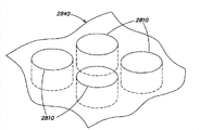
An embodiment disclosed herein relates to the large-scale sensor array (for example two-dimensional array) of a kind of chemical sensitive field effect transistor (chemical FET), and wherein the single chemical FET sensor element of array or " pixel " are set to detect the variation that occurs near the analyte concentration in array a large amount of chemistry and/or biological process (chemical reaction, cell cultivation, nervous activity, determining nucleic acid sequence process etc.).The example of the contemplated chemical FET of each embodiment of below discussing in detail includes but not limited to ion-sensitive field effect transistor (ISFET) and enzyme sensitive field effect transistor (ENFET).In an illustrative embodiments, at chemical FET sensor array, list and manufacture one or more microfluidic structures, think that the chemical reaction that may generate interested analyte provides container and/or sealing.For example, in one embodiment, microfluidic structures can be configured to be arranged on one or more " vestibules " (for example little reaction chamber) on one or more sensors of array, so that be provided with one or more sensors of given vestibule on it, detects and measure the analyte concentration in given vestibule.
In certain embodiments, this chemical FET array/Microfluidic Mixing structure can be used for the interested solution/material of analysis package containing nucleic acid.For example, this structure can be used for processing nucleic acid in the mode of sequencing nucleic acid in enormous quantities.In different aspect, this sequencing can implement to detect the homogeneity of nucleotide sequence, mononucleotide polymorphism for nucleic acid fragment detects, for expression of nucleic acid spectrum, draw and (between two or more states, compare expression of nucleic acid spectrum, for example between ill and normal structure relatively or at untreated tissue with medicine, enzyme, between the tissue that ray or chemical treatment mode are treated, compare), for haplotype (being relatively present in two allelic gene and mutant genes on each of people's object), for caryotype (homologous genes that one or more genes of identification test organization (be typically from preconceptional embryo/fetus and obtain to detect inborn defect) and the caryotype body from " normally " obtain) and for genotype (the relatively homologous genes in one or more genes of the first individuality and other individualities of same substance of a material).But will be appreciated that, although some illustrative example of concept disclosed herein is applicable to nucleic acid, process category, the application of the concept that relates to chemical FET sensor array disclosed herein is not limited to these examples.
Fig. 8 generality illustrates according to present disclosure invention embodiment, comprises the nucleic acid disposal system 1000 of extensive chemical FET array.In the following discussion, for illustrative purposes, the chemical FET sensor of array is described as to the ISFET to pH sensitivity.But, will be appreciated that, present disclosure is not limited to this aspect, and the ISFET in any embodiment of discussing herein is used as illustrative example, the chemical FET of other types also can be similarly for substituting embodiment, as further discussed in detail.On the one hand, system 1000 comprises semiconductor/Microfluidic Mixing structure 300, and it comprises ISFET sensor array 100 and microfluidic flow chamber 200.On the other hand, flow cavity 200 is set to for example, promote to be arranged on the nucleic acid-templated sequencing in flow cavity by making multiple sequencing reagent 272 (matrix dATP, dCTP, dGTP, dTTP and other reagent) controllably enter flow cavity.As shown in Figure 8, sequencing reagent enters into flow cavity 200 and can realize by one or more valves 270 and the one or more pump 274 controlled by computing machine 260.
In the system 1000 of Fig. 8, according to an embodiment, ISFET sensor array 100 monitoring occurs in the variation of the pH of the different parts of flow cavity 200, this variation be by one or more form sequencing reagent 272 matrix and nucleic acid-templated between chemical reaction cause.In other embodiments that below discuss in detail, other analytes that FET sensor array can be arranged to especially to the relevant information relevant with interested chemical reaction can be provided have susceptibility.By array control unit 250 (being also controlled by computing machine 260), can control ISFET array to obtain the data relevant with analysis measurement, and can process gathered data by computing machine 260, to obtain the significant information relevant with nucleic acid-templated processing.For example, in one embodiment, the variable quantity of pH is conventionally for example, with the quantity of matrix (dATP, dCTP, dGTP, the one in dTTP) of adding nucleic acid-templated particular type to proportional.The variation of this pH can be represented by near the variation of the output voltage of one or more ISFET of the array 100 reaction between the matrix in given type and template.Therefore, the voltage variety of the output signal of the given pixel of array can be used for detecting the quantity of the matrix of the particular type of adding the template that is arranged on the flow cavity that is arranged in given pixel top to.
On the one hand, the flow cavity 200 of the system 1000 shown in Fig. 8 can comprise the multiple vestibules (not shown in Fig. 8) in the respective sensor that is arranged on ISFET array 100.Many technology all can be used for multiple processing material to import in the vestibule of this flow cavity.For example, first flow cavity can load by comprising check order in nucleic acid-templated " microballon " centrifugal inlet hole chamber nucleic acid-templated; As an alternative, this microballon can rely on gravity and enter in vestibule.In another example, do not use microballon, but cover vestibule with one group of primer pair, and with adapter by the nucleic acid-templated flow cavity that is provided to supply primer pair (immobilization material can be added to sensor array 100 or add to as the separate chip of a chip package part or can just in time add) before nucleic acid is processed.The additive method that comprises collosol and gel can be used for the near surface of the nucleic acid-templated ISFET of being fixed to array 100.
Once nucleic acid-templated, be loaded in the corresponding vestibule of flow cavity 200, can in vestibule, implement with that bridge joint amplification, then by synthetic or coupled reaction, implement product sex change and sequencing.Can predict other amplification methods (with the method for capture product in vestibule) in vestibule, it comprises the method for isothermal or the non-isothermal amplification technique of rolling circle amplification or other utilization such as PCR.As shown in Figure 8, the reagent that comprises matrix can import flow cavity (for example, by computer-controlled valve 270 and pump 274), and diffuses in vestibule, or reagent can add flow cavity to by the additive method such as inkjet printing.In another example, flow cavity 200 can not comprise any vestibule, and can adopt the diffusion property of reagent to limit crosstalking between each sensor of ISFET array 100.
In a word, the flow cavity 200 in the system of Fig. 8 can take any-mode to be set to provide one or more analytes near ISFET array 100; For example, nucleic acid-templated (DNA) can directly fix or be applied to the position of one or more pixels of suitable proximity sensor arrays 100, or for example, on the carrier material (one or more " microballons ") being positioned on sensor array.Reagent treatment (for example enzyme) can also directly be placed near the one or more solid phase carriers on sensor or array, for the enzyme of the device that does not use vestibule or microballon of multiple biosensor application, produces the product (variation of for example ion concentration) that sensor can detect.
For the ISFET array 100 of the system 1000 shown in Fig. 8, in an embodiment, array 100 for example, is realized as the integrated circuit that utilizes standard CMOS process (0.35 micron of technique, 0.18 micron of technique) Design and manufacture, it comprise need to for detection of/measure all the sensors and the electronic installation of one or more analytes.Refer again to Fig. 1, for connecting one or more contrast electrodes 76 of ISFET array 100, can be placed in flow cavity 200 (being for example arranged on the vestibule of flow cavity " not using "), for example, or it can be exposed to reference substance (one or more sequencing reagent 172) to set up baseline, to be used near the variation of the analyte concentration corresponding ISFET of comparator array 100.Contrast electrode 76 can be electrically connected to array 100, array control unit 250 or be directly connected to computing machine 260, is beneficial to carry out the analysis measurement of the voltage signal based on obtaining from array 100; In some embodiments, contrast electrode can be linked to electrical ground or other predetermined potentials, or can measure with respect to earthy contrast electrode voltage, thereby sets up electrical reference for the measurement of ISFET output signal, as discussed further below.
As one dimension or two-dimensional array, ISFET array 100 is not limited to any specific dimensions, include as few as 2-256 pixel (for example 16 × 16 pixels in two-dimentional embodiment) or as many as 54,000,000 pixels (for example 7400 × 7400 pixels in two-dimentional embodiment) or larger, and can be used for the various chemical/biological testing goals according to concept disclosed herein.In an embodiment of the canonical system shown in Fig. 8, the single ISFET sensor of array can be set to hydrogen ion sensitivity; But, it is also recognized that present disclosure is not limited to this respect, for example single-sensor of ISFET sensor array can be set to especially to for example, having susceptibility for the other types ion concentration of various application (material to known other ion-sensitives such as sodium, silver, iron, bromine, iodine, calcium and nitrate).
In general, according to the chemical FET array of each embodiment of present disclosure can be set to in various analyte/chemical substances any one or multiplely there is susceptibility.In one embodiment, one or more analytes that the one or more chemical FET of array for example can be set to, especially to representing one or more binding events (relevant with determining nucleic acid sequence) have susceptibility, and in other embodiments, the different chemical FET of given array can be set to that different analytes are had to susceptibility.For example, in one embodiment, one or more sensors (pixel) of array can comprise the chemical FET of the first kind, it is set to the first analyte chemical sensitivity, and one or more other sensors of array comprise the chemical FET of Second Type, it is set to the second analyte chemical sensitivity to being different from the first analyte.In an exemplary embodiment, the first analyte can represent to process the first relevant binding events with determining nucleic acid sequence, and the second analyte can represent second binding events relevant with determining nucleic acid sequence.Certainly, will be appreciated that, can in any given array, use more than two kinds of dissimilar chemical FET, to detect and/or to measure dissimilar analyte/binding events.Conventionally, will be appreciated that in any embodiment of the sensor array of discussing herein, given sensor array can be " homogeneity " and comprise for example, the chemical FET of substantially similar or same type in order to detect and/or to measure the analyte (pH or other ion concentrations) of same type, or sensor array can be " heterogeneous " and comprise the dissimilar chemical FET in order to detect and/or to measure dissimilar analyte.In order to simplify discussed content, in each embodiment of sensor array below, again with ISFET as an example, but present disclosure is not limited to this respect, and select further (for example, in conjunction with Figure 11 A) to be below discussed for several other of analyte-sensitive.
In the exemplary embodiment based on 0.35 micrometre CMOS process technology (or thering is the more CMOS technology of small-feature-size), each pixel of ISFET array 100 can comprise ISFET and attached enabling/alternative pack, and approximately ten microns of can occupy in array surface are taken advantage of ten microns (100 microns
2) or less area; In other words, can obtain the array with approximately 10 microns or less spacing (interval of pixel to pixel).With respect to making Pixel Dimensions be at least the existing trial of 12 microns or larger manufacture ISFET, the array pitch of approximately 10 microns that utilizes 0.35 micrometre CMOS process technology has been obtained significant progress in size aspect dwindling.
More particularly, according to the inventive concept of present disclosure in some embodiment of below further discussing, the array pitch of approximately nine (9) microns makes ISFET array can comprise more than 256000 pixels (512 taking advantage of 512 array), this array is selected with corresponding row and column and the electron device of setovering/read can be manufactured on 7 millimeters and takes advantage of on the semiconductor wafer of 7 millimeters, and can being manufactured on 21 millimeters, takes advantage of on the semiconductor wafer of 21 millimeters the similar sensor array that comprises 4,000,000 pixels (2048 take advantage of 2048 array, be greater than 4,000,000 pixels).In other examples, the array pitch of approximately 5 microns makes ISFET array can comprise 1.55 million pixels (1348 taking advantage of 1152 array), this array and corresponding electronic unit can be manufactured on 9 millimeters and take advantage of on the wafer of 9 millimeters, and comprise that being greater than the ISFET sensor array of 14,000,000 pixels and corresponding electronic unit can be manufactured on 22 millimeters and take advantage of on the wafer of 20 millimeters.In other embodiments, utilize and be less than the CMOS manufacturing process (for example CMOS technology of 0.18 micron) of characteristic dimension of 0.35 micron and can manufacture the ISFET sensor array that has significantly lower than the spacing of 5 microns (for example array pitch of 2.6 microns or be less than 8 or 9 microns
2elemental area), it is for the ISFET array of very dense.Certainly, will be appreciated that, the Pixel Dimensions (for example approximately 20,50,100 microns or larger) that is greater than 10 microns also can be according to realizing in each embodiment of the chemical FET array of present disclosure.
In aspect other of the system shown in Fig. 8, one or more array control units 250 can be used for handling ISFET array 100 (for example selecting/enable the respective pixel of array to obtain the output signal that represents analysis measurement).In each embodiment, the one or more parts that form one or more array control units can be realized on same integrated circuit (IC) chip identical with array but in the different piece of IC chip together with the pixel element of these arrays, or realize outward at chip.With regard to antenna array control, the analog-to-digital conversion of the output signal of ISFET can be by the integrated circuit (IC) chip identical with ISFET array but be positioned at the circuit of realizing outside sensor array area and implement (a/D converter circuit is arranged on and has obtained less spacing outside sensor array area and therefore not only realized the sensor of larger quantity but also reduced noise).In each illustrative embodiments of below further discussing, analog-to-digital conversion can be 4,8,12,16 or according to other bit resolution of required dynamic range of signals.
The General Introduction of processing chemical FET (for example ISFET) array 100 of the example system 1000 of relevant one or more analytes with nucleic acid for measuring is provided, to the exemplary chemical FET array according to present disclosure be described in detail below, this chemistry FET array can be used in various application, and it includes but not limited to nucleic acid processing.In addition, for illustrative purposes, below utilize the particular instance of ISFET array that the chemical FET array according to present disclosure is discussed, but the chemical FET of other types also can be used in other embodiments.
As mentioned above, each invention embodiment disclosed herein is all especially for the people's such as the above-mentioned Milgrew relevant with Fig. 1-7 ISFET Array Design and the improvement that other existing ISFET Array Designs are done, to obviously reduce Pixel Dimensions and array pitch, and for given semiconductor wafer sizes, increase thus the pixel quantity (being picture element density) of ISFET array.In some embodiments, when picture element density increases, be attended by corresponding to the increase of signal to noise ratio (S/N ratio) (SNR) and the speed of this output signal that can read from array of output signal of corresponding measurement of one or more chemical property that relate to one or more analytes and increase.Particularly, applicant's empirical tests recognizing by loosening the requirement to the ISFET linearity, and emphasis is concentrated on the scope (for example, corresponding to the signal output from approximately 7 to 9 rather than 1 to 14 pH scope) of further restricting signal output/measure, can significantly reduce complexity and the size of single pixel, contribute to thus to realize very extensive intensive ISFET array.
For this reason, Fig. 9 shows the row 102 according to the ISFET array 100 of present disclosure invention embodiment
j, wherein obviously simplified ISFET Pixel Design and be beneficial to realize little Pixel Dimensions.Row 102
jcomprise n pixel, wherein first be shown in Figure 9 for pixel 105 with last pixel
1with 105
n.As below further discussed in conjunction with Figure 13, the complete two-dimentional ISFET array 100 of the row design based on shown in Fig. 9 comprises m this row 102
j(j=1,2,3 ... .m), it is generally the contiguous pixels row that are arranged side by side.
In aspect of the embodiment shown in Fig. 9, row 102
jpixel 105
1to 105
nin each only comprise three parts, i.e. ISFET150 (being also labeled as Q1) and two switch mosfet Q2 and Q3.Switch mosfet Q2 and Q3 are in response to n row selection signal (RowSel
1to RowSel
n, logic low activate) in one, to enable or to select row 102
ja given pixel.By pixel 105
1as the example of all pixels that is applied to row, via line 118
1receive after corresponding row selection signal, transistor switch Q3 is by line 112
1by controllable current source 106
jbe connected to the source electrode of ISFET150.Receiving after corresponding row selection signal, transistor switch Q2 is by line 114
1the source electrode of ISFET 150 is connected to row biasing/sensing circuit 110
j.The drain electrode of ISFET 150 is by line 116
1be directly connected to biasing/sensing circuit 110
j.Therefore, each pixel only needs four signal line, i.e. line 112
1, 114
1, 116
1with 118
1operate pixel 105
1three parts.In the array of m row, given row selection signal is for example applied to, in the pixel same position of respective column () of each row simultaneously.
As shown in Figure 9, according to the row 102 of an embodiment
jdesign be based on designing relevant cardinal rule with the people's such as the Milgrew shown in Fig. 3 row.Particularly, when the ISFET of each pixel enables, its setting has constant leakage current I
djwith constant drain-source voltage V
dSj, to obtain and come from the output signal V that enables pixel according to above-mentioned equation (3)
sj.For this reason, row 102
jcomprise a controllable current source 106
j, it is connected to the positive voltage VDDA of mimic channel and in response to voltage bias VB 1, and this voltage bias VB 1 is by all pixel sharings in row, thereby provides constant leakage current I for enabling the ISFET of pixel
dj.On the one hand, current source 106
jexecution is embodied as current mirror, and it comprises the MOSFET of two long channel lengths and high output impedance.Row also comprise biasing/sensing circuit 110
j, it is also by all pixel sharings in row, to provide constant drain-source voltage to the ISFET that enables pixel.Biasing/sensing circuit 110
jbased on Kelvin bridge, construct, and comprise two operational amplifier 107A (A1) and 107B (A2), above-mentioned two operational amplifiers are set to buffer amplifier and are connected to mimic channel positive voltage VDDA and analog power ground voltage VSSA.Biasing/sensing circuit also comprises controllable current place 108
j(being similar to current source 106j) and the MOSFET Q6 that is connected diode, controllable current place 108
jbe connected to analogue ground voltage VSSA and in response to bias voltage VB2.Bias voltage VB1 and VB2 set/controlled and complementary source and inverse current provided to work in coordination with.Due to current sink 108
jthe voltage of MOSFETQ6 that draws the mid-span diode that electric current produces at drain electrode and the source electrode two ends of ISFET of enabling pixel, is become constant drain-source voltage V by operational amplifier generation of forced
dSj.
By the biasing/sensing circuit 110 at Fig. 9
jmiddle use connects the MOSFETQ6 of diode, rather than the resistance R shown in the people's such as the Milgrew shown in Fig. 3 design
sDjthereby, obvious advantage is provided in CMOS manufacturing process.Particularly, build-out resistor generally can be fabricated to the serious forgiveness with approximately ± 20%, but the serious forgiveness of the MOSFET mating with CMOS manufacturing process is approximately ± 1% or better.Be responsible for the ISFET drain-source voltage V that provides constant
dSjparts matching degree can from row to row appreciable impact for example, from being listed as to the measuring accuracy (deviation) being listed as.Therefore, use MOSFET Q6 and do not use resistance obviously to reduce the measured deviation being listed as from being listed as to.And, although the thermal migration characteristic of resistance and ISFET can be slightly different, even if the thermal migration characteristic of MOSFET and ISFET is not to equate in fact it is substantially similar yet; Therefore, any thermal migration in MOSFET Q6 has been eliminated in fact any thermal migration of ISFET Q1, and this just causes better Measurement sensibility when array temperature changes.
In Fig. 9, line skew/sensing circuit 110j also comprises sampling/maintenance and buffer circuit, for the output signal V from row is provided
cOLj.Particularly, at the transistor Q2 by each pixel and Q3, enable or select pixel 105
1to 105
nin one after, the output of amplifier 107A (A1), buffering V
sjby for example, arriving row sampling in response to switch (transmission gate circuit) operation store of row sampling and holding signal COL SH and keeping capacitor C
shin.For sampling and keeping the example of the appropriate electrical capacitance of electric capacity to include but not limited to the scope from about 500fF to 2pF.Sampling voltage is cushioned and is provided as row output signal V by row output buffer amplifier 111j (BUF)
cOLj.Also as shown in Figure 9, reference voltage V REF can be by being applied to buffer amplifier 111j in response to the switch of control signal CAL, the row that are beneficial to cause due to buffer amplifier 111j are to the heteropical characterization being listed as, and after therefore allowing, sense data is proofreaied and correct.
Fig. 9 A shows for the exemplary circuit diagram of one of them of the amplifier 107A of setover/sensing circuit 110j (identical with the circuit diagram of amplifier 107B), and Fig. 9 B is that the amplifier bias of amplifier 107A and 107B is to the curve map of bandwidth.As shown in Fig. 9 A, amplifier 107A has been used the setting of the multiple current mirror image based on nine MOSFET (M1 to M9), and is set to unified gain buffer, and wherein the input and output of amplifier are summarized respectively and are labeled as IN+ and VOUT.The transimpedance of voltage bias VB 4 (representing corresponding bias current) control amplifier as bandwidth control (increasing bandwidth along with the increase of electric current).Referring again to Fig. 9, due to sampling and maintenance capacitor C
shexistence, when sample and holding switch is closed, the output of amplifier 107A drives in fact wave filter.Therefore,, in order to realize considerable ground high data speeds, can regulate voltage bias VB 4 higher bias current to be provided and to increase amplifier band width.From Fig. 9 B, can observe, in some illustrative embodiments, can realize at least even larger amplifier band width of 40MHz.In some embodiments, up to the amplifier band width of 100MHz, can be suitable for easily obtaining high acquisition speed and relative low pixel sampling or " time-out " time (for example approximately 10 to 20 microseconds).
The embodiment shown in Fig. 9 on the other hand in, different from the people's such as the Milgrew shown in Fig. 3 Pixel Design, pixel 105
1to 105
ndo not comprise any transmission gate circuit or other devices that simultaneously needs n raceway groove and p channel fet parts; Particularly, the pixel 105 in the present embodiment
1to 105
nonly comprise the FET device of same type (only for n raceway groove or only for p raceway groove).For illustrative purposes, the pixel 105 shown in Fig. 9
1to 105
nall be expressed as and only comprise p raceway groove parts, be i.e. two p channel mosfet Q2 and Q3 and p raceway groove ISFET 150.Not by using transmission gate circuit that the source electrode of ISFET is connected to biasing/sensing circuit 110
j, this may sacrifice ISFET output signal (is ISFET source voltage V
s) some dynamic range.But, applicant verifies and recognizes, by above-mentioned potential some output signal dynamic range (having limited potentially thus the measurement range of for example pH of given chemical characteristic), can eliminate the demand of the FET device to dissimilar (n raceway groove and p raceway groove) in each pixel, and reduce the quantity of pixel component.As 10-12 is further in below discussion by reference to the accompanying drawings, this obviously contributes to the reduction of Pixel Dimensions.Therefore, in one aspect in, this is useful balance between a kind of dynamic range reducing and less Pixel Dimensions.
The embodiment shown in Fig. 9 on the other hand in, different from the people's such as Milgrew Pixel Design, each pixel 105
1to 105
n iSFET 150 all its body is not connected to its source electrode (that is, the body that does not connect ISFET connects and the electric conductor of source electrode, and this electric conductor forces the body connection of ISFET and source electrode during operation in identical current potential).On the contrary, the connection of the body of all ISFET of array is all connected to each other and is connected to body-bias V
bODY.Although clearly do not illustrate in Fig. 9, be connected and be not equally connected to their source electrodes separately yet for the body of MOSFET Q2 and Q3, but be connected to body-bias V
bODY.Based on having in an illustrative embodiments of pixel of all p raceway groove parts, body-bias V
bODYbe connected to the ceiling voltage current potential (for example VDDA) that array can have, as by reference to the accompanying drawings 17 below further discuss.
By the body of each ISFET being connected to the source electrode that is all free of attachment to them, the source of some non-zero is to bulk voltage V
sBlikely can produce " bulk effect ", as by reference to the accompanying drawings, 1 as discussed above, it affects the threshold voltage V of ISFET according to nonlinear relationship
tH(therefore,, according to equation (3), can affect the measurement such as the chemical property of pH).But, applicant's empirical tests recognizing, by emphasis being concentrated in the dynamic range that reduces ISFET output signal, any bulk effect that may occur in ISFET because of source to the bulk voltage of non-zero all can relatively be minimized.Therefore, may cause the nonlinearity of any measurement of the dynamic range reducing can be because being inessentially left in the basket or paying attention to and compensate (for example, by array calibration and data processing technique, as in conjunction with Figure 17 below further discuss).Applicant also verifies and recognizes, by the body of each ISFET being connected to the source electrode that is all free of attachment to them, form all FET of pixel and can share a public body and connect, further promote thus the reduction of Pixel Dimensions, as in conjunction with Figure 10-12 below further discuss.Therefore, in another aspect, this is useful balance between a kind of dynamic range reducing and less Pixel Dimensions.
Figure 10 shows according to the pixel 105 shown in Fig. 9 of present disclosure invention embodiment
1the vertical view of chip layout-design.Figure 11 A shows along the compound section figure of the I-I line of the pixel shown in Figure 10, be included in other elements of Figure 10 right-hand part between II-II line and III-III line, it illustrates the stepped construction figure that pixel is manufactured, and Figure 12 A to 12L provides the vertical view (each picture sequences in Figure 12 A to 12L is stacked to form the layout-design of the pixel chip shown in Figure 10) of each manufacture layer shown in Figure 11 A.In an illustrative embodiments, the 4-metal of the Pixel Design usable criterion shown in Figure 10-12,0.35 micrometre CMOS process of 2-polysilicon are realized, so that foursquare pixel to be provided how much, it has the size " e " that is shown in Figure 10 for approximately 9 microns, and corresponding to the size " f " that is about 7 microns of the sensitizing range of ISFET.
In the vertical view of Figure 10, ISFET 150 (being labeled as Q1 in Figure 10) has occupied the illustrated right middle of pixel conventionally, and the relevant position of the grid of ISFET, source electrode and drain region is expressed as Q1
g, Q1
sand Q1
d.MOSFET Q2 and Q3 have occupied the illustrated left portion of pixel conventionally; Grid and the source electrode of MOSFET Q2 are expressed as Q2
gand Q2
s, grid and the source electrode of MOSFET Q3 are expressed as Q3
gand Q3
s.In aspect of the Butut shown in Figure 10, MOSFET Q2 and Q3 common drain, it is expressed as Q2/3
d.In another aspect, conventionally from the vertical view of Figure 10, can observe ISFET and be formed as its raceway groove and be positioned at the direction (being for example parallel to line I-I) along the first axle of pixel, and MOSFET Q2 and Q3 are formed as their raceway groove, be positioned at along the direction of the second axle perpendicular to the first axle.Figure 10 also shows four for operating the line of pixel,, is connected to the line 112 of the source electrode of Q3 that is
1, be connected to the line 114 of the source electrode of Q2
1, be connected to the line 116 of the drain electrode of ISFET
1select line 118 with the row of the grid that is connected to Q2 and Q3
1.With reference to figure 9, can recognize all bridging lines 112,114 and 116 (for example vertical line that strides across pixel in Figure 10) of all pixels in given row, and all bridging lines 118 (for example in Figure 10, level strides across the line of pixel) of all pixels in given row; Therefore,, according to the Butut shown in the Pixel Design of Fig. 9 and Figure 10, only need four metal wires across each pixel.
With reference now to the sectional view of Figure 11 A,, highly doped p-type region 156 and 158 (arranging along Figure 10 center line I-I) in n-trap 154 has formed source electrode (S) and the drain electrode (D) of ISFET, the region 160 of n-trap is set between them, and in this region, the p raceway groove of ISFET is formed on below the polysilicon gate 164 and gate oxide 165 of ISFET.According to an aspect of the invention embodiment shown in Figure 10 and 11, pixel 105
1all FET parts be all fabricated to p channel fet, it is formed in the single N-shaped trap 154 in p-type Semiconductor substrate 152.The different structure of design that can realize the people such as this and Milgrew be because, 1) in pixel, do not need transmission gate circuit; And 2) source electrode of ISFET is not connected to the body connection of n-trap.More particularly, highly doped N-shaped region 162 provides body connection (B) for n-trap 154, and as shown in Figure 10, body connects B and is connected to around pixel 105
1the metallic conductor 322 of periphery.But, body connect be not both directly electrically connected to ISFET source region 156 (, there is no connector connection and source electrode so that they have the electric conductor of same potential during operation), be not directly electrically connected to grid, source electrode or the drain electrode of any parts in pixel yet.Therefore, other p channel fet parts of pixel, i.e. Q2 and Q3, can be manufactured in same n-trap 154.
In the figure of the compound section of Figure 11 A, also can be observed the highly doped p-type region 159 (the line I-I in Figure 10 arranges) corresponding to the common drain (D) of MOSFET Q2 and Q3.For illustrative purposes, also can be observed the polysilicon gate 166 of MOSFET Q3 in Figure 11 A, although this grid arranges less than the line I-I in Figure 10, it is arranged on " after plane " along the cross section of line I-I.But, in order to simplify, each source electrode of MOSFET Q2 shown in Figure 10 and Q3, and the grid of Q2 is not all shown in Figure 11 A, due to common drain thereby all along identical axle (because they, perpendicular to illustrated plane) arrange (if shown in Figure 11 A they, these elements become very complicated by the compound section figure that makes Figure 11 A).
Except substrate, gate oxide and the polysilicon layer shown in Figure 11 A, provide multiple extra plays to come to set up electrical connection for different pixel components, it comprises therefrom through the metal level replacing and the oxide layer that form conductive through hole.According to 4-metal cmos process, these layers in Figure 11 A are labeled as " contact ", " metal 1 ", " through hole 1 ", " metal 2 ", " through hole 2 ", " metal 3 ", " through hole 3 " and " metal 4 ".In order to contribute to especially the understanding of the electrical connection to ISFET, the compound section of Figure 11 A illustrates other elements that pixel is manufactured, the right side of the vertical view of these other element between Figure 10 line II-II and III-III.For the electrical connection of ISFET, uppermost metal level 304, corresponding to the sensitizing range 178 of ISFET, is provided with the passivation layer 172 of analyte-sensitive on this sensitizing range.The polysilicon gate 164 of uppermost metal level 304 and ISFET and middle conductor 306,308,312,316,320,326 and 338 have together formed " floating boom " structure 170 of ISFET, its pattern with in the conventional ISFET design class shown in combination Fig. 1 discussed above seemingly.By being connected to line 116
1conductor 340,328,318,314 and 310 be ISFET drain electrode provides electrical connection.By conductor 334 and 336 and conductor 324 source electrode of ISFET is connected to the common drain (it arranges along the line I-I in Figure 10) of MOSFET Q2 and Q3.By conductor 330, with 332, the body that is connected to n-trap 154 is connected to 162 metallic conductors 322 that are electrically connected to the peripheral of the pixel on " metal 1 " layer.
As noted above, Figure 12 A to 12L provides the vertical view (the pixel chip layout-design shown in the stacked formation Figure 10 of each picture sequences in Figure 12 A to 12L) of each manufacture layer shown in Figure 11 A, in Figure 12, each layer to be printed on corresponding relation between alphabetical vertical view and the sectional view of Figure 11 A as follows: A) N-shaped trap 154; B) inject; C) diffusion; D) polysilicon gate 164 (ISFET) and 166 (MOSFET Q2 and Q3); E) contact; F) metal 1; G) through hole 1; H) metal 2; I) through hole 2; J) metal 3; K) through hole 3; L) metal 4 (top electrode of contact ISFET grid).The identical parts that each Reference numeral representing in Figure 12 A to 12L all exists in the compound section figure corresponding to Figure 11 A.
Therefore, Figure 10,11 and 12A to 12L shown in the layout-design of pixel chip show, according to an embodiment, the FET device of same type can be used for all parts of pixel, and all parts can be realized in single trap.This has significantly reduced the required area of pixel, contributes to thus to increase the picture element density in given area.
In an illustrative embodiments, the canopy utmost point oxide 165 of ISFET can be fabricated to the thickness with approximately 75 dusts, causes the gate-oxide capacitances C of per unit area
oxfor 4.5fF/ μ m
2.And, polysilicon gate 164 can be fabricated to the size of the channel length L (being that the scope of W/L is from approximately 2 to 3.5) with the channel width W of corresponding 1.2 μ m and from 0.35 to 0.6 μ m, and the doping in region 160 can be chosen as, and to make the carrier mobility of p raceway groove be 190cm
2/ Vs (is 1.9E10 μ m
2/ Vs).From equation (2) above, this transconductance parameters β that causes ISFET is approximately 170 to 300 μ A/V
2.In aspect other of this illustrative embodiments, analog power voltage VDDA is 3.3 volts, and biasing VB1 and VB2 are to provide the constant ISFET leakage current I of approximately 5 μ A
dj(in some embodiments, can adjust VB1 and VB2 to provide from the leakage current of approximately 1 μ A to 20 μ A).For example, and the size of MOSFET Q6 (referring to the biasing/sensing circuit 110j in Fig. 9) is set to its channel width-over-length ratio (W/L is approximately 50) and makes the given electric current I at 5 μ A
djunder, the voltage at Q6 two ends is that 800mV (is V
dSj=800mV).From equation (3), based on these exemplary parameter, this provides the pixel output voltage V in approximately 0.5 to 2.5 volt range
sjand the ISFET threshold voltage variation in approximately 0 to 2 volt range.
For the analyte-sensitive passivation layer 172 shown in Figure 11 A, in exemplary CMOS implementation procedure, passivation layer can be especially to pH sensitivity, and can comprise silicon nitride (Si
3n
4) and/or silicon oxynitride (Si
2n
2o).In stand CMOS, passivation layer can form by these materials of one or many successive sedimentation, and be commonly used to process or covering device with protection device avoid pollute and increase electrical stability.The material character that silicon nitride and silicon oxynitride have makes the passivation layer that comprises these materials provide score protection conduct can play to the diffusion of water and sodium the restraining barrier effectively stopping, and the diffusion of water and sodium can cause the metallization structure of device to be corroded and/or the operation of device becomes unstable.The passivation layer that comprises silicon nitride and/or silicon oxynitride also provides ion-sensitive in ISFET device, this is because the surface group that passivation layer comprises can give or accept the proton from the analyte solution being in contact with it, and has changed thus the threshold voltage V of surface potential and device
tH, as in conjunction with Fig. 1 as discussed above.
For the CMOS technique of utilizing aluminium (its fusing point is about 650 degrees Celsius) as metal, generally by plasma enhanced chemical vapor deposition (PECVD), form the passivation layer of silicon nitride and/or silicon oxynitride, wherein the glow discharge of 250-350 degree Celsius, the component gas that forms silicon nitride or silicon oxynitride is ionized, produce the spike in wafer surface reaction, thereby formed the lamination of respective material.In an illustrative processes, embryo deposit that can be by silicon oxynitride thin layer (approximately 0.2 to 0.4 μ m), carry out subsequently silicon oxynitride compared with the deposition of thick-layer (approximately 0.5 μ m) and the last deposition of silicon nitride (approximately 0.5 μ m) forms the passivation layer with approximately 1.0 to 1.5 μ m thickness.Because adopt low deposition temperature in pecvd process, so aluminum metallization can not affect adversely.
But, applicant's empirical tests recognizing, although low temperature pecvd process provides sufficient passivation for conventional cmos device, low temperature process produces low-density and the passivation layer of porous slightly conventionally, and it can adversely affect the stability of the threshold voltage of ISFET in some cases.Particularly at the duration of work of ISFET device, as time goes by, low density porous passivation layer can be from solution adion saturated by these ions institutes, this so can cause not wishing the ISFET threshold voltage V occurring
tHtime become skew, thereby precision measurement is faced the challenge.
In view of the foregoing, in one embodiment, replace the CMOS technique of aluminium to can be used to manufacture according to the ISFET array of present disclosure with tungsten.The high-melting-point (more than 3400 degrees Celsius) of tungsten allows to use low-pressure chemical vapor deposition (LPCVD) technique (for example approximately 700 to 800 degrees Celsius) with higher temperature to manufacture silicon nitride or passivation layer of silicon oxynitride.Conventionally, LPCVD technique can produce for the greater density of passivation layer and the film of less hole, alleviates thus the potential for adverse effects that causes the threshold voltage shift of ISFET from analyte solution adion.
In the aluminium base CMOS technique of use, manufacture according in another embodiment of the ISFET array of present disclosure, the passivation layer 172 shown in Figure 11 A can comprise other deposition processs and/or the material except typical deposition process and/or material for stand CMOS.For example, passivation layer 172 can comprise the initial low temperature plasma assistant depositing (PECVD) of silicon nitride as above and/or silicon oxynitride; Concerning this content of the discussions, these conventional sediments that illustrate in Figure 11 A are as the Part I 172A of passivation layer 172.In one embodiment, Part I 172A deposits one or more other passivating materials to form at least Part II 172B, to increase the density of whole passivation layer 172 and to reduce factor of porosity (and adsorbability) after forming.But shown extention 172B is mainly used in the explanation to Figure 11 A, will be appreciated that present disclosure is not limited to this respect, because whole passivation layer 172 can comprise two or more ingredients, wherein various piece all can comprise the one or more layers that consist of identical or different material, and corresponding part can have similar or different structures.
The example to the responsive especially material of hydrogen ion that is applicable to the Part II 172B (or other parts) of passivation layer 172 includes but not limited to silicon nitride, silicon oxynitride, aluminium oxide (Al
2o
3), tantalum oxide (Ta
3o
5), tin oxide (SnO
2) and silicon dioxide ((SiO
2).On the one hand, can deposit Part II 172B (or other parts) by the technique of various relative low temperatures, it includes but not limited to RF sputter, DC magnetron sputtering, heat or electron beam evaporation and ion assisted deposition.On the other hand, can before the deposition of Part II 172B, use pre-sputtering etch process, to remove any native oxide (as an alternative, can be used for removing the native oxide on Part I 172A such as the reductibility atmosphere of high temperature hydrogen atmosphere) on Part I 172A.Another aspect, as mentioned above, the thickness of Part II 172B can be approximately 0.04 μ m to 0.06 μ m (400 to 600 dust), and the thickness of Part I can be approximately 1.0 to 1.5 μ m.In some embodiments, Part I 172A can comprise the multilayer of silicon oxynitride and silicon nitride, and the combination thickness of this multilayer is 1.0 to 1.5 μ m, and Part II 172B can comprise the individual layer of aluminium oxide or tantalum oxide, and this thickness in monolayer is about 400 to 600 dusts.In addition, will be appreciated that the object that provides above-mentioned exemplary thickness to be mainly used in explanation, and present disclosure is not limited to these aspects.
Therefore, be understandable that, the chemical FET array of explanation can be used for detecting multiple analytes herein, and can monitor various reactions and/or interaction by this detection.Will also be appreciated that and focus on that hydrionic detection (form with the variation of pH is carried out) is that other analytes (comprising other ions) can replace the hydrogen in these explanations for easy and for purpose of brevity.
The chemical FET of the ISFET of comprising disclosed herein can detect any analyte itself can Induced Electric Field changing.Analyte is without charged in order to be detected by sensor.For example, according to an embodiment, analyte can positively charged (being kation), electronegative (being negative ion), for zwitter-ion (can have that two electric weight equate and electrical contrary electric charge, but entirety being electric neutrality) and for polarization but still be neutral.This list incomplete, those skilled in the art can expect the material in other amalyzing substances classes and each kind in light of the disclosure herein.
In meaning the most widely of the present invention, passivation layer can cover or not cover, and analyte can in conjunction with or can be not in conjunction with passivation layer.As an example, passivation layer can consist of silicon nitride, and analyte can be other materials except hydrogen ion.As a particular instance, passivation layer can consist of silicon nitride, and analyte can be inorganic pyrophosphate (PPi).In these examples, direct-detection PPi (that is, not directly or indirectly being attached to the PPi acceptor of passivation layer).
If the analyte detecting is hydrogen (or replaceable for oxyhydroxide), preferably use weak buffering agent, to any variation of ionic species can be detected at passivation layer place.If the analyte detecting is dehydrogenation (or oxyhydroxide) other materials in addition, but some possibility that exists pH to change during reaction or detecting step, preferably use strong buffering agent, so that the variation of pH can not disturbed the detection to analyte.Buffering agent is the ionic molecule that a kind of pH of opposing changes.Buffering agent can neutralize and adds to or result from acid or the alkali in solution, and this causes in solution does not have significant pH to change.As long as be understandable that the pKa having in required scope, buffering agent is all suitable arbitrarily.Suitable buffering agent is the buffering agent that can bring into play function within the scope of approximately 6 to 9 pH, and more preferably in 6.5 to 8.5 scope.The intensity of buffering agent is relative, because it depends on, adds to or results from acid in interested solution or character, intensity and the concentration of alkali.Weak buffering agent is a kind ofly to allow to detect (therefore can not control) and be at least about the buffering agent that +/-0.005,0.01,0.015,0.02,0.03,0.04,0.05,0.10,0.15,0.20,0.25,0.30,0.35,0.45,0.50 or larger pH change.In certain embodiments, the variation of pH was approximately for 0.005 (for example each nucleotide merges), and was preferably pH increase.Strong buffering agent is that a kind of control is at least about the buffering agent that +/-0.005,0.01,0.015,0.02,0.03,0.04,0.05,0.10,0.15,0.20,0.25,0.30,0.35,0.45,0.50 or larger pH change.Can change buffering agent intensity by the concentration that changes buffer substance itself.Therefore low concentration buffer can be low-intensity buffering agent.Example comprises that those have the buffering agent that is less than 1mM (for example 50-100 μ M) buffer substance.A unrestricted example of the weak buffering agent of the sequencing reaction of reading pH variation that is applicable to illustrate is herein 0.1mM Tris or Tricine.The example of the weak buffering agent applicatory providing in example is also known in this area.The intensity of the higher buffering agent of buffer concentration may be stronger.The example comprises those with 1-25mM buffer substance.A unrestricted example of the strong buffering agent of sequencing that the PPi that is applicable to illustrate herein directly reads reaction is 1.5 or 25mM (or larger) Tris or Tricine.Those skilled in the art can be identified for reaction that the present invention contains and the optimum buffering agent of detection method.
In certain embodiments, passivation layer and/or covering molecule thereon indicate the analyte specificity of array readout device.
The detection of hydrogen ion (with the form of pH) can utilize by silicon nitride (Si
3n
4), silicon oxynitride (Si
2n
2o), monox (SiO
2), aluminium oxide (Al
2o
3), tantalum pentoxide (Ta
2o
5), tin oxide or tin ash (SnO
2) etc. the passivation layer made implement.
Passivation layer can also direct-detection other ionic species include but not limited to calcium, potassium, sodium, iodine, magnesium, chlorine, lithium, lead, silver, cadmium, nitrate radical, phosphate radical, dihydrogen phosphoric acid root etc.
In certain embodiments, passivation layer is coated with the acceptor for interested analyte.Receptor-selective combining target analyte.As used herein, the acceptor of selective binding analyte is preferentially in conjunction with this analyte molecule of (that is, its binding affinity to this analyte is greater than its binding affinity to any other analyte).Its binding affinity for target analytes can be 2 times, 3 times, 4 times, 5 times, 6 times, 7 times, 8 times, 9 times, 10 times, 15 times, 20 times, 25 times, 30 times, 40 times, 50 times, 100 times or larger of binding affinity to any other analyte.Except its RA, acceptor also must have absolute binding affinity, and this absolute binding affinity is the binding affinity (that is, it must have enough sensitivity) that is enough to effective combining target analyte.It is suitable having at picomole to the acceptor of the binding affinity in micro-molar range.Preferably, this interaction is reversible.
Acceptor can be any natural material (for example, chemicals, nucleic acid, peptide, lipid, its combination etc.).Analyte can be also any natural material, as long as the acceptor of the selectivity of existence and its combination and in some cases special specificity and its combination.But be understandable that, the present invention has also considered the detection of analyte in the situation that not there is not acceptor.Such a example is not have the detection to PPi and Pi by passivation layer in the situation of PPi or Pi acceptor.
On the one hand, the acceptor that the present invention pays close attention to is ionophore.As used herein, ionophore is no matter a kind of selective binding ionic species is the molecule of kation or negative ion.In category of the present invention, ionophore is acceptor, with the ion of its combination be analyte.Ionophore of the present invention comprises the charge carrier ionophore (that is, being attached to the little lipid soluble molecule of specific ion) that derives from microorganism well known in the art.Can be from the commercial various ionophores in there, source of for example Calbiochem.
Can be by utilizing passivation layer itself or covering acceptor on passivation layer and realize the detection of some ion by utilization.For example, utilize polysiloxane, valinomycins or salinomycin optionally to detect potassium; Utilize coban, nystatin or SQI-Pr optionally to detect sodium; Utilize ionomycin, calcimycin (A23187) or CA 1001 (ETH 1001) optionally to detect calcium.
In some cases, also can use can be in conjunction with the acceptor more than a kind of ion.For example, muscardine toxin can be used for detecting calcium and/or barium ion, and nigericin can be used for detecting potassium, hydrogen and/or lead ion, and gramicidin (gramicidin) can be used for detecting hydrogen, sodium and/or potassium ion.Those skilled in the art can recognize these compounds can be used for not requiring single ionic specificity wherein can (or can not) existence or the application of generation other ions of being combined with compound in.
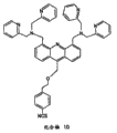
Other embodiments include but not limited to determining nucleic acid sequence application, can utilize the acceptor of selective binding inorganic pyrophosphate (PPi).The example of PPi acceptor comprises the compound shown in Figure 11 B (compound 1-10).Compound 1 is recorded in Angew Chem Int Ed 200443:4777-4780 and US2005/0119497A1, is called p-naphthyl-bis-[(two (2-pyridyl methyl) amino) methyl] phenol.Compound 2 is recorded in J Am Chem Soc 2003 125:7752-7753 and US2005/0119497 A1, is called p-(p-nitrophenylazo)-bis-[(two (2-pyridyl methyl isophthalic acid) amino) methyl] phenol (or its double-core Zn complex).Compound 3 is recorded in Sensors and Actuators B1995 29:324-327.Compound 4 is recorded in Angew Chem Int Ed 200241 (20): in 3811-3814.Compound 5 is recorded in WO 2007/002204, is wherein called two-Zn
2+-bipyridine methyl amine (Zn
2+-DPA).The synthetic schemes of compound 1 and 2 provides and illustrates in US2005/0119497 A1.The exemplary of compound 4 shown in Figure 11 C synthesized.Compound 10 shown in Figure 11 E adheres to metal oxide surface.
As another example, for the acceptor of neurotoxin, be recorded in SimonianElectroanalysis 2004,16:1896-1906.
Can covalency or the non-covalent passivation layer that is connected to of acceptor.Acceptor can be directly or indirectly (for example, to pass through coupling agent) to the covalently bound of passivation layer.Figure 11 D illustrates and utilizes silanol chemistry that acceptor is covalently bound to passivation layer.Acceptor for example can utilize aliphatic primary amine (lower left quarter) or aryl isothiocyanate (right lower quadrant) and be fixed on passivation layer.In these and other embodiments, passivation layer itself can consist of silicon nitride, aluminium oxide, monox, tantalum pentoxide etc., and is attached to silylation layer by its reaction surface group.In order to be described in more detail the chemical treatment of the silanol for being covalently bound to FET surface, at least following disclosure can be used as reference: for silicon nitride, referring to Sensors and Actuators B 1995 29:324-327, Jpn J Appl Phys 199938:3912-3917 and Langmuir 2005 21:395-402; For monox, referring to Protein Sci 1995 4:2532-2544 and Am Biotechnol Lab 200220 (7): 16-18; And for aluminium oxide, referring to Colloids and Surfaces 1992 63:1-9, Sensors andAccuators B 2003 89:40-47, and Bioconjugate Chem 1997 8:424-433.Then the reactive group to silanization layer by acceptor conjugation.This follow-up combination can directly or indirectly occur by utilizing difunctional coupling agent, as shown in Figure 11 D.Difunctional coupling agent is that a kind of have can be in conjunction with the compound of at least two reactive groups of two parts.In some cases, reactive group is positioned at the two ends of coupling agent.In certain embodiments, difunctional coupling agent is general difunctional coupling agent, those shown in Figure 11 D.General coupling agent is the coupling agent that can be used for connecting multiple part.Will be appreciated that the chemical treatment shown in Figure 11 D is intended to explanation rather than restriction.
Difunctional coupling agent can be homogeneity difunctional coupling agent or heterogeneous difunctional coupling agent, this depend on will in conjunction with the character of molecule.Homogeneity difunctional coupling agent has two identical reactive groups.Heterogeneous difunctional coupling agent has two different reactive groups.Commercially available various coupling agents can react with one or more of following groups: primary amine, secondary amine, sulfydryl, carboxyl, carbonyl and hydrocarbon.The example of amine specificity coupling agent is suberic acid two (thiosuccimide) ester, two [2-(succinimide oxygen base carbonyl oxygen base) ethyl] sulfone, disuccinimidyl suberate, tartrate two succinimide esters, diimine for dimethyl adipate dihydrochloride (dimethyl adipimate2 HCl), heptan two imidic acid dimethyl ester dihydrochloride, pungent two imidic acid dimethyl ester dihydrochlorides and two-[succinimido-[succinic acid]] glycol ester.The coupling agent that can react with sulfydryl comprises dimaleimide base hexane, Isosorbide-5-Nitrae-bis--[3 '-(2 '-pyridine radicals disulfide group)-propionamido-)] butane, 1-[p-azido salicylamide base]-4-[iodo-acetamide base] butane and N-[4-(p-azido salicylamide base) butyl]-3 '-[2 '-pyridine radicals disulfide group] propionamide.Coupling agent preferential and that hydrocarbon reacts comprises triazobenzene formylhydrazine.Preferably, the coupling agent that preferential and carboxyl reacts comprises 4-[p-azido salicylamide base] butylamine.
The heterogeneous difunctional coupling agent reacting with amine and sulfydryl comprises propionic acid N-succinimido-3-[2-pyridine radicals disulfide group] fat, [4-iodo acetyl] aminobenzoic acid succinimide ester, 4-[N-maleimide ylmethyl] cyclohexane-1-carboxylic acid succinimide ester, m-dimaleoyl imino benzoyl-N-N-Hydroxysuccinimide fat, 6-[3-[2-pyridine radicals disulfide group] propionamido-] caproic acid sulfo-maleimide ester and 4-[N-maleimide ylmethyl] cyclohexane-1-carboxylic acid sulfo-maleimide ester.The heterogeneous difunctional coupling agent reacting with carboxyl and amido comprises 1-ethyl-3-[3-dimethyl aminopropyl] carbodiimide hydrochloride.The heterogeneous difunctional coupling agent reacting with hydrocarbon and sulfydryl comprises 4-[N-maleimide ylmethyl] cyclohexane-1-carboxyl hydrazides dihydrochloride, 4-(4-N-dimaleoyl imino phenyl) butyric acid hydrazides dihydrochloride and 3-[2-pyridine radicals disulfide group] propionyl hydrazine.
As an alternative, acceptor can be noncovalently to cover on passivation layer.Acceptor non-covalent deposition on passivation layer can comprise utilizes polymer matrix.Polymkeric substance can natural existence or non-natural exist, and can include but not limited to any type of nucleic acid (such as DNA, RNA, PNA, LNA etc. or its analogies, derivant or its combination), amino acid (such as peptide, protein (natural or sex change) etc., or its analogies, derivant or its combination), lipoid, polysaccharide and functionalization segmented copolymer.Acceptor can be adsorbed on polymer matrix and/or is embedded in polymer matrix.
As an alternative, acceptor can covalency conjugation or is linked to polymkeric substance (for example, its can " grafting " to functionalized polymer).
An example of suitable peptide polymkeric substance is polylysine (for example PLL).The example of other polymkeric substance comprises segmented copolymer, and it comprises polyglycol (PEG), polyamide, polycarbonate, poly-cycloalkanes, poly alkylene glycol, polyalkylene oxide, polyalkylene terephthalates, many vinyl alcohols, polyvingl ether, polyvinyl ester, polyvinylhalide, polyvinylpyrrolidone, polyglycols, polysiloxane, polyurethane, alkylcellulose, hydroxy alkyl cellulose, cellulose ether, cellulose esters, NC Nitroncellulose, the polymkeric substance of acrylic acid and methacrylate, methylcellulose, ethyl cellulose, hydroxypropyl cellulose, HPMC, hydroxyl fourth methylcellulose, cellulose acetate ester, cellulose propionate ester, butyric acid cellulose acetate ester, cellulose acetate phthalate ester, carboxyethyl cellulose, cellulose triacetate, cellulose sulfate sodium salt, poly-(methyl methacrylate), poly-(β-dimethyl-aminoethylmethacrylate), poly-(butyl methacrylate), poly-(isobutyl methacrylate), poly-(hexyl methacrylate), poly-(isodecyl methacrylate), poly-(lauryl methacrylate), poly-(phenyl methacrylate), poly-(methyl acrylate), poly-(isopropyl acrylate), poly-(isobutyl acrylate), poly-(acrylic acid stearyl), tygon, polypropylene, PEG, poly-(oxirane), poly-(ethylene glycol terephthalate), poly-(vinyl alcohol), polyvinyl acetate, Polyvinylchloride, polystyrene, poly-hyaluronic acid, casein, gel, gelatin, polyanhydride, polyacrylic acid, alginates, shitosan, poly-(methyl methacrylate), poly-(β-dimethyl-aminoethylmethacrylate), poly-(butyl methacrylate), poly-(isobutyl methacrylate), poly-(hexyl methacrylate), poly-(isodecyl methacrylate), poly-(lauryl methacrylate), poly-(phenyl methacrylate), poly-(methyl acrylate), poly-(isopropyl acrylate), poly-(isobutyl acrylate), poly-(acrylic acid stearyl), poly-(lactide-glycolide), oxalates multipolymer, polycaprolactone, polyesteramide, poe, poly butyric, polyanhydride, poly-(styrene-block-isobutylene-block-styrene) (SIBS) segmented copolymer, ethylene vinyl acetate, poly-(methyl) acrylic acid, the polymkeric substance of lactic acid and glycollic acid, polyanhydride, poly-(ortho acid) ester, polyurethane, poly-(butyric acid), poly-(valeric acid), with poly-(lactide-caprolactone), and natural polymer is as alginates, and other polysaccharide comprise glucosan and cellulose, collagen, albumin, with other hydrophilic protein, zein and other prolamin and hydrophobic protein, multipolymer and its potpourri, and chemical derivative comprises replacement and/or the interpolation of chemical group, for example alkylation, alkylidene, hydroxylation, the conventional modification that oxidation and other those skilled in the art carry out.
Comprise that with threshold voltage stability and/or predictable another relevant problem of ISFET trap-charge can accumulate on the metal level with the manufacture of CMOS technique, this is for example, such as, because various technique activities (production line last part technology, plasma metal etch, wafer cleaning, cutting, encapsulation, conveying etc.) during array manufacture or afterwards cause.Particularly, with reference to Figure 11 A, in some cases, trap-charge can accumulation on the one or more different conductors 304,306,308,312,316,320,326,338 and 164 that form ISFET floating gate structure 170.This phenomenon is also called " antenna effect " in related documents.
A chance of accumulation trap-charge comprises the plasma etching of top metal level 304.Applicant empirical tests and recognize other chances that trap-charge accumulates on one or more conductors of floating gate structure comprise during the process of lapping of scribing machine of cut crystal can produce wafer cutting and/or each post-process wafer conveying/encapsulation step of static, wherein the automated machine of handling/transfer wafers can be the source of the conductor static discharge (ESD) to floating gate structure.If do not remove for silicon substrate (or other Semiconductor substrate) provides to connect to form the electric pathway that this electric charge gathers, electric charge can be increased to the degree (for example charge injection enters oxide or puncture lower oxyde to arrive below substrate) that causes gate oxide 165 that less desirable variation or damage occur.In gate oxide or the trap-charge at gate oxide-interface place also can cause the variation of less desirable and/or unpredictalbe ISFET operation and performance.
Consider above-mentioned reason, other invention embodiments of present disclosure relate to the method and apparatus that promotes ISFET performance by reducing trap-charge or alleviating antenna effect.In one embodiment, can after sensor array manufacture completes, reduce trap-charge, and in other embodiments, can improve manufacturing process itself and reduce the trap-charge of being inducted by some common process step.In other embodiments, " during manufacture " and " manufacturing afterwards " technology that can be used in combination reduces trap-charge, and promotes thus the performance of ISFET.
For changing manufacturing process itself, reduce trap-charge, in one embodiment, can specifically select the thickness of the gate oxide 165 shown in Figure 11 A, be beneficial to remove the stored charge of substrate; Particularly, compared with thin gate oxide, can make a large amount of electric charges that produce through gate oxide until the substrate under it and not being captured.According in another embodiment of this viewpoint, can be to comprise extra " sacrifice " device by Pixel Design, that is, have than also another transistor of thin canopy utmost point oxide of the gate oxide of ISFET 165.Then, the floating gate structure of ISFET can be connected to the grid of sacrificing device, so that it is with being " electric charge removes transistor ".Certainly, will be appreciated that some half-way house that comprises this sacrifice device comprises increase Pixel Dimensions and complexity.
In another embodiment, before plasma etching, the top metal level 304 of the ISFET floating gate structure 170 shown in available dielectric coverage diagram 11A, to reduce trap-charge.As mentioned above, in some cases, the electric charge accumulating in floating gate structure is relevant with the plasma for metal etch.Conventionally, photoresist is applied on metal to be etched, then according to the required geometric figure of below metal, is patterned.In an illustrative embodiments, before photoresist applies, cover dielectric layer (for example oxide) and can deposit on metal to be etched, so that an extra restraining barrier of the electric charge for stopping plasma etching process generation to be provided in metal surface.On the one hand, covering dielectric layer can stay in the continuation of insurance of subsequent technique relaying, and it forms a part for passivation layer 172.
In another embodiment, for the metal etching process of top metal level 304, can be improved to and comprise that wet-chemical or ion beam grind, rather than plasma etching.For example, can carry out etch metal layers 304 (for example, referring to http://www.transene.com/aluminum.html, being incorporated to by reference herein at this its full content) with below dielectric being there is to optionally aqueous chemical processing.Another alternative method is to use ion to grind rather than plasma etching to metal level 304.Ion grinds and is generally used for the material that etching can not easily utilize conventional plasma or wet-chemical treatment to remove.Ion grinding technics is not used the oscillating electric field in plasma process, therefore can in metal level, not produce electric charge.Another metal etch alternative method comprises that optimization condition of plasma is to reduce etching speed (less power density).
The structure that in another embodiment, can change metal level is beneficial to during manufacturing floating boom electrical isolation completely.On the one hand, by metal designs, be stacked, so that large area ISFET floating boom may need not connect any structure as the subsequent metal layer of " wire jumper " during realizing the final manufacture of the electrical connection to transistor floating boom at it.This " wire jumper " connects design and avoided electric charge to flow to transistor from large floating boom.This method can realize by following steps (M=metal level): i) M1 contact polygate electrodes; Ii) M2 contact M1; Iii) M3 limits floating boom and utilizes isolated island and M2 disconnects; Iv) have the M4 wire jumper of very little area, it is etched and connect floating boom M3 on isolated island, by the M1/M2/M3 lamination that M3 floating boom is connected to just in time the polysilicon gate on transistor active region is connected; And v) only remove the interlayer dielectric between M3 and the M4 on floating boom, to expose exposed M3 floating boom.In said method general introduction, can not need implementation step v), because the passivation layer of M4 is stayed on the floating boom of M4 according to the ISFET structure of some embodiment discussed above.On the one hand, remove the performance (being sensitivity) that still can promote in other respects ISFET.In a word, the final chemical-sensitive passivation layer forming can be thin sputtering sedimentation ion-sensitive metal oxide layer.Will be appreciated that wire jumper structure in top layer discussed above can realize in standard CMOS manufacturing process, thereby make any metal level in three initial metal levels as floating boom (being M1, M2 or M3).
For the rear manufacturing process that reduces trap-charge, in one embodiment, " forming gas annealing " can be used as rear manufacturing process, to reduce the potential adverse effect of trap-charge.In forming gas annealing, the ISFET device that thermal treatment is manufactured by CMOS under the atmosphere of hydrogen and nitrogen mixture.Hydrogen in potpourri diffuse into gate oxide 165 and in and particular form exist trap-charge.On the one hand, forming gas annealing need not solve all gate oxides that caused by trap-charge and damages; But in some cases, the part neutralization of some trap-charge has been enough to significantly promote to the performance of ISFET.According in the exemplary annealing in process of present disclosure, ISFET can be in the hydrogen/nitrogen mixture gas of hydrogen that comprises 10% to 15%, 400 to 425 degrees Celsius of lower thermal treatments approximately 30 to 60 minutes.In a specific embodiment, in the hydrogen/nitrogen mixture gas of hydrogen that comprises 10%, 425 degrees Celsius of lower thermal treatments approximately 30 minutes, can observe the performance of lifting ISFET effective especially.For aluminium CMOS technique, annealing temperature should remain on 450 degrees Celsius or lower than this temperature, to avoid destroying the metallurgy of aluminium.According to the annealing process of present disclosure on the other hand in, after having manufactured the wafer of ISFET array, cutting implements forming gas annealing, to guarantee effectively to improve the defect for example, causing because of the trap-charge that cutting technique itself causes and/or other precut processing steps (plasma etching of metal).
According to the embodiment of present disclosure for reducing the other technique of trap-charge potential for adverse effects, adopt various " static discharge (ESD)-responsive schemes " during can manufacturing conveying/encapsulation step after any multiple wafer.For example, in an illustrative processes, can use antistatic dicing to bring wafer substrates is fixed on to appropriate location (for example, during cutting process).And, for example, although the deionized water of high resistivity (10M Ω) is conventionally used in scribing machine cooling, but according to present disclosure embodiment, less resistive rate/larger conductive water can be used for this object, is beneficial to electric charge and conducts through water; For example, can process deionized water with carbon dioxide, to reduce resistivity and to improve the conduction for electric charge that cutting technique is produced.And, can during each wafer cutting/conveying/encapsulation step, use the wafer with good earth to eject instrument, again for the electric charge producing in any these steps provides effective conducting path, reduce thus the chance of stored charge on one or more conductors of floating gate structure of each ISFET of array.
Relating in another embodiment of the rear manufacturing process that reduces trap-charge, can irradiate with UV radiation the gate oxide area of ISFET.Refer again to Figure 11 A, in an illustrative embodiments based on the present embodiment, in the manufacture process of ISFET array, in the top metal level 304 of each pixel of array, can comprise an optional hole or window 302, it approaches the floating gate structure of ISFET.When UV radiation produces, this window is intended to UV radiation to introduce the area of grid of ISFET; Particularly, the pixel 105 as shown in Figure 11 and 12A-L
1each layer be configured such that the UV radiation that enters window 302 is able to substantially unhinderedly to clash near region polysilicon gate 164 and gate oxide 165.
In order to be beneficial to the UV radiation process that reduces trap-charge, applicant's empirical tests recognize and conventionally need to use the other materials except silicon nitride and silicon oxynitride in the passivation layer 172 shown in Figure 11 A, this is because silicon nitride and silicon oxynitride seriously absorb UV radiation.In view of the above problems, these material requires are replaced the very transparent material of UV radiation by other, and the example of these interchangeable materials includes but not limited to phosphosilicate glass (PSG) and boron Doping Phosphorus silicate glass (BPSG).But PSG and BPSG can see through hydrogen and hydroxide ion; Therefore, in order to use in the passivation layer of the ISFET design to pH sensitivity, PSG and BPSG can together be used and form passivation layer by permeable material with ion, and this ion can for example aluminium oxide (Al of permeable material
2o
3) also very transparent to UV radiation.For example, refer again to Figure 11 A, can in the 172A of the first area of passivation layer 172, with PSG or BPSG, replace silicon nitride or silicon oxynitride, and can in the Part II 172B of passivation layer 172, use aluminium oxide thin layer (for example 400 to 600 dusts) (for example, can utilize rear CMOS lift-off photolithography process to carry out deposition of aluminium oxide).
Comprise UV radiation embodiment on the other hand in, each ISFET of sensor array must be during UV irradiation treatment suitably biasing, be beneficial to the minimizing of trap-charge.Especially, clash into wherein form ISFET conduction bulk silicon region 160 derive from UV radiation high-energy photon produce electron hole pair, its contribute to when electric current flows through the conduction of ISFET in and gate oxide in trap-charge.For this reason, in conjunction with Figure 17, at the array control unit of below further discussing, during UV irradiation treatment, produce the signal of the suitable ISFET for the array of setovering.Especially, refer again to Fig. 9, produce RowSel
1to RowSel
neach signal (open) all row of sensor array to enable/select simultaneously, and thus all ISFET of array are connected to the corresponding controllable current source 106 in each row
j.Along with all pixels of each row are simultaneously selected, from the current source 106 of given row
jby all pixels in row, shared.By removing bias voltage VB4, close column amplifier 107A and 107B, meanwhile, by the switch corresponding to control signal " UV ", will be connected to the output ground connection of amplifier 107B of drain electrode of each ISFET in given row.And, for the sharing body voltage V of all ISFET of array
bODYbe connected to (is V electrical ground
bODY=0 volt) (as mentioned above, in the general operation of array, bias voltage V
bODYbe connected to the ceiling voltage current potential that can be used for array, for example VDDA).In an example process, for all controllable current sources 106
jbias voltage VB1 be configured such that the ISFET of each pixel conducts the electric current of approximately 1 μ A.At ISFET array so after biasing, utilize the UV radiation of enough radiant quantity to carry out radiating curtain and (for example, at matrix, be listed as the distance of approximately an inch, utilize to come to produce about 20milliWatts/cm
2the EPROM eraser of radiation irradiates approximately 1 hour).After treatment with irradiation, before the measurement of the chemical property for such as ion concentration, make array static and stablize more than several hours.
Figure 13 shows according to the block diagram at the exemplary CMOS IC chip embodiment of the ISFET of row discussed above and Pixel Design sensor array 100 in conjunction with Fig. 9-12.In aspect of the present embodiment, array 100 comprises 512 row 102
1to 102
512, these row all have corresponding row biasing/sensing circuit 110
1to 110
512(each corresponding row, as shown in Figure 9), wherein each row comprise 512 how much square pixel 105
1to 105
512, each pixel all has approximately 9 microns and takes advantage of the size (being that array is that 512 row are taken advantage of 512 row) of 9 microns.On the other hand, whole array (comprising pixel and corresponding line and column select circuit and row biasing/sensing circuit) can be manufactured on as having on the semi-conductor chip of approximately 7 millimeters of special ICs (ASIC) of taking advantage of 7 mm sizes.When 512 arrays of taking advantage of 512 pixels are shown in the embodiment of Figure 13 time, will be appreciated that, according to other embodiments, can realize this array with the row and column of different numbers and different Pixel Dimensions, as in conjunction with Figure 19-23 below further discuss.
And, as mentioned above, will be appreciated that according to the array of each embodiment of the present invention and all can for example, according to conventional cmos manufacturing technology and improved CMOS manufacturing technology (contribute to realize each functionalization characteristic of the chemical FET array of discussing herein, such as the additional deposition of passivating material, reduce the processing step of trap-charge etc.) and other semiconductor fabrications except the technology of using in these conventional cmos manufactures, manufacture.Therefore, can use various photoetching techniques to be used as a part for array fabrication process.For example, in an illustrative embodiments, can use a kind of photoetching technique, wherein by the edge of overlapping step and position apart from approximately 0.2 micron of wafer substrates repeatedly photolithographic exposure make together with the block " stitching " of suitably design.In single exposure, maximum chip size is exemplarily for approximately 21 millimeters are taken advantage of 21 millimeters.By the selectivity different block (side, top and bottom, core etc.) that exposes, can on wafer, limit very large chip (the extreme full-size that is a chip of every wafer to the maximum, is commonly referred to " wafer-scale is integrated ").
In the one side of the array 100 shown in Figure 13, two row and rear two row 102
1, 102
2, 102
511with 102
512, and each row 102
3to 102
510two pixels 105
1with 105
2and latter two pixel 105
511with 105
512two row and the two row pixels of array girth (for example around) can be set to " benchmark " or " vacation " pixel 103.With reference to figure 11A, for the false pixel of array, the terminal that the top metal level 304 (being finally connected to ISFET polysilicon gate 0164) of each false pixel ISFET is connected to the same metal layer of other false pixels and can be used as chip enters, itself so that can be connected to reference voltage VREF.As in conjunction with Fig. 9 as discussed above, reference voltage VREF also can be applied to the biasing/sensing circuit of the corresponding row of array.In some illustrative embodiments of below further discussing, initial testing/assessment data can be based on applying reference voltage VREF and selection and read false pixel and/or read row and obtain data from array to corresponding column buffer (for example, by CAL signal) based on directly applying VREF, for example, to contribute to offset detection (deviations of pixel to pixel and row to row) and array calibration.
In Figure 13, array processing (as in conjunction with Fig. 9 as discussed above) required each power supply and bias voltage for example, offer array by electrical connection (pin, metal gasket), and in square frame 195, be labeled as for the sake of simplicity, " power supply is connected with biasing ".The array 100 of Figure 13 also comprises that row selects shift register 192, two groups of column selection shift registers 194
1,2and two output drivers 198
1with 198
2, so that parallel output signal Vout1 and the Vout2 from two expression sensor measurements of array to be provided.By array control unit each power supply shown in Figure 13 and bias voltage are provided, for the control signal of row and column shift register and for being listed as the control signal of biasing/sensing circuit, as in conjunction with Figure 17 below further discuss, array control unit also reads output signal Vout1 and Vout2 (and other optional state/identification signals) from array 100.The array implement scheme shown in Figure 13 on the other hand in, array is configured such that multiple regions (for example multiple row) of array can for example, read by the multiple parallel arrays outputs (Vout1 and Vout2) that contribute to increase acquisition speed simultaneously, as in conjunction with Figure 17 and 18 below further discuss.Although Figure 13 shows, there are two column selection registers and be used for from two row, obtaining the parallel output signal Vout1 of data and the array of Vout2 simultaneously, but will be appreciated that, in other embodiments, according to the array of present disclosure, can be set to only have a measuring-signal output, or more than two measuring-signal outputs; Especially, as below further discussed in conjunction with Figure 19-23, the zones of different that can be set to have four above parallel measurement signal outputs and can enable array by these four above outputs simultaneously according to the array of the more crypto set of other invention embodiments is to provide data.
According to an illustrative embodiments, Figure 14 shows row and selects shift register 192, and Figure 15 shows one of them column selection shift register 194
2and Figure 16 shows one of them output driver 198 of the array 100 shown in Figure 13
2.As shown in Figure 14 and 15, row and column selects shift register to be embodied as a series of D flip-flop, and it is connected to digital circuit positive voltage VDDD and digital power ground connection VSSD.Be expert at and column shift register in, data-signal is applied to the D input of the first trigger in each tandem sequence, clock signal is applied to the clock input of all triggers in tandem sequence simultaneously.For each trigger, " Q " output for example, copies the state of D input when clock signal changes (negative edge).With reference to Figure 14, row selects shift register 192 to comprise 512 D flip-flops, and wherein the first trigger 193 receives vertical data signal DV and all triggers reception vertical clock signal CV." Q " output of the first trigger 193 provides the first row selection signal RowSel
1and it is connected to the D input of next trigger in tandem sequence.The Q output of continuous trigger is connected to the D input of next trigger in tandem sequence and provides row selection signal RowSel along with the continuous negative edge transformation of vertical clock signal CV
2to RowSel
512, as in conjunction with Figure 18 below discussed.Last row selection signal RowSel
512also be taken as the optional output of array 100 as signal LSTV (final stage is vertical), it provides the selecteed indication of last column (for example, for identifying purpose) of an array.Although each row selection signal RowSel is not clearly shown in Figure 14
1to RowSel
512all be applied to corresponding phase inverter, the output of phase inverter is for enabling each known pixels being listed as (as illustrated in fig. 9, by signal RowSel
1to RowSel
n).
About column selection shift register 194
1with 194
2, they are all to select the similar mode of shift register to implement with row, and each column selection shift register all comprises the trigger of 256 series connection, and is responsible for starting reading of the odd column of pair array or the even column of array.For example, Figure 15 shows column selection shift register 194
2, it is set to by array selecting signal ColSel
2, ColSel
4..., ColSel
512and start continuously the reading of all even columns of pair array, but, another column selection shift register 194
1be set to start continuously the reading (by array selecting signal ColSel of all odd columns of pair array
1, ColSel
3..., ColSel
511).Above-mentioned two column selection shift registers are subject to the control of horizontal data signal DH and horizontal clock signal C H simultaneously, so that corresponding array selecting signal to be provided, as in conjunction with Figure 18 below further discuss.As shown in Figure 15, last array selecting signal ColSel
512also can be used as an optional output of array 100 as signal LSTH (final stage level), it provides the selecteed indication of rank rear (for example object for identifying) of an array.
Temporarily refer again to Fig. 7, applicant's empirical tests recognizing, as in conjunction with Figure 13-15 as discussed above, the embodiment that the row and column for array based on shift register is selected is for using including the significant improvement of row and column code translator method of ISFET Array Design of each prior art the people's such as the Milgrew shown in Fig. 7 design.Especially, for the line decoder 92 shown in Fig. 7 and column decoder 94, in integrated circuit (IC) array design, the implementation complexity of these parts sharply increases the size that simultaneously increases array, and this is due to the extra input that need to be connected to above-mentioned two code translators.For example, if this, be designed for row and column and select, in conjunction with Figure 13, at each row and column code translator of the array with 512 row and columns discussed above, will need nine inputs (2
9=512); Similarly, as needed 13 inputs (2 in conjunction with other embodiments at each row and column code translator of the array with 7400 row and 7400 row of below discussing
13=8192).On the contrary, along with the increase of array sizes, the row and column shown in Figure 14 and 15 selects shift register but not need extra input signal, and just needs extra D flip-flop (it is conventional realization in CMOS technique).Therefore, the embodiment of the shift register shown in Figure 14 and 15 provides a kind of scalable solution simply of selecting for array row and column.
In the embodiment of Figure 13, " odd number " column selection shift register 194
1odd number array selecting signal is offered to " odd number " output driver 198
1, and even column is selected shift register 194
2even number array selecting signal is offered to " even number " output driver 198
2.These two output drivers have similar setting, the output driver of even number shown in Figure 16 198
2an example.Especially, Figure 16 shows corresponding even column output signal V
cOL2, V
cOL4..., V
cOL512(referring to the general column signal output V of Fig. 9
cOLj) be applied to column selection register 194
2the even number array selecting signal ColSel providing
2, ColSel
4..., ColSel
512the respective switch 191 of response
2, 191
4... 191
512, even column output signal is connected to continuously to the input of buffer amplifier 199 (BUF) by bus 175.In Figure 16, buffer amplifier 199 receives the electric power from output buffering positive voltage VDDO and output buffered sources ground connection VSSO, and in response to output buffering bias voltage VBO0, Buffer output is set to corresponding bias current.For the buffer amplifier 199 with high impedance input, current sink in response to bias voltage VB3 197 is connected to bus 175, thinks that the output (referring to the buffer amplifier 111j of Fig. 9) of the row output buffer of select column provides suitable drive current (for example approximately 100 μ A).The selected even column of buffer amplifier 199 based on array provides Vout2; Meanwhile, with reference to Figure 13, " odd number " output driver 198
1the selected odd column of corresponding buffer amplifier based on array output signal Vout1 is provided.
In an illustrative embodiments, even number and odd number output driver 198
1with 198
2switch (switch 191 as shown in Figure 16 of example
2, 191
4... .191
512) can be embodied as CMOS transmission gate circuit (has been comprised to n channel mosfet and p channel mosfet, referring to Fig. 4), and can use phase inverter so that each array selecting signal and complement code thereof can be applied to given transmission gate circuit switch 191 and enable switch motion.Each switch 191 all has resistance in series, and it is enabling or corresponding row output signal is connected to bus 175 when " unlatching "; Similarly, when switch cuts out, each switch adds to bus 175 by electric capacity.Larger switch reduces resistance in series and makes the higher drive current must be for bus 175, and this makes more promptly set of bus 175 conventionally; On the other hand, when switch cuts out, larger switch has increased the electric capacity of bus 175, this so that increased setting time of bus 175.Therefore, this is the balance between a kind of resistance in series and the electric capacity relevant with switch size of switch.
After enabling continuous switch, the ability of bus 175 rapid set is conducive to again from array quick obtaining data.For this reason, in certain embodiments, output driver 198
1with 198
2 switch 191 be set to especially significantly reduce setting time of bus 175.The n raceway groove of given switch and p channel mosfet are all added to the electric capacity of bus 175; But n channel mosfet has conventionally than the better frequency response of p channel mosfet and current driving ability.In view of foregoing, applicant's empirical tests recognizing, by realizing the wherein n channel mosfet of given switch " asymmetric " switch different with the correspondingly-sized of p channel mosfet, some good characteristic of n channel mosfet can be used for promoting the setting time of bus 175.
For example, in one embodiment, with reference to Figure 16, current sink 197 can be set to when all switches 191
2, 191
4... .191
512while all opening or closing (non-conductive), bus 175 " is dragged down " conventionally.Suppose the measurement based on ISFET and be that row output signal is set the wanted signal dynamic range slightly being limited, when (conduction) enabled or opened to given switch, in most of the cases, by forming the right n channel mosfet of CMOS of switch, realize most of conduction.Therefore, aspect of the present embodiment in, n channel mosfet and the p channel mosfet of each switch 191 are of different sizes; That is,, in an illustrative embodiments, the size of n channel mosfet is obviously greater than the size of p channel mosfet.More specifically, in view of n raceway groove and the p channel mosfet of equivalent size are regarded as reference point, in one embodiment, the size of n channel mosfet rises to approximately 2 to 2.5 times, and the size of p channel mosfet can be reduced to approximately 8 to 10 times, so that n channel mosfet is approximately 20 times of p channel mosfet.Due to obviously reduced the size of p channel mosfet and relatively appropriateness increase the size of n channel mosfet, so obviously reduced the total capacitance that is in the switch under closed condition, and correspondingly significantly reduced the electric capacity of bus 175; Meanwhile, owing to having the n channel mosfet of large-size, so significantly increased current driving ability, frequency response and the mutual conductance of switch, this has caused again obviously reducing the setting time of bus 175.
Although above-mentioned example has illustrated for output driver 198
1with 198
2wherein n channel mosfet be greater than the non-symmetrical switch 191 of p channel mosfet, but will be appreciated that in another embodiment, can carry out setting in contrast, that is, there is the non-symmetrical switch that p channel mosfet is greater than n channel mosfet.In aspect of the present embodiment, refer again to Figure 16, current sink 197 can also be as current source suitably to drive the output of row output buffer (referring to the buffer amplifier 111j of Fig. 9) of select column, and this current sink 197 is set to when all switches, and 191
2, 191
4... .191
512while all opening or closing (non-conductive), bus 175 " is dragged down " conventionally.In this case, can be realized by the right p channel mosfet of the CMOS that forms switch the conduction of most of switch.The benefit of switching capacity (and therefore reduced bus capacitance) can be reduced in the present embodiment, although reduce the overall useful effect of the setting time of bus 175, may be slightly less than situation explained above, this is that p channel mosfet has lower frequency response due to compared with n channel mosfet.But, the non-symmetrical switch of the p channel mosfet based on larger still contributes to significantly to reduce bus setting time, a kind of circuit embodiment can also be provided, and wherein row output buffer amplifier (111j of Fig. 9) can be that the body with the gain of remarkable increase connects source follower.
In the embodiment of the another fast setting that relates to the bus 175 being beneficial to shown in Figure 16, can recognize that to be connected to the bus capacitance that the switch 191 of bus 175 produces more at least just less.Given this, and refer again to Figure 13, in yet another embodiment, can in ISFET array 100, use the output driver 198 that is greater than two
1with 198
2, so that each output driver can be processed the row of the less amount of array.For example, be not with an all even column of drive processes with all odd columns of another drive processes, but this array can comprise four column selection registers 194
1,2,3,4and corresponding output driver 198
1,2,3,4, thereby each output driver can process 1/4th in all row of array, rather than the half in all row.Therefore, in this embodiment, with in conjunction with Figure 16 compared with the embodiment discussed above, each output driver will have the switch 191 of half quantity, and the bus 175 of each output driver will have lower electric capacity accordingly, improved thus bus setting time.Although the scheme of four output drivers has been discussed in this example for purpose of explanation, but can recognize that present disclosure is not limited in this respect, in fact, in such scheme, be greater than any amount of output driver of two and all can be used for improving bus setting time.By discussing in detail wherein to use more than two output drivers, be beneficial to other array implement schemes (for example, in conjunction with Figure 19-23) from array quick obtaining data below.
In conjunction with during Figure 13-16 are aspect of Array Design discussed above, on array, provide analog power voltage connection (for VDDA, VSSA), the digital power voltage connection (for VDDD, VSSD) of separation to be connected (for VDDO, VSSO) with output buffer supply voltage, to contribute to noise isolation and to reduce the signal cross-talk between each array component, increased thus the signal to noise ratio (S/N ratio) (SNR) of output signal Vout1 and Vout2.In an illustrative embodiments, positive voltage VDDA, VDDD and VDDO can be approximately 3.3 volts.On the other hand, these voltages can " chip outer (off-chip) " provide by one or more programmable voltage sources respectively, as in conjunction with Figure 17 below further discussion.
Figure 17 shows according to present disclosure invention embodiment, is connected to the block diagram of the sensor array 100 of Figure 13 of array control unit 250.In each illustrative embodiments, array control unit 250 can be fabricated to " self-supporting " controller or be fabricated to the computing machine of a part that forms computing machine 260 can compatible " card ", as in conjunction with Fig. 8 as discussed above.On the one hand, the function of array control unit 250 can for example, be controlled by interface unit 252 (serial line interface, by USB port or pci bus, Ethernet connection etc.) by computing machine 260, as shown in Figure 17.In one embodiment, array control unit 250 is fabricated to printed circuit board (PCB), wherein inserts and the similar array 100 of conventional IC chip (for example array 100 is set to insert the ASIC of array control unit).In aspect of this embodiment, all or part array control unit 250 can be implemented as field programmable gate array (FPGA), and it is set to realize the various array control unit functions that further below discussing in detail.
Conventionally, array control unit 250 provides each supply voltage and bias voltage for array 100, and selects sampling and the data acquisition of each relevant signal, pixel output with row and column.Particularly, array control unit 250 reads two the analog output signal Vout1 (odd column) and the Vout2 (even column) that comprise the multichannel respective pixel voltage signal that comes from array 100, then these corresponding picture element signals of digitizing to be measurement data is offered to computing machine 260, computing machine 260 and then can store and/or process this data.In some embodiments, array control unit 250 can also be set to implement or be beneficial to various array calibrations and recognition function, and in conjunction with Figure 11 A in optional UV treatment with irradiation discussed above.
As illustrated in fig. 17, array control unit 250 is generally array 100 analog power voltage and ground connection (VDDA, VSSA), digital power voltage and ground connection (VDDD, VSSD) and impact damper output voltage and ground voltage (VDDO, VSSO) is provided.In an illustrative embodiments, each supply voltage VDDA, VDDD and VDDO are approximately 3.3 volts.As mentioned above, on the one hand, each in these supply voltages offers array 100 to contribute to noise isolation by the conducting path separating.On the other hand, these supply voltages can come from each power supply/regulator, or one or more these supply voltages can come from the common source of the power supply 258 of array control unit 250.Power supply 258 is also for example, for array processing provides multiple bias voltages (, VB1, VB2, VB3, VB4, VBO0, V
bODY) and reference voltage VREF is used for, and array is identified and correction.On the other hand, power supply 258 comprises one or more D-A converters (DAC), it can be controlled by computing machine 260, so that any or all of bias voltage, reference voltage and supply voltage change (getting final product program bias sets) under the control of software.For example, in response to computer-controlled power supply 258, can contribute to adjust for the voltage bias VB 1 of pixel leakage current and VB2, the VB3 driving for column bus, for the VB4 of column amplifier bandwidth with for the VBO0 of row output buffer current drives.In certain aspects, can adjust one or more bias voltages and carry out optimization from setting time of signal of enabling pixel.And, for the sharing body voltage V of all ISFET of array
bODYcan be during the optional rear manufacture UV treatment with irradiation that is used for reducing trap-charge ground connection, then during discriminance analysis, correction and the general operation of the array for measure/data acquisition, be connected to higher voltage (for example VDDA).Similarly, reference voltage VREF be can change and various identification and calibration function are beneficial to realize.
Also as shown in Figure 17, the contrast electrode 76 (in conjunction with Fig. 1 as discussed above) that is conventionally used in the measurement aspect of the analyte solution being undertaken by array 100 can be connected to power supply 258, thereby provides reference potential for pixel output voltage.For example, in one embodiment, contrast electrode 76 can be connected to power ground (for example analogue ground VSSA), thereby provides benchmark for pixel output voltage based on above-mentioned equation (3).In other embodiments, can be by the target solution/sample with given pH level being positioned near the voltage that contrast electrode is set sensor array 100, and adjust the voltage of contrast electrode until array output signal Vout1 and Vout2 provide the pixel voltage in required datum-plane, pixel voltage has reflected the localized variation with respect to known reference pH level with respect to the follow-up variation of datum-plane.Conventionally, although will be appreciated that in some embodiments, the reference voltage VREF being provided by power supply 258 can be used for setting the voltage of contrast electrode 76, but the voltage relevant with contrast electrode 76 needn't be identical with reference voltage VREF (it can be used for various array identification and calibration function) mentioned above.
For from array 100 image data, in one embodiment, the array control unit 250 of Figure 17 can comprise one or more prime amplifiers 253, further to cushion from output signal Vout1 and the Vout2 of sensor and selectable gain is provided.On the one hand, array control unit 250 can comprise a prime amplifier for each output signal two prime amplifiers of two analog output signals (for example, for).In other aspects, prime amplifier can be set to receive the input voltage of from 0.0 to 3.3 volt, can there is the selectable gain of able to programme/computing machine (for example 1,2,5,10 and 20 and low noise output (for example < 10nV/sqrtHz), and low-pass filtering (bandwidth of for example 5MHz and 25MHz) can be provided.On the other hand, prime amplifier can have for input and/or output voltage signal able to programme/the selectable biasing of computing machine, thereby be that any required scope is set a nominal level.
The array control unit 250 of Figure 17 also comprises one or more analogue-to-digital converters 254 (ADC), for example, so that sensor array output signal Vout1 and Vout2 are converted to numeral output (10 or 12), thereby data are offered to computing machine 260.On the one hand, an ADC can be used for each simulation output of sensor array, and each ADC can be connected to the output (if prime amplifier is for given embodiment) of corresponding prime amplifier.On the other hand, ADC can have the selectable input range of computing machine (for example 50mV, 200mV, 500mV, 1V), to be conducive to and the compatibility of the different range of array output signal and/or prime amplifier parameter.Another aspect, the bandwidth of ADC can be greater than 60MHz, and data acquisition/slewing rate is greater than 25MHz (for example, up to 100MHz or larger).
In the embodiment of Figure 17, can control by timing sequencer 256 the row and column selection of ADC collection sequential and array.Especially, timing sequencer offers the selection of control row by digital vertical data and clock signal (DV, CV), and digital horizontal data and clock signal (DH, CH) are offered to column selection, and provide row samplings and holding signal COL SH with to enabling the row respective pixel voltage of sampling, as in conjunction with Fig. 9 as discussed above.In some embodiments, timing sequencer 256 can be realized by the microprocessor of run time version, is set to multi-path digital mode generator, so that suitably timing controling signal to be provided.In an illustrative embodiments, timing sequencer 256 can be embodied as field programmable gate array (FPGA).
The exemplary sequential chart that is used for gathering from sensor array 100 sort signal of pixel data providing as timing sequencer 256 is provided Figure 18.Concerning following discussion, " frame " is defined as the numerical value (for example output signal or the voltage V that comprise each pixel in array
s) data set, and " frame frequency " is defined as the speed that can gather from array successive frame.In the example of Figure 18, select the exemplary frame frequency of 20 frame/seconds that the operation (at once with column selection and signals collecting) of array is described; But, will be appreciated that according to the array of present disclosure and controller thereof and be not confined to this respect, also can adopt and for example comprise, for example, compared with the different frame frequencies of low frame rate (1 to 10 frame/second) or higher frame frequency (25,30,40,50,60,70 to 100 frame/seconds etc.) and the array with identical or more pixels.In some exemplary application, can gather and comprise the data set that one or more given analytes is carried out to the multiframe of testing above for several seconds.Some this tests be can implement continuously, in some cases, at duration of test, data transmission/processing and/or the cleaning of sensor array ASIC and the preparation of the reagent of follow-up test paused to allow.
In one embodiment, array control unit 250 is controlled 100 a line ground orders of array and is enabled row.For example,, again temporarily with reference to figure 9, by row selection signal RowSel
1enable the first row of pixel.Allow the pixel of enabling to stay for some time, after this, COL SH signal is temporarily interrupted closing the sampling/maintained switch in each row and is stored into row sampling/maintenance capacitor C
sh, by the first pixel output voltage values in row.Then this voltage can be used as and is applied to two array output drivers 198
1with 198
2the row output voltage V of one in (odd and even number row)
cOLj(referring to Figure 16).Then forbid COL SH signal, the sampling/maintained switch in Open from This Side each row by row output buffer 111j and column amplifier 107A and 107B disconnection.In the near future, by row selection signal RowSel
2enable the second row of pixel.During the second row of pixel allows to arrange, once produce two array selecting signals (even number of an odd number; Odd number array selecting signal is applied to odd number output driver continuously, and even number array selecting signal is applied to even number output driver continuously) read the row output voltage relevant with the first row.Therefore,, in the given row of enabling and arranging in array, once two row, read previous row.By staggered rows, select and sample/read, and by once reading multiple row of given row, can be by obvious improved mode from array image data frame.
Figure 18 shows the detailed sequential for the above-mentioned processing of the exemplary frame frequency of 20 frame/seconds.Suppose to have this frame frequency and 512 row in array, every a line must be read in approximately 98 microseconds, as represented in the vertical differentiation in Figure 18.Therefore, vertical clock signal CV has the cycle (exceeding the clock frequency of 10kHz) of 98 microseconds, and enables a new row at the negative edge (negative transformation) of CV signal.The beginning in a new frame period has been reflected in the left side of Figure 18, this point, before the first negative edge of CV signal, vertical data signal DV is effective, invalid before next negative edge of CV signal (for the data acquisition from successive frame, be only expert at 512 enable after vertical data signal again effective).And, at each negative edge (being that new row is activated) of CV signal before, effective 2 microseconds of COL SH signal, and from approximately 50 nanoseconds of negative edge of CV signal.
In Figure 18, the pixel value that occurs for the first time the row 512 that is actually sampling array of COL SH signal.Therefore,, according to the first negative edge of CV signal, enabled the first row and kept (approximately 96 microsecond) until COL SH signal occurs for the second time.During the retention time of the first row, the pixel value of row 512 is read via array selecting signal.Horizontal clock signal C H because produce two array selecting signals simultaneously, reads 512 row, so must produce 256 circulations in this cycle.Each negative edge of CH signal produces an odd number and an even number array selecting signal.As shown in Figure 18, the first negative edge of the CH signal in given row is expert at and is selected two microseconds afterwards to occur, and to allow to arrange, is stored in sampling/maintenance capacitor C
shupper and provided by row output buffer magnitude of voltage.And for each row, horizontal data signal DH was effectively before the first negative edge of CH signal, and forbade before next negative edge of CH signal.Before COL SH signal occurs, select last two row (for example 511 and 512), as mentioned above, this COL SH signal appears at approximately two microseconds of next line before enabling.Therefore,, within the cycle of approximately 94 microseconds (be every row 98 microseconds, deduct two microseconds that each row starts and finishes), read two 512 row at every turn.This makes the data speed of each array output signal Vout1 and Vout2 be about 2.7MHz.On the other hand, can control ADC254 by timing sequencer 256, to gather output signal Vout1 and Vout2 under the speed obviously higher, thereby provide multiple digital sample to each measurement, (for example follow desirable its mean value, adc data picking rate is about 100MHz with the array output signal sampling to 2.7MHz, thus each measurement is provided up to about 35-40 sampling).
Except controlling sensor array and ADC, timing sequencer 256 also can be set to contribute to various array calibrations and recognition function and optional UV treatment with irradiation.For this reason, timing sequencer can utilize the signal LSTV of selection of last column of indication array and signal LSTH to represent the selection of last row of array.Timing sequencer 256 also can be responsible for for generation of reference voltage VREF being applied to the CAL signal of row buffer amplifier, and is created in during UV irradiation process the UV signal (referring to Fig. 9) of the grounded drain of all ISFET in array.Timing sequencer also can or be controlled function for power supply 258 provides some between the UV light period in various corrections and recognition function, suitably controls power supply or bias voltage; For example, between the UV light period, timing sequencer can be operatively connected to bulk voltage V
bODYpower ground, activate UV signal with by the grounded drain of ISFET simultaneously.For array calibration and identification and UV, irradiate, in some embodiments, timing sequencer can receive specific program from computing machine 260 so that suitable control signal to be provided.On the one hand, the column information that computing machine 260 can use data that the various false pixels from array obtain and the application based on CAL signal and reference voltage VREF to obtain, determines the various correction parameters relevant with given array and/or for proofreading and correct and the specific program of recognition function.
For the computer interface 252 of array control unit 250, in an illustrative embodiments, interface is set to the data speed of the approximately 200MB/sec that contributes to computing machine 260, and can comprise up to 400MB or larger local storage.Computing machine 260 is set to the speed receiving data with 200MB/sec, and for example processes these data, with reconstructed pixel image (, its can false colored form be presented on monitor).For example, computing machine can be set to carry out the conventional universal program of writing with C++ or Visual Basic with deal with data and show as required.
According to present disclosure, some aspects of exemplary ISFET array and array control unit have been discussed, and Figure 19-23 have illustrated according to the block diagram of another CMOS IC chip implementation of the ISFET sensor array with larger amt pixel of other invention embodiments.On the one hand, in conjunction with Figure 19-23, at each ISFET array of below further discussing, can control by being similar to the array control unit shown in Figure 17, in some cases, can improve the pixel (for example additional prime amplifier 253 and analog-digital converter 254) that monitor adapts to comparatively high amts.
Figure 19 show according to an invention embodiment based on the block diagram at the ISFET sensor array 100A of row discussed above and Pixel Design and 0.35 micrometre CMOS manufacturing process in conjunction with Fig. 9-12.Array 100A comprises 2048 row 102
1to 102
2048, wherein each row comprise 2048 foursquare pixels 105 of geometry
1to 105
2048, wherein each has approximately 9 microns and takes advantage of the size of 9 microns.Therefore, this array comprises and exceedes 4,000,000 pixels (> 4M pixel), and in an illustrative embodiments, whole array (ISFET pixel and circuits) can be fabricated to has approximately 20.5 millimeters of integrated circuit (IC) chip of taking advantage of 20.5 mm sizes.
In aspect of the embodiment shown in Figure 19, array 100A can be set to the many groups pixel that can control respectively at least in part.For example, each row of pixel can be divided into top and halfth district, bottom, and can form the first row group 400 in the pixel set in halfth district, corresponding top being listed as
1(for example top group, row 1-1024), and can form the second row group 400 in the pixel set in halfth district, corresponding bottom being listed as
2(for example bottom group, row 1025-2048).For example, and each (top and bottom) in the first and second row groups is associated with corresponding row mask register, row biasing/sensing circuit, column selection register and output driver.By this way, from first and second groups of row 400
1with 400
2in each pixel selection and data acquisition substantially similar with pixel selection and the data acquisition of the whole array 100 shown in Figure 13; In other words, on the one hand, the array 100A of Figure 19 consists essentially of two " subarrays " with different pixels group controlled simultaneously, thereby provides significantly improved data acquisition for the pixel of comparatively high amts.
Especially, Figure 19 shows the first row group 400
1row selection can be by the first row mask register 192
1control the second row group 400
2row selection can be by the second row mask register 192
2control.On the one hand, each row mask register 192
1with 192
2all can be set to as in conjunction with Figure 14 discussed above, receive vertical clock (CV) and vertical data (DV) signal and produce signal RowSel
1to RowSel
1024, and the second row mask register 192
2can produce signal RowSel
1025to RowSel
2048.On the other hand, row mask register 192
1with 192
2all can receive simultaneously and share vertical clock and data-signal, to enable down at any given time two row of array, one of them comes from top group, and another comes from bottom group.
For each in the first and second row groups, the array 100A of Figure 19 also comprises row biasing/sensing circuit 110
1T-110
2048T(for the first row group 400
1) and 110
1B-110
2048B(for the second row group 400
2), so that each row all comprise the example of the biasing/sensing circuit 110j shown in two Fig. 9.Array 100A also comprises for the second row group 400
2two column selection registers 192
1,2(odd and even number) and two output drivers 198
1,2(odd and even number), and for the first row group 400
1two column selection registers 192
3,4(odd and even number) and two output drivers 198
3,4(odd and even number) (that is, altogether four column selection registers and four output drivers).Column selection register receives horizontal clock signal (being respectively used to CHT and the CHB of the first row group and the second row group) and horizontal data signal (being respectively used to DHT and the DHB of the first row group and the second row group) is controlled odd and even number column selection.In one embodiment, CHT and CHB signal can be provided as shared signal, and DHT and DHB can be provided as shared signal, read four row (reading an odd number and an even column from each row group) with each while from array; Especially, as in conjunction with Figure 13-18 as discussed above, for each row of enabling, can read two row, and corresponding pixel voltage is provided as two output signals simultaneously.Therefore, by enabling of two row in any preset time, and be listed as reading of every row in two of any preset time, array 100A can provide output signal Vout1, Vout2, Vout3 and the Vout4 of four whiles.
In an illustrative embodiments of the array 100A of Figure 19, wherein with the frame frequency of 20 frame/seconds, obtain complete data frame (from the first and second row groups 400
1with 400
2all pixels), within the cycle of each approximately 49 microseconds, enable continuously 1024 pairs of row.The row of enabling for each is read 1024 pixels (start to allow 2 microseconds with end at each row, as in conjunction with Figure 18 as discussed above) by each column selection register/output driver within the time of approximately 45 microseconds.Therefore, in this example, each array output signal Vout1, Vout2, Vout3 and Vout4 have the data speed of about 23MHz.In addition, will be appreciated that in other embodiments, can with the frame frequency of 20 frame/seconds, from the array 100A of Figure 19, not obtain data (for example 50~100 frame/seconds).
Identical with the array 100 of Figure 13, in other respects in, the array 100A of Figure 19 can comprise around multiple row and columns of false pixel or the reference pixel 103 of array periphery, to contribute to initial testing/assessment data, skew to measure and/or array calibration.And, for each power supply and the bias voltage of array processing (as in conjunction with Fig. 9 discussed above) all with to the array 100A that offers square frame 195 in conjunction with Figure 13 in above-described similar mode.
Figure 20 show according to another invention embodiment based on 0.35 micrometre CMOS manufacturing process and have with Figure 19 in the block diagram of the similar ISFET sensor array 100B of the structure of the array 100A that discusses.Although array 100B generally also based in conjunction with Fig. 9-12 at row discussed above and Pixel Design, the Pixel Dimensions/spacing in array 100B is less than the Pixel Dimensions/spacing shown in Figure 10.Especially, refer again to the size shown in Figure 10 and 11, Figure 10 " e " and in the embodiment of Figure 20, be decreased to approximately 5 microns from approximately 9 microns in fact, but do not have impact to be arranged at the integrality of the active pixel parts in the central area of pixel; Similarly, the size shown in Figure 10 " f " is reduced to approximately 4 microns from approximately 7 microns.In other words, around some outer peripheral areas of the pixel of active parts, in fact with respect to the intended size in Figure 10, be reduced, but do not affected vertical view and sectional view and the design thereof of pixel active parts as shown in Figures 10 and 11.The vertical view of this pixel 105A shown in Figure 20 A, wherein size " e " is that 5.1 microns and size " f " are 4.1 microns.In the one side of this Pixel Design, in order to contribute to size, cut down, compare with being present in the pixel that is connected B around some bodies of the whole periphery of pixel comprising shown in Figure 10, pixel 105A comprises that less body connects B (each corner of for example pixel has).
As marked in Figure 20, array 100B comprises 1348 row 102
1to 102
1348, wherein each row comprise 1152 foursquare pixel 105A of geometry
1to 105A
1152, wherein each has approximately 5 microns and takes advantage of the size of 5 microns.Therefore, this array comprises and exceedes 1,500,000 pixels (> 1.5M pixel), and in an illustrative embodiments, whole array (ISFET pixel and circuits) can be fabricated to has approximately 9 millimeters of integrated circuit (IC) chip of taking advantage of 9 mm sizes.Identical with the array 100A of Figure 19, in one aspect in, the array 100B of Figure 20 is divided into two row groups 400
1with 400
2, as in conjunction with Figure 19 as discussed above.In an illustrative embodiments, with the frame frequency of 50 frame/seconds, obtain complete data frame (the first and second row groups 400
1with 400
2all pixels), need within the cycle of each approximately 35 microseconds, enable continuously thus 576 pairs of row.The row of enabling for each, within the time of approximately 31 microseconds, reads 674 pixels (start to allow 2 microseconds with end at each row, as in conjunction with Figure 18 as discussed above) by each column selection register/output driver.Therefore, in this example, each array output signal Vout1, Vout2, Vout3 and Vout4 have the data speed of about 22MHz.In addition, will be appreciated that in other embodiments, can with the frame frequency of 50 frame/seconds, from the array 100B of Figure 20, not obtain data.
Figure 21 show according to another invention embodiment based on 0.35 micrometre CMOS manufacturing process and introduced in conjunction with Figure 20 and 20A discussed above compared with the block diagram of the ISFET sensor array 100C of small pixel size (5.1 microns of square pixel).As marked in Figure 21, array 100C comprises 4000 row 102
1to 102
4000, wherein each row all comprise 3600 foursquare pixel 105A of geometry
1to 105A
3600, wherein each has approximately 5 microns and takes advantage of the size of 5 microns.Therefore, this array comprises and exceedes 1,400 ten thousand pixels (> 14M pixel), and in an illustrative embodiments, whole array (ISFET pixel and circuits) can be fabricated to has approximately 22 millimeters of integrated circuit (IC) chip of taking advantage of 22 mm sizes.Identical with array 100A and the 100B of Figure 19 and 20, in one aspect in, the array 100C of Figure 21 is divided into two row groups 400
1with 400
2but, different from array 100A and 100B, for each row group, array 100C comprises 16 column selection registers and 16 output drivers, once to read 16 pixels in one is enabled row simultaneously, so that 32 output signal Vout1-Vout32 from array 100C to be provided.In an illustrative embodiments, with the frame frequency of 50 frame/seconds, obtain complete data frame (the first and second row groups 400
1with 400
2all pixels), need within the cycle of each approximately 11 microseconds, enable continuously thus 1800 pairs of row.The row of enabling for each, within the time of approximately 7 microseconds, reads 250 (4000/16) pixels (starting to allow 2 microseconds with end at each row) by each column selection register/output driver.Therefore, in this example, each array output signal Vout1-Vout32 has the data speed of about 35MHz.As above-mentioned embodiment, will be appreciated that in other embodiments, can with the frame frequency of 50 frame/seconds, from array 100C, not obtain data.
Although in conjunction with Figure 13-21 in exemplary array discussed above all based on 0.35 micron of conventional cmos manufacturing process, but will be appreciated that, according to the array of present disclosure, be not limited in this respect, for example, because can use the CMOS manufacturing process (0.18 micrometre CMOS manufacturing process) with the characteristic dimension that is less than 0.35 micron to manufacture this array.Therefore, can manufacture the ISFET sensor array having significantly lower than the Pixel Dimensions/spacing of 5 microns, the ISFET array of very dense is provided thus.For example, Figure 22 and 23 shows respectively according to the ISFET sensor array 100D based on 0.18 micrometre CMOS manufacturing process of other embodiments and the block diagram of 100E, wherein can realize the Pixel Dimensions of 2.6 microns.The design of this pixel itself is the pixel 105A based on shown in Figure 20 A substantially, except having the small size due to the former of 0.18 micrometre CMOS manufacturing process thereby generation.
The array 100D of Figure 22 comprises 2800 row 102
1to 102
2800, wherein each row all comprise that 2400 foursquare pixels of geometry, wherein each have approximately 2.6 microns and take advantage of the size of 2.6 microns.Therefore, this array comprises and exceedes 6,500,000 pixels (> 6.5M pixel), and in an illustrative embodiments, whole array (ISFET pixel and circuits) can be fabricated to has approximately 9 millimeters of integrated circuit (IC) chip of taking advantage of 9 mm sizes.Identical with array 100A, 100B and the 100C of Figure 19-21, in one aspect in, the array 100D of Figure 22 is divided into two row groups 400
1with 400
2but, different from array 100A, 100B and 100C, for each row group, array 100D comprises eight column selection registers and eight output drivers, once to read eight pixels in one is enabled row simultaneously, so that 16 output signal Vout1-Vout16 from array 100D to be provided.In an illustrative embodiments, with the frame frequency of 50 frame/seconds, obtain complete data frame (the first and second row groups 400
1with 400
2all pixels), need within the cycle of each about 16-17 microsecond, enable continuously thus 1200 pairs of row.The row of enabling for each, within the time of approximately 14 microseconds, reads 350 (2800/8) pixels (starting to allow 1 to 2 microsecond with end at each row) by each column selection register/output driver.Therefore, in this example, each array output signal Vout1-Vout16 has the data speed of about 25MHz.As above-mentioned embodiment, will be appreciated that in other embodiments, can with the frame frequency of 50 frame/seconds, from array 100D, not obtain data.
The array 100E of Figure 23 comprises 7400 row 102
1to 102
7400, wherein each row all comprise that 7400 foursquare pixels of geometry, wherein each have approximately 2.6 microns and take advantage of the size of 2.6 microns.Therefore, this array comprises and exceedes 5,400 ten thousand pixels (> 54M pixel), and in an illustrative embodiments, whole array (ISFET pixel and circuits) can be fabricated to has approximately 21 millimeters of integrated circuit (IC) chip of taking advantage of 21 mm sizes.Identical with the array 100A-100D of Figure 19-22, in one aspect in, the array 100E of Figure 23 is divided into two row groups 400
1with 400
2but, different from array 100A-100D is, for each row group, array 100E comprises 32 column selection registers and 32 output drivers, once to read 32 pixels in one is enabled row simultaneously, so that 64 output signal Vout1-Vout64 from array 100E to be provided.In an illustrative embodiments, with the frame frequency of 100 frame/seconds, obtain complete data frame (the first and second row groups 400
1with 400
2all pixels), need within the cycle of each approximately 3 microseconds, enable continuously thus 3700 pairs of row.The row of enabling for each, within the time of approximately 700 nanoseconds, reads 230 (7400/32) pixels by each column selection register/output driver.Therefore, in this example, each array output signal Vout1-Vout64 has the data speed of about 328MHz.As above-mentioned embodiment, will be appreciated that in other embodiments, can with the frame frequency of 100 frame/seconds, from array 100D, not obtain data.
Therefore, according in each example of the ISFET array of inventive concept disclosed herein, (for example there is the array pitch of approximately nine (9) microns, be less than ten microns of sensors of taking advantage of the surface area of ten microns) make ISFET array comprise 256000 pixels (512 taking advantage of 512 array), simultaneously corresponding row and column is selected and the electron device of setovering/read can be manufactured on 7 millimeters and takes advantage of on the semiconductor wafer of 7 millimeters, and comprise that exceeding four mega pixels (2048 takes advantage of 2048 array, be greater than 4Mega-pixel) similar sensor array can be manufactured on 21 millimeters and take advantage of on the wafer of 21 millimeters.In other examples, the array with approximately 5 micron pitch makes ISFET comprise that about 1.55M pixel (1348 taking advantage of 1152 array) and corresponding electron device can be manufactured on 9 millimeters and take advantage of on the semiconductor wafer of 9 millimeters, and can manufacture and comprise and exceed the ISFET sensor array of 14M pixel and and take advantage of on the wafer of 20 millimeters and manufacture electron device correspondingly at 22 millimeters.In other embodiments, the CMOS manufacturing process of the characteristic dimension that is less than 0.35 micron (for example 0.18 micrometre CMOS process technology) can be used, the ISFET sensor array that has significantly lower than the Pixel Dimensions/spacing of 5 microns (for example array pitch of 2.6 microns or be less than 8 or 9 microns can be manufactured
2pixel/sensor area), so that the ISFET array of very dense to be provided.
In the embodiment of ISFET of discussing herein, pixelated array is used p raceway groove ISFET, as in conjunction with Fig. 9 as discussed above.But will be appreciated that, according to the ISFET array of present disclosure, be not limited in this respect, can be based on n raceway groove ISFET for other embodiments of ISFET Pixel Design.Especially, in conjunction with Figure 13 and 19-23, at any array discussed above, all can realize according to the pixel of n raceway groove ISFET.
For example, Figure 24 shows according to utilize n raceway groove ISFET and the subsidiary n channel mosfet thereof of another invention embodiment of present disclosure and realizes the Pixel Design of Fig. 9.More specifically, Figure 24 shows an exemplary pixels 105 of array row
1(i.e. the first pixel of row), and row biasing/sensing circuit 110
j, wherein ISFET 150 (Q1) is n raceway groove ISFET.Identical with the Pixel Design of Fig. 9, the Pixel Design of Figure 24 comprises three parts, that is, ISFET 150 and two n channel mosfet switch Q2 and Q3, it is in response to n row selection signal (RowSel
1to RowSel
n, logic is high effectively) one of them.In the pixel of Figure 24, do not need transmission gate circuit, and all devices of pixel are all " same types ", i.e. n channel device.And identical with the Pixel Design of Fig. 9, each pixel only has four need to operate the pixel 105 shown in Figure 24
1the signal wire of three parts, i.e. line 112
1, 114
1, 116
1with 118
1.In other respects, the Pixel Design of Fig. 9 and Figure 24 is similarly, and this is because they are all provided with constant leakage current I
djwith constant drain-source voltage V
dSj, to obtain output signal V from the pixel of enabling
sj.
The key distinction of the n raceway groove ISFET Pixel Design of Figure 24 and the p raceway groove ISFET of Fig. 9 design is that electric current flows through the opposite direction of pixel.For this reason, in Figure 24, element 106
jthe controllable current place that is connected to mimic channel power ground voltage VSSA, and the element 108 of setover/sensing circuit 110j
jit is the controllable current source that is connected to simulation positive voltage VDDA.And the body of ISFET 150 is not connected to its source electrode, but be connected to array other ISFET body connect, it is connected to again analogue ground VSSA, as indicated in Figure 24.
Except the Pixel Design shown in Fig. 9 and 24 (based on constant ISFET leakage current and constant ISFET drain-source voltage), according to other invention embodiments of present disclosure, can expect other Pixel Designs based on p raceway groove ISFET and n raceway groove ISFET for ISFET array, as illustrated in Figure 25-27.As described below, some other Pixel Design need to be from the extra of array control unit 250 and/or the signal changing, to contribute to data acquisition.Especially, the common characteristic of the Pixel Design shown in Figure 25-27 comprises that, except the sampling of each row for array and maintenance electric capacity, each pixel itself also has sampling and keeps electric capacity.Although the design of the replacement pixels of Figure 25-27 generally includes the number of components of the Pixel Design that is greater than Fig. 9 and 24, but pixel sampling and maintenance electric capacity can be used in " snapshot " type array, wherein all pixels of this array can be enabled simultaneously, to sample a complete frame obtain near the signal of one or more analysis measurements each ISFET that represents array.In some applications, this can provide higher acquisition speed and/or the signal sensitivity of improvement (for example, compared with high s/n ratio).
Figure 25 shows a this alternate design of this single pixel 105C and relevant column circuits 110j.Pixel 105C utilizes generally prerequisite based on the constant voltage based on feedback amplifier (Q4, Q5 and Q6) is provided at the two ends of ISFET Q1 of n raceway groove ISFET and its.Especially, transistor Q4 has formed the load of feedback amplifier, and the electric current of amplifier is provided by voltage bias VB 1 (being provided by array control unit).Transistor Q5 is common grid amplifier, and transistor Q6 is common-source amplifier.And the object of using feedback amplifier is by regulating the electric current being provided by transistor Q3 to keep the voltage constant on ISFET Q1.Transistor Q2 has limited the maximum current that ISFET Q1 can cause (for example,, in order to avoid the overheated damage causing of large scale array of pixel).This maximum current is set by voltage bias VB 2 (also being provided by array control unit).In the one side of the Pixel Design shown in Figure 25, the voltage that is applied to pixel 105C can be set as 3.3 volts and closes by voltage bias VB 2 being set as to 0 volt and voltage bias VB 1.Like this, the voltage that is provided to the large scale array of this pixel can modulated (short cycle be unlocked and then by array control unit, be closed), to obtain ion concentration measurement, reduces the total power consumption of array simultaneously.The modulation power that is applied to pixel has also reduced the heat dissipation of array and the potential heating to analyte solution, has also reduced thus because sample heats any potential ill-effect causing.
In Figure 25, the output of feedback amplifier (the canopy utmost point of transistor Q3) is sampled by MOS switch Q7 and is stored in the pixel sampling of pixel itself and keeps in capacitor C sh.Switch Q7 is controlled by pixel sampling and holding signal pSH (being provided to array chip by array control unit), and this signal pSH is applied to all pixels of array simultaneously, to store the reading of all pixels to each sampling and maintenance electric capacity simultaneously.Like this, according to the Pixel Design of Figure 25, can be considered to " snapshot " array, because at sample preset time arbitrarily complete Frame rather than the row of sequential sampling array.After in each pixel value is stored in corresponding pixel sampling and keeps capacitor C sh, each pixel 105C (ISFET and feedback amplifier) can freely obtain another pH reading or it economizes on electricity by closing.
In Figure 25, be stored in all pixel samplings and keep pixel value on capacitor C sh by source follower Q8 by an a line be applied to column circuits 110j, source follower Q8 is by for example, enabling in response to the transistor Q9 of row selection signal (RowSel1).Especially, at select row and after having set, be stored in pixel sampling and keep the value in electric capacity and be stored in row sampling and keep capacitor C sh2 upper, because it is sampled by row and holding signal COL SH is activated, and being provided as row output signal V
cOLj.
Figure 26 shows according to another design of the single pixel 105D of present disclosure embodiment and relevant column circuits 110j.In the present embodiment, ISFET is depicted as p channel device.In data acquisition, circulate at first, close the cmos switch (these signals are provided by array control unit) of being controlled by signal pSH (pixel sampling/maintenance) and pRST (pixel reset).This source electrode by ISFET (Q1) is moved voltage VRST to.After this, open the switch of being controlled by signal pRST, the source electrode of ISFET Q1 is by pixel sampling and keep capacitor C sh to be pulled to the threshold value under the level of being set by pH.Then open the switch of being controlled by signal pSH, and pixel output valve is connected to column circuits 110j by the operation of the switch in response to row selection signal RowSel1, so that row output signal V to be provided
cOLj.Identical with the Pixel Design in the embodiment illustrating in Figure 25, the array based on pixel 105D is " snapshot " type array, because all pixels of array can be simultaneously operated.On the one hand, this design makes after all pixels are carried out to long-time synchronous integration, and the height that carries out whole Frame reads.
Figure 27 shows another design for single pixel 105E and relevant column circuits 110j according to present disclosure embodiment.In this example, ISFET is depicted as p channel device again.In data acquisition, circulate at first, the switch being operated by control signal p1 and pRST is by temporary close.This has just removed the value being stored on sampling capacitance Csh, and makes charge storage on ISFET (Q1).After this, close the switch of being controlled by signal pSH, make to be stored in charge storage on ISFETQ1 to pixel sampling and keep on capacitor C sh.Then open the switch of being controlled by signal pSH, pixel output valve is connected to column circuits 110j by the operation of the switch in response to row selection signal RowSel1, so that row output signal V to be provided
cOLj.By the ratio of ISFET electric capacity and Csh electric capacity, i.e. gain=C
q1/ C
shor by repeatedly enabling pixel (obtaining multiple samples of analysis measurement) and in the situation that electric capacity not being resetted, ask and be applied to that pixel sampling is exported with the ISFET that keeps capacitor C sh and (gain is the function of accumulated number), can in pixel 105E, provide gain.Identical with the embodiment of Figure 25 and 26, the array based on pixel 105D is " snapshot " type array, because all pixels of array can be simultaneously operated.
From the discussion of sensor, be shifted out, we will inquire into combination and the corresponding Microfluidics of ISFET array and micropore chamber array now.Because most of accompanying drawings of micropore chamber array structure all exist in the mode of sectional view or only array are depicted as to a block diagram in sketch, so provide Figure 28 A and 28B to assist reader to start the three-dimensional devices of visualize gained.Figure 28 A illustrates the one group of right cylinder vestibule 2810 that is arranged in array, and Figure 28 B illustrates the one group of rectangular cylinder vestibule 2830 that is arranged in array simultaneously.Can see, by the material 2840 of formation vestibule wall trap is separated from each other (isolation).Although determine and can manufacture the vestibule with other cross sections, the vestibule with other cross sections may not be manufactured easily.This micropore chamber array is positioned on ISFET array discussed above, and each vestibule has one or more ISFET.In subsequent drawings, when micropore chamber array is all identical, can only draw in these arrays.
fluid system: the apparatus and method of together using with high density electronic sensor array
For multiple application, in order realizing, to utilize above-specified high density electronic array to complete the system for sensing chemical reaction or chemicals, need to be sent to array element technology and the device of (being called " pixel ") by comprising for the chemistry of sensing or the fluid of biological reagent.In this section, by the technology of illustrated example and method, these technology and method are all applicable to this object, and have gratifying characteristic.
Because may need system high-speed work, so preferably fluid transfer system can not limit the operating rate of total system in limit as much as possible.
Therefore, at enough little reacting dose, promoted in fact the detection speed and quality for various sensings, not only need high speed, highdensity ISFET array or other elements to ion concentration or other chemical attributes or chemical attribute sensitive, but also need to be used for sample to be assessed to be supplied to device and the technology of the relevant machinery of array element.
Two kinds or three kinds of parts or subsystem and correlation technique thereof are sometimes provided, it comprises object chemical sample is delivered to array element: the microfluid system of the supply of (1) reagent and wash fluid and suitable valve and servicing unit, (2) flow cavity, and the micropore chamber array in (3) many application.By discuss in these subsystems each, but reversed in order is discussed.
micropore chamber array
As discussed elsewhere, for the multiple application such as determined dna sequence, hope provides corresponding micropore chamber array on semiconductor transducer array, each micropore chamber is enough little, the microballon that preferably only can hold a load DNA, the lower pixel in the array being connected with micropore chamber will provide corresponding output signal.
The use of this micropore chamber array comprises that three are manufactured and preparatory phase, discuss each stage wherein respectively: (1) manufactures micropore chamber array to form the chip with the coating that comprises micropore chamber array layer; (2) in the situation that of determined dna sequence, coated chip is installed to fluid interface, (3) load in vestibule has one or more microballons of DNA.Certainly, be understandable that, in other application, microballon can be the nonessential microballon with different qualities that maybe can use.
the manufacture of micropore chamber array
Can adopt the manufacture in accomplished in many ways micropore chamber.The actual detail of manufacturing can need some process of the test, and changes along with obtainable processing power.
In general, the manufacture of the high density arrays in micropore chamber comprises and uses etch process at the structure such as lithographic patterning vestibule array on one or more layers of photoresist (organic or inorganic), dielectric material.Material on available sensors array is realized or can be realized independently patterning, is then transferred on sensor array chip, or combines above-mentioned two kinds of methods and realize patterning.But if the technology outside photoetching can provide acceptable result, these technology can not be left out.
An example of the method that is used to form micropore chamber array is discussed now, first with reference to Figure 29, its diagram shows the vertical view of one jiao of chip Butut (being the lower left corner), and it shows the array 2910 of the discrete ISFET sensor 2912 on CMOS wafer 2914. Signal wire 2916 and 2918 is for addressing array and read its output.Square 2920 represents some electron device for array as above, and layer 2922 representative become a part for the wall of a part for microfluidic structures, flow cavity, as below explained more comprehensively; If flow cavity is for making fluid directly flow through micropore chamber array or there is no micropore cavity configuration, the structure on flows through sensor surface.On chip surface, the pattern of for example, pattern 2922 shown in the lower left side of Figure 29 can form at processing semiconductor during forming ISFET and interlock circuit thereof, as the alignment mark of locating vestibule when dielectric covers chip surface on sensor pixel.
Semiconductor structure is as shown in the figure applied to chip by micropore cavity configuration after forming.That is, micropore cavity configuration can be formed on the right side on chip, or can form independently micropore cavity configuration, then attaches it on chip, and these two kinds of methods are all desirable.In order to form micropore cavity configuration on chip, can utilize kinds of processes.For example, can utilize the negative photoresist of for example Microchem ' s SU-8 2015 or for example positive photoetching rubber/polyimide of HD Microsystems HD8820 to carry out the whole chip of spin coating until reach the required height in micropore chamber.The desired height of micropore chamber in photoresist layer (for example, in the example of a pixel of each vestibule, be about 4-12 μ m, although be not particularly limited as generalized case) can by one or more layer at a predetermined velocity (by reference to pertinent literature and manufacturer specification or determine by experience) suitable photoresist of spin coating realize (exemplarily, the height of vestibule may be selected to be corresponding with the lateral dimension of sensor pixel, the be preferably nominal aspect ratio of 1: 1~1.5: 1, height: wide or diameter.In view of the consideration to signal to noise ratio (S/N ratio), between size and desired data sampling rate, there is a relation, to realize required performance rate.Therefore exist for multiple factors of given application choice optimized parameter.The multilayer that as an alternative, can apply different photoresists maybe can deposit the dielectric material of another form.Also various types of chemical gaseous phase depositing process can be suitable for to the material layer that micropore chamber forms for building.
Once form in position photoresist layer (not adding " layer " of numeral-classifier compound modification also for comprising the multilayer of accumulation), for example, by mask (chromium) being set on the chip covering photoresist and photoresist being exposed to crosslinked (being exemplarily UV) radiation, can generate independent vestibule (exemplarily, be depicted as each vestibule and there are or four ISFET).The all photoresists that are exposed to radiation all (being the not position of block radiation of mask) become crosslinked, and result is attached to formation the permanent ductile bed of chip surface.Responseless photoresist (is the photoresist in unexposed area, thereby this be due to mask blocks light make it to arrive photoresist and hindered crosslinked) can for example, by cleaning chip in appropriate solvent (developer), remove, suitable solvent is for example Methylethyl acrylic acid propylene glycol ester (PGMEA) or other suitable solvents.The structure qualification producing the wall of micropore chamber array.
Figure 30 shows the example for the Butut of a part for the chrome mask 3010 of the embodiment of a sensor of every vestibule, and this part is corresponding to the part of the chip shown in Figure 29. Gray area 3012,3014 blocks UV radiation.Alignment mark in white portion 3016 is arranged in the lower left quarter quadrant of Figure 30, and in gray area 3012, alignment mark for aiming at the Butut of vestibule on chip surface with ISFET.Circular array 3014 block radiations that are positioned at mask right upper quadrant arrive vestibule region, to stay, can dissolve the unreacted photoresist that forms wall.
Figure 31 illustrates the corresponding Butut for the mask 3020 of the embodiment of every vestibule four-sensor.Note, still using single vestibule in aligned pattern 3016 and array 2910 to shelter circle 3014A is the twice of vestibule 3014 diameters in Figure 30, and this has just met every vestibule four-sensor rather than sensor of every vestibule.
After chip/photoresist is exposed to UV radiation, the second layer of photoresist can be coated on the surface of chip.The second layer of photoresist can relatively be thickeied, and exemplarily, for example approximately 400~450 μ m are thick.Second mask 3210 (Figure 32) that also can consist of chromium is for sheltering the region 3220 around array, with the collar or the wall that build photoresist, (or use the term in geology, basin) 3310, it is around the active array of the sensor on substrate 3312, as shown in Figure 33.In described particular instance, in every side of array, in the direction of x, collar is than sensor array col width 150 μ m, and in y direction, in every side of array, than the wide 9 μ m of array.Alignment mark (most of not shown) on mask 3210 itself matches with alignment mark and CMOS chip on ground floor.
Certainly, other photoetching method can be used for forming micropore chamber array, and foregoing is only one of them example.
For example, can use contact lithograph and various etchant and the developer of various resolution.The layer that wherein forms micropore chamber can be used organic and inorganic material simultaneously.Can be on chip this layer of etching, this chip has the dielectric layer on the dot structure that is arranged in sensor array, for example passivation layer, or can form separately this layer and then be applied on sensor array.Specific selection and disposal route depend on factors such as array sizes, vestibule size, available manufacturing equipment, acceptable cost.
In can be for some embodiment, to form in the various organic materials of micropore chamber layer, comprise the polyimide that above-mentioned SU-8 type negative photoresist, conventional positive photoresist and positivity light can limit.Wherein each has merits and demerits, and these are be all familiar with photoetching technique well-known to those skilled in the art.
Certainly, in production environment, can suitably improve.
Contact lithograph has limitation, and it can not serve as the manufacture method of the vestibule of manufacturing maximal density, that is, it can produce the distance that is greater than the required minimum spacing limit in the horizontal.Other technologies, for example dark UV substep and iterative process, can provide higher photoetching resolution and can be used for manufacturing little spacing and vestibule diameter that may be less.Certainly, for example, for different required technical conditions (sensor of each chip and the quantity of vestibule), can use technology best in different technologies.And the available manufacturing process of for example manufacturer of practical factor, can promote the application of specific manufacture method.Although said new method has been discussed, various aspects of the present invention are all limited to the application of these new methods.
Preferably, the CMOS wafer that has an ISFET will be flattened after last metallization process.Before silicon nitride passivation, carry out the planarization of chemical machinery dielectric.This will carry out follow-up lithography step on very smooth surface, thereby avoids rear end CMOS pattern.
By utilizing dark UV substep and repeating etching system, can resolve the little feature with high resolving power, aligning and repeatable accuracy.But the high resolving power of these systems and large-numerical aperture (NA) hinder them and have large depth of focus.Similarly, when using this manufacturing system, be necessary to use thinner light can limit spin-coated layer (use the photoresist of approximately 1~2 μ m rather than for contact lithograph compared with thick-layer) implement design transfer, then etching micropore chamber feature is to one or more layers of below.For example, can sequentially implement four 1 μ m plasma enhanced chemical gas phase membrane depositions (standard factory technics) so that the target micropore chamber of thickness as 4 μ m to be provided.Then high resolution lithography technique can be used for to patterning micropore cavity configuration and can use conventional SiO
2etch chemistries-it can be used for bond pads region at every turn and is then used in micropore cavity region-have selective etch to stop; Then can be respectively aluminium bond pads and silicon nitride passivation (etc.) on stop etching.As an alternative, can use other suitable alternative pattern to shift and etch process, so that the micropore chamber of inorganic material to be provided.
Other method is used to form the micropore chamber of organic material.For example, can use two photoresist " soft mask " technique, for example, on thicker organic material (, the photoresist of cure polyimide or opposite nature) top, use the dark UV photoresist of thin high resolving power thus.Patterning top photoresist layer.This pattern can utilize oxygen plasma reactive ion etching process to shift.This processing step is sometimes also referred to as " portable conformal mask " (portable conformable mask, PCM) technology.Referring to See B.J.Lin et al., " Practicing the Novolac deep-UV portable conformable maskingtechnique ", Journal of Vacuum Science and Technology 19, No.4,1313-1319 (1981); With A.Cooper et al, " Optimization of a photosensitivespin-on dielectric process for copper inductor coil and interconnectprotection in RF SoC devices ".
As an alternative, can use " boring focus on " technology, realize thus continuous process and the repeated exposure of the different depths of focus, with when the patterning thick photoresist layer, the depth of focus (DOF) restriction of compensation high resolving power stepper.This technology depends on the contrast-response characteristic of stepper NA and DOF and photoresist material.
Another PCM technology can be suitable for these objects, for example, referring to No. 2006/0073422nd, the people's such as Edwards US patent application publication.This is a kind of three layers of PCM technique and is shown in Figure 33 A.As shown in the figure, substantially need six key steps to manufacture the result that micropore chamber array and result and contact lithograph produce closely similar.
In the first step 3320, high-contrast negative photoresist layer 3322 such as Shipley InterVia Photodielectric Material8021 (IV8021) type is spun in wafer surface, we suppose that this wafer provides the substrate 3312 (wherein manufacturing sensor array) of Figure 33, and implement soft baking operation.Then,, in step 3324, apply and stop antireflecting coating (BARC) 3326 soft baking.In step 3330, spin coating thin photoresist layer 3328 soft baking on the top of this structure, thin layer photoresist is suitable for the restriction of fine feature.In step 3332, then make photoresist layer 3328 patternings, exposure development, and remove the BARC in the exposure area 3329 of no longer being protected by photoresist 3328.This has just opened region 3329 downwards until untreated IV8021 layer.BARC layer can be used as conformal contact mask.In step 3334, with expiring sheet exposure tool, carry out blanket exposure, the IV8021 of crosslinked exposure, it is shown as different from untreated IV8021 in 3322 now.Then implement one or more developer steps 3338, remove all things except crosslinked IV8021 in region 3336.Like this, region 3336 forms micropore chamber wall.
Although as mentioned above, the top of the passivation layer of ISFET is the lower limit (being terminal) of vestibule, for example, if but active microballon remains and is slightly higher than ISFET passivation layer, can believe the performance (that is, signal to noise ratio (S/N ratio)) that can promote like this ISFET sensor.A kind of method that realizes foregoing is that sept " projection " is set in the border in pixel micropore chamber.The example that this structure is provided be do not etch away be used to form micropore cavity configuration the part of one or more layers (, it is partially-etched that two lithography steps form micropore chamber-mono-, another is patterning projection and completes the etching to bottom), this forms " projection " and realizes by permanent light being limited to material after realizing micropore chamber for projection or limit also etch separates layer by deposition and photoetching.As 3350 in Figure 33 B shows the feature of projection.Alternative (or extra) non-integrated approach is before loading contains DNA microballon, loads vestibule with the microballon of one deck or two-layer very little encapsulation.
the chip of coating is installed to flow cavity (fluid interface)
The technique of utilizing the subassembly of chip upper sensor array and micropore chamber array combination to carry out sequencing to the DNA in sample is called " test ".Carrying out this test need to be loaded into vestibule and make some different solution (being reagent and washing agent) flow through vestibule in connection with the microballon of DNA.The fluid delivery system that need to be connected with fluid interface, its mode with controlled laminar flow makes different flow of solution cross vestibule, has acceptable little dead volume and the little cross pollution between sequencing solution simultaneously.Fluid interface is called " flow cavity " sometimes.
Can use the flow cavity design of multiple structure; Here the system and method presenting does not depend on the use of particular flow chamber structure.Although wish that suitable flow cavity conforms to following target substantially:
● with fluid delivery system suitably interconnected-for example, by the pipeline of appropriate size;
● (for determined dna sequence, approximately 300 μ are m) for the suitable head space on vestibule;
● make fluid enter the chamber dead volume (that is, the enclosure space on the array of micropore chamber) that fluid runs into before and minimize.
● elimination contacts the little space of body at night but (to minimize cross pollution) cleared away in obstructed via flow chamber.
● from connect porch broad/inlet tube of flat front surface flows to the even expansion of flowing of flow cavity.
● laminar flow characteristics, makes the profile of broad/flat front surface when outlet side passes through chip, be maintained from entrance side at it.
● be suitable for removable contrast electrode be placed in flow cavity inside or approach as far as possible flow cavity.
● easily load microballon.
● can acceptable cost manufacture.
● easily flow cavity and auxiliary equipment thereof are assembled into chip package.
For these standards are described, by discuss in some example design each.In each example, those skilled in the art can select one or both methods to realize these designs conventionally: by being fixed on framework and by framework, flow cavity is adhered to (or other fixing meanss) chip, or by integrated framework influent stream is moved to cavity configuration and this integrated combination part is fixed to chip.And design can be classified by the integrated mode of entering to configure of contrast electrode.According to design, contrast electrode can be integrated enters flow cavity (for example forming a part for the top cover of flow cavity) or is arranged in flow path and (is conventionally set to flow path outlet or downstream, at sensor array rear).
Shown in Figure 34-37, introduce the first example of the suitable testing equipment 3410 of this fluid interface, its manufacture and structure will below discuss in detail.
This equipment comprises semi-conductor chip 3412 (although not shown, normally illustrate), and on it or wherein form the array of vestibule and sensor, and the fluid assemblies on chip top 3414 is sent to chip by sample and reads.Fluid assemblies comprises the part 3416 for introducing the fluid that comprises sample, for making the part 3418 of fluid expulsion, and for making fluid flow to outlet the interactional fluid cavity part 3420 of material along this path and vestibule from entrance.These three parts integrated by the interface that comprises microslide 3422 (for example Erie Scientific Company, Portsmouth, the Erie microarray Cat#C22-5128-M20 of NH, be cut into about 25mm × 25mm 1/3rd).
Being installed on the top surface of microslide is two pipe fittings 3424 and 3426, for example Upchurch Scientific of Oak Harbor, the nanotubes accessory #N-333 of WA.Port (for example 3424) as below describing but here unshowned pump/valve system transmits the entrance of liquid.Second port (for example 3426) is outlet, its by fluid discharge to refuse acquisition zone.Each port all connects the conduit 3428,3432 of the flexible tubing for example with suitable internal diameter.Nanometer port is installed, so that pipeline can run through the corresponding aperture in microslide.The aperture of pipeline should flush with the basal surface of microslide.
On the bottom of microslide, flow cavity 3420 can comprise multiple for promoting base layer stream to flow through the structure of micropore chamber array.For example, a series of microfluid pipelines that the edge from inlet tube to flow cavity disperses can utilize the Newton such as MicroChem Corp.of, and the positive photoetching rubber of the SU-8 photoresist of MA passes through contact lithograph and patterning.To other structures be below discussed.
Chip 3412 and then be installed to the carrier 3430 for encapsulating and connect wiring pin 3432.
For concise explanation, from Figure 38, enter on manufacture process, microslide 3422 is inverted with respect to the direction of the microslide in Figure 34-37.
Photoresist layer 3810 is applied to microslide " top " (when overturning this microslide and extra play thereof and the micropore chamber array on it is installed to ISFET sensor array subassembly, be somebody's turn to do " top " and will become " bottom ").In this example, layer 3810 can be that approximately 150 μ m are thick, and it is by the main fluid carrying layer forming from the pipeline end of nanometer port to the edge of sensor array chip.Utilize the mask of the mask 3910 of for example Figure 39 to carry out patterned layer 3810 (meaning of " patterning " is to make photoresist pass through mask exposure with radiation source, then removes the photoresist of non-plasticizing).Mask 3910 has and is shown white radiation and can sees through region and be shown the radiation blocking region 3920 of shade.Radiation blocking region is positioned at 3922-3928.Region 3926 is by the passage forming around sensor pack; It is formed on the position of 0.5mm within the outer boundary of mask 3920, to avoid typical border microballon.Region 3922 and 3924 is by block radiation, thereby the respective regions that removes photoresist is with the void shape shown in formation.Regional 3922,3924 all has round end, and it is designed and sized to one of them that hold corresponding pipeline 3428,3432, and pipeline 3428,3432 is through corresponding nanometer port 3424,3426.Region 3922,3924 disperses from circle end in the direction of sensor array, so that can being spread, liquid comes, so that flow through the fluid of array, be laminar flow substantially.Region 3928 is aligned pattern simply, and can be any suitable aligned pattern or replace with suitable alternative alignment device.The formation in the space 3822 and 3824 that provides the dotted line in Figure 38 to illustrate to transfer at masks area 3922 and 3924.
Form completely discretely the second layer of photoresist, it is not positioned on photoresist 3810 or microslide 3422.Preferably, it is formed on (not shown) on smooth flexible surface, to form strippable patterning ductile bed.This second layer of photoresist can utilize such as the mask of mask 4010 and form, mask 4010 will be stayed in flexible substrate after patterning, by the use edge lower zone 4012, two gap lower zones 4014,4016 are below discussed, and form alignment mark by the region 4018 and 4022 of patterning.Then utilize an alignment mark or one group of alignment mark the second layer of photoresist to be applied to the ground floor of photoresist, for example, with pattern, become alignment mark to aim at these layers 4018 next life.Then, flexible substrate is peeled off and removed to the second layer from its flexible substrate.
Other alignment marks of being manufactured by pattern 4022 or mark group are for aiming at the succeeding layer of below discussing.
Preferably, it is dark that the second layer is about 150 μ m, and below region 4014 and 4016, at the respective edges place of sensor array chip, cover the fluid carrying passage except the long gap of approximately 150 μ m.
Once the second layer of photoresist is arranged on ground floor, just utilize the mask of all masks 4110 as shown in Figure 41 on the second layer, to form the 3rd patterned layer of photoresist.The 3rd layer provides baffle component below region 4112, itself and the width identical (referring to Figure 33) of the collar 3310 on sensor chip array, but than its short approximately 300 μ m, with consistent with the fluid fluid carrying passage of ground floor.The 3rd layer to can be approximately 150 μ m thick, and penetrate 150 μ m in chip collar 3310 towards the base plate in the basin forming thus.This structure will leave the headroom of approximately 300 μ m on the vestibule on sensor array chip.Liquid flows through vestibule through the gap of 150 μ m of 4014,4016 belows along the whole width of sensor array.
Figure 36 is shown to scale the partial section of the above-mentioned embodiment of microfluid and sensor device, and it has also illustrated the figure amplifying in Figure 34 and 35, so that fluid circulating path is more directly perceived.(the further schematic diagram of amplification of half circulation path shown in Figure 37), can see that fluid enters ingress port 3424 by inlet tube 3428 here.In the bottom of pipeline 3428, fluid flows through the enlarged cavity 3610 being formed by masks area 3922, and fluid flows and then enters the bottom 3320 in basin on collar 3310, and through chip 3412 and micropore chamber array thereof.Through after array, fluid then vertically turns round at the distal end wall place of collar 3310, and flows through the top arrival of collar or flow through the mobile concentration chamber 3612 being formed by masks area 3924, by the outlet 3432 in outlet port 3426, flows out.In the schematic diagram of Figure 37, also can see a this mobile part that flows to outlet from array middle part, wherein arrow represents the direction that fluid is mobile.
Thereby fluid assemblies can by bonding agent is applied to these two subassemblies surface of contact compatible portion and aim at and press to and be fixed to together sensor array chip.
Although do not illustrate in Figure 34-36, be understandable that, contrast electrode can be metal layer 3710, as shown in Figure 37, it is positioned at the top board place of flow cavity.
The method of another kind of introducing contrast electrode has been shown in Figure 42.Wherein, provide hole 4210 in the top board of flow cavity, and packing ring 4212 (for example silicone material) is installed in hole, thereby central passage or boring are provided, contrast electrode 4220 can insert wherein.Baffle plate or other micro-feature (not shown) can be patterned and enter flow channel to promote the laminar flow on the array of micropore chamber.
Figure 43-44 show another instead of flow chamber design 4310.This design relies on and is fixed to the molded of the unitary plastic sheet of chip or member 4320 and forms flow cavity.By at 4330 and 4340 places, in plastic sheet, tap into the connection of linear pattern and form the connection of fluid system.Or, if member 4320 by making such as the material of dimethyl silicone polymer (PDMS), can be by pipeline be formed to connection in the hole of appropriate size in insert member 4320 simply.The vertical cross-section diagram of this design shown in Figure 43-44, this design can utilize the plastic clamp ring 4350 (leg that its solid wall shown in can being or a series of formation separate to the interval of the palisade wall of downward-extension) of protrusion to seal chip package and plastic sheet is aimed at chip package, or other suitable structures, thus chi frame and flow cavity are formed to member 4320 and aim at.Liquid imports flow cavity via one in hole 4330,4340, rises therefrom towards flow cavity to dirty.
In illustrated embodiment, contrast electrode is incorporated into the top of flow cavity by the boring 4325 in member 4320.By silicone sleeve 4360 and epoxy resin, stopping encircling 4370 (referring to the amplifier sections in Figure 44) makes the setting of removable contrast electrode become more convenient.Silicone sleeve provides tight seal, and epoxy resin stops ring and avoids electrode insertion flow cavity too dark.Certainly, other structures can be used for identical object, and may stop without use the structure of electrode.If be used to form member 4320 such as the material of PDMS,, when electrode insertion, material itself can form water-stop, and this is just without silicone sleeve.
Figure 45 and 46 shows a kind of similarly setting, except member 4510 is not for holding the boring of contrast electrode.As an alternative, contrast electrode 4515 is formed on the bottom of core 4520 or is fixed to the bottom of core 4520 and forms at least a portion of flow cavity top board.For example, metal layer can be applied to the bottom of core 4520 before member 4510 is installed on chip package.
Figure 47-48 show another example, and it is a modification of the embodiment described in Figure 43-44, but its middle frame is fabricated to a part for flow cavity, rather than flowing ports structure was connected to framework before being connected to chip surface.In such design, subassembly can be more accurate, and this is because the Bonding of chip is not subject to the protection of the epoxy resin of packaged chip.The successful part of this design depends on accurate layout and integrated " framework " is fixedly bonded to chip surface.Figure 49-50 show the corresponding embodiment of Figure 45-46, and wherein contrast electrode 4910 is positioned on the top board of flow cavity, and framework is fabricated to a part for flow cavity.
As shown in Figure 51-52, for another alternate embodiment of fluid assemblies, there is the fluid components 5110 bearing 5120 that is positioned at from the about 5.5mm of top bump of chip package 5130.This makes operator be able to the bonding quality between visual observations plastic sheet 5140 and chip surface, and can strengthen as required outside bonding.
Above-mentioned some alternate embodiment also can realize in mixed plastic/PDMS structure.For example, as shown in Figure 53-54, parts of plastics 5310 can form framework and flow cavity, and it is placed in PDMS " substrate " part 5320.Parts of plastics 5310 can also provide region 5330 for array, for the mobile expansion of the fluid of ingress port; Then, PDMS part can comprise connection gap 5410,5412, and liquid is flow to the flow cavity of bottom and passes through from the flow cavity of bottom from PDMS part by it.
Fluidic structures also can be formed by above-mentioned glass, and for example light can limit (PD) glass.Once this glass selectivity is exposed to etching speed in the hydrofluorite that UV light just can have enhancing, and can be therefore the MIniature machinery structure that is positioned at top side and dorsal part, when being bonded together, it can form the flow cavity of three-dimensional low aspect ratio.
An example shown in Figure 55, the first glassy layer or sheet 5510 have been patterned and are etched, to form nanometer port flow body opening 5522 and 5524 in top side and to form fluid-extended passage 5526 and 5528 at dorsal part.The second glassy layer or sheet 5530 have been patterned and are etched, so that the lower to fluid I/ O passage 5532 and 5534 of approximately 300 μ m height (thickness of layer) to be provided.Layer 5530 basal surface is thinned to the outside of passage 5532 and 5534, so that layer 5530 is positioned on chi frame, and the outshot 5542 with suitable height forms the top of fluid passage.This needs two glassy layers or wafer, and four lithography steps.Wafer all should be aligned and bonding (for example, utilizing suitable glue, not shown), so that lower, to fluid input/output end port, suitably aims at fluid-extended passage.Alignment mark can etching enter glass, to contribute to Alignment Process.
Nanometer port can be fixed on nanometer port flow body opening to contribute to the connection of input and output pipeline.
Centre-drilling hole 5550 can etching be passed through glassy layer, to hold contrast electrode 5560.Appropriate location be fixed and be sealed in to this electrode can with silicones collar 5570 or similar structures; Or electrode can reach identical object by the suitable packing ring of integrated outfit.
By utilizing glass material for two-layer flow chamber, contrast electrode can also be conductive layer or be deposited on the lip-deep pattern (not shown) of the second glassy layer.Or, as shown in Figure 56, can assign on the top that applies silver (or other materials) film 5620, form glass-film 5610 thoroughly by etching teat, to form integrated contrast electrode.Upper strata can etching be entered in hole 5630, for entering electrode, if hole is enough large, also can be used as the reservoir of silver chloride.Can form by any suitable method the electrical connection of film silver electrode, for example by utilize clip connector or as an alternative Bonding to ceramic ISFET encapsulation.
Another embodiment of fluid means has been shown in Figure 57-58.This design is limited to the plastic sheet 5710 that combines framework and be directly fixed to chip surface, and be limited to second 5720, it,, for connecting from the pipeline of fluid system similar with above-mentioned PDMS sheet, will be assigned in wide and smooth gap from the liquid of small-bore pipe.These two sheets are glued together and can use multiple (for example 3) alignment mark (not shown) during adhesion process, accurately to aim at two sheets.A hole can be provided in base plate, and this hole is used for utilizing epoxy resin (for example) to carry out cavity filling, to protect any potential gap in the Bonding of chip and fill frame/chip contact.In illustrated example, contrast electrode, in flow cavity outside (by output port in the downstream of discharge stream-see below), also can be used other structures of contrast electrode certainly.
Figure 59-60 show another example of flow cavity structure.Figure 59 A comprises eight figure (A-H) for the bottom of the injection mo(u)lding of flow cavity fluid interface or base plate 5910, and Figure 59 B comprises the top board of injection mo(u)lding or seven figure (A-G) of layer 5950 of coupling.The bottom of plate 5910 has and arranges and be configured to seal the lower to bracing ring 5912 and upper to pull ring 5914 for what top board 5610 was combined closely along its outward flange of sensor chip.Between them, form two fluid cavitys (entrance cavity and an outlet plenum).Under the staged of top board 5950, to support section 5960, be separated into oral cavity and outlet plenum.With the Unitarily molded entrance pipe 5970 of remainder and the outlet 5980 of top board 5950.The small end of the entrance cavity forming from the depression 5920 in the top by top board 5910 is empty inlet tube 5970, and to the outlet edge of the fanning of entrance cavity, guiding fluid flows through whole array.
No matter that glass or plastics or other materials are used to form flow cavity, especially for large array, wish to be included in the entrance cavity of the flow cavity between entry conductor and the forward position of array, and be not progressively to expand the space of (fan out), but can be also to contribute to flow through certain structure as the array of suitable layer.Utilize injection mo(u)lding flow cavity bottom 5990 as an example, shown in Figure 59 C for the example of the structure type of this object, it is the tree structure 5992 from the entry position of flow cavity to the passage in micropore chamber array or sensor array forward position, and it should be understood to it and is positioned at below the outlet side of this structure at 5994 places.
Various other modes also can be provided for carrying, and suitable fluid flows through the fluid assemblies of micropore chamber and sensor array subassembly, and to be therefore not intended to be exclusiveness to above-mentioned example.
contrast electrode
Commercial flow fluid electrode, for example silver chloride proton permeability electrode, can connect and insert in fluid line, and is typically designed to along fluid line and provides stable current potential for various galvanochemistry objects.But in system discussed above, this current potential must maintain in the level of the fluid volume contacting with micropore chamber ISFET chip.For conventional silver chloride electrode, due to (by the passage aisle in flow cavity) between chip surface and electrode long electrofluid path, so be difficult to realize stable current potential.This causes existing in chip electronic device noise.And bubble can be captured and accumulate to the large volume in the flow cavity of electrode, this is with regard to the deteriorated electrical connection for fluid.With reference to Figure 60, a solution that has had been found that this problem is to use Stainless Steel Capillary pipe electrode 6010, is directly connected to the flow cavity outlet port 6020 of chip and is connected to voltage source (not shown) by shielded cable 6030.Metal capillary 6010 has little internal diameter (for example approximately 0.01 "), and this just can not capture the gas of considerable, and as other microfluid pipelines, can effectively carry fluid and gas.And because kapillary can directly be inserted into flow cavity port 6020, so it approaches chip surface, this has just reduced by the possible electric loss of fluid.Large inner surface area capillaceous (conventionally approximately 2 " long) also can contribute to the lifting of its performance.Stainless steel structure is a kind of structure with height chemoresistance, should be unable to suffer due to the electrochemical effect that uses low-down electric current (< 1 μ A) to cause in system.Fluid accessories 6040 is connected to the one end capillaceous of not inserting flow cavity port, carries and remove the pipeline of subsystem for connecting fluid.
fluid system
According to application, for the holonomic system of sensor array, will comprise suitable fluid source, valve and for operating valve, make to flow through under reagent and washing agent the controller of microarray or sensor array.These elements all easily by universal component, are assembled and controller can easily programme to implement required test.
As already discussed, device of the present invention and system can be used for detecting and/or monitoring the interaction between different piece.These interactions comprise chemistry or enzymatic reaction, and wherein substrate and/or reagent are consumed and/or generate accessory substance.According to the present invention, an example of the enzymatic reaction that can monitor is determining nucleic acid sequence, and it will discuss in detail herein.In sequencing reaction, the variation of the electric current that device provided herein and system can be based on chemical FET and detect nucleotide and merge.Curent change can be the result of one or more following events of occurring alone or in combination: the reduction of the generation (and the pH for example following under low-intensity buffering agent exists changes) of the generation of PPi, the generation of Pi (for example existing in the situation of pyrophosphatase), hydrogen, the dNTP concentration not adding in the surface of chemical FET, delaying to reach of the surface of chemical FET dNTP etc.Be understandable that, method provided herein does not depend on that electric current changes the mechanical hook-up that affected by it.Therefore, the present invention considers the determining nucleic acid sequence changing based on the electric current of chemical FET.Method about sequencing provided herein can with comprise the people such as Pourmand, PNAS 2006103 (17): the content in the document of 6466-6470 is contrary.
Figure 61 shows nucleotide in new synthetic nucleic acid chains and adds caused PPi to generate.For example, even if not there is not PPi acceptor (those materials that Figure 11 B provides) and also can arrived by direct-detection not existing detectable pH to change (example occur in as herein defined strong buffering agent exist in the situation that) time in the PPi that the byproduct of reaction adding as nucleotide in nucleic acid chains generates.In some cases, only exist PPi to be just enough to make the surface of chemical FET that electricity variation occurs, generation current changes thus.The variation of electric current can by produce separately PPi or with such as those above-described other events, be combined and cause.
Therefore, on the one hand, the present invention consider utilize such as the chemical FET array of ISFET array, carry out determining nucleic acid sequence.Method of the present invention is the method for a kind of " checking order by synthesizing ", because it need to synthesize and the novel nucleic acids chain of the chain complementation being sequenced.
The release of the PPi of nucleotide after adding in new synthetic nucleic acid chains shown in Figure 61.DNTP is incorporated to nucleic acid chains and discharges PPi, and it is then hydrolyzed to two orthophosphate (Pi) and a hydrogen ion.Therefore,, based on the variation of pH, hydrionic generation can be conducive to the detection that nucleotide adds.As an alternative, as discussed herein, based on the variation of pH, the generation of PPi (detecting as existed or not existing in the situation of PPi acceptor) can be conducive to the detection that nucleotide adds.In another embodiment, can utilize pyrophosphatase that PPi is converted into Pi, and can directly or indirectly detect Pi.Arbitrarily or all these events with (and more, as discussed herein) can relate to and cause with nucleotide and add the curent change in relevant chemical FET.
Sequencing reaction is intended to spread all over the complete of all vestibules for any given dNTP maximization and adds, and reduces or reduces the quantity that remains in the dNTP not adding in vestibule, and realize high as far as possible signal to noise ratio (S/N ratio).
The nucleic acid being sequenced is referred to herein as target nucleic acid.Target nucleic acid includes but not limited to DNA and RNA, and DNA is for example but is not limited to genome DNA, mitochondrial DNA, cDNA etc., and RNA is for example but is not limited to mRNA, miRNA etc.Can be from comprising that the natural any source that has source or synthetic source obtains nucleic acid.Nucleic acid can be PCR product, clay, plasmid, natural existence or synthetic storehouse etc.The present invention is not limited to this.Here the method providing can be used for the checking order nucleic acid of any length.For the sake of clarity, example provides the evidence that four of known array templates is carried out to the principle demonstration of sequencing.This artificial model is intended to illustrate and can reads device and the system that the nucleotide associated with the known array of template adds.This does not represent the typical case's application in this area of the method or system.It is below the brief description of these methods.
Utilize any methods known in the art to prepare target nucleic acid.For example, according to technology well known in the art, can for example, from sample acquisition genomic DNA (referring to the people such as Sambrook " Maniatis ").After obtaining, can fragmentation DNA to obtain having the nucleic acid of smaller length.The fragment obtaining can be that length is about hundreds of, several thousand or several ten thousand nucleotide.In certain embodiments, fragment is the scale of 200~1000 base-pairs or the scale of 300~800 base-pairs, but is not limited to this.Can carry out fragmentation nucleic acid by any means, these means include but not limited to the method for machinery, enzyme or chemistry.Example comprises that shearing, ultrasound wave, atomization and endonuclease (for example deoxyribonuclease I) digestion or any other generation well known in the art preferably have the technology of the nucleic acid fragment of Len req.After fragmentation, can be size Selection technology, it can be used for fragment concentrated or separation length-specific or size.This technology is also known in this area, includes but not limited to gel electrophoresis or SPRI.
In certain embodiments, the nucleic acid of selected size is connected to joint sequence at 5 ' and 3 ' end.These joint sequences comprise the amplimer sequence for the target nucleic acid that increases.Joint sequence also can comprise the sequence with sequencing primer complementation.Contrary joint sequence can comprise being beneficial to makes nucleic acid be attached to the part of solid phase carrier such as but not limited to microballon.An example of this part is biotin molecule (or twin biotin, as the Nature Methods by people such as Diehl, 2006,3 (7): described in 551-559), and the nucleic acid of this mark therefore can be incorporated into the solid phase carrier with avidin or streptavidin group.The nucleic acid of this gained is called template nucleic acid here.Template nucleic acid at least comprises target nucleic acid and generally includes the nucleotide sequence except target.
In some instances, sept is used for making template nucleic acid (being particularly included in target nucleic acid sequence wherein) and microballon isolation.This contributes to the sequencing of the target end that approaches microballon most.The suitable coupling agent of (referring to Diehl et al.Nature Methods, 2006,3 (7): 551-559) known in this field includes but not limited to carbon-to-carbon coupling agent, such as but not limited to iSp18.
Solid phase carrier in conjunction with template nucleic acid is referred to herein as " capturing solid phase carrier ".If solid phase carrier is microballon, this microballon is just called " capturing microballon " in this article.Microballon can be made by any materials, material includes but not limited to the multipolymer, polystyrene of cellulose, cellulose derivative, gelatin, acryl resin, glass, silica gel, polyvinylpyrrolidone (PVP), vinyl and acrylamide, with the crosslinked polystyrene such as divinylbenzene (referring to Merrifield Biochemistry 1964,3,1385-1390), polyacrylamide, latex, glucosan, cross-link dextran (for example Sephadex
tM), rubber, silicon, plastics, NC Nitroncellulose, natural sponge, metal and agaropectin (Sepharose
tM).In one embodiment, microballon is the microballon that applies streptavidin.The diameter of microballon depends on the density of ISFET and vestibule array, uses fairly large array (therefore, the vestibule of reduced size) to need less microballon.Usually, bead size can be approximately 1~10 μ M, more preferably 2~6 μ M.In certain embodiments, microballon is approximately 5.91 μ M, and in other embodiments, microballon is approximately 2.8 μ M.Be understandable that, microballon can be or can not be desirable spherical.Be understandable that, can use other microballons, and can utilize other mechanical hook-ups for nucleic acid being fixed to microballon.
As discussed herein, at the vestibule implementation sequence assaying reaction being arranged on chemical FET.Vestibule (being alternatively called reaction chamber or micropore chamber here) between array can vary in size.Preferably, the width of vestibule is 1: 1 to 1: 1.5 with the ratio of height.Preferably, microballon to the size of vestibule in the scope of 0.6-0.8.
The homogeneity flock mating of amplification of nucleic acid is to being attached to one or more microballons, its prerequisite be each microballon by final in conjunction with multiple identical nucleotide sequences.The loading level of template nucleic acid on microballon depends on multiple factors, comprises the length of bead size and nucleic acid.In aspect most of, wish that microballon has maximum load.Available accomplished in many ways nucleic acid amplification conjugation are to the solid phase carrier such as microballon, and the method includes but not limited to by people such as Margulies, the emulsion-based PCR that Nature 2005437 (15): 376-380 records and attached auxiliary material.In certain embodiments, amplification is a kind of representative amplification.Representative amplification is a kind of amplification of the relative expression that does not change any nucleic acid substances.
Before microballon is placed in the vestibule of flow cavity and/or while being placed in the vestibule of flow cavity, utilization is attached to the sequencing primer (that is, being attached in the joint sequence of 3 ' end of target nucleic acid in amplimer sequence or at another) of its complementary series on the 3 ' end that is positioned at template nucleic acid and temporarily utilizes polymerase and promoting to hatch microballon under the hybridization of primer and its complementary series and condition that promotion polymerase is combined with template nucleic acid.In fact primer can be that length is enough to make its unique sequence arbitrarily.Hybridization conditions is that primer is only hybridized with the real complement code that 3 ' of its template is held.Suitable condition is disclosed in the people's such as Margulies Nature 2005437 (15): 376-380 and appended supplementary material.
Suitable polymerase includes but not limited to archaeal dna polymerase, RNA polymerase or its subunit, as long as start to synthesize the new nucleic acid chains based on template from primer.Suitable polymerase subunit is a circumscribed version for the Klenow fragment of E.coli DNA polymerase i, and it lacks 3 ' to 5 ' exonuclease activity.Therefore, this kind of enzyme is attached to microballon (or corresponding solid phase carrier) rather than is attached to ISFET surface itself.Before being placed in vestibule and/or when vestibule, other reagent that also contact with template nucleic acid and/or accessory factor include but not limited to buffering agent, detersive, such as the reductive agent of dithiothreitol (DTT) (DTT, Cleland reagent), single strand binding protein matter etc.In one embodiment, template nucleic acid contacted primer and polymerase before introducing flow cavity and vestibule thereof.
The microballon of load nucleic acid is introduced to flow cavity the final vestibule that is arranged in ISFET array top of introducing.The method needs each vestibule in flow cavity all only to comprise the microballon of a load nucleic acid, because each vestibule exists two microballons will produce the useless order-checking information from two kinds of different nucleic acid.This example provides the brief description of the exemplary microballon load scheme under magnetic microballon background.Should be understood that, similarly method can be used for other microballon types of load.This scheme has proved to have reduced possibility and the occurrence frequency of the capture air in the vestibule of flow cavity, and the microballon of load nucleic acid is uniformly distributed in all vestibules of flow cavity, and avoids existing and/or accumulating in flow cavity excessive microballon.
The percentage of the vestibule being occupied on chip can change according to implemented method.If the method for be within the short as far as possible time, to extract maximal sequence data, need higher occupancy.If speed and processing power are not so important, can allow lower occupancy.Therefore,, according to embodiment, suitable occupancy number percent can be at least 10%, at least 20%, at least 30%, at least 40%, at least 50%, at least 60%, at least 70%, at least 80%, at least 90% or 100% of vestibule.As used herein, occupancy refers to the microballon that has a load nucleic acid in vestibule, and number percent occupancy refers to the ratio of vestibule total on the chip being occupied by single microballon.The vestibule being occupied by more than one microballon can not be used for the analysis that the present invention considers.
The homogeneity group of final template nucleic acid is positioned in one or more in multiple vestibules, and it is upper and therefore corresponding at least one ISFET that each vestibule is all positioned at ISFET.As discussed herein, preferably, vestibule comprises at least 10, at least 100, at least 1000, at least 10
4individual, at least 10
5individual, at least 10
6the model of individual or more same template nucleic acid.It is identical that identical template nucleic acid refers at minimum lower bolster in sequence.Most and preferably, the whole template nucleic acids that are arranged in vestibule are all evenly hybridized with primer.Template nucleic acid and the even hybridization of primer refers to as each other primer-template crossbred in vestibule, and primer and template are at the same position hybridization of template sequence and the primer complementation of template (that is, along).In each template, to make in vestibule all new nucleic acid chains be able to coordination synthetic in the even location of primer, causes thus larger signal to noise ratio (S/N ratio).
Then nucleotide is added to fluid, or by any other suitable method, order is added to flow cavity and vestibule.Nucleotide can add by any known sequence, for for simplicity, in whole service process, remains unchanged.If adding of nucleotide is to detect rather than detect owing to discharging PPi based on PPi to cause pH to change, preferably in whole reaction and cleaning process, make nucleotide keep relatively constant level and concentration.A kind of method that realizes this operation is to add ATP to cleaning buffering agent, so that flow into the dNTP of vestibule, replaces ATP from vestibule.ATP matches with the ionic strength that enters the dNTP in vestibule, and it also has the scattering nature similar with dNTP.Like this, between the sequencing reaction period, the inward flux of dNTP and output flow can not disturb the measurement at chemical FET place.The concentration of the ATP using is equivalent to the concentration of used dNTP.
A kind of typical case's order-checking end-around carry is as follows: use containing the cleaning buffering agent of ATP and clean flow cavity (and vestibule), the one dNTP material is introduced to (for example dATP) flow cavity (and vestibule), discharge and detect PPi (by any mechanism described herein), with the cleaning buffering agent cleaning flow cavity (and vestibule) containing ATP, with the cleaning buffering agent cleaning flow cavity (and vestibule) containing apyrase, with the cleaning buffering agent cleaning flow cavity (and vestibule) containing ATP, and introduce the 2nd dNTP material.Continue this process until all 4 kinds of dNTP (being dATP, dCTP, dGTP and dTTP) flow through chamber and added new synthetic chain.The circulation of this 4-nucleotide can repeat arbitrary number of times, include but not limited to 10,25,50,100,200 or more times.The number of times of circulation will depend on length and the supplementary needs of reaction reagent, especially the dNTP liquid storage of checked order template and clean buffering agent.
For partial sequence assaying reaction, if the complementary nucleotide of dNTP is present in the same position on template nucleic acid, dNTP is in connection with the 3 ' end to (or as used herein " adding ") new synthetic chain (or in the situation that adding dNTP for the first time, being attached to 3 ' end of sequencing primer).Therefore, the homogeneity that adds corresponding nucleotide in (and release of the PPi following) indication template nucleic acid of the dNTP of introducing.If ISFET does not detect electric field change, dNTP not yet adds and can infer that this position in template does not exist complementary nucleotide.If electric field change detected, the dNTP introducing has added new synthetic chain.At dNTP, add with PPi and discharge between responding with ISFET and have positive correlation, and the quantity of the dNTP therefore can also quantitative measurement adding.That is to say, the change in voltage of ISFET place record is relevant with the quantity of the dNTP adding.Therefore, by the homopolymer in template, stretch the sequencing of (for example poly-A, poly-T, poly-C or poly-G), do not lose any sequence information.As an example, if template nucleic acid comprises sequence 5 ' CAAAAG 3 ', ISFET will record a signal (for example, according to millivolt change in voltage) adding after dCTP, then add after dTTP its will record a signal for amplitude more, then after dGTP, record another signal adding.In the amplitude of introducing the signal producing after dCTP and dTTP, will substantially equate and the millivolt change in voltage adding with by single nucleotide and produce is associated.In the amplitude of introducing the signal producing after dTTP, by being greater than by single dNTP, add and the amplitude of the signal that produces.The amplitude of these signals can phase adduction depend on the length that homopolymer stretches, and may be not easy to show in to the diagram of time (or frame) at voltage (for example in Figure 71 A-D shown in right side).Can utilize and derive from voltage the peak strength in the curve map of time (or frame) or area under curve are carried out to measuring-signal.
Apyrase is a kind of enzyme of degrading during the course the remaining nucleotide not adding and make it be converted into monophosphate and discharge inorganic phosphate.This for degraded in any and whole vestibules do not add and/or excessive dNTP is useful.Importantly, before introducing follow-up dNTP, excessive and/or unreacted dNTP are washed from any and all vestibules.Therefore, during synthetic reaction and add apyrase be conducive to remove excessive dNTP between different dNTP introduces, otherwise excessive dNTP can cause sequencing data fuzzy.
Can in whole course of reaction, introduce all assaying reaction of additional sequences as previously described reagent, although this is unnecessary in some cases.If need, can add such as extra polymerase, DTT, SBB etc.
Therefore, the present invention considers to implement multiple different sequencings reaction simultaneously.Multiple identical sequencing reactions occur in each vestibule being occupied simultaneously.In this dNTP in each vestibule and identical adding increased noise ratio, can detect thus sequencing byproduct of reaction.By while implementation sequence assaying reaction in multiple vestibules, also can implement multiple different sequencings reactions simultaneously.
Sequencing reaction can be carried out in certain temperature range.Conventionally, this reaction is carried out in the scope of 30-60 ℃, 35-55 ℃ or 40-45 ℃.Preferably at the temperature that prevents from forming secondary structure in nucleic acid, react.But this must with the combination of primer (new synthetic chain) and template nucleic acid and under higher temperature the half life period of apyrase decline and carry out balance.Suitable temperature is approximately 41 ℃.Comprise the solution and the dNTP solution that clean buffering agent and be conventionally heated to these temperature to do not change the temperature in vestibule.But the cleaning buffering agent containing apyrase preferably keeps at a lower temperature, so that the half life period of extending enzyme.Conventionally, this solution is maintained at about 4-15 ℃, more preferably 4-10 ℃.
Nucleotide adds reaction very rapidly to occur.Therefore, in some cases, may wish to reduce reaction velocity to guarantee maximum data collection during reaction.Can reduce by several different methods the diffusion of reagent and/or accessory substance, said method includes but not limited to add filler microballon in vestibule.Filler microballon is also intended to increase the reagent on chemical FET surface and/or the concentration of accessory substance, increases thus the current potential of signal.The existence of filler microballon allows the sampling (for example, being 2 or 4 times) of long period conventionally.
Data collection rate can change and be for example 10-100 frame per second, and the domination that conventionally existed by vestibule size and filler microballon is selected in the use of this speed.The less data collection rate that conventionally just need to be faster of vestibule size.
Based on flow and the end face of vestibule open and be communicated with fluid on whole chip of the present invention aspect some in, importantly before diffusing out vestibule, detect PPi or other accessory substances (for example H of release
+).Any one byproduct of reaction diffuses out vestibule and all can lead to errors negative (because accessory substance is not detected in that vestibule) and cause the latent fault in the vestibule in adjacent or downstream negative, therefore should avoid.Filler microballon also can help to reduce diffusion between vestibule and/or crosslinked degree.
Therefore, in certain embodiments, except the microballon of working load nucleic acid, also use filler microballon.Filler microballon can be magnetic (comprising paramagnetic), but is not limited to this.In certain embodiments, filler microballon and to capture that microballon is manufactured from the same material (be all for example magnetic, all polystyrene etc.), and in other embodiments, they are made from a variety of materials (for example filler microballon is polystyrene, but capture microballon, is magnetic).Filler microballon is conventionally little than capturing microballon.Difference in size can change and can be 5 times, 10 times, 15 times, 20 times or more times.As an example, the microballon of capturing of the filler microballon of 0.35 μ m diameter and 5.91 μ m is together used.This filler microballon can be commercial from the source of for example Bang Labs.Can change filler microballon with respect to the position of capturing microballon.For example, filler microballon can surround captures microballon, avoids thus capturing microballon and ISFET Surface Contact.As another example, filler microballon can be loaded in vestibule after capturing microballon, in this case, captures the Surface Contact of microballon and ISFET.Capture between microballon and ISFET surface and exist filler microballon can reduce the diffusion such as the accessory substance of PPi, be therefore conducive to data acquisition.
The present invention also considers filler microballon or its alternative applications in chemical FET to prevent contact, therefore prevents from being attached to the template nucleic acid of capturing microballon and disturbs chemical FET surface.The filler microbead layer of 0.1~0.5 μ m degree of depth or height will be got rid of this interference.
Sequencing reaction can be prior to the analysis of array to determine the position of microballon.Discovery is not having mobile in the situation that, and background signal (being noise) is less than or equal to about 0.25mV, but in the case of there is the capturing microballon of load DNA, signal is increased to about 1.0mV=/-0.5mV.This increase is enough to determine the vestibule with microballon.
The present invention also considers to comprise the necessary various reagent of implementation sequence assaying reaction and the kit according to the instruction of the method for setting forth herein.
A kind of preferred kit comprises one or more containers that clean buffering agent that hold, one or more containers that contain respectively one of following reagent: dATP buffering agent, dCTP buffering agent, dGTP buffering agent or dTTP buffering agent, dATP, dCTP, dGTP and dTTP liquid storage, apyrase, SSB, polymerase, filler microballon and optional pyrophosphatase.Importantly, kit only comprises naturally occurring dNTP.
Should be appreciated that, also can utilize chemical FET array to detect between acceptor and part or in conjunction with the interaction between two right members or between the component of molecular complex.This interactional example comprises hybridization each other of nucleic acid, the combination of protein-nucleic acid, the combination of protein-protein, the combination of enzyme-substrate, the combination of enzyme-inhibitor, combination of Ag-Ab etc.According to the present invention, can detect any combination or hybridisation events that causes semiconductor electric charge variable density in FET interface, and therefore change from the source electrode of sensor described herein to the electric current draining.
In these embodiments, passivation layer (or likely, cover the middle layer on passivation layer) be for example, with nucleic acid (DNA, RNA, miRNA, cDNA etc.), antigen (it can have any character), protein (such as enzyme, accessory factor, antibody, antibody fragment etc.) etc. carries out functionalized.Can directly or indirectly these portion paired be attached on passivation layer and (for example, utilize difunctional joint in conjunction with passivation layer reactive group and the part for the treatment of combination).
As an example, such as the reactive group of amine or mercapto, can in building-up process, add the nucleic acid at any nucleotide place to, to be provided for the tie point of difunctional coupling agent.As another example, can be by adding such as Uni-Link AminoModifier, 3 '-DMT-C6-Amine-ONCPG, AminoModifier II, N-TFA-C6-AminoModifier, C6-ThiolModifier, C6-Disulfide Phosphoramidite and C6-Disulfide CPG (Clontech, Palo Alto, CA) pairing competition reagent carry out nucleic acid.Other are below discussed for connecting the method for nucleic acid.
In one aspect of the invention, chemical FET array and nucleic acid array combination provide.The nucleic acid of short nucleic acid (for example oligonucleotide) or longer nucleic acid (for example full-length cDNA) form can be provided on the surface of chemical FET of array as herein described.Nucleic acid array is usually included in the multiple physics localized area (for example " spot ") on flat surfaces, and wherein each has been matched in conjunction with one or more nucleic acid, preferred multiple nucleic acid.Normally strand of nucleic acid.The nucleic acid that pairing is attached to known spot is generally identical.In oligonucleotide arrays, the length of these nucleic acid can be to be less than approximately 100 nucleotide (comprising that length is approximately 10,20,25,30,40,50,60,70,80,90 or 100 nucleotide).If array is for detection of specific gene (comprising the sudden change of this gene or the expression of this gene), this array can comprise multiple nucleic acid, the oligonucleotides that each nucleic acid wherein contains the defined and potential different sequence of crossing over gene.Then these spots are positioned at the position across flat surfaces, to get rid of the position relevant with read means with the hybridization that affects array.
Array can contact with detection sample.Sample can be genomic DNA sample, derive from cDNA sample, tissue or the agglomerate of cell (for example tumour).Be grown in the cell mass on array, its potential two-dimensional array being arranged in corresponding to below sensor array.Therefore this array can be used for measuring sudden change in the existence of specific gene or its expression and/or level, mensuration specific gene (such as but not limited to disappearance, increase, replace, comprise single nucleotide polymorphism) etc.
The combination of sample nucleic acid and fixed nucleic acid or hybridization are carried out conventionally under strict hybridization conditions, and term " strict hybridization conditions " is (for example, referring to people such as Sambrook, " Maniatis ") well known in the art.The example of correlated condition comprises (in order to increase severity): the incubation temperature of 25 ℃, 37 ℃, 50 ℃ and 68 ℃; 10X SSC, 6X SSC, 4X SSC, 1X SSC, the buffer concentration (SSC is 0.15M NaCl and 15mM citrate buffer agent) of 0.1X SSC and the equivalent of their use other buffers system; 0%, 25%, 50% and 75% formamide concentration; From the incubation time of 5 minutes to 24 hours; 1,2 or more cleaning step; 1, the cleaning incubation time of 2 or 15 minutes; And the cleaning solution of 6X SSC, 1X SSC, 0.1X SSC or deionized water.For example, hybridization can be at 50% formamide and 4X SSC, subsequently at 50 ℃ with 2X SSC/ formamide and the 1X SSC condition of cleaning under implement.
Nucleic acid comprises that nucleic acid that the deposition of the specific location on array wherein (or " point sample ") formed is as cDNA.Can deposit by piezoelectricity, nucleic acid UV is cross-linked to polymeric layer, such as but not limited to, be cross-linked to poly-L-Lysine or polypyrrole, the pairing described in disclosed U.S. Patent application 2003/0186262 is bonded to SiO
2apply silicon, as the people's such as Uslu Biosensors andBioelectronics 2004, the direct pairing of 19:1723-1731) recording is attached to the chemical FET surface (for example use 3-aminopropyl triethoxy-silicane (APTES) process surface) of the d of silanization, by nucleic acid point sample to surface.
Nucleic acid array also comprises the nucleic acid (oligonucleotides of for example known sequence) being directly synthesized on array.Nucleic acid can utilize techniques well known to synthesize on array, such as but not limited to being printed onto on microslide with apicule pin, utilize prefabricated mask photoetching, utilize for example, electrochemical method on photoetching, ink jet printing or the microelectrode array of dynamic micro-mirroring apparatus (DLP mirror).Also can be with reference to the people's such as Nuwaysir 2002 " Gene expression analysis using oligonucleotidearrays produced by maskless photolithography. " .Genome Res 12:1749-1755.The commercial source of this more novel array type comprises Agilent, Affymetrix and NimbleGen.
Therefore, chemical FET passivation layer can apply with the middle layer of reaction molecular (and reactive group), and nucleic acid can be incorporated into this middle layer and/or this middle layer is synthesized by nucleic acid.
The present invention considers the combination of this nucleic acid array and chemical FET array, " on a large scale " especially described herein chemical FET array.Chemistry FET/ nucleic acid array can be used in multiple application, and some application wherein do not need vestibule (or micropore chamber or reaction chamber, they are used interchangeably in this article).Because still need to be in flowing, be included in " closed " system (that is, flowing of reagent and cleaning solution etc. is all automatic) and implement to analyze, so need one or morely be positioned on array and the flow cavities that contact with it.The use of multiple flow cavities allows to analyze multiple samples (or nucleic acid library) simultaneously.Can have 2,3,4,5,6,7,8,9,10 or more flow cavity.This structure is applied to other biological array equally, comprise discussed in this article those, such as protein array, antibody array, enzyme array, chemical array etc.
Because carry out detection of electrons in conjunction with the binding events between both sides or between the component of complex by the FET of below, for example, so these analyses can be implemented in the case of the sample that does not need operation (label of exclusiveness) to analyze.This is advantageously, because this operation always causes the loss of sample and conventionally need to increase time and workload.And this method makes can in situ study binding interactions.
The present invention also considers the protein array using with chemical FET array combination.Protein array comprises protein or peptide or other amino acid, these other amino acid comprise with in a organized way or predetermined mode be attached to the biological part of flat surfaces.This protein includes but not limited to enzyme, antibody and antibody fragment or antibody analog (for example single-chain antibody).
In one embodiment, protein array can comprise multiple different protein (or other amino acid that contain biological part).Each protein and preferred multiple protein are present in the presumptive area or " chamber " of array.Sensor alignment in this region (or chamber) and sensor array, makes each region (or chamber) have a sensor.The quantity that can change according to the size in protein size and region (or chamber) the multiple protein in single area (or chamber), this quantity can be but be not limited at least 10,50,100,500,10
3, 10
4or more.Array itself can have the chamber of any amount, includes but not limited at least 10,10
2, 10
3, 10
4, 10
5, 10
6, 10
7or more.In an application, array is exposed to and knownly contains or suspect in the sample that contains the analyte that is engaged to protein.If protein is enzyme, analyte can be substrate or inhibitor.Analyte can be any molecule that is bonded to protein, comprises another protein, nucleic acid, chemical substance (synthetic or naturally occurring) etc.
It should be understood that identically with the nucleic acid array of considering herein, will be by the variation of the electric current of chemical FET from reading of protein array, and the additional step therefore detecting without mark and/or label in these array approach.
In another embodiment, protein array can comprise multiple identical protein (or other amino acid that contain biological part).Identical protein can be evenly distributed on flat surfaces, or they can in an organized way be distributed in lip-deep zone of dispersion (or chamber).In these follow-up embodiments, the sensor alignment in region (or chamber) and sensor array, makes each region (or chamber) have a sensor.
Protein can be that chip is synthetic outward, and subsequent purificn is also fixed to array.As an alternative, they can be synthetic on chip, with the nucleic acid of discussing herein seemingly.Utilize the synthetic or chemosynthesis of the protein of Cell-free DNA expression to be all applicable on chip synthetic.Utilize Cell-free DNA to express, once after synthetic, protein is just fixed to solid phase carrier.As an alternative, protein can utilize the synthetic and chemosynthesis of solid-phase peptide on solid phase carrier.By photoetching method or by SPOT-, synthesize to implement optionally to go protection.At least can be with reference to MacBeath and Schreiber, Science, the people's such as 2000,289:1760-1763 or Jones Nature, 2006,439:168-174.Also can be with reference to the people's such as Fodor United States Patent (USP) 6919211.
Also can utilize the combination of chemical compound microarray and chemical FET array.The preparation of chemical compound microarray can realize by the following method: can, its method for example, for utilizing changeable interconnection technique (can be described as " small-molecular micro-array " in document) covalent immobilization compound (organic compound) on solid surface, for example, by the compound on point sample or drying solid surface (organic compound) rather than fixing (can be described as " microarray screening compound " (μ ARCS) in document), or there is no fixing and drying effect (the commercialization DiscoveryDot of Reaction Biology Corporation by the organic compound in point sample homogeneity solution
tMtechnology).
The present invention also considers the micro-array tissue with chemical FET array combination.At Battifora LabInvest 1986,55:244-248; Battifora and Mehta Lab Invest 1990,63:722-724; And the people's such as Kononen Nat Med 1998, in 4:844-847, discussed micro-array tissue in detail.
Being configured in each example of chemistry FET array and biological or chemical array is all similar, and a combination array of discussing will be applied to that described herein other quoted or other application well known in the art in.
In another aspect, the present invention considers analysis of cells cultivation (such as two-dimentional cell is cultivated) (referring to people such as Baumann, Sensors and Actuators B 55 1999 77:89) and the histotomy that contacts chemical FET array.As an example, brain sections can contact with chemical FET of the present invention, and can detect the variation in section in stimulation existence or not, and described stimulation is for example but is not limited to neurotoxin etc.Therefore can analyze transduction and/or the stimulation of nerve process.In these embodiments, chemical FET is operable as the flux that detects calcium and/or potassium, and this is to carry out by passivation layer itself or by being coated in the acceptor for these ions on passivation layer.
In another aspect, the present invention considers the application of chemical FET array, and this application is functionalized or be applied in another way live body as described herein.This array can be introduced object (for example, in the brain or other regions that stand ionic flux), then based on Obj State, analyzes variation.
Although describe and show some embodiments of the present invention herein, but those skilled in the art will be easy to expect multiple realization described function and/or obtain herein described result and/or one or more other measures and/or structures of described advantage herein herein, each this class change programme and/or change is all regarded as within the scope of the present invention.More generally, those skilled in the art are exemplary by all parameters, size, material and/or structure described herein easy to understand, and actual parameter, size, material and/or structure will depend on the concrete application of using instruction of the present invention.One skilled in the art will realize that the many equivalents that maybe can determine by normal experiment method specific embodiment of the invention scheme described herein.Therefore, should understand previous embodiments is only to provide in the mode of example, in the scope of subsidiary claims and equivalent thereof, the present invention can take except specifically describe and claimed mode mode implement.The present invention aims to provide described each feature, system, goods, material, kit and/or method herein.In addition, within the combination of two or more these category features, system, goods, material, kit and/or method is also included within scope of the present invention, if the mutual reconcilable words of this category feature, system, goods, material, kit and/or method.
The all definition that define herein and use are interpreted as having precedence over the definition of dictionary, are incorporated to definition in file and/or the common implication of the term that defines by reference.
Unless had clear and definite contrary indication, be interpreted as referring to " at least one " otherwise do not limit in the specification and claims numeral-classifier compound.
The statement "and/or" of using is in the specification and claims interpreted as referring to the key element that links it " arbitrary or the two ", i.e. sometimes connect together appearances, separately appearance sometimes of key element.Multiple key elements of enumerating by "and/or" should be understood in an identical manner, the key element linking up like this it " one or more ".Except the key element that "and/or" subordinate clause explicitly points out, other key elements also can optionally exist, and the key element explicitly pointing out to those is relevant or uncorrelated.Therefore, as nonrestrictive example, when with open language when used together with " comprising ", mentioning of " A and/or B " can only refer to A (optionally comprising the key element outside B) in one embodiment; Can only refer in another embodiment B (optionally comprising the key element outside A); And can refer in another embodiment A and B (optionally comprising other key elements); Etc..
The "or" of using is in the specification and claims interpreted as having the implication identical with "and/or" defined above.For example, while separating listed items in list, "or" or being understood to include property of "and/or", comprise at least one in many key elements or key element list but also comprise more than one, and optionally comprising other unlisted project.Only explicitly point out contrary term for example " only " or " just what a " or will refer to comprise just what a key element in many key elements or key element list when " by ... composition " when using in claims.Generally speaking, when the term that has exclusiveness is above during as " arbitrary ", " one of them ", " only one of them " or " just in time one of them ", the term "or" of using herein should only be interpreted as and refer to exclusive or (i.e. " one or the other but not the two ").In claims, use " substantially by ... composition " should there is its common implication used in Patent Law field.
About the list statement used " at least one " of one or more key elements, be interpreted as referring to be selected from least one key element in any one or more key elements in key element list in the specification and claims, but not necessarily comprise at least each key element of clearly listing in key element list, also do not get rid of any combination of key element in key element list.Under this definition, the key element except the key element being explicitly pointed out by statement " at least one " in key element list also can optionally exist, and no matter its key element explicitly pointing out to those is relevant or uncorrelated.Therefore, as nonrestrictive example, " at least one in A and B " (or is equivalent to " at least one in A or B " or is equivalent to " at least one in A and/or B " and can refer in one embodiment at least one, optionally comprise more than one A and have (and optionally comprise the key element outside B) without B; Can refer in another embodiment at least one, optionally comprise more than one B and have (and optionally comprise the key element outside A) without A; And can refer in another embodiment at least one, optionally comprise more than one A and at least one, optionally comprise more than one B (and optionally comprising other key elements); Deng.
Unless should also be understood that clearly contrary indication, otherwise herein in the claimed any method that relates to more than one step or action, the step of method or action order are not necessarily limited to step or the action order of given method.
In claims and above instructions, all transitional statements are as open in being all interpreted as " comprising ", " comprising ", " having ", " having ", " containing ", " relating to ", " holding ", " comprising " etc., refer to include but not limited to.Only transition statement " by ... composition " and " substantially by ... composition " corresponds respectively to sealing or semienclosed transition is explained, as defined in United States Patent Office's patent examining procedure handbook the 2111.03rd part.