US11951474B2 - Fluidics systems for sequential delivery of reagents - Google Patents
Fluidics systems for sequential delivery of reagents Download PDFInfo
- Publication number
- US11951474B2 US11951474B2 US17/304,452 US202117304452A US11951474B2 US 11951474 B2 US11951474 B2 US 11951474B2 US 202117304452 A US202117304452 A US 202117304452A US 11951474 B2 US11951474 B2 US 11951474B2
- Authority
- US
- United States
- Prior art keywords
- fluid
- passage
- inlet
- fluidics
- node
- Prior art date
- Legal status (The legal status is an assumption and is not a legal conclusion. Google has not performed a legal analysis and makes no representation as to the accuracy of the status listed.)
- Active, expires
Links
- 239000003153 chemical reaction reagent Substances 0.000 title claims description 90
- 238000012384 transportation and delivery Methods 0.000 title description 6
- 239000012530 fluid Substances 0.000 claims abstract description 145
- 239000002699 waste material Substances 0.000 claims abstract description 46
- 230000004888 barrier function Effects 0.000 claims abstract description 6
- 238000004891 communication Methods 0.000 claims description 30
- 239000003792 electrolyte Substances 0.000 claims description 12
- 230000037361 pathway Effects 0.000 claims description 6
- 239000002773 nucleotide Substances 0.000 claims 5
- 125000003729 nucleotide group Chemical group 0.000 claims 5
- 238000006243 chemical reaction Methods 0.000 abstract description 21
- 238000011144 upstream manufacturing Methods 0.000 abstract description 6
- 238000009792 diffusion process Methods 0.000 abstract description 4
- 238000012864 cross contamination Methods 0.000 abstract description 3
- 238000000034 method Methods 0.000 description 26
- 239000000243 solution Substances 0.000 description 25
- 230000008569 process Effects 0.000 description 13
- 238000013461 design Methods 0.000 description 8
- 239000000463 material Substances 0.000 description 8
- 238000004519 manufacturing process Methods 0.000 description 7
- 238000001712 DNA sequencing Methods 0.000 description 5
- 238000010348 incorporation Methods 0.000 description 5
- 239000004033 plastic Substances 0.000 description 4
- 229920003023 plastic Polymers 0.000 description 4
- 239000007787 solid Substances 0.000 description 3
- 230000008901 benefit Effects 0.000 description 2
- 230000000295 complement effect Effects 0.000 description 2
- 238000007796 conventional method Methods 0.000 description 2
- 230000007812 deficiency Effects 0.000 description 2
- 239000011521 glass Substances 0.000 description 2
- 229910052739 hydrogen Inorganic materials 0.000 description 2
- 239000001257 hydrogen Substances 0.000 description 2
- -1 hydrogen ions Chemical class 0.000 description 2
- 229910052751 metal Inorganic materials 0.000 description 2
- 239000002184 metal Substances 0.000 description 2
- 238000012544 monitoring process Methods 0.000 description 2
- 229920003229 poly(methyl methacrylate) Polymers 0.000 description 2
- 239000004417 polycarbonate Substances 0.000 description 2
- 229920000515 polycarbonate Polymers 0.000 description 2
- 239000004926 polymethyl methacrylate Substances 0.000 description 2
- 230000037452 priming Effects 0.000 description 2
- 239000000376 reactant Substances 0.000 description 2
- 239000000126 substance Substances 0.000 description 2
- 238000005406 washing Methods 0.000 description 2
- 241001156002 Anthonomus pomorum Species 0.000 description 1
- 230000004308 accommodation Effects 0.000 description 1
- 238000013459 approach Methods 0.000 description 1
- 239000011324 bead Substances 0.000 description 1
- 239000006227 byproduct Substances 0.000 description 1
- 239000000919 ceramic Substances 0.000 description 1
- 238000000576 coating method Methods 0.000 description 1
- 230000001276 controlling effect Effects 0.000 description 1
- 238000013480 data collection Methods 0.000 description 1
- 238000001514 detection method Methods 0.000 description 1
- 238000002848 electrochemical method Methods 0.000 description 1
- 238000005370 electroosmosis Methods 0.000 description 1
- 238000001962 electrophoresis Methods 0.000 description 1
- 238000005516 engineering process Methods 0.000 description 1
- 230000002255 enzymatic effect Effects 0.000 description 1
- 230000005484 gravity Effects 0.000 description 1
- GPRLSGONYQIRFK-UHFFFAOYSA-N hydron Chemical compound [H+] GPRLSGONYQIRFK-UHFFFAOYSA-N 0.000 description 1
- 238000001746 injection moulding Methods 0.000 description 1
- 230000010354 integration Effects 0.000 description 1
- 238000002032 lab-on-a-chip Methods 0.000 description 1
- 238000005259 measurement Methods 0.000 description 1
- 238000011089 mechanical engineering Methods 0.000 description 1
- 150000002739 metals Chemical class 0.000 description 1
- 239000011859 microparticle Substances 0.000 description 1
- 238000003801 milling Methods 0.000 description 1
- 239000000203 mixture Substances 0.000 description 1
- 150000007523 nucleic acids Chemical class 0.000 description 1
- 102000039446 nucleic acids Human genes 0.000 description 1
- 108020004707 nucleic acids Proteins 0.000 description 1
- 230000003287 optical effect Effects 0.000 description 1
- 238000012545 processing Methods 0.000 description 1
- 239000000047 product Substances 0.000 description 1
- 238000010926 purge Methods 0.000 description 1
- 230000001105 regulatory effect Effects 0.000 description 1
- 238000012163 sequencing technique Methods 0.000 description 1
- 238000001179 sorption measurement Methods 0.000 description 1
- 239000000758 substrate Substances 0.000 description 1
- 238000010408 sweeping Methods 0.000 description 1
- 239000012780 transparent material Substances 0.000 description 1
- 235000011178 triphosphate Nutrition 0.000 description 1
- 239000001226 triphosphate Substances 0.000 description 1
- UNXRWKVEANCORM-UHFFFAOYSA-N triphosphoric acid Chemical compound OP(O)(=O)OP(O)(=O)OP(O)(O)=O UNXRWKVEANCORM-UHFFFAOYSA-N 0.000 description 1
Images


Classifications
-
- B—PERFORMING OPERATIONS; TRANSPORTING
- B01—PHYSICAL OR CHEMICAL PROCESSES OR APPARATUS IN GENERAL
- B01L—CHEMICAL OR PHYSICAL LABORATORY APPARATUS FOR GENERAL USE
- B01L3/00—Containers or dishes for laboratory use, e.g. laboratory glassware; Droppers
- B01L3/50—Containers for the purpose of retaining a material to be analysed, e.g. test tubes
- B01L3/502—Containers for the purpose of retaining a material to be analysed, e.g. test tubes with fluid transport, e.g. in multi-compartment structures
- B01L3/5027—Containers for the purpose of retaining a material to be analysed, e.g. test tubes with fluid transport, e.g. in multi-compartment structures by integrated microfluidic structures, i.e. dimensions of channels and chambers are such that surface tension forces are important, e.g. lab-on-a-chip
- B01L3/502715—Containers for the purpose of retaining a material to be analysed, e.g. test tubes with fluid transport, e.g. in multi-compartment structures by integrated microfluidic structures, i.e. dimensions of channels and chambers are such that surface tension forces are important, e.g. lab-on-a-chip characterised by interfacing components, e.g. fluidic, electrical, optical or mechanical interfaces
-
- B—PERFORMING OPERATIONS; TRANSPORTING
- B01—PHYSICAL OR CHEMICAL PROCESSES OR APPARATUS IN GENERAL
- B01L—CHEMICAL OR PHYSICAL LABORATORY APPARATUS FOR GENERAL USE
- B01L3/00—Containers or dishes for laboratory use, e.g. laboratory glassware; Droppers
- B01L3/50—Containers for the purpose of retaining a material to be analysed, e.g. test tubes
- B01L3/502—Containers for the purpose of retaining a material to be analysed, e.g. test tubes with fluid transport, e.g. in multi-compartment structures
- B01L3/5027—Containers for the purpose of retaining a material to be analysed, e.g. test tubes with fluid transport, e.g. in multi-compartment structures by integrated microfluidic structures, i.e. dimensions of channels and chambers are such that surface tension forces are important, e.g. lab-on-a-chip
- B01L3/50273—Containers for the purpose of retaining a material to be analysed, e.g. test tubes with fluid transport, e.g. in multi-compartment structures by integrated microfluidic structures, i.e. dimensions of channels and chambers are such that surface tension forces are important, e.g. lab-on-a-chip characterised by the means or forces applied to move the fluids
-
- B—PERFORMING OPERATIONS; TRANSPORTING
- B01—PHYSICAL OR CHEMICAL PROCESSES OR APPARATUS IN GENERAL
- B01L—CHEMICAL OR PHYSICAL LABORATORY APPARATUS FOR GENERAL USE
- B01L3/00—Containers or dishes for laboratory use, e.g. laboratory glassware; Droppers
- B01L3/50—Containers for the purpose of retaining a material to be analysed, e.g. test tubes
- B01L3/502—Containers for the purpose of retaining a material to be analysed, e.g. test tubes with fluid transport, e.g. in multi-compartment structures
- B01L3/5027—Containers for the purpose of retaining a material to be analysed, e.g. test tubes with fluid transport, e.g. in multi-compartment structures by integrated microfluidic structures, i.e. dimensions of channels and chambers are such that surface tension forces are important, e.g. lab-on-a-chip
- B01L3/502738—Containers for the purpose of retaining a material to be analysed, e.g. test tubes with fluid transport, e.g. in multi-compartment structures by integrated microfluidic structures, i.e. dimensions of channels and chambers are such that surface tension forces are important, e.g. lab-on-a-chip characterised by integrated valves
-
- B—PERFORMING OPERATIONS; TRANSPORTING
- B01—PHYSICAL OR CHEMICAL PROCESSES OR APPARATUS IN GENERAL
- B01L—CHEMICAL OR PHYSICAL LABORATORY APPARATUS FOR GENERAL USE
- B01L3/00—Containers or dishes for laboratory use, e.g. laboratory glassware; Droppers
- B01L3/50—Containers for the purpose of retaining a material to be analysed, e.g. test tubes
- B01L3/502—Containers for the purpose of retaining a material to be analysed, e.g. test tubes with fluid transport, e.g. in multi-compartment structures
- B01L3/5027—Containers for the purpose of retaining a material to be analysed, e.g. test tubes with fluid transport, e.g. in multi-compartment structures by integrated microfluidic structures, i.e. dimensions of channels and chambers are such that surface tension forces are important, e.g. lab-on-a-chip
- B01L3/502746—Containers for the purpose of retaining a material to be analysed, e.g. test tubes with fluid transport, e.g. in multi-compartment structures by integrated microfluidic structures, i.e. dimensions of channels and chambers are such that surface tension forces are important, e.g. lab-on-a-chip characterised by the means for controlling flow resistance, e.g. flow controllers, baffles
-
- B—PERFORMING OPERATIONS; TRANSPORTING
- B01—PHYSICAL OR CHEMICAL PROCESSES OR APPARATUS IN GENERAL
- B01L—CHEMICAL OR PHYSICAL LABORATORY APPARATUS FOR GENERAL USE
- B01L3/00—Containers or dishes for laboratory use, e.g. laboratory glassware; Droppers
- B01L3/50—Containers for the purpose of retaining a material to be analysed, e.g. test tubes
- B01L3/502—Containers for the purpose of retaining a material to be analysed, e.g. test tubes with fluid transport, e.g. in multi-compartment structures
- B01L3/5027—Containers for the purpose of retaining a material to be analysed, e.g. test tubes with fluid transport, e.g. in multi-compartment structures by integrated microfluidic structures, i.e. dimensions of channels and chambers are such that surface tension forces are important, e.g. lab-on-a-chip
- B01L3/502769—Containers for the purpose of retaining a material to be analysed, e.g. test tubes with fluid transport, e.g. in multi-compartment structures by integrated microfluidic structures, i.e. dimensions of channels and chambers are such that surface tension forces are important, e.g. lab-on-a-chip characterised by multiphase flow arrangements
- B01L3/502776—Containers for the purpose of retaining a material to be analysed, e.g. test tubes with fluid transport, e.g. in multi-compartment structures by integrated microfluidic structures, i.e. dimensions of channels and chambers are such that surface tension forces are important, e.g. lab-on-a-chip characterised by multiphase flow arrangements specially adapted for focusing or laminating flows
-
- B—PERFORMING OPERATIONS; TRANSPORTING
- B01—PHYSICAL OR CHEMICAL PROCESSES OR APPARATUS IN GENERAL
- B01L—CHEMICAL OR PHYSICAL LABORATORY APPARATUS FOR GENERAL USE
- B01L3/00—Containers or dishes for laboratory use, e.g. laboratory glassware; Droppers
- B01L3/52—Containers specially adapted for storing or dispensing a reagent
-
- C—CHEMISTRY; METALLURGY
- C12—BIOCHEMISTRY; BEER; SPIRITS; WINE; VINEGAR; MICROBIOLOGY; ENZYMOLOGY; MUTATION OR GENETIC ENGINEERING
- C12Q—MEASURING OR TESTING PROCESSES INVOLVING ENZYMES, NUCLEIC ACIDS OR MICROORGANISMS; COMPOSITIONS OR TEST PAPERS THEREFOR; PROCESSES OF PREPARING SUCH COMPOSITIONS; CONDITION-RESPONSIVE CONTROL IN MICROBIOLOGICAL OR ENZYMOLOGICAL PROCESSES
- C12Q1/00—Measuring or testing processes involving enzymes, nucleic acids or microorganisms; Compositions therefor; Processes of preparing such compositions
- C12Q1/68—Measuring or testing processes involving enzymes, nucleic acids or microorganisms; Compositions therefor; Processes of preparing such compositions involving nucleic acids
- C12Q1/6869—Methods for sequencing
-
- G—PHYSICS
- G01—MEASURING; TESTING
- G01N—INVESTIGATING OR ANALYSING MATERIALS BY DETERMINING THEIR CHEMICAL OR PHYSICAL PROPERTIES
- G01N27/00—Investigating or analysing materials by the use of electric, electrochemical, or magnetic means
- G01N27/26—Investigating or analysing materials by the use of electric, electrochemical, or magnetic means by investigating electrochemical variables; by using electrolysis or electrophoresis
- G01N27/416—Systems
- G01N27/447—Systems using electrophoresis
-
- G—PHYSICS
- G01—MEASURING; TESTING
- G01N—INVESTIGATING OR ANALYSING MATERIALS BY DETERMINING THEIR CHEMICAL OR PHYSICAL PROPERTIES
- G01N35/00—Automatic analysis not limited to methods or materials provided for in any single one of groups G01N1/00 - G01N33/00; Handling materials therefor
- G01N35/10—Devices for transferring samples or any liquids to, in, or from, the analysis apparatus, e.g. suction devices, injection devices
- G01N35/1004—Cleaning sample transfer devices
-
- B—PERFORMING OPERATIONS; TRANSPORTING
- B01—PHYSICAL OR CHEMICAL PROCESSES OR APPARATUS IN GENERAL
- B01J—CHEMICAL OR PHYSICAL PROCESSES, e.g. CATALYSIS OR COLLOID CHEMISTRY; THEIR RELEVANT APPARATUS
- B01J2219/00—Chemical, physical or physico-chemical processes in general; Their relevant apparatus
- B01J2219/00274—Sequential or parallel reactions; Apparatus and devices for combinatorial chemistry or for making arrays; Chemical library technology
- B01J2219/00277—Apparatus
- B01J2219/00351—Means for dispensing and evacuation of reagents
- B01J2219/00389—Feeding through valves
- B01J2219/00391—Rotary valves
- B01J2219/00394—Rotary valves in multiple arrangements
-
- B—PERFORMING OPERATIONS; TRANSPORTING
- B01—PHYSICAL OR CHEMICAL PROCESSES OR APPARATUS IN GENERAL
- B01L—CHEMICAL OR PHYSICAL LABORATORY APPARATUS FOR GENERAL USE
- B01L2200/00—Solutions for specific problems relating to chemical or physical laboratory apparatus
- B01L2200/16—Reagents, handling or storing thereof
-
- B—PERFORMING OPERATIONS; TRANSPORTING
- B01—PHYSICAL OR CHEMICAL PROCESSES OR APPARATUS IN GENERAL
- B01L—CHEMICAL OR PHYSICAL LABORATORY APPARATUS FOR GENERAL USE
- B01L2300/00—Additional constructional details
- B01L2300/06—Auxiliary integrated devices, integrated components
- B01L2300/0627—Sensor or part of a sensor is integrated
- B01L2300/0636—Integrated biosensor, microarrays
-
- B—PERFORMING OPERATIONS; TRANSPORTING
- B01—PHYSICAL OR CHEMICAL PROCESSES OR APPARATUS IN GENERAL
- B01L—CHEMICAL OR PHYSICAL LABORATORY APPARATUS FOR GENERAL USE
- B01L2300/00—Additional constructional details
- B01L2300/06—Auxiliary integrated devices, integrated components
- B01L2300/0627—Sensor or part of a sensor is integrated
- B01L2300/0645—Electrodes
-
- B—PERFORMING OPERATIONS; TRANSPORTING
- B01—PHYSICAL OR CHEMICAL PROCESSES OR APPARATUS IN GENERAL
- B01L—CHEMICAL OR PHYSICAL LABORATORY APPARATUS FOR GENERAL USE
- B01L2300/00—Additional constructional details
- B01L2300/08—Geometry, shape and general structure
- B01L2300/0861—Configuration of multiple channels and/or chambers in a single devices
- B01L2300/0864—Configuration of multiple channels and/or chambers in a single devices comprising only one inlet and multiple receiving wells, e.g. for separation, splitting
-
- B—PERFORMING OPERATIONS; TRANSPORTING
- B01—PHYSICAL OR CHEMICAL PROCESSES OR APPARATUS IN GENERAL
- B01L—CHEMICAL OR PHYSICAL LABORATORY APPARATUS FOR GENERAL USE
- B01L2300/00—Additional constructional details
- B01L2300/08—Geometry, shape and general structure
- B01L2300/0861—Configuration of multiple channels and/or chambers in a single devices
- B01L2300/0867—Multiple inlets and one sample wells, e.g. mixing, dilution
-
- B—PERFORMING OPERATIONS; TRANSPORTING
- B01—PHYSICAL OR CHEMICAL PROCESSES OR APPARATUS IN GENERAL
- B01L—CHEMICAL OR PHYSICAL LABORATORY APPARATUS FOR GENERAL USE
- B01L2300/00—Additional constructional details
- B01L2300/08—Geometry, shape and general structure
- B01L2300/0861—Configuration of multiple channels and/or chambers in a single devices
- B01L2300/0874—Three dimensional network
-
- B—PERFORMING OPERATIONS; TRANSPORTING
- B01—PHYSICAL OR CHEMICAL PROCESSES OR APPARATUS IN GENERAL
- B01L—CHEMICAL OR PHYSICAL LABORATORY APPARATUS FOR GENERAL USE
- B01L2300/00—Additional constructional details
- B01L2300/08—Geometry, shape and general structure
- B01L2300/0861—Configuration of multiple channels and/or chambers in a single devices
- B01L2300/0877—Flow chambers
-
- B—PERFORMING OPERATIONS; TRANSPORTING
- B01—PHYSICAL OR CHEMICAL PROCESSES OR APPARATUS IN GENERAL
- B01L—CHEMICAL OR PHYSICAL LABORATORY APPARATUS FOR GENERAL USE
- B01L2400/00—Moving or stopping fluids
- B01L2400/04—Moving fluids with specific forces or mechanical means
- B01L2400/0475—Moving fluids with specific forces or mechanical means specific mechanical means and fluid pressure
- B01L2400/0487—Moving fluids with specific forces or mechanical means specific mechanical means and fluid pressure fluid pressure, pneumatics
-
- B—PERFORMING OPERATIONS; TRANSPORTING
- B01—PHYSICAL OR CHEMICAL PROCESSES OR APPARATUS IN GENERAL
- B01L—CHEMICAL OR PHYSICAL LABORATORY APPARATUS FOR GENERAL USE
- B01L3/00—Containers or dishes for laboratory use, e.g. laboratory glassware; Droppers
- B01L3/50—Containers for the purpose of retaining a material to be analysed, e.g. test tubes
- B01L3/502—Containers for the purpose of retaining a material to be analysed, e.g. test tubes with fluid transport, e.g. in multi-compartment structures
- B01L3/5027—Containers for the purpose of retaining a material to be analysed, e.g. test tubes with fluid transport, e.g. in multi-compartment structures by integrated microfluidic structures, i.e. dimensions of channels and chambers are such that surface tension forces are important, e.g. lab-on-a-chip
- B01L3/502769—Containers for the purpose of retaining a material to be analysed, e.g. test tubes with fluid transport, e.g. in multi-compartment structures by integrated microfluidic structures, i.e. dimensions of channels and chambers are such that surface tension forces are important, e.g. lab-on-a-chip characterised by multiphase flow arrangements
-
- G—PHYSICS
- G01—MEASURING; TESTING
- G01N—INVESTIGATING OR ANALYSING MATERIALS BY DETERMINING THEIR CHEMICAL OR PHYSICAL PROPERTIES
- G01N35/00—Automatic analysis not limited to methods or materials provided for in any single one of groups G01N1/00 - G01N33/00; Handling materials therefor
- G01N35/10—Devices for transferring samples or any liquids to, in, or from, the analysis apparatus, e.g. suction devices, injection devices
- G01N35/1002—Reagent dispensers
-
- G—PHYSICS
- G01—MEASURING; TESTING
- G01N—INVESTIGATING OR ANALYSING MATERIALS BY DETERMINING THEIR CHEMICAL OR PHYSICAL PROPERTIES
- G01N35/00—Automatic analysis not limited to methods or materials provided for in any single one of groups G01N1/00 - G01N33/00; Handling materials therefor
- G01N35/10—Devices for transferring samples or any liquids to, in, or from, the analysis apparatus, e.g. suction devices, injection devices
- G01N35/1095—Devices for transferring samples or any liquids to, in, or from, the analysis apparatus, e.g. suction devices, injection devices for supplying the samples to flow-through analysers
- G01N35/1097—Devices for transferring samples or any liquids to, in, or from, the analysis apparatus, e.g. suction devices, injection devices for supplying the samples to flow-through analysers characterised by the valves
-
- Y—GENERAL TAGGING OF NEW TECHNOLOGICAL DEVELOPMENTS; GENERAL TAGGING OF CROSS-SECTIONAL TECHNOLOGIES SPANNING OVER SEVERAL SECTIONS OF THE IPC; TECHNICAL SUBJECTS COVERED BY FORMER USPC CROSS-REFERENCE ART COLLECTIONS [XRACs] AND DIGESTS
- Y10—TECHNICAL SUBJECTS COVERED BY FORMER USPC
- Y10T—TECHNICAL SUBJECTS COVERED BY FORMER US CLASSIFICATION
- Y10T137/00—Fluid handling
- Y10T137/0318—Processes
- Y10T137/0402—Cleaning, repairing, or assembling
- Y10T137/0419—Fluid cleaning or flushing
- Y10T137/0424—Liquid cleaning or flushing
-
- Y—GENERAL TAGGING OF NEW TECHNOLOGICAL DEVELOPMENTS; GENERAL TAGGING OF CROSS-SECTIONAL TECHNOLOGIES SPANNING OVER SEVERAL SECTIONS OF THE IPC; TECHNICAL SUBJECTS COVERED BY FORMER USPC CROSS-REFERENCE ART COLLECTIONS [XRACs] AND DIGESTS
- Y10—TECHNICAL SUBJECTS COVERED BY FORMER USPC
- Y10T—TECHNICAL SUBJECTS COVERED BY FORMER US CLASSIFICATION
- Y10T137/00—Fluid handling
- Y10T137/8593—Systems
- Y10T137/85938—Non-valved flow dividers
Definitions
- fluidics systems are available for selectively switching multiple reagent solutions to a common chamber for processing, they suffer from several deficiencies, including but not limited to, the presence of large surface areas that can adsorb or retain reagents, large physical size which makes it difficult to use with miniaturized fluidics components, e.g. see Rothberg et al (cited above), less accessible surfaces including edges and/or corners which make complete purging and removal of successive reagents difficult or inefficient, and the use of moving parts which can wear out and lead to higher manufacturing and assembly costs, e.g. Hunkapiller, U.S. Pat. No. 4,558,845; Wittmann-Liebold et al, U.S. Pat. No. 4,008,736; Farnsworth et al, U.S. Pat. No. 5,082,788; Garwood et al, U.S. Pat. No. 5,313,984; or the like.
- Hunkapiller U.S. Pat. No. 4,558,845
- the present invention is directed to apparatus and methods for delivering multiple fluids to a common volume, such as for example, a passage or conduit to a reaction chamber or flow cell.
- the invention also includes applications of such apparatus and methods in multistep analytical or synthetic processes.
- the present invention is exemplified in a number of implementations and applications, some of which are summarized below and throughout the specification.
- the invention provides a passive fluidics circuit for sequentially directing different fluids to a common volume, such as a reaction chamber or flow cell, without intermixing or cross contamination.
- a passive fluidics circuit for sequentially directing different fluids to a common volume, such as a reaction chamber or flow cell, without intermixing or cross contamination.
- sequential directing is sometimes referred to as “multiplexing” a plurality of fluid flows.
- the direction and rate of flow through junctions, nodes and passages of the fluidics circuit are controlled by the states of upstream valves (e.g. opened or closed), differential fluid pressures at circuit inlets or upstream reservoirs, flow path resistances, and the like.
- the selected fluidic inlet provides a laminar flow of fluid through the fluidics node.
- the invention provides a fluidics circuit for controlling a plurality of fluid flows, the fluidics circuit comprising: (a) a fluidics node having an outlet and a plurality of fluid inlets; and (b) at least one waste port in fluid communication with the fluidics node by one or more passages each having a fluid resistance, the fluid resistances of the passages being selected so that whenever a fluid flows solely through a single fluid inlet to form a flow in the fluidics node a portion of such fluid exits the fluidics node through the outlet and the remainder of such fluid exits the fluidics node through the one or more passages, such that any fluid entering the fluidics node from inlets without fluid flows (i.e.
- unselected inlets is directed through the one or more passages to the one or more waste ports.
- the plurality of fluid flows is controlled to provide a predetermined sequence of fluid flows through the outlet of the fluidics node.
- control is implemented by valves and differential pressures applied to the fluids of the flows upstream of the fluidics circuit.
- the invention provides a fluidics circuit with no moving parts that sequentially directs multiple fluids to a common volume with no intermixing. Since the fluidics circuit comprises only a node and a plurality interconnected passages where fluid movement is controlled by remotely positioned valves, pumps, it can be readily miniaturized by conventional microfluidics techniques for applications where size and mass are critical factors. Furthermore, the use of the fluidics circuit for fluid switching without the use of impermeable barriers makes the circuit ideal for use in processes where a stable reference potential is required, such as in electrochemical processes.
- FIG. 1 A is an illustration of one embodiment of the invention which has inlets and an outlet on opposing surfaces of a fluidics node.
- FIGS. 1 B- 1 D illustrate priming, reagent flow, and wash steps in an embodiment of the invention.
- FIG. 2 illustrates another embodiment of the invention where a single resistive passage connects a waste port with a plurality of inlets.
- FIGS. 3 A- 3 C illustrate another embodiment of the invention where each of a plurality of inlets is connected to a central fluidics node and a waste port through a planar network of passages.
- FIGS. 4 A- 4 B illustrate another embodiment having a planar structure that may be duplicated by stacking similar units that are connected through their fluidics nodes and waste passages. thereby enabling the accommodation of more input fluids.
- FIG. 5 illustrates how the fluidics circuit of the invention may provide a stable reference electrode for a multi-step electrochemical process.
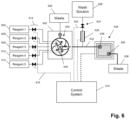
- FIG. 6 is a diagrammatic illustration of an exemplary apparatus using a fluidics system of the invention.
- FIG. 7 illustrates an embodiment providing separate wash control in a dual-flow chamber flow cell that provides an uninterrupted fluid path between a reference electrode and both chambers of the flow cell.
- the invention provides methods and apparatus for rapidly and cleanly switching flows of different fluids to a common outlet using a fluidics circuit.
- the fluidics circuit of the invention is combined with fluidic reservoirs, valves, pressure sources, pumps, control systems, and/or like components, to form a fluidics system for delivering separate fluid flows having predetermined rates and durations to a common volume, such as an outlet, chamber, flow cell, or the like.
- Such fluidics circuits are particularly useful in fluidics systems in apparatus for carrying out multi-step chemical, enzymatic, or electrochemical processes, such as described Margulies et al, Nature, 437: 376-380 (2005); Merrifield et al. U.S. Pat. No.
- the fluidics circuit of the invention provides a junction where a flow of a selected fluid is split into at least two branches: one branch is directed to an outlet and from there to a flow cell or reaction chamber for use and the other branch is directed past the unselected fluid inlets and from there away from the outlet and to a waste port.
- such flows are created by balancing the fluid resistance of the fluid outlet and that of the one or more passages between the fluid inlets and the waste port.
- the flow rates, fluid viscosities, compositions, and geometries and sizes of the passages, chambers and nodes are selected so that fluid flow is laminar within the fluidics circuit.
- Guidance for making such design choices is readily available from conventional treatises on fluid dynamics, e.g. Acheson, Elementary Fluid Dynamics (Clarendon Press, 1990), and from free or commercially available software for modeling fluidics systems, e.g. SolidWorks from Dassault Systems (Concord. MA); Flowmaster from Flow Master USA, Inc. (Glenview, IL); and OpenFOAM (open source code for computational fluid dynamics available on the world wide web, www.openefd.co.uk).
- Fluidic circuits and apparatus of the invention are particularly well suited for meso-scale and micro-scale fluidics systems, for example, fluidics systems having passage cross-sections in the range of tens of square microns to a few square millimeters, or having flow rates in the range of from a few nL/sec to a hundreds of ⁇ L/sec.
- the number of fluid flows controlled by fluidics circuits of the invention can vary widely.
- fluidics circuits of the invention control a plurality of flows in the range of from 2 to 12 different fluids, or in another aspect in the range of from 2 to 6 different fluids.
- FIG. 1 A The design and operation of one embodiment of the invention is partially illustrated in FIG. 1 A .
- Four fluid inlets, or reagent inputs, ( 100 , 102 , 104 , 106 ) are connected to fluidics node ( 108 ) and are in fluid communication with, and on an opposing surface to outlet ( 110 ).
- Valve ( 111 ) is shown open so that fluid passes through inlet ( 100 ) into fluidics node ( 108 ).
- a portion ( 124 ) of the fluid travels through a passage shown on the left, a portion ( 126 ) travels through a passage shown on the right, and a portion exits the fluidics node through outlet ( 110 ).
- the three fluid flows are laminar and the flow along the surface containing the fluid inlets exits the fluidic node in a period of time that is much less than the time it would take material from the unselected inlets (diffuse effluent ( 128 )) to diffuse to the opposing surface of the fluidics node. In this way, intermixing of the different input reagents that exit through outlet ( 110 ) is avoided.
- reagent inputs are selected by opening the valve corresponding to such reagent and closing all the other valves. As illustrated in this embodiment, valve ( 111 ) is open and valves ( 113 , 115 , and 117 ) are closed.
- FIGS. 1 B- 1 D further illustrate the operation of the above embodiment.
- inlets ( 100 , 102 , 104 , and 106 ) connect to fluidics node ( 108 ) on a surface opposite of outlet ( 110 ) and passages ( 130 and 132 ) connect fluidics node ( 108 ) to waste port ( 134 ).
- wash fluid inlet ( 140 ) which is connected to outlet ( 110 ) and in fluid communication with fluidics node ( 110 ).
- wash inlet valve (not shown) is opened and valve (not shown) of reagent inlet ( 104 ) is opened.
- a wash solution flows into outlet ( 110 ) and towards an application, e.g.
- flow cell containing a chip, as described in Rothberg et al (cited above), and towards fluidics node ( 108 ) where it combines with and constrains fluid from inlet ( 104 ) to flow into waste port ( 134 ).
- Exemplary flow rates and times are listed in the figure for a particular application described more fully below, but generally such rates and time are design choices that depend on a particular application.
- flow reagent mode
- the flow of wash solution is shut off and the sole flow emanates from inlet ( 104 ).
- the flow is split into three branches two traveling through passages ( 130 ) and ( 132 ) and one traveling through outlet ( 110 ).
- FIG. 1 C the flow of wash solution is shut off and the sole flow emanates from inlet ( 104 ).
- FIG. 1 C the flow of wash solution is shut off and the sole flow emanates from inlet ( 104 ).
- the flow is split into three branches two traveling through passages ( 130 ) and ( 132 ) and one traveling through outlet ( 110
- FIG. 2 illustrates diagrammatically in top and side views another embodiment of a fluidic circuit, which uses ring-shaped waste and resistive passages ( 206 and 208 , respectively) to accommodate a greater number of inlets ( 200 ) than the embodiment of FIGS. 1 A- 1 D .
- multiple inlets ( 200 ) connect to fluidics node ( 202 ) in a surface opposite to that connecting to outlet ( 204 ). Fluid flow from an inlet is split in fluidics node ( 202 ) so that a portion exits outlet ( 204 ) and the remainder exits ring-shaped passage ( 208 ), whose width ( 210 ) and height ( 212 ) are selected to provide fluidic resistance for appropriately splitting the input reagent flow.
- FIGS. 3 A- 3 C diagrammatically illustrate another embodiment of the fluidics circuit of the invention which accommodates five input reagents in a planar circuit structure.
- FIG. 3 A is a top view of a transparent body or housing ( 300 ) containing fluidic circuit ( 302 ).
- Housing ( 300 ) may be constructed from a variety of materials, including metals, glass, ceramics, plastics, or the like.
- Transparent materials include polycarbonate, polymethyl methacrylate, and the like.
- Inlets (or input ports) ( 304 , 306 , 308 , 310 , and 312 ) are connected by a passage to their respective connector slots ( 314 ) located on the bottom side of housing ( 300 ) (shown as double circles concentric with the inlets) from which reagents enter fluidic circuit ( 302 ).
- Inlets ( 304 , 306 , 308 , 310 , and 312 ) are in fluid communication with passages ( 305 , 307 , 309 , 311 , and 313 , respectively) which, in turn, are connected to curvilinear passages ( 324 , 326 , 328 , 330 , and 332 , respectively).
- Each curvilinear passage consists of two legs, such as ( 336 ) and ( 338 ), identified for curvilinear passage ( 324 ) at a “T” junction ( 335 ), also identified for only curvilinear passage ( 324 ).
- One leg is an inner leg (for example ( 338 )) which connects its respective inlet to node (or multi-use central port) ( 301 ) and the other leg is an outer leg (for example ( 336 )) which connects its respective inlet to waste passage (or ring) ( 340 ).
- the cross-sectional areas and lengths of the inner and outer legs of the curvilinear passages may be selected to achieve the desired balance of flows at the “T” junctions and at node ( 301 ).
- waste passage (or channel) ( 340 ) is in fluid communication with waste port ( 345 ) which connects to a waste reservoir (not shown) by connector slot ( 346 ) on the bottom side of body ( 300 ).
- Node ( 301 ) is in fluid communication with port ( 360 ) by passage ( 361 ) which in this embodiment is external to body ( 300 ) and is illustrated by a dashed line.
- passage ( 361 ) may be formed in body ( 300 ) so that connector slots for node ( 301 ) and port ( 360 ) are not required.
- Port ( 360 ) is connected by passage ( 363 ) to wash solution inlet ( 362 ), where a “T” junction is formed, and to connector slot ( 364 ) which, in turn, provides a conduit to a flow cell, reaction chamber, or the like.
- FIGS. 3 B and 3 C illustrate two of three modes of using the fluidics circuit to distribute fluids to a flow cell. The modes of operation are implemented by valves ( 350 ) associated with each of the input reagents and with the wash solution. In a first mode of operation (selected reagent valve open, all other reagent valves closed, wash solution valve closed) ( FIG.
- a selected reagent is delivered to a flow cell; in a second mode of operation (selected reagent valve open, all other reagent valves closed, wash solution valve open) ( FIG. 3 C ) the fluidic circuit is primed to deliver a selected reagent; and in a third mode of operation (all reagent valves closed wash solution valve open) (not shown), all passages in the fluidics circuit are washed.
- a valve ( 350 ) which can be opened to allow fluid to enter fluidic circuit ( 302 ) through its respective inlet (as shown for valve ( 352 )), or closed to prevent fluid from entering circuit ( 302 ) (as shown with all valves, except for ( 352 )).
- this second flow again splits into multiple flows, one of which exits node ( 301 ) through passage ( 361 ) and then to passage ( 363 ) and to a flow cell and the other flows to each of the passages connecting node ( 301 ) to the other inlets, and then to waste passage ( 340 ) and waste port ( 345 ).
- the latter flows pass the other inlets carrying any material diffusing or leaking therefrom and directing it to waste port ( 345 ).
- a sequence of different reagents may be directed to a flow cell by opening the valve of a selected reagent and simultaneously closing the valves of all of the non-selected reagents and the wash solution.
- such sequence may be implemented by a sequence of operating modes of the fluidics circuit such as: wash, prime reagent x 1 , deliver reagent x 1 , wash, prime reagent x 2 , deliver reagent x 2 , wash, and so on.
- the reagent priming mode of operation is illustrated in FIG. 3 C .
- As in the reagent delivery mode all reagent inlet valves are closed, except for the valve corresponding to the selected reagent.
- the wash solution valve is open and the relative pressure of the selected reagent flow and the wash solution flow is selected so that wash solution flows through passage ( 361 ) and into node ( 301 ) where it then exits through all the passages leading to waste passage ( 340 ), except for the passage leading to the selected reagent inlet.
- FIGS. 4 A- 4 B diagrammatically illustrates another embodiment of a planar fluidics circuit which accommodates four input reagents and whose design can accommodate further input reagents by stacking of the planar fluidics circuit and connecting their fluidics nodes.
- the topology and operation of the planar fluidics circuit of FIG. 4 A is equivalent to that of FIG. 3 A .
- Outlet ( 402 ) and waste passages ( 424 , 426 , 428 , and 430 ) connect a stack of planar fluidic circuits as illustrated in FIG. 4 B .
- FIG. 5 diagrammatically illustrates how fluidics circuits of the invention may be used in an electrochemical process requiring multiple reactants, including electrolytes used in such processes, and employing a reference electrode upstream of a reaction chamber. For stable reference voltages, it is desirable that the reference electrode contact no more than a single process reagent.
- Fluidics circuits of the invention provide a means of delivering a predetermined sequence of electrolytes through a common inlet of a reaction chamber while maintaining (i) uninterrupted fluid communication between the reaction chamber and a reference electrode, and (ii) contact of only a single electrolyte (i.e. a selected electrolyte) with the reference electrode. All of the other reagent or electrolytes (i.e.
- Planar fluidics circuit ( 500 ) as described in FIGS. 4 A- 4 B delivers a sequence of different reagents to reaction chamber ( 510 ) by passage ( 502 ). Flows of wash solution may be directed through passage ( 504 ) to “T” junction ( 512 ) and back to fluidics circuit ( 500 ) and to reaction chamber ( 510 ), as described above.
- a stable reference voltage may be provided to reaction chamber ( 510 ) by positioning reference electrode ( 506 ) in or adjacent to passage ( 504 ). In one embodiment, such reference electrode may be a metal tube forming a section of passage ( 504 ), as is illustrated in FIG. 5 .
- Reference electrode ( 506 ) is electrically connected to a reference voltage source ( 508 ).
- such an apparatus comprises a reaction vessel coupled to an electronic sensor for monitoring products in the reaction vessel: a fluidics system including a fluidics circuit of the invention for sequentially delivering a plurality of different electrolytes including a selected electrolyte to the reaction vessel: and a reference electrode in contact with the selected electrolyte for providing a reference voltage to the electronic sensor, the reference voltage being provided without the reference electrode contacting any unselected electrolytes.
- fluidic circuits of the invention may be fabrication by a variety of methods and materials. Factors to be considered in selecting materials include degree of chemical inertness required, operating conditions, e.g. temperature, and the like, volume of reagents to be delivered, whether or not a reference voltage is required, manufacturability, and the like.
- microfluidic fabrication techniques are well-suited for making fluidics circuits of the invention, and guidance for such techniques is readily available to one of ordinary skill in the art, e.g. Malloy, Plastic Part Design for Injection Molding: An Introduction (Hanser Gardner Publications, 1994); Herold et at, Editors, Lab-on-a-Chip Technology (Vol.
- Fluidics circuits of the invention are useful in electrochemical processes where multiple reagents are delivered to one or more reactors that are monitored with electronic sensors requiring a reference electrode. Exposure of a reference electrode to multiple reagents can introduce undesirable noise into the signals detected by the electronic sensors. Circumstances where this occurs are in methods and apparatus for carrying out label-free DNA sequencing, and in particular, pH-based DNA sequencing.
- label-free DNA sequencing including pH-based DNA sequencing, has been described in the literature, including the following references that are incorporated by reference: Rothberg et al, U.S. patent publication 2009/0026082; Anderson et al, Sensors and Actuators B Chem., 129: 79-86 (2008); Pourmand et al, Proc. Natl.
- DNA templates each having a primer and polymerase operably bound are loaded into reaction chambers (such as the microwells disclosed in Rothberg et al, cited above), after which repeated cycles of deoxynucleoside triphosphate (dNTP) addition and washing are carried out.
- dNTP deoxynucleoside triphosphate
- Such templates are typically attached as clonal populations to a solid support, such as a microparticle, bead, or the like, and such clonal populations are loaded into reaction chambers.
- the polymerase extends the primer by incorporating added dNTP only if the next base in the template is the complement of the added dNTP. If there is one complementary base, there is one incorporation, if two, there are two incorporations, if three, there are three incorporations, and so on. With each such incorporation there is a hydrogen ion released, and collectively a population of templates releasing hydrogen ions causing very slight changes the local pH of the reaction chamber which is detected by an electronic sensor.
- FIG. 6 diagrammatically illustrates an apparatus employing a fluidics circuit of the invention for carrying out pH-based nucleic acid sequencing in accordance with Rothberg et al (cited above).
- housing ( 600 ) containing fluidics circuit ( 602 ) is connected by inlets to reagent reservoirs ( 604 , 606 , 608 , 610 , and 612 ), to waste reservoir ( 620 ) and to flow cell ( 634 ) by passage ( 632 ) that connects fluidics node ( 630 ) to inlet ( 638 ) of flow cell ( 634 ).
- Reagents from reservoirs ( 604 , 606 , 608 , 610 , and 612 ) may be driven to fluidic circuit ( 602 ) by a variety of methods including pressure, pumps, such as syringe pumps, gravity feed, and the like, and are selected by control of valves ( 614 ), as described above.
- Control system ( 618 ) includes controllers for valves ( 614 ) that generate signals for opening and closing via electrical connection ( 616 ).
- Control system ( 618 ) also includes controllers for other components of the system, such as wash solution valve ( 624 ) connected thereto by ( 622 ), and reference electrode ( 628 ).
- Control system ( 618 ) may also include control and data acquisition functions for flow cell ( 634 ).
- fluidic circuit ( 602 ) delivers a sequence of selected reagents ( 1 , 2 , 3 , 4 , or 5 ) to flow cell ( 634 ) under programmed control of control system ( 618 ), such that in between selected reagent flows fluidics circuit ( 602 ) is primed and washed, and flow cell ( 634 ) is washed. Fluids entering flow cell ( 634 ) exit through outlet ( 640 ) and are deposited in waste container ( 636 ).
- FIG. 7 illustrates how the fluidics circuit design concepts may be used to make a plurality of separate flow chambers using a single large flow cell and sensor array, wherein reagent access to each flow chamber is separately controlled while still maintaining uninterrupted fluid pathways to the reference electrode for all sensors in all the flow chambers.
- FIG. 7 is a top view of flow cell ( 700 ) that has fluidics interface member ( 702 ) mounted on and is sealingly attached to a housing (not shown) that holds sensor array ( 704 ) and defines two flow chambers ( 703 ) and ( 705 ), each having separate inlets ( 706 and 708 , respectively) and separate diagonally opposed outlets ( 710 and 712 , respectively) that are each connected to a common source of reagents from a fluidics circuit via passages 730 and 735 for flow chamber 1 and 732 and 737 for flow chamber 2 , and to separate auxiliary wash reservoirs: 722 for flow chamber 1 and 724 for flow chamber 2 .
- Interior walls ( 714 , 716 , 718 and 720 ) formed by attachment of fluidics interface member ( 702 ) to the chip housing defines the flow paths through flow chambers ( 703 ) and ( 705 ) and exclude opposing corner regions ( 750 , 751 , 752 , and 753 ) from having contact with reagents passing through the flow chambers.
- valve ( 723 ) When valve ( 723 ) is open, wash solution from the auxiliary wash reservoir 1 ( 722 ) passes through passage ( 729 ), through valve ( 723 ), to passage ( 734 ), and to junction ( 731 ), where the flow splits between passage ( 735 ) and passage ( 741 ).
- the lengths and cross-sections of passages ( 735 ) and ( 734 ), and the driving forces of the wash solution and reagent are selected so that when valve ( 723 ) is open (as shown) solely wash solution enters flow chamber 1 and reagent from the fluidics circuit is directed solely to waste reservoir ( 744 ).
- valve ( 723 ) When valve ( 723 ) is closed, then no wash solution moves in passage ( 729 ) and there is no barrier to the flow of reagent from passage ( 730 ), to passage ( 735 ), to passage ( 741 ), and to flow chamber 1 .
- valve ( 725 ) when valve ( 725 ) is open, wash solution from the auxiliary wash reservoir 2 ( 724 ) passes through passage ( 743 ), through valve ( 725 ), to passage ( 736 ), and to junction ( 745 ), where the flow splits between passage ( 737 ) and passage ( 747 ).
- the lengths and cross-sections of passages ( 736 ) and ( 737 ), and the driving forces of the wash solution and reagent are selected so that when valve ( 725 ) is open solely wash solution enters flow chamber 2 and reagent from the fluidics circuit is directed solely to waste reservoir ( 744 ).
- valve ( 725 ) is closed (as shown), then no wash solution moves in passage ( 743 ) and there is no barrier to the flow of reagent from passage ( 732 ), to passage ( 737 ), to passage ( 747 ), and to flow chamber 2 .
- Microfluidics device means an integrated system of one or more chambers, ports, and channels that are interconnected and in fluid communication and designed for carrying out an analytical reaction or process, either alone or in cooperation with an appliance or instrument that provides support functions, such as sample introduction, fluid and/or reagent driving means, temperature control, detection systems, data collection and/or integration systems, and the like. Microfluidics devices may further include valves, pumps, and specialized functional coatings on interior walls, e.g. to prevent adsorption of sample components or reactants, facilitate reagent movement by electroosmosis, or the like.
- Such devices are usually fabricated in or as a solid substrate, which may be glass, plastic, or other solid polymeric materials, and typically have a planar format for ease of detecting and monitoring sample and reagent movement, especially via optical or electrochemical methods.
- a microfluidic device usually have cross-sectional dimensions of less than a few hundred square micrometers and passages typically have capillary dimensions, e.g. having maximal cross-sectional dimensions of from about 500 ⁇ m to about 0.1 ⁇ m.
- Microfluidics devices typically have volume capacities in the range of from 1 ⁇ m to a few nL, e.g. 10-100 nL.
Abstract
Description
Claims (20)
Priority Applications (1)
| Application Number | Priority Date | Filing Date | Title |
|---|---|---|---|
| US17/304,452 US11951474B2 (en) | 2008-10-22 | 2021-06-21 | Fluidics systems for sequential delivery of reagents |
Applications Claiming Priority (11)
| Application Number | Priority Date | Filing Date | Title |
|---|---|---|---|
| US19695308P | 2008-10-22 | 2008-10-22 | |
| US19822208P | 2008-11-04 | 2008-11-04 | |
| US20562609P | 2009-01-22 | 2009-01-22 | |
| US12/474,897 US20100137143A1 (en) | 2008-10-22 | 2009-05-29 | Methods and apparatus for measuring analytes |
| US12/475,311 US20100301398A1 (en) | 2009-05-29 | 2009-05-29 | Methods and apparatus for measuring analytes |
| US12/785,667 US8546128B2 (en) | 2008-10-22 | 2010-05-24 | Fluidics system for sequential delivery of reagents |
| US13/245,649 US8846378B2 (en) | 2008-10-22 | 2011-09-26 | Fluidics system for sequential delivery of reagents |
| US14/291,372 US9550183B2 (en) | 2008-10-22 | 2014-05-30 | Fluidics system for sequential delivery of reagents |
| US15/348,907 US10478816B2 (en) | 2008-10-22 | 2016-11-10 | Fluidics system for sequential delivery of reagents |
| US16/687,672 US11040344B2 (en) | 2008-10-22 | 2019-11-18 | Fluidics system for sequential delivery of reagents |
| US17/304,452 US11951474B2 (en) | 2008-10-22 | 2021-06-21 | Fluidics systems for sequential delivery of reagents |
Related Parent Applications (1)
| Application Number | Title | Priority Date | Filing Date |
|---|---|---|---|
| US16/687,672 Continuation US11040344B2 (en) | 2008-10-22 | 2019-11-18 | Fluidics system for sequential delivery of reagents |
Publications (2)
| Publication Number | Publication Date |
|---|---|
| US20210379588A1 US20210379588A1 (en) | 2021-12-09 |
| US11951474B2 true US11951474B2 (en) | 2024-04-09 |
Family
ID=78816890
Family Applications (1)
| Application Number | Title | Priority Date | Filing Date |
|---|---|---|---|
| US17/304,452 Active 2030-01-31 US11951474B2 (en) | 2008-10-22 | 2021-06-21 | Fluidics systems for sequential delivery of reagents |
Country Status (1)
| Country | Link |
|---|---|
| US (1) | US11951474B2 (en) |
Citations (51)
| Publication number | Priority date | Publication date | Assignee | Title |
|---|---|---|---|---|
| US3531258A (en) | 1967-11-16 | 1970-09-29 | Us Health Education & Welfare | Apparatus for the automated synthesis of peptides |
| US4008736A (en) | 1974-03-21 | 1977-02-22 | Wittmann Liebold Brigitte | Valve arrangement for distributing fluids |
| US4558845A (en) | 1982-09-22 | 1985-12-17 | Hunkapiller Michael W | Zero dead volume valve |
| US4722830A (en) | 1986-05-05 | 1988-02-02 | General Electric Company | Automated multiple stream analysis system |
| US5082788A (en) | 1986-08-27 | 1992-01-21 | Porton Instruments, Inc. | Method of sequencing peptides and proteins using a valve block assembly |
| US5126022A (en) | 1990-02-28 | 1992-06-30 | Soane Tecnologies, Inc. | Method and device for moving molecules by the application of a plurality of electrical fields |
| US5132418A (en) | 1980-02-29 | 1992-07-21 | University Patents, Inc. | Process for preparing polynucleotides |
| US5284566A (en) | 1993-01-04 | 1994-02-08 | Bacharach, Inc. | Electrochemical gas sensor with wraparound reference electrode |
| US5313984A (en) | 1992-09-24 | 1994-05-24 | Santa Barbara Research Center | Multi-fluid, variable sequence, zero dead volume valve and system |
| CN1105914A (en) | 1993-10-21 | 1995-08-02 | 摩根建造公司 | Coolant guard for rolling mill oil film bearing assebmly |
| US5498392A (en) | 1992-05-01 | 1996-03-12 | Trustees Of The University Of Pennsylvania | Mesoscale polynucleotide amplification device and method |
| US5587128A (en) | 1992-05-01 | 1996-12-24 | The Trustees Of The University Of Pennsylvania | Mesoscale polynucleotide amplification devices |
| WO1998049548A1 (en) | 1997-04-25 | 1998-11-05 | Caliper Technologies Corporation | Microfluidic devices incorporating improved channel geometries |
| WO1999019717A1 (en) | 1997-10-15 | 1999-04-22 | Aclara Biosciences, Inc. | Laminate microstructure device and method for making same |
| US6001299A (en) | 1995-02-21 | 1999-12-14 | Japan Vilene Company, Ltd. | Process and apparatus for manufacturing an electret article |
| US6010607A (en) | 1994-08-01 | 2000-01-04 | Lockheed Martin Energy Research Corporation | Apparatus and method for performing microfluidic manipulations for chemical analysis and synthesis |
| US6054034A (en) | 1990-02-28 | 2000-04-25 | Aclara Biosciences, Inc. | Acrylic microchannels and their use in electrophoretic applications |
| WO2002024322A2 (en) | 2000-09-19 | 2002-03-28 | Aclara Biosciences, Inc. | Microfluidic chip having integrated electrodes |
| US6399952B1 (en) | 1999-05-12 | 2002-06-04 | Aclara Biosciences, Inc. | Multiplexed fluorescent detection in microfluidic devices |
| US20020076825A1 (en) | 2000-10-10 | 2002-06-20 | Jing Cheng | Integrated biochip system for sample preparation and analysis |
| US20020187074A1 (en) | 2001-06-07 | 2002-12-12 | Nanostream, Inc. | Microfluidic analytical devices and methods |
| US6499499B2 (en) | 2001-04-20 | 2002-12-31 | Nanostream, Inc. | Flow control in multi-stream microfluidic devices |
| US6613525B2 (en) | 1996-07-30 | 2003-09-02 | Aclara Biosciences, Inc. | Microfluidic apparatus and method for purification and processing |
| CN1472526A (en) | 2002-07-31 | 2004-02-04 | 中国科学院生态环境研究中心 | Tunnel capillary electrophoretic chemiluminescence testing microfluid control chip |
| US20040072278A1 (en) | 2002-04-01 | 2004-04-15 | Fluidigm Corporation | Microfluidic particle-analysis systems |
| US20040096368A1 (en) | 2002-06-28 | 2004-05-20 | Igen International, Inc. | Assay systems and components |
| US20040146849A1 (en) | 2002-01-24 | 2004-07-29 | Mingxian Huang | Biochips including ion transport detecting structures and methods of use |
| WO2005016536A1 (en) | 2003-08-04 | 2005-02-24 | Caliper Life Sciences, Inc. | Methods and systems for processing microscale devices for reuse |
| US20050100939A1 (en) | 2003-09-18 | 2005-05-12 | Eugeni Namsaraev | System and methods for enhancing signal-to-noise ratios of microarray-based measurements |
| JP2005519751A (en) | 2002-03-14 | 2005-07-07 | マイクロニクス, インコーポレイテッド | Microfluidic channel network device |
| US20050202504A1 (en) | 1995-06-29 | 2005-09-15 | Affymetrix, Inc. | Miniaturized genetic analysis systems and methods |
| US6960437B2 (en) | 2001-04-06 | 2005-11-01 | California Institute Of Technology | Nucleic acid amplification utilizing microfluidic devices |
| US20050272159A1 (en) | 2002-05-09 | 2005-12-08 | Ismagilov Rustem F | Device and method for pressure-driven plug transport and reaction |
| US20060094588A1 (en) | 2003-03-20 | 2006-05-04 | Gibson Vernon C | Polymerisation and oligomerisation catalysts |
| US20060182664A1 (en) | 2005-02-14 | 2006-08-17 | Peck Bill J | Flow cell devices, systems and methods of using the same |
| US20060223178A1 (en) | 2005-04-05 | 2006-10-05 | Tom Barber | Devices and methods for magnetic enrichment of cells and other particles |
| CN2831115Y (en) | 2005-05-19 | 2006-10-25 | 复旦大学 | Multi-channel microflow controlled chip |
| WO2007047336A2 (en) | 2005-10-12 | 2007-04-26 | University Of Virginia Patent Foundation | Integrated microfluidic analysis systems |
| US20070117099A1 (en) | 2005-11-18 | 2007-05-24 | Mei Technologies, Inc. | Process and apparatus for combinatorial synthesis |
| WO2007106579A2 (en) | 2006-03-15 | 2007-09-20 | Micronics, Inc. | Integrated nucleic acid assays |
| US20070217963A1 (en) | 2005-09-29 | 2007-09-20 | Elizarov Arkadij M | Microfluidic chip capable of synthesizing radioactively labeled molecules on a scale suitable for human imaging with positron emission tomography |
| US20090008253A1 (en) | 2004-06-04 | 2009-01-08 | Crystal Vision Microsystems Llc | Device and Process for Continuous On-Chip Flow Injection Analysis |
| US20090026082A1 (en) | 2006-12-14 | 2009-01-29 | Ion Torrent Systems Incorporated | Methods and apparatus for measuring analytes using large scale FET arrays |
| US7534097B2 (en) | 2004-10-15 | 2009-05-19 | Nanyang Technological University | Method and apparatus for controlling multi-fluid flow in a micro channel |
| US20090127589A1 (en) | 2006-12-14 | 2009-05-21 | Ion Torrent Systems Incorporated | Methods and apparatus for measuring analytes using large scale FET arrays |
| WO2009119698A1 (en) | 2008-03-24 | 2009-10-01 | 日本電気株式会社 | Flow passage control mechanism for microchip |
| US20100137143A1 (en) | 2008-10-22 | 2010-06-03 | Ion Torrent Systems Incorporated | Methods and apparatus for measuring analytes |
| WO2010138186A1 (en) | 2009-05-29 | 2010-12-02 | Ion Torrent Systems Incorporated | Fluidics system for sequential delivery of reagents |
| US7888015B2 (en) | 2001-03-09 | 2011-02-15 | Dna Electronics Ltd. | qPCR using solid-state sensing |
| JP2011527012A (en) | 2008-06-30 | 2011-10-20 | キヤノン ユー.エス. ライフ サイエンシズ, インコーポレイテッド | System and method for preventing cross-contamination in an assay performed in a microfluidic channel |
| US20120143531A1 (en) | 2010-01-07 | 2012-06-07 | Life Technologies Corporation | Fluidics interface systems and methods |
-
2021
- 2021-06-21 US US17/304,452 patent/US11951474B2/en active Active
Patent Citations (56)
| Publication number | Priority date | Publication date | Assignee | Title |
|---|---|---|---|---|
| US3531258A (en) | 1967-11-16 | 1970-09-29 | Us Health Education & Welfare | Apparatus for the automated synthesis of peptides |
| US4008736A (en) | 1974-03-21 | 1977-02-22 | Wittmann Liebold Brigitte | Valve arrangement for distributing fluids |
| US5132418A (en) | 1980-02-29 | 1992-07-21 | University Patents, Inc. | Process for preparing polynucleotides |
| US4558845A (en) | 1982-09-22 | 1985-12-17 | Hunkapiller Michael W | Zero dead volume valve |
| US4722830A (en) | 1986-05-05 | 1988-02-02 | General Electric Company | Automated multiple stream analysis system |
| US5082788A (en) | 1986-08-27 | 1992-01-21 | Porton Instruments, Inc. | Method of sequencing peptides and proteins using a valve block assembly |
| US5126022A (en) | 1990-02-28 | 1992-06-30 | Soane Tecnologies, Inc. | Method and device for moving molecules by the application of a plurality of electrical fields |
| US6054034A (en) | 1990-02-28 | 2000-04-25 | Aclara Biosciences, Inc. | Acrylic microchannels and their use in electrophoretic applications |
| US5498392A (en) | 1992-05-01 | 1996-03-12 | Trustees Of The University Of Pennsylvania | Mesoscale polynucleotide amplification device and method |
| US5587128A (en) | 1992-05-01 | 1996-12-24 | The Trustees Of The University Of Pennsylvania | Mesoscale polynucleotide amplification devices |
| US5313984A (en) | 1992-09-24 | 1994-05-24 | Santa Barbara Research Center | Multi-fluid, variable sequence, zero dead volume valve and system |
| US5284566A (en) | 1993-01-04 | 1994-02-08 | Bacharach, Inc. | Electrochemical gas sensor with wraparound reference electrode |
| CN1105914A (en) | 1993-10-21 | 1995-08-02 | 摩根建造公司 | Coolant guard for rolling mill oil film bearing assebmly |
| US6010607A (en) | 1994-08-01 | 2000-01-04 | Lockheed Martin Energy Research Corporation | Apparatus and method for performing microfluidic manipulations for chemical analysis and synthesis |
| US6033546A (en) | 1994-08-01 | 2000-03-07 | Lockheed Martin Energy Research Corporation | Apparatus and method for performing microfluidic manipulations for chemical analysis and synthesis |
| US6001299A (en) | 1995-02-21 | 1999-12-14 | Japan Vilene Company, Ltd. | Process and apparatus for manufacturing an electret article |
| US20050202504A1 (en) | 1995-06-29 | 2005-09-15 | Affymetrix, Inc. | Miniaturized genetic analysis systems and methods |
| US6613525B2 (en) | 1996-07-30 | 2003-09-02 | Aclara Biosciences, Inc. | Microfluidic apparatus and method for purification and processing |
| WO1998049548A1 (en) | 1997-04-25 | 1998-11-05 | Caliper Technologies Corporation | Microfluidic devices incorporating improved channel geometries |
| WO1999019717A1 (en) | 1997-10-15 | 1999-04-22 | Aclara Biosciences, Inc. | Laminate microstructure device and method for making same |
| US6399952B1 (en) | 1999-05-12 | 2002-06-04 | Aclara Biosciences, Inc. | Multiplexed fluorescent detection in microfluidic devices |
| WO2002024322A2 (en) | 2000-09-19 | 2002-03-28 | Aclara Biosciences, Inc. | Microfluidic chip having integrated electrodes |
| US20020076825A1 (en) | 2000-10-10 | 2002-06-20 | Jing Cheng | Integrated biochip system for sample preparation and analysis |
| US7888015B2 (en) | 2001-03-09 | 2011-02-15 | Dna Electronics Ltd. | qPCR using solid-state sensing |
| US6960437B2 (en) | 2001-04-06 | 2005-11-01 | California Institute Of Technology | Nucleic acid amplification utilizing microfluidic devices |
| US6499499B2 (en) | 2001-04-20 | 2002-12-31 | Nanostream, Inc. | Flow control in multi-stream microfluidic devices |
| US20020187074A1 (en) | 2001-06-07 | 2002-12-12 | Nanostream, Inc. | Microfluidic analytical devices and methods |
| US20040146849A1 (en) | 2002-01-24 | 2004-07-29 | Mingxian Huang | Biochips including ion transport detecting structures and methods of use |
| US7223371B2 (en) | 2002-03-14 | 2007-05-29 | Micronics, Inc. | Microfluidic channel network device |
| JP2005519751A (en) | 2002-03-14 | 2005-07-07 | マイクロニクス, インコーポレイテッド | Microfluidic channel network device |
| US20040224380A1 (en) | 2002-04-01 | 2004-11-11 | Fluidigm Corp. | Microfluidic particle-analysis systems |
| US20040072278A1 (en) | 2002-04-01 | 2004-04-15 | Fluidigm Corporation | Microfluidic particle-analysis systems |
| US20050272159A1 (en) | 2002-05-09 | 2005-12-08 | Ismagilov Rustem F | Device and method for pressure-driven plug transport and reaction |
| US20040096368A1 (en) | 2002-06-28 | 2004-05-20 | Igen International, Inc. | Assay systems and components |
| CN1472526A (en) | 2002-07-31 | 2004-02-04 | 中国科学院生态环境研究中心 | Tunnel capillary electrophoretic chemiluminescence testing microfluid control chip |
| US20060094588A1 (en) | 2003-03-20 | 2006-05-04 | Gibson Vernon C | Polymerisation and oligomerisation catalysts |
| JP2006524797A (en) | 2003-08-04 | 2006-11-02 | カリパー・ライフ・サイエンシズ・インク. | Method and system for processing microscale devices for reuse |
| WO2005016536A1 (en) | 2003-08-04 | 2005-02-24 | Caliper Life Sciences, Inc. | Methods and systems for processing microscale devices for reuse |
| US20050100939A1 (en) | 2003-09-18 | 2005-05-12 | Eugeni Namsaraev | System and methods for enhancing signal-to-noise ratios of microarray-based measurements |
| US20090008253A1 (en) | 2004-06-04 | 2009-01-08 | Crystal Vision Microsystems Llc | Device and Process for Continuous On-Chip Flow Injection Analysis |
| US7534097B2 (en) | 2004-10-15 | 2009-05-19 | Nanyang Technological University | Method and apparatus for controlling multi-fluid flow in a micro channel |
| US20060182664A1 (en) | 2005-02-14 | 2006-08-17 | Peck Bill J | Flow cell devices, systems and methods of using the same |
| US20060223178A1 (en) | 2005-04-05 | 2006-10-05 | Tom Barber | Devices and methods for magnetic enrichment of cells and other particles |
| CN2831115Y (en) | 2005-05-19 | 2006-10-25 | 复旦大学 | Multi-channel microflow controlled chip |
| US20070217963A1 (en) | 2005-09-29 | 2007-09-20 | Elizarov Arkadij M | Microfluidic chip capable of synthesizing radioactively labeled molecules on a scale suitable for human imaging with positron emission tomography |
| WO2007047336A2 (en) | 2005-10-12 | 2007-04-26 | University Of Virginia Patent Foundation | Integrated microfluidic analysis systems |
| US20070117099A1 (en) | 2005-11-18 | 2007-05-24 | Mei Technologies, Inc. | Process and apparatus for combinatorial synthesis |
| WO2007106579A2 (en) | 2006-03-15 | 2007-09-20 | Micronics, Inc. | Integrated nucleic acid assays |
| US20090127589A1 (en) | 2006-12-14 | 2009-05-21 | Ion Torrent Systems Incorporated | Methods and apparatus for measuring analytes using large scale FET arrays |
| US20090026082A1 (en) | 2006-12-14 | 2009-01-29 | Ion Torrent Systems Incorporated | Methods and apparatus for measuring analytes using large scale FET arrays |
| WO2009119698A1 (en) | 2008-03-24 | 2009-10-01 | 日本電気株式会社 | Flow passage control mechanism for microchip |
| JP2011527012A (en) | 2008-06-30 | 2011-10-20 | キヤノン ユー.エス. ライフ サイエンシズ, インコーポレイテッド | System and method for preventing cross-contamination in an assay performed in a microfluidic channel |
| US20100137143A1 (en) | 2008-10-22 | 2010-06-03 | Ion Torrent Systems Incorporated | Methods and apparatus for measuring analytes |
| US20200086317A1 (en) | 2008-10-22 | 2020-03-19 | Life Technologies Corporation | Fluidics system for sequential delivery of reagents |
| WO2010138186A1 (en) | 2009-05-29 | 2010-12-02 | Ion Torrent Systems Incorporated | Fluidics system for sequential delivery of reagents |
| US20120143531A1 (en) | 2010-01-07 | 2012-06-07 | Life Technologies Corporation | Fluidics interface systems and methods |
Non-Patent Citations (9)
| Title |
|---|
| Anderson, et al., "A system for multiplexed direct electrical detection of DNA synthesis", Sensors and Actuators B: Chemical, vol. 129, No. 1, Jan. 2008, pp. 79-86. |
| Brenner, et al., "Gene expression analysis by massively parallel signature sequencing (MPSS) on microbead arrays", Nature Biotechnology, vol. 18, No. 6, Jun. 2000, pp. 630-634. |
| Ep10780933, Search Report, dated Jun. 26, 2015, 2 pages. |
| Margulies et al., "Genome Sequencing in Microfabricated High-Density Picolitre Reactors", Nature, vol. 437, No. 15, 2005, pp. 376-380. |
| PCT/US2010/001547, Search Report and Written Opinion, dated Aug. 5, 2010. |
| Pourmand et al., "Direct electrical detection of DNA synthesis", Proceedings of the National Academy of Sciences, vol. 103, No. 17, Apr. 2006, pp. 6466-6470. |
| Ronaghi et al., "A Sequencing Method Based on Real-Time Pyrophosphate", Science, vol. 281, No. 5375, Jul. 1998, pp. 363-365. |
| Sia et al., "Microfluidic devices fabricated in poly(dimethylsiloxane) for biological studies", Electrophoresis, vol. 24, No. 21, Nov. 2003, pp. 3563-3576. |
| Unger et al., "Monolithic Microfabricated Valves and Pumps by Multilayer Soft Lithography", Science, vol. 288, No. 5463, Apr. 2000, pp. 113-116. |
Also Published As
| Publication number | Publication date |
|---|---|
| US20210379588A1 (en) | 2021-12-09 |
Similar Documents
| Publication | Publication Date | Title |
|---|---|---|
| US11040344B2 (en) | Fluidics system for sequential delivery of reagents | |
| US20230101252A1 (en) | Apparatus and methods for performing electrochemical reactions | |
| US6857449B1 (en) | Multi-layer microfluidic devices | |
| US6321791B1 (en) | Multi-layer microfluidic devices | |
| US7208320B2 (en) | Open-field serial to parallel converter | |
| Bousse et al. | Electrokinetically controlled microfluidic analysis systems | |
| Melin et al. | Microfluidic large-scale integration: the evolution of design rules for biological automation | |
| US20020009392A1 (en) | Methods of reducing fluid carryover in microfluidic devices | |
| GB2392397A (en) | Fluid focussing in a microfluidic device | |
| US11951474B2 (en) | Fluidics systems for sequential delivery of reagents | |
| US11123728B2 (en) | Fast sample loading microfluidic reactor and system | |
| KR100661930B1 (en) | Plastic chip for enzyme assay in microfluidic channels and methods for enzyme activity measurement using thereof | |
| KR102013996B1 (en) | Product method of lab on a chip | |
| Li | Jose L. Garcia-Cordero 2 and Antonio J. Ricco 2 Contact Information |
Legal Events
| Date | Code | Title | Description |
|---|---|---|---|
| AS | Assignment |
Owner name: ION TORRENT SYSTEMS, INC., CALIFORNIA Free format text: ASSIGNMENT OF ASSIGNORS INTEREST;ASSIGNORS:SCHULTZ, JONATHAN;MARRAN, DAVID;REEL/FRAME:057325/0814 Effective date: 20100622 |
|
| STPP | Information on status: patent application and granting procedure in general |
Free format text: DOCKETED NEW CASE - READY FOR EXAMINATION |
|
| STPP | Information on status: patent application and granting procedure in general |
Free format text: NON FINAL ACTION MAILED |
|
| STPP | Information on status: patent application and granting procedure in general |
Free format text: RESPONSE TO NON-FINAL OFFICE ACTION ENTERED AND FORWARDED TO EXAMINER |
|
| STPP | Information on status: patent application and granting procedure in general |
Free format text: FINAL REJECTION MAILED |
|
| STPP | Information on status: patent application and granting procedure in general |
Free format text: RESPONSE AFTER FINAL ACTION FORWARDED TO EXAMINER |
|
| STPP | Information on status: patent application and granting procedure in general |
Free format text: NOTICE OF ALLOWANCE MAILED -- APPLICATION RECEIVED IN OFFICE OF PUBLICATIONS |
|
| STCF | Information on status: patent grant |
Free format text: PATENTED CASE |