WO2023286867A1 - プレス用金型 - Google Patents
プレス用金型 Download PDFInfo
- Publication number
- WO2023286867A1 WO2023286867A1 PCT/JP2022/027929 JP2022027929W WO2023286867A1 WO 2023286867 A1 WO2023286867 A1 WO 2023286867A1 JP 2022027929 W JP2022027929 W JP 2022027929W WO 2023286867 A1 WO2023286867 A1 WO 2023286867A1
- Authority
- WO
- WIPO (PCT)
- Prior art keywords
- rib
- mold
- ribs
- view
- plan
- Prior art date
- Legal status (The legal status is an assumption and is not a legal conclusion. Google has not performed a legal analysis and makes no representation as to the accuracy of the status listed.)
- Ceased
Links
Images


Classifications
-
- B—PERFORMING OPERATIONS; TRANSPORTING
- B21—MECHANICAL METAL-WORKING WITHOUT ESSENTIALLY REMOVING MATERIAL; PUNCHING METAL
- B21D—WORKING OR PROCESSING OF SHEET METAL OR METAL TUBES, RODS OR PROFILES WITHOUT ESSENTIALLY REMOVING MATERIAL; PUNCHING METAL
- B21D22/00—Shaping without cutting, by stamping, spinning, or deep-drawing
- B21D22/02—Stamping using rigid devices or tools
-
- B—PERFORMING OPERATIONS; TRANSPORTING
- B21—MECHANICAL METAL-WORKING WITHOUT ESSENTIALLY REMOVING MATERIAL; PUNCHING METAL
- B21D—WORKING OR PROCESSING OF SHEET METAL OR METAL TUBES, RODS OR PROFILES WITHOUT ESSENTIALLY REMOVING MATERIAL; PUNCHING METAL
- B21D22/00—Shaping without cutting, by stamping, spinning, or deep-drawing
- B21D22/20—Deep-drawing
-
- B—PERFORMING OPERATIONS; TRANSPORTING
- B21—MECHANICAL METAL-WORKING WITHOUT ESSENTIALLY REMOVING MATERIAL; PUNCHING METAL
- B21D—WORKING OR PROCESSING OF SHEET METAL OR METAL TUBES, RODS OR PROFILES WITHOUT ESSENTIALLY REMOVING MATERIAL; PUNCHING METAL
- B21D37/00—Tools as parts of machines covered by this subclass
-
- B—PERFORMING OPERATIONS; TRANSPORTING
- B21—MECHANICAL METAL-WORKING WITHOUT ESSENTIALLY REMOVING MATERIAL; PUNCHING METAL
- B21D—WORKING OR PROCESSING OF SHEET METAL OR METAL TUBES, RODS OR PROFILES WITHOUT ESSENTIALLY REMOVING MATERIAL; PUNCHING METAL
- B21D37/00—Tools as parts of machines covered by this subclass
- B21D37/10—Die sets; Pillar guides
-
- B—PERFORMING OPERATIONS; TRANSPORTING
- B29—WORKING OF PLASTICS; WORKING OF SUBSTANCES IN A PLASTIC STATE IN GENERAL
- B29C—SHAPING OR JOINING OF PLASTICS; SHAPING OF MATERIAL IN A PLASTIC STATE, NOT OTHERWISE PROVIDED FOR; AFTER-TREATMENT OF THE SHAPED PRODUCTS, e.g. REPAIRING
- B29C51/00—Shaping by thermoforming, i.e. shaping sheets or sheet like preforms after heating, e.g. shaping sheets in matched moulds or by deep-drawing; Apparatus therefor
- B29C51/26—Component parts, details or accessories; Auxiliary operations
- B29C51/30—Moulds
-
- B—PERFORMING OPERATIONS; TRANSPORTING
- B21—MECHANICAL METAL-WORKING WITHOUT ESSENTIALLY REMOVING MATERIAL; PUNCHING METAL
- B21D—WORKING OR PROCESSING OF SHEET METAL OR METAL TUBES, RODS OR PROFILES WITHOUT ESSENTIALLY REMOVING MATERIAL; PUNCHING METAL
- B21D37/00—Tools as parts of machines covered by this subclass
- B21D37/01—Selection of materials
-
- B—PERFORMING OPERATIONS; TRANSPORTING
- B21—MECHANICAL METAL-WORKING WITHOUT ESSENTIALLY REMOVING MATERIAL; PUNCHING METAL
- B21D—WORKING OR PROCESSING OF SHEET METAL OR METAL TUBES, RODS OR PROFILES WITHOUT ESSENTIALLY REMOVING MATERIAL; PUNCHING METAL
- B21D37/00—Tools as parts of machines covered by this subclass
- B21D37/20—Making tools by operations not covered by a single other subclass
Definitions
- the present invention relates to a press die attached to a press.
- Press molding of metal sheets is widely used in the manufacture of automobiles, machinery, electrical equipment, transportation equipment, etc., due to its high productivity, excellent dimensional accuracy, small variations in strength between products, and stable quality. This is the most common processing method used.
- the press molding machine has a fixed lower mold and an upper mold that moves up and down by the press. Since the upper mold is required to have high rigidity from the viewpoint of press workability, conventionally, not only the processed surface but also the entire back surface has been a solid block shape (for example, Patent Document 1).
- the main object of the present invention is to provide a mold that is lightweight and has sufficient rigidity.
- a press die that solves the above problems has the following features.
- a mold used in a press machine comprising a lower mold provided below in the height direction, an upper mold provided above, and a press mechanism for moving the upper mold up and down,
- the mold has a frame portion, a processing surface portion, and ribs intersecting the processing surface portion,
- a plurality of segments are formed by a combination of the rib, or the rib and the frame, and the space surrounded by the rib,
- a press die characterized by:
- the vertical forming load applied to the processing surface is supported by a plurality of segments formed by a combination of the ribs or the ribs and the frame and the space surrounded by the ribs, and the compressive load during forming is applied.
- An outward horizontal load acting on the mold can be supported by the frame.
- weight reduction can be achieved by the space of the formed segment.
- a mode is proposed in which the segment has a first rib extending in a first direction in plan view and a plurality of second ribs intersecting with the first rib. Since the first ribs intersect the plurality of second ribs and extend in the first direction, the rigidity against bending in the first direction is high.
- the first rib is along the curved portion of the machined surface portion, that is, the direction in which the first rib extends coincides with the direction in which the curved portion of the machined surface portion extends. A bending load can be supported by the first rib.
- each rib When the third rib is formed on the other mold corresponding to the first rib, each rib can withstand a large bending load, and bending can be performed reliably.
- the segments When at least one of the segments has a honeycomb shape in a plan view, it is possible to efficiently support the pressing load on the machined surface and the crushing load due to compression directed horizontally outward, and at the same time, it is possible to increase the volume ratio occupied by the space and reduce the weight. In addition, the rigidity against pressing load (longitudinal load) is high.
- the curved portion which is subject to large strain due to processing, is formed by a separate block made of a material different from that of the main body. By making it possible, it is convenient in terms of maintenance.
- the outward collapse deformation of the frame due to the outward horizontal load acting on the mold due to the compressive load during molding is suppressed. It can be suitably suppressed.
- the curvature of the arc-shaped portion of the corner along the direction in which the rib and the processed surface portion are continuous which does not require emphasis on collapse deformation, is made relatively smaller than the curvature of the arc-shaped portion on the frame side. , the volume of the space will be increased accordingly, contributing to weight reduction.
- the outward opening deformation of the frame due to the outward horizontal load acting on the mold due to the compressive load during molding can be suitably suppressed in the extending direction of the intermediate ribs.
- the intermediate ribs in the height direction have side concave portions on the upper and lower sides respectively.
- the formation of intermediate ribs increases the weight of the mold, but the formation of side recesses on the upper and lower sides reduces the weight of the mold. Rigidity can be increased while suppressing.
- the intermediate ribs surround the corners of the mold and encircle the entire circumference including the front and rear surfaces and the left and right surfaces of the frame.
- the side concave portions are formed at least on the front and rear surfaces and the left and right surfaces of the frame portion excluding the corner portions. Since the corner portion of the mold is a portion that ensures rigidity against the press load as a column, the formation of side concave portions that result in a reduction in the thickness of the frame portion should be suppressed as much as possible.
- At least one segment exhibiting a honeycomb shape is formed in the central portion of the mold in plan view, and a segment different from the honeycomb shape is formed in the peripheral portion of the mold in plan view. It is possible to maximize the associated benefits.
- FIG. 11 is a plan view of another mold; It is a top view of another metallic mold.
- FIG. 11 is a perspective view of still another mold example; It is a plan view of a different mold. It is a plan view of a further different mold. It is a top view of another metallic mold.
- FIG. 11 is a plan view of still another mold; 1 is a front view partially showing a schematic example of a press; FIG. FIG. 10 is an explanatory diagram of simulation evaluation results; It is a top view of the 1st example of a combination shape. It is a top view of the 2nd example of a combined shape.
- FIG. 4 is a perspective view of an example of an upper mold having a different aspect
- FIG. 10 is a perspective view of an example upper mold without intermediate ribs
- 19-19 line arrow view is a perspective view of an example upper mold having intermediate ribs
- 21-21 is a line view.
- a press machine includes a lower mold provided below in the height direction, an upper mold provided above, and a press mechanism for moving the upper mold up and down.
- a cold press molding device 11 shown in FIG. 11 can be cited. It may be a hot press molding device.
- a press molding device 11 molds a metal plate material 12 and has a molding section including a lower mold 13 and an upper mold 14 .
- the front side of the paper will be referred to as the front side
- the back side of the paper will be referred to as the rear side.
- the front and back are also referred to as the X direction, the left and right as the Y direction, and the height direction as the Z direction.
- the first direction the other is the second direction.
- the lower mold 13 is attached to a base (bolster) 24 of the molding section via a lower mold holder 23 .
- a plurality of vertically extending guide rods 25 are erected on the base 24 .
- the upper mold 14 is attached to an upper mold holder (slide) 26 .
- the upper die holder 26 is supported by the guide rod 25 so as to be vertically movable.
- the upper die holder 26 is connected to a pressure device (not shown) and driven by the pressure device to move vertically.
- the upper mold 14 attached to the upper mold holder 26 moves vertically between, for example, the molding position shown in FIG. 3 and the retracted position shown in FIG. 11 as the upper mold holder 26 moves up and down.
- the press mechanism is configured in this manner.
- molding the metal plate material 12 examples include molding a metal plate for an automobile body, especially molding a high-tensile (high-tensile) metal plate (for example, a high-tensile steel plate).
- high-tensile high-tensile steel plate
- the upper and lower dies are required to have high rigidity from the viewpoint of press workability. rice field.
- the configuration according to the present invention only needs to be provided in one of the upper mold and the lower mold.
- the structure of the embodiment will be mainly described with respect to the upper mold, and the lower mold will also be explained as necessary.
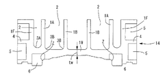
- a concave portion (space) 2 partitioned by a frame portion 1F, a weighting rib 1A, and a second rib 1B is formed on the side opposite to the processing surface portion 1W including the processing surface, and a plurality of segments are used.
- a third rib 1C is formed on the lower mold (see FIG. 3).
- FIG. 14A Regular grid mold 14A having regular grid ribs 1B in plan view shown in FIG. (2)
- a slanted lattice mold 14B having slanted lattice ribs 1B in plan view shown in FIG. (3)
- a honeycomb-shaped mold 14C having ribs 1B in a honeycomb shape in a perspective view shown in FIG. (4)
- a truss-shaped mold 14D having truss-shaped ribs 1B in plan view shown in FIG. (5)
- a circular mold 14E having ribs 1B having circular recesses in plan view shown in FIG.
- the mold has a frame portion 1F, a processing surface portion 1W, and ribs intersecting the processing surface portion 1W, and a concave portion (space) 2 surrounded by the ribs,
- a plurality of segments are formed by a combination of ribs and frame portions 1F and concave portions (spaces) 2 surrounded by them.
- the frame portion 1F, the processed surface portion 1W, and the processed surface portion 1W are formed continuously and integrally.
- the ribs partition adjacent recesses (spaces) 2, and the number of segments corresponding to the number of recesses (spaces) 2 is formed.
- Segments take various forms. 1 and 3, a weighting rib 1A continuously extending in a first direction (the X direction in FIG. 1) in plan view, and a plurality of second ribs 1B intersecting with the weighting rib 1A. There is a segment having a concave portion (space) 2 together with the frame portion 1F. In addition, there is a segment having a concave portion (space) 2 formed by the weighting rib 1A and the plurality of second ribs 1B. Furthermore, the second ribs 1B may not intersect the weighting ribs 1A, and the combination of a plurality of the second ribs 1B may constitute a segment having a recess (space) 2. FIG.
- the weighting rib 1A extends in the first direction (X direction in FIG. 1).
- extending in the first direction means that in addition to extending in a straight line, it may extend in the first direction (the X direction in FIG. 1) as a whole, even though it has a curved shape or steps. This also means that aligned ones are included.
- Such weighting ribs 1A are provided, for example, in order to partially (weight) increase the rigidity of a honeycomb mold 14C forming a honeycomb by only the second ribs 1B, as shown in FIG. to form.
- the significance of the weighting rib 1A is not only that it is “along the first direction", but also that it "forms a predetermined shape (for example, forms a honeycomb shape) in order to partially increase the rigidity. It is a rib that satisfies both conditions that the rib is formed by weighting. Therefore, for example, in the example of the regular lattice mold 14A shown in FIG. 4, the condition that the ribs are "along the first direction" is satisfied, but the latter condition that the ribs are "formed in a weighted manner" is fulfilled. Since it does not meet the conditions, it is not called the weighted rib 1A.
- This honeycomb mold 14C1 has many segments on the back side. That is, a weighting rib 1A extending in a first direction (the X direction in FIG. 1), a plurality of second ribs 1B intersecting with the weighting rib 1A, and a frame portion 1F have segments having recesses (spaces) 2. As shown in FIG. It also has a segment that does not intersect with the frame portion 1F and forms a concave portion (space) 2 with the weighting rib 1A and the plurality of second ribs 1B. Further, the second ribs 1B may not intersect with the frame portion 1F and the weighting ribs 1A, and the combination of a plurality of the second ribs 1B may constitute a segment having the concave portion (space) 2 .
- FIGS. 2 and 3 show an example of bending and press-molding the automobile metal plate 12 (see FIG. 11) with the upper mold 14 and the lower mold 13.
- FIG. 11 shows an example of bending and press-molding the automobile metal plate 12 (see FIG. 11) with the upper mold 14 and the lower mold 13.
- the outer peripheral surface of the frame portion 1F of the upper mold 14 circulates around the entire circumference including the frame portion 1F.
- Intermediate ribs 4 are formed (on the front and rear surfaces and on the left and right surfaces) (illustration of the intermediate ribs 4 is omitted in FIG. 1). According to this aspect, the outward collapse deformation of the frame portion due to the outward horizontal load acting on the mold due to the compressive load during molding can be suitably suppressed in the extending direction of the intermediate ribs. Further, the formation of the intermediate ribs 4 can ensure the rigidity, and the formation of the side recesses 5 can reduce the weight.
- the recess (space) 2 is also formed in the lower mold 15 .
- high-strength upper die inserts (blocks) 6 made of a material different from that of the upper die 14 are provided on both sides of the machined surface portion 1W of the upper die 14 .
- Blank holder inserts (blocks) 15 made of a material different from that of the lower mold 13 are provided on both sides of the machined surface portion 1W of the lower mold 13 .
- a bent portion (curved portion) Z is provided between the shoulder portion of the machined surface portion 1W of the lower die 13 and the upper die insert (block) 6 .
- a blank holder insert (block) 15 of the lower mold 13 is held by a blank holder 16 .
- the lower side of the lower die 13 is closed by the lower die punch holder 17 connected by bolts (not shown) or the like, but the recess (space) 2 can be opened.
- the upper side of the upper mold 14 can be closed by a lower punch holder (not shown).
- a weighting rib 1A is formed along the first direction (X direction) at a position corresponding to the bent portion (curved portion) Z. As shown in FIG.
- a third rib 1C is formed on the lower die 13 corresponding to the weighting rib 1A.
- the weighting rib 1A and the third rib 1C are not required to be completely aligned with the bent portion (curved portion) Z in the horizontal direction. may be
- the corner along the first direction where the frame portion 1F and the processed surface portion 1W are continuous is arcuate with the center of curvature inside the recess 2.
- a corner portion along the first direction where the central side of the first rib 1A and the second rib 1B are connected to the processed surface portion 1W is an arc-shaped portion 3B having a center of curvature inside the recess 2. ing. If the bottom corner is, for example, 90 degrees, that portion may be damaged when a press load acts. It has the advantage of preventing
- the arc-shaped portions 3A and 3B may be arc-shaped, or arc-shaped by connecting and combining those having different curvature radii.
- the curvature of the arcuate portion 3A is larger than the curvature of the arcuate portion 3B.
- the radius of curvature of the arcuate portion 3A and the arcuate portion 3B is preferably 20-70 mm.
- the wall thickness tf of the frame portion 1F is 40-60 mm
- the wall thickness ta of the first rib 1A, and the wall thickness tb of the second rib 1B is 20-40 mm.
- the segment rib spacing L is preferably 170 to 230 mm, particularly 180 to 220 mm.
- the inventors mainly studied the rigidity of molds having rib shapes and concave shapes shown in molds 14A to 14G shown in FIGS.
- the simulation was carried out under the conditions that the Young's modulus was selected within the range of 100 to 170 Ga and the shape of the upper die was simply a rectangular parallelepiped.
- As a "longitudinal load” the four corners of the bottom are constrained in the X direction and the Y direction, and the bottom side is constrained in the Z direction
- As a "lateral load” both sides in the Y direction (left and right sides) are constrained in the Y direction, and the bottom side is constrained in the Z direction.
- the volume (area in plan view) of the simulation sample is substantially the same, and the area of one recess, as shown in the drawing, is the section length L, and the length between opposing sides, the diameter, and the length between corners are changed. Then, we simulated the maximum displacement and the average displacement in the deformation due to "longitudinal load” and "lateral load".
- the results are shown in FIG.
- the vertical axis is the evaluation value, and the higher the evaluation value, the higher the rigidity.
- the results of FIG. 12 reveal the following.
- (1) The honeycomb shape has the highest rigidity against vertical load.
- (2) The oblique lattice shape and the longitudinal oblique lattice shape also have high rigidity against vertical loads.
- (3) Rigidity against lateral load is high in oblique lattice, truss, and longitudinal oblique lattice shapes.
- the honeycomb shape has remarkably high rigidity against vertical load, but the lateral load is at the same level as that of the grid shape. There is a similar tendency for circular ones.
- Shapes with oblique ribs that is, grid shapes, truss shapes, and vertically oblique lattice shapes, exhibit well-balanced rigidity with respect to both vertical and lateral loads.
- the horizontally oblique grid is not highly balanced with respect to both vertical and horizontal loads.
- the rib shape can be adjusted by selecting the load direction that requires the necessary rigidity for vertical load and lateral load according to the type of target metal material, molding shape, etc. can be selected. For example, if it is necessary to exhibit well-balanced rigidity with respect to both longitudinal and lateral loads, a diagonal lattice type, truss type, or oblong oblique lattice type can be selected. On the other hand, from the viewpoint of emphasizing the vertical load, it is possible to select a honeycomb shape, and in some cases a circular shape.
- the rib shape is the same as a whole (except for the example in which the weighting rib 1A of FIG. 1 is formed). However, for example, it is also possible to use a combination of ribs having different shapes.
- the examples shown in FIGS. 13 to 16 can be given.
- the formation region 10P of the honeycomb-shaped ribs 1 is formed in the central portion, and the rib formation regions 10Q of other shapes are formed in the peripheral portion.
- the example of FIG. 13 is a first example in which the shape of the peripheral portion is a truss shape.
- the example of FIG. 14 is a second example in which the shape of the peripheral portion is an oblique lattice shape.
- the example of FIG. 15 is a third example in which the shape of the peripheral portion is circular.
- the example of FIG. 16 is a fourth example in which the shape of the peripheral portion is a regular lattice shape.
- the first weighting rib 1A shown in FIG. 1 is formed along the first direction (X direction) in order to partially increase the rigidity. Similar first ribs 1Ay can be formed in order to partially increase the rigidity in the second direction (Y direction) as well. It should be noted that the first rib 1A and/or the first rib 1Ay may intersect the frame portion 1F, as indicated by the phantom lines in FIG. Furthermore, although the weighting ribs 1A shown in FIG. 1 are longitudinally aligned, they may be laterally aligned.
- the weighting ribs 1Ay shown in the figures can be said to be formed in order to partially increase the rigidity when paying attention to the honeycomb-shaped ribs.
- the compressive load during molding acts on the mold.
- the deformation of the frame due to an outward horizontal load in the case of the upper mold, it bends downward and warps and deforms so that the frame opens) can be preferably prevented by forming the intermediate ribs. can be suppressed.
- the intermediate rib 4 acts to increase the weight of the mold, but the formation of the side concave portions 5, 5 on the upper and lower sides of the intermediate rib 4 acts to reduce the weight of the mold. It is possible to increase rigidity while suppressing an increase in mold weight.
- the intermediate rib 4 surrounds the corner portion 14X of the mold and surrounds the entire circumference including the front and rear surfaces and the left and right surfaces of the frame portion 1F.
- the side concave portions 5, 5 are formed at least on the front and rear surfaces and the left and right surfaces of the frame portion 1F except for the corner portion 14X. Since the corner portion of the mold is a portion that ensures rigidity against the press load as a column, the formation of side recesses that result in a reduction in the thickness of the frame portion should be suppressed as much as possible.
- the present inventor conducted simulations on various forms, using as a basic example only the vertical ribs 14V formed on the frame portion 14F.
- the top surface S of FIG. 18 is a configuration of segments in the form of FIG.
- a first example is an example in which the thickness tf of the frame portion 1F is changed from 40 mm to 50 mm.
- a second example is an example in which the thickness 1w of the processed surface portion is changed from 40 mm to 50 mm.
- an intermediate rib is formed around the corner portion 14X of the mold and around the entire circumference including the front and rear surfaces and the left and right surfaces of the frame portion 1F.
- forming the intermediate rib can suppress the deformation OP and deformation BP of the formwork, although the weight is slightly increased.
- the height of the intermediate rib 4 is shown to be the same on the front, rear, left, and right surfaces, but the inventors have It has been confirmed that the effects shown in Table 1 can be obtained, for example.
- the present invention can be applied not only to presses for cold working, but also to molds in press machines for hot stamping1.
Landscapes
- Engineering & Computer Science (AREA)
- Mechanical Engineering (AREA)
- Shaping Metal By Deep-Drawing, Or The Like (AREA)
- Mounting, Exchange, And Manufacturing Of Dies (AREA)
- Moulds For Moulding Plastics Or The Like (AREA)
- Press-Shaping Or Shaping Using Conveyers (AREA)
Priority Applications (3)
| Application Number | Priority Date | Filing Date | Title |
|---|---|---|---|
| CA3224239A CA3224239A1 (en) | 2021-07-16 | 2022-07-15 | Mold for press |
| US18/574,364 US20240293860A1 (en) | 2021-07-16 | 2022-07-15 | Pressing die |
| CN202280048663.3A CN117615864A (zh) | 2021-07-16 | 2022-07-15 | 冲压用模具 |
Applications Claiming Priority (2)
| Application Number | Priority Date | Filing Date | Title |
|---|---|---|---|
| JP2021118253A JP7297014B2 (ja) | 2021-07-16 | 2021-07-16 | プレス用金型 |
| JP2021-118253 | 2021-07-16 |
Publications (1)
| Publication Number | Publication Date |
|---|---|
| WO2023286867A1 true WO2023286867A1 (ja) | 2023-01-19 |
Family
ID=84920351
Family Applications (1)
| Application Number | Title | Priority Date | Filing Date |
|---|---|---|---|
| PCT/JP2022/027929 Ceased WO2023286867A1 (ja) | 2021-07-16 | 2022-07-15 | プレス用金型 |
Country Status (5)
| Country | Link |
|---|---|
| US (1) | US20240293860A1 (https=) |
| JP (2) | JP7297014B2 (https=) |
| CN (1) | CN117615864A (https=) |
| CA (1) | CA3224239A1 (https=) |
| WO (1) | WO2023286867A1 (https=) |
Citations (5)
| Publication number | Priority date | Publication date | Assignee | Title |
|---|---|---|---|---|
| JPH067865A (ja) * | 1992-05-14 | 1994-01-18 | Sumitomo Light Metal Ind Ltd | ろう付けサンドイッチパネルの製造方法及び製造用治具 |
| JP2002224764A (ja) * | 2001-02-07 | 2002-08-13 | Kota Noda | 駆動ブロックを軽量化したダイセット |
| JP2011235305A (ja) * | 2010-05-10 | 2011-11-24 | Honda Motor Co Ltd | 絞り成形金型の冷却装置及び冷却方法 |
| JP2014533608A (ja) * | 2011-11-23 | 2014-12-15 | ティッセンクルップ スチール ヨーロッパ アクチェンゲゼルシャフトThyssenKrupp Steel Europe AG | 薄鋼板製ワーク、特に亜鉛めっきされた薄鋼板製ワーク、を熱間成形およびプレス硬化する方法および成形工具 |
| JP2015507581A (ja) * | 2011-12-27 | 2015-03-12 | ブラジレイタ エス/エイ エンバラゲンス メタリカスBrasilata S/A Embalagens Metalicas | 多角形横断面を有する缶 |
Family Cites Families (25)
| Publication number | Priority date | Publication date | Assignee | Title |
|---|---|---|---|---|
| JPS4938700B1 (https=) * | 1969-04-08 | 1974-10-19 | ||
| JPS5917467Y2 (ja) * | 1981-07-10 | 1984-05-22 | トヨタ自動車株式会社 | 鋳造用金型 |
| JPS59171611A (ja) * | 1983-03-18 | 1984-09-28 | Showa Aircraft Ind Co Ltd | 熱硬化性樹脂製品成形用金型 |
| JPH049226A (ja) * | 1989-12-15 | 1992-01-14 | Taiho Seiki Kk | プレス金型装置 |
| JP3010925B2 (ja) * | 1992-09-18 | 2000-02-21 | 株式会社日立製作所 | ろう付け積層パネル及びその製作方法 |
| JPH06285547A (ja) * | 1993-04-02 | 1994-10-11 | Itoki Crebio Corp | 板金加工用金型 |
| JP2834050B2 (ja) * | 1995-10-05 | 1998-12-09 | 株式会社神戸製鋼所 | ろう付けハニカムパネル |
| JPH11291339A (ja) * | 1998-04-10 | 1999-10-26 | Purosupii:Kk | パネル板湾曲形成装置 |
| JP3444788B2 (ja) * | 1998-07-09 | 2003-09-08 | 住友軽金属工業株式会社 | ハニカムパネル |
| JP2000334313A (ja) * | 1999-06-01 | 2000-12-05 | Yutaka Giken Co Ltd | 金属製触媒担体 |
| JP2001150046A (ja) * | 1999-11-22 | 2001-06-05 | Honda Motor Co Ltd | 超塑性成形金型の補強構造 |
| JP4517840B2 (ja) * | 2004-12-06 | 2010-08-04 | トヨタ自動車株式会社 | プレス成形装置 |
| JP4617262B2 (ja) * | 2006-01-16 | 2011-01-19 | 株式会社オギハラ | プレス金型装置 |
| JP4640265B2 (ja) * | 2006-06-02 | 2011-03-02 | トヨタ自動車株式会社 | プレス成形装置 |
| US20110291995A1 (en) * | 2010-05-25 | 2011-12-01 | Industrial Technology Research Institute | Sterilizing device and manufacturing method for sterilizing device |
| CN205042989U (zh) * | 2015-04-25 | 2016-02-24 | 湖南汽车工程职业学院 | 一种汽车加强板的拉延模具 |
| KR101835357B1 (ko) * | 2016-07-12 | 2018-03-07 | 대구대학교 산학협력단 | 초고강도강 냉간성형 부품용 프레스 금형 구조 설계 방법 |
| CN107952879A (zh) * | 2016-10-18 | 2018-04-24 | 标致雪铁龙集团 | 一种汽车顶棚成型模具总成 |
| US10940656B2 (en) * | 2017-05-31 | 2021-03-09 | The Boeing Company | Press assembly having a press tool |
| CN107838263A (zh) * | 2017-12-12 | 2018-03-27 | 安徽江淮汽车集团股份有限公司 | 一种车辆顶盖液压与局部冲压复合成形的模具 |
| CN109013898B (zh) * | 2018-07-20 | 2020-09-01 | 江麓机电集团有限公司 | 一种大型网状成型筋结构的高强钢板压淬模及成型工艺 |
| CN112108566A (zh) * | 2019-06-19 | 2020-12-22 | 无锡宝众科技股份有限公司 | 一种具双层区域的汽车静音板的成型模具及加工方法 |
| CN210188133U (zh) | 2019-06-24 | 2020-03-27 | 广西艾盛创制科技有限公司 | 一种用于双曲面铝合金型材压弯模具 |
| CN110976642A (zh) * | 2019-12-05 | 2020-04-10 | 宾法(廊坊)新能源汽车制造有限公司 | 一种汽车试制大型外覆盖件模具 |
| CN112453164A (zh) * | 2020-11-19 | 2021-03-09 | 首都航天机械有限公司 | 一种用于大尺寸碗状结构件预成形的工艺装备 |
-
2021
- 2021-07-16 JP JP2021118253A patent/JP7297014B2/ja active Active
-
2022
- 2022-04-27 JP JP2022072994A patent/JP7432651B2/ja active Active
- 2022-07-15 CA CA3224239A patent/CA3224239A1/en active Pending
- 2022-07-15 CN CN202280048663.3A patent/CN117615864A/zh active Pending
- 2022-07-15 US US18/574,364 patent/US20240293860A1/en active Pending
- 2022-07-15 WO PCT/JP2022/027929 patent/WO2023286867A1/ja not_active Ceased
Patent Citations (5)
| Publication number | Priority date | Publication date | Assignee | Title |
|---|---|---|---|---|
| JPH067865A (ja) * | 1992-05-14 | 1994-01-18 | Sumitomo Light Metal Ind Ltd | ろう付けサンドイッチパネルの製造方法及び製造用治具 |
| JP2002224764A (ja) * | 2001-02-07 | 2002-08-13 | Kota Noda | 駆動ブロックを軽量化したダイセット |
| JP2011235305A (ja) * | 2010-05-10 | 2011-11-24 | Honda Motor Co Ltd | 絞り成形金型の冷却装置及び冷却方法 |
| JP2014533608A (ja) * | 2011-11-23 | 2014-12-15 | ティッセンクルップ スチール ヨーロッパ アクチェンゲゼルシャフトThyssenKrupp Steel Europe AG | 薄鋼板製ワーク、特に亜鉛めっきされた薄鋼板製ワーク、を熱間成形およびプレス硬化する方法および成形工具 |
| JP2015507581A (ja) * | 2011-12-27 | 2015-03-12 | ブラジレイタ エス/エイ エンバラゲンス メタリカスBrasilata S/A Embalagens Metalicas | 多角形横断面を有する缶 |
Also Published As
| Publication number | Publication date |
|---|---|
| JP7432651B2 (ja) | 2024-02-16 |
| JP7297014B2 (ja) | 2023-06-23 |
| CA3224239A1 (en) | 2023-01-19 |
| JP2023013940A (ja) | 2023-01-26 |
| US20240293860A1 (en) | 2024-09-05 |
| CN117615864A (zh) | 2024-02-27 |
| JP2023013819A (ja) | 2023-01-26 |
Similar Documents
| Publication | Publication Date | Title |
|---|---|---|
| CA3018484C (en) | Method for producing press-formed product | |
| JP6265315B1 (ja) | 自動車車体用プレス成形部品およびその製造方法 | |
| JP7184202B2 (ja) | プレス成形品の製造方法、プレス成形品、およびプレス成形装置 | |
| JP7323824B2 (ja) | プレス成形品の製造方法及びプレス成形装置 | |
| JPWO2015174353A1 (ja) | ブランク及びプレス成形品の製造方法 | |
| KR20200108069A (ko) | 프레스 성형용의 금속판, 프레스 성형 장치 및 프레스 부품의 제조 방법 | |
| WO2018030240A1 (ja) | プレス成形品の製造方法 | |
| US12036596B2 (en) | Press forming method | |
| JP7297014B2 (ja) | プレス用金型 | |
| KR102545155B1 (ko) | 프레스 성형 방법 | |
| JP2023013940A5 (https=) | ||
| JP7319568B2 (ja) | プレス成形品の製造方法およびプレス成形装置、プレス成形ライン | |
| WO2020090153A1 (ja) | プレス成形部品及びその製造方法 | |
| CN216546418U (zh) | 卡车备胎架用变截面横梁 | |
| JP7044208B2 (ja) | プレス成形品の製造方法およびプレス成形ライン | |
| JP7820645B2 (ja) | プレス成形品の製造方法及び製造設備 | |
| JP7842370B1 (ja) | プレス成形品の製造方法 | |
| JP2012111377A (ja) | 金属製車両用クロスメンバー | |
| TWI555592B (zh) | 壓製成形模具及壓製成形品之製造方法 | |
| US20230330733A1 (en) | Die and press-molding apparatus | |
| KR20260012744A (ko) | 프레스 성형 방법, 프레스 성형품의 제조 방법, 중간 성형품 및 프레스 성형 금형 | |
| JP2023072667A (ja) | プレス部品の製造方法、プレス成形用の板材、予成形形状成形用の金型、プログラム、及びプレス成形品 | |
| WO2021182528A1 (ja) | ハット形鋼矢板の製造方法 | |
| JP2000203360A (ja) | 中空押出形材 |
Legal Events
| Date | Code | Title | Description |
|---|---|---|---|
| 121 | Ep: the epo has been informed by wipo that ep was designated in this application |
Ref document number: 22842208 Country of ref document: EP Kind code of ref document: A1 |
|
| WWE | Wipo information: entry into national phase |
Ref document number: 3224239 Country of ref document: CA |
|
| WWE | Wipo information: entry into national phase |
Ref document number: 202280048663.3 Country of ref document: CN |
|
| NENP | Non-entry into the national phase |
Ref country code: DE |
|
| 122 | Ep: pct application non-entry in european phase |
Ref document number: 22842208 Country of ref document: EP Kind code of ref document: A1 |