WO2023286867A1 - Mold for press - Google Patents
Mold for press Download PDFInfo
- Publication number
- WO2023286867A1 WO2023286867A1 PCT/JP2022/027929 JP2022027929W WO2023286867A1 WO 2023286867 A1 WO2023286867 A1 WO 2023286867A1 JP 2022027929 W JP2022027929 W JP 2022027929W WO 2023286867 A1 WO2023286867 A1 WO 2023286867A1
- Authority
- WO
- WIPO (PCT)
- Prior art keywords
- rib
- mold
- ribs
- view
- plan
- Prior art date
Links
- 230000002093 peripheral effect Effects 0.000 claims description 10
- 239000002184 metal Substances 0.000 claims description 9
- 239000000463 material Substances 0.000 claims description 7
- 229910000831 Steel Inorganic materials 0.000 claims description 2
- 230000001747 exhibiting effect Effects 0.000 claims description 2
- 239000010959 steel Substances 0.000 claims description 2
- 238000000034 method Methods 0.000 claims 1
- 238000009751 slip forming Methods 0.000 claims 1
- 239000013585 weight reducing agent Substances 0.000 abstract description 4
- 238000000465 moulding Methods 0.000 description 22
- 230000015572 biosynthetic process Effects 0.000 description 10
- 238000005452 bending Methods 0.000 description 8
- 238000004088 simulation Methods 0.000 description 5
- 230000008901 benefit Effects 0.000 description 4
- 238000011156 evaluation Methods 0.000 description 3
- 230000006835 compression Effects 0.000 description 2
- 238000007906 compression Methods 0.000 description 2
- 238000006073 displacement reaction Methods 0.000 description 2
- 238000003825 pressing Methods 0.000 description 2
- 239000007787 solid Substances 0.000 description 2
- 240000007594 Oryza sativa Species 0.000 description 1
- 235000007164 Oryza sativa Nutrition 0.000 description 1
- 238000006243 chemical reaction Methods 0.000 description 1
- 238000010586 diagram Methods 0.000 description 1
- 230000000694 effects Effects 0.000 description 1
- 238000009415 formwork Methods 0.000 description 1
- 238000012423 maintenance Methods 0.000 description 1
- 238000004519 manufacturing process Methods 0.000 description 1
- 239000007769 metal material Substances 0.000 description 1
- 238000005192 partition Methods 0.000 description 1
- 238000003672 processing method Methods 0.000 description 1
- 235000009566 rice Nutrition 0.000 description 1
- 238000005482 strain hardening Methods 0.000 description 1
- 239000013077 target material Substances 0.000 description 1
Images


Classifications
-
- B—PERFORMING OPERATIONS; TRANSPORTING
- B21—MECHANICAL METAL-WORKING WITHOUT ESSENTIALLY REMOVING MATERIAL; PUNCHING METAL
- B21D—WORKING OR PROCESSING OF SHEET METAL OR METAL TUBES, RODS OR PROFILES WITHOUT ESSENTIALLY REMOVING MATERIAL; PUNCHING METAL
- B21D37/00—Tools as parts of machines covered by this subclass
- B21D37/10—Die sets; Pillar guides
-
- B—PERFORMING OPERATIONS; TRANSPORTING
- B21—MECHANICAL METAL-WORKING WITHOUT ESSENTIALLY REMOVING MATERIAL; PUNCHING METAL
- B21D—WORKING OR PROCESSING OF SHEET METAL OR METAL TUBES, RODS OR PROFILES WITHOUT ESSENTIALLY REMOVING MATERIAL; PUNCHING METAL
- B21D22/00—Shaping without cutting, by stamping, spinning, or deep-drawing
- B21D22/20—Deep-drawing
- B21D22/26—Deep-drawing for making peculiarly, e.g. irregularly, shaped articles
-
- B—PERFORMING OPERATIONS; TRANSPORTING
- B21—MECHANICAL METAL-WORKING WITHOUT ESSENTIALLY REMOVING MATERIAL; PUNCHING METAL
- B21D—WORKING OR PROCESSING OF SHEET METAL OR METAL TUBES, RODS OR PROFILES WITHOUT ESSENTIALLY REMOVING MATERIAL; PUNCHING METAL
- B21D37/00—Tools as parts of machines covered by this subclass
- B21D37/01—Selection of materials
-
- B—PERFORMING OPERATIONS; TRANSPORTING
- B21—MECHANICAL METAL-WORKING WITHOUT ESSENTIALLY REMOVING MATERIAL; PUNCHING METAL
- B21D—WORKING OR PROCESSING OF SHEET METAL OR METAL TUBES, RODS OR PROFILES WITHOUT ESSENTIALLY REMOVING MATERIAL; PUNCHING METAL
- B21D37/00—Tools as parts of machines covered by this subclass
- B21D37/20—Making tools by operations not covered by a single other subclass
-
- B—PERFORMING OPERATIONS; TRANSPORTING
- B29—WORKING OF PLASTICS; WORKING OF SUBSTANCES IN A PLASTIC STATE IN GENERAL
- B29C—SHAPING OR JOINING OF PLASTICS; SHAPING OF MATERIAL IN A PLASTIC STATE, NOT OTHERWISE PROVIDED FOR; AFTER-TREATMENT OF THE SHAPED PRODUCTS, e.g. REPAIRING
- B29C51/00—Shaping by thermoforming, i.e. shaping sheets or sheet like preforms after heating, e.g. shaping sheets in matched moulds or by deep-drawing; Apparatus therefor
- B29C51/26—Component parts, details or accessories; Auxiliary operations
- B29C51/30—Moulds
Definitions
- the present invention relates to a press die attached to a press.
- Press molding of metal sheets is widely used in the manufacture of automobiles, machinery, electrical equipment, transportation equipment, etc., due to its high productivity, excellent dimensional accuracy, small variations in strength between products, and stable quality. This is the most common processing method used.
- the press molding machine has a fixed lower mold and an upper mold that moves up and down by the press. Since the upper mold is required to have high rigidity from the viewpoint of press workability, conventionally, not only the processed surface but also the entire back surface has been a solid block shape (for example, Patent Document 1).
- the main object of the present invention is to provide a mold that is lightweight and has sufficient rigidity.
- a press die that solves the above problems has the following features.
- a mold used in a press machine comprising a lower mold provided below in the height direction, an upper mold provided above, and a press mechanism for moving the upper mold up and down,
- the mold has a frame portion, a processing surface portion, and ribs intersecting the processing surface portion,
- a plurality of segments are formed by a combination of the rib, or the rib and the frame, and the space surrounded by the rib,
- a press die characterized by:
- the vertical forming load applied to the processing surface is supported by a plurality of segments formed by a combination of the ribs or the ribs and the frame and the space surrounded by the ribs, and the compressive load during forming is applied.
- An outward horizontal load acting on the mold can be supported by the frame.
- weight reduction can be achieved by the space of the formed segment.
- a mode is proposed in which the segment has a first rib extending in a first direction in plan view and a plurality of second ribs intersecting with the first rib. Since the first ribs intersect the plurality of second ribs and extend in the first direction, the rigidity against bending in the first direction is high.
- the first rib is along the curved portion of the machined surface portion, that is, the direction in which the first rib extends coincides with the direction in which the curved portion of the machined surface portion extends. A bending load can be supported by the first rib.
- each rib When the third rib is formed on the other mold corresponding to the first rib, each rib can withstand a large bending load, and bending can be performed reliably.
- the segments When at least one of the segments has a honeycomb shape in a plan view, it is possible to efficiently support the pressing load on the machined surface and the crushing load due to compression directed horizontally outward, and at the same time, it is possible to increase the volume ratio occupied by the space and reduce the weight. In addition, the rigidity against pressing load (longitudinal load) is high.
- the curved portion which is subject to large strain due to processing, is formed by a separate block made of a material different from that of the main body. By making it possible, it is convenient in terms of maintenance.
- the outward collapse deformation of the frame due to the outward horizontal load acting on the mold due to the compressive load during molding is suppressed. It can be suitably suppressed.
- the curvature of the arc-shaped portion of the corner along the direction in which the rib and the processed surface portion are continuous which does not require emphasis on collapse deformation, is made relatively smaller than the curvature of the arc-shaped portion on the frame side. , the volume of the space will be increased accordingly, contributing to weight reduction.
- the outward opening deformation of the frame due to the outward horizontal load acting on the mold due to the compressive load during molding can be suitably suppressed in the extending direction of the intermediate ribs.
- the intermediate ribs in the height direction have side concave portions on the upper and lower sides respectively.
- the formation of intermediate ribs increases the weight of the mold, but the formation of side recesses on the upper and lower sides reduces the weight of the mold. Rigidity can be increased while suppressing.
- the intermediate ribs surround the corners of the mold and encircle the entire circumference including the front and rear surfaces and the left and right surfaces of the frame.
- the side concave portions are formed at least on the front and rear surfaces and the left and right surfaces of the frame portion excluding the corner portions. Since the corner portion of the mold is a portion that ensures rigidity against the press load as a column, the formation of side concave portions that result in a reduction in the thickness of the frame portion should be suppressed as much as possible.
- At least one segment exhibiting a honeycomb shape is formed in the central portion of the mold in plan view, and a segment different from the honeycomb shape is formed in the peripheral portion of the mold in plan view. It is possible to maximize the associated benefits.
- FIG. 11 is a plan view of another mold; It is a top view of another metallic mold.
- FIG. 11 is a perspective view of still another mold example; It is a plan view of a different mold. It is a plan view of a further different mold. It is a top view of another metallic mold.
- FIG. 11 is a plan view of still another mold; 1 is a front view partially showing a schematic example of a press; FIG. FIG. 10 is an explanatory diagram of simulation evaluation results; It is a top view of the 1st example of a combination shape. It is a top view of the 2nd example of a combined shape.
- FIG. 4 is a perspective view of an example of an upper mold having a different aspect
- FIG. 10 is a perspective view of an example upper mold without intermediate ribs
- 19-19 line arrow view is a perspective view of an example upper mold having intermediate ribs
- 21-21 is a line view.
- a press machine includes a lower mold provided below in the height direction, an upper mold provided above, and a press mechanism for moving the upper mold up and down.
- a cold press molding device 11 shown in FIG. 11 can be cited. It may be a hot press molding device.
- a press molding device 11 molds a metal plate material 12 and has a molding section including a lower mold 13 and an upper mold 14 .
- the front side of the paper will be referred to as the front side
- the back side of the paper will be referred to as the rear side.
- the front and back are also referred to as the X direction, the left and right as the Y direction, and the height direction as the Z direction.
- the first direction the other is the second direction.
- the lower mold 13 is attached to a base (bolster) 24 of the molding section via a lower mold holder 23 .
- a plurality of vertically extending guide rods 25 are erected on the base 24 .
- the upper mold 14 is attached to an upper mold holder (slide) 26 .
- the upper die holder 26 is supported by the guide rod 25 so as to be vertically movable.
- the upper die holder 26 is connected to a pressure device (not shown) and driven by the pressure device to move vertically.
- the upper mold 14 attached to the upper mold holder 26 moves vertically between, for example, the molding position shown in FIG. 3 and the retracted position shown in FIG. 11 as the upper mold holder 26 moves up and down.
- the press mechanism is configured in this manner.
- molding the metal plate material 12 examples include molding a metal plate for an automobile body, especially molding a high-tensile (high-tensile) metal plate (for example, a high-tensile steel plate).
- high-tensile high-tensile steel plate
- the upper and lower dies are required to have high rigidity from the viewpoint of press workability. rice field.
- the configuration according to the present invention only needs to be provided in one of the upper mold and the lower mold.
- the structure of the embodiment will be mainly described with respect to the upper mold, and the lower mold will also be explained as necessary.
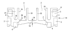
- a concave portion (space) 2 partitioned by a frame portion 1F, a weighting rib 1A, and a second rib 1B is formed on the side opposite to the processing surface portion 1W including the processing surface, and a plurality of segments are used.
- a third rib 1C is formed on the lower mold (see FIG. 3).
- FIG. 14A Regular grid mold 14A having regular grid ribs 1B in plan view shown in FIG. (2)
- a slanted lattice mold 14B having slanted lattice ribs 1B in plan view shown in FIG. (3)
- a honeycomb-shaped mold 14C having ribs 1B in a honeycomb shape in a perspective view shown in FIG. (4)
- a truss-shaped mold 14D having truss-shaped ribs 1B in plan view shown in FIG. (5)
- a circular mold 14E having ribs 1B having circular recesses in plan view shown in FIG.
- the mold has a frame portion 1F, a processing surface portion 1W, and ribs intersecting the processing surface portion 1W, and a concave portion (space) 2 surrounded by the ribs,
- a plurality of segments are formed by a combination of ribs and frame portions 1F and concave portions (spaces) 2 surrounded by them.
- the frame portion 1F, the processed surface portion 1W, and the processed surface portion 1W are formed continuously and integrally.
- the ribs partition adjacent recesses (spaces) 2, and the number of segments corresponding to the number of recesses (spaces) 2 is formed.
- Segments take various forms. 1 and 3, a weighting rib 1A continuously extending in a first direction (the X direction in FIG. 1) in plan view, and a plurality of second ribs 1B intersecting with the weighting rib 1A. There is a segment having a concave portion (space) 2 together with the frame portion 1F. In addition, there is a segment having a concave portion (space) 2 formed by the weighting rib 1A and the plurality of second ribs 1B. Furthermore, the second ribs 1B may not intersect the weighting ribs 1A, and the combination of a plurality of the second ribs 1B may constitute a segment having a recess (space) 2. FIG.
- the weighting rib 1A extends in the first direction (X direction in FIG. 1).
- extending in the first direction means that in addition to extending in a straight line, it may extend in the first direction (the X direction in FIG. 1) as a whole, even though it has a curved shape or steps. This also means that aligned ones are included.
- Such weighting ribs 1A are provided, for example, in order to partially (weight) increase the rigidity of a honeycomb mold 14C forming a honeycomb by only the second ribs 1B, as shown in FIG. to form.
- the significance of the weighting rib 1A is not only that it is “along the first direction", but also that it "forms a predetermined shape (for example, forms a honeycomb shape) in order to partially increase the rigidity. It is a rib that satisfies both conditions that the rib is formed by weighting. Therefore, for example, in the example of the regular lattice mold 14A shown in FIG. 4, the condition that the ribs are "along the first direction" is satisfied, but the latter condition that the ribs are "formed in a weighted manner" is fulfilled. Since it does not meet the conditions, it is not called the weighted rib 1A.
- This honeycomb mold 14C1 has many segments on the back side. That is, a weighting rib 1A extending in a first direction (the X direction in FIG. 1), a plurality of second ribs 1B intersecting with the weighting rib 1A, and a frame portion 1F have segments having recesses (spaces) 2. As shown in FIG. It also has a segment that does not intersect with the frame portion 1F and forms a concave portion (space) 2 with the weighting rib 1A and the plurality of second ribs 1B. Further, the second ribs 1B may not intersect with the frame portion 1F and the weighting ribs 1A, and the combination of a plurality of the second ribs 1B may constitute a segment having the concave portion (space) 2 .
- FIGS. 2 and 3 show an example of bending and press-molding the automobile metal plate 12 (see FIG. 11) with the upper mold 14 and the lower mold 13.
- FIG. 11 shows an example of bending and press-molding the automobile metal plate 12 (see FIG. 11) with the upper mold 14 and the lower mold 13.
- the outer peripheral surface of the frame portion 1F of the upper mold 14 circulates around the entire circumference including the frame portion 1F.
- Intermediate ribs 4 are formed (on the front and rear surfaces and on the left and right surfaces) (illustration of the intermediate ribs 4 is omitted in FIG. 1). According to this aspect, the outward collapse deformation of the frame portion due to the outward horizontal load acting on the mold due to the compressive load during molding can be suitably suppressed in the extending direction of the intermediate ribs. Further, the formation of the intermediate ribs 4 can ensure the rigidity, and the formation of the side recesses 5 can reduce the weight.
- the recess (space) 2 is also formed in the lower mold 15 .
- high-strength upper die inserts (blocks) 6 made of a material different from that of the upper die 14 are provided on both sides of the machined surface portion 1W of the upper die 14 .
- Blank holder inserts (blocks) 15 made of a material different from that of the lower mold 13 are provided on both sides of the machined surface portion 1W of the lower mold 13 .
- a bent portion (curved portion) Z is provided between the shoulder portion of the machined surface portion 1W of the lower die 13 and the upper die insert (block) 6 .
- a blank holder insert (block) 15 of the lower mold 13 is held by a blank holder 16 .
- the lower side of the lower die 13 is closed by the lower die punch holder 17 connected by bolts (not shown) or the like, but the recess (space) 2 can be opened.
- the upper side of the upper mold 14 can be closed by a lower punch holder (not shown).
- a weighting rib 1A is formed along the first direction (X direction) at a position corresponding to the bent portion (curved portion) Z. As shown in FIG.
- a third rib 1C is formed on the lower die 13 corresponding to the weighting rib 1A.
- the weighting rib 1A and the third rib 1C are not required to be completely aligned with the bent portion (curved portion) Z in the horizontal direction. may be
- the corner along the first direction where the frame portion 1F and the processed surface portion 1W are continuous is arcuate with the center of curvature inside the recess 2.
- a corner portion along the first direction where the central side of the first rib 1A and the second rib 1B are connected to the processed surface portion 1W is an arc-shaped portion 3B having a center of curvature inside the recess 2. ing. If the bottom corner is, for example, 90 degrees, that portion may be damaged when a press load acts. It has the advantage of preventing
- the arc-shaped portions 3A and 3B may be arc-shaped, or arc-shaped by connecting and combining those having different curvature radii.
- the curvature of the arcuate portion 3A is larger than the curvature of the arcuate portion 3B.
- the radius of curvature of the arcuate portion 3A and the arcuate portion 3B is preferably 20-70 mm.
- the wall thickness tf of the frame portion 1F is 40-60 mm
- the wall thickness ta of the first rib 1A, and the wall thickness tb of the second rib 1B is 20-40 mm.
- the segment rib spacing L is preferably 170 to 230 mm, particularly 180 to 220 mm.
- the inventors mainly studied the rigidity of molds having rib shapes and concave shapes shown in molds 14A to 14G shown in FIGS.
- the simulation was carried out under the conditions that the Young's modulus was selected within the range of 100 to 170 Ga and the shape of the upper die was simply a rectangular parallelepiped.
- As a "longitudinal load” the four corners of the bottom are constrained in the X direction and the Y direction, and the bottom side is constrained in the Z direction
- As a "lateral load” both sides in the Y direction (left and right sides) are constrained in the Y direction, and the bottom side is constrained in the Z direction.
- the volume (area in plan view) of the simulation sample is substantially the same, and the area of one recess, as shown in the drawing, is the section length L, and the length between opposing sides, the diameter, and the length between corners are changed. Then, we simulated the maximum displacement and the average displacement in the deformation due to "longitudinal load” and "lateral load".
- the results are shown in FIG.
- the vertical axis is the evaluation value, and the higher the evaluation value, the higher the rigidity.
- the results of FIG. 12 reveal the following.
- (1) The honeycomb shape has the highest rigidity against vertical load.
- (2) The oblique lattice shape and the longitudinal oblique lattice shape also have high rigidity against vertical loads.
- (3) Rigidity against lateral load is high in oblique lattice, truss, and longitudinal oblique lattice shapes.
- the honeycomb shape has remarkably high rigidity against vertical load, but the lateral load is at the same level as that of the grid shape. There is a similar tendency for circular ones.
- Shapes with oblique ribs that is, grid shapes, truss shapes, and vertically oblique lattice shapes, exhibit well-balanced rigidity with respect to both vertical and lateral loads.
- the horizontally oblique grid is not highly balanced with respect to both vertical and horizontal loads.
- the rib shape can be adjusted by selecting the load direction that requires the necessary rigidity for vertical load and lateral load according to the type of target metal material, molding shape, etc. can be selected. For example, if it is necessary to exhibit well-balanced rigidity with respect to both longitudinal and lateral loads, a diagonal lattice type, truss type, or oblong oblique lattice type can be selected. On the other hand, from the viewpoint of emphasizing the vertical load, it is possible to select a honeycomb shape, and in some cases a circular shape.
- the rib shape is the same as a whole (except for the example in which the weighting rib 1A of FIG. 1 is formed). However, for example, it is also possible to use a combination of ribs having different shapes.
- the examples shown in FIGS. 13 to 16 can be given.
- the formation region 10P of the honeycomb-shaped ribs 1 is formed in the central portion, and the rib formation regions 10Q of other shapes are formed in the peripheral portion.
- the example of FIG. 13 is a first example in which the shape of the peripheral portion is a truss shape.
- the example of FIG. 14 is a second example in which the shape of the peripheral portion is an oblique lattice shape.
- the example of FIG. 15 is a third example in which the shape of the peripheral portion is circular.
- the example of FIG. 16 is a fourth example in which the shape of the peripheral portion is a regular lattice shape.
- the first weighting rib 1A shown in FIG. 1 is formed along the first direction (X direction) in order to partially increase the rigidity. Similar first ribs 1Ay can be formed in order to partially increase the rigidity in the second direction (Y direction) as well. It should be noted that the first rib 1A and/or the first rib 1Ay may intersect the frame portion 1F, as indicated by the phantom lines in FIG. Furthermore, although the weighting ribs 1A shown in FIG. 1 are longitudinally aligned, they may be laterally aligned.
- the weighting ribs 1Ay shown in the figures can be said to be formed in order to partially increase the rigidity when paying attention to the honeycomb-shaped ribs.
- the compressive load during molding acts on the mold.
- the deformation of the frame due to an outward horizontal load in the case of the upper mold, it bends downward and warps and deforms so that the frame opens) can be preferably prevented by forming the intermediate ribs. can be suppressed.
- the intermediate rib 4 acts to increase the weight of the mold, but the formation of the side concave portions 5, 5 on the upper and lower sides of the intermediate rib 4 acts to reduce the weight of the mold. It is possible to increase rigidity while suppressing an increase in mold weight.
- the intermediate rib 4 surrounds the corner portion 14X of the mold and surrounds the entire circumference including the front and rear surfaces and the left and right surfaces of the frame portion 1F.
- the side concave portions 5, 5 are formed at least on the front and rear surfaces and the left and right surfaces of the frame portion 1F except for the corner portion 14X. Since the corner portion of the mold is a portion that ensures rigidity against the press load as a column, the formation of side recesses that result in a reduction in the thickness of the frame portion should be suppressed as much as possible.
- the present inventor conducted simulations on various forms, using as a basic example only the vertical ribs 14V formed on the frame portion 14F.
- the top surface S of FIG. 18 is a configuration of segments in the form of FIG.
- a first example is an example in which the thickness tf of the frame portion 1F is changed from 40 mm to 50 mm.
- a second example is an example in which the thickness 1w of the processed surface portion is changed from 40 mm to 50 mm.
- an intermediate rib is formed around the corner portion 14X of the mold and around the entire circumference including the front and rear surfaces and the left and right surfaces of the frame portion 1F.
- forming the intermediate rib can suppress the deformation OP and deformation BP of the formwork, although the weight is slightly increased.
- the height of the intermediate rib 4 is shown to be the same on the front, rear, left, and right surfaces, but the inventors have It has been confirmed that the effects shown in Table 1 can be obtained, for example.
- the present invention can be applied not only to presses for cold working, but also to molds in press machines for hot stamping1.
Landscapes
- Engineering & Computer Science (AREA)
- Mechanical Engineering (AREA)
- Chemical & Material Sciences (AREA)
- Materials Engineering (AREA)
- Shaping Metal By Deep-Drawing, Or The Like (AREA)
- Mounting, Exchange, And Manufacturing Of Dies (AREA)
- Moulds For Moulding Plastics Or The Like (AREA)
- Press-Shaping Or Shaping Using Conveyers (AREA)
Abstract
Description
上金型にはプレス加工性の観点から高い剛性が求められるために、従来は、加工面のみならず、背面に至る全体が無垢のブロック状のものであった(例えば、特許文献1)。 The press molding machine has a fixed lower mold and an upper mold that moves up and down by the press.
Since the upper mold is required to have high rigidity from the viewpoint of press workability, conventionally, not only the processed surface but also the entire back surface has been a solid block shape (for example, Patent Document 1).
高さ方向下方に設けられた下金型と、上方に設けられた上金型と、この上金型を上下動させるプレス機構とを備えるプレス機に使用する金型において、
前記金型は、枠部と、加工面部と、前記加工面部と交差するリブとを有し、
前記リブ、あるいは前記リブ及び前記枠部と、これによって囲まれた空間との組み合わせによるセグメントが複数形成されている、
ことを特徴とするプレス用金型。 A press die that solves the above problems has the following features.
A mold used in a press machine comprising a lower mold provided below in the height direction, an upper mold provided above, and a press mechanism for moving the upper mold up and down,
The mold has a frame portion, a processing surface portion, and ribs intersecting the processing surface portion,
A plurality of segments are formed by a combination of the rib, or the rib and the frame, and the space surrounded by the rib,
A press die characterized by:
さらに、形成したセグメントの空間により軽量化を図ることができる。
要すれば、複数のセグメントと枠部とにより。軽量でありながら十分な剛性を有する金型を提供することができる。 According to this aspect, the vertical forming load applied to the processing surface is supported by a plurality of segments formed by a combination of the ribs or the ribs and the frame and the space surrounded by the ribs, and the compressive load during forming is applied. An outward horizontal load acting on the mold can be supported by the frame.
Furthermore, weight reduction can be achieved by the space of the formed segment.
With a plurality of segments and a frame, if desired. It is possible to provide a mold that is lightweight yet has sufficient rigidity.
第1のリブは、複数の第2のリブを交差して第1の方向に延びるものであるから、第1の方向における曲げに対する剛性は高いものである。 A mode is proposed in which the segment has a first rib extending in a first direction in plan view and a plurality of second ribs intersecting with the first rib.
Since the first ribs intersect the plurality of second ribs and extend in the first direction, the rigidity against bending in the first direction is high.
これに対して、倒れ変形を重視する必要のない、リブと加工面部とが連なる方向に沿う角部の弧状部の曲率は、前記枠部側の弧状部の曲率より相対的に小さくすることにより、その分、空間の容積を大きくすることになり、軽量化に寄与する。 By increasing the curvature of the arc-shaped portion of the corner along the direction in which the frame and the machined surface are connected, the outward collapse deformation of the frame due to the outward horizontal load acting on the mold due to the compressive load during molding is suppressed. It can be suitably suppressed.
On the other hand, the curvature of the arc-shaped portion of the corner along the direction in which the rib and the processed surface portion are continuous, which does not require emphasis on collapse deformation, is made relatively smaller than the curvature of the arc-shaped portion on the frame side. , the volume of the space will be increased accordingly, contributing to weight reduction.
プレス成型装置11の構成を説明するうえで、方向を示すにあたっては、便宜上、紙面の手前側を前側とし、紙面の裏側を後側として説明する。また、図11に示すプレス成型装置11を前側から見た状態で上側をプレス成型装置11の上側、左右をプレス成型装置11の左右として説明する。
金型についても同様であり、図1が参照されるように、前後をX方向、左右をY方向、高さ方向をZ方向ともいう。また、X方向及びY方向の一方を第1の方向という場合、他方が第2の方向である。 A
In describing the configuration of the
The same applies to the mold, and as shown in FIG. 1, the front and back are also referred to as the X direction, the left and right as the Y direction, and the height direction as the Z direction. Further, when one of the X direction and the Y direction is called the first direction, the other is the second direction.
これによって、軽量化を図ることができるとともに、十分な剛性を有する金型を提供することができる。また、特に上金型については、軽量化に伴って、プレス機の上下動機構などにかかる負担が小さくなり、高速での高精度での成型が可能となる。 In the following embodiment, as a mold, a concave portion (space) 2 partitioned by a
As a result, it is possible to reduce the weight and provide a mold having sufficient rigidity. In particular, with respect to the upper mold, as the weight is reduced, the burden on the vertical movement mechanism of the press machine and the like is reduced, and molding can be performed at high speed and with high accuracy.
(1)図4に示す平面視で正格子状のリブ1Bを有する正格子形金型14A
(2)図5に示す平面視で斜格子状のリブ1Bを有する斜格子形金型14B
(3)図6に示す斜視視でハニカム状のリブ1Bを有するハニカム形金型14C
(4)図7に示す平面視でトラス状のリブ1Bを有するトラス形金型14D
(5)図8に示す平面視で円形凹部を有するリブ1Bを有する円形金型14E
(6)図9に示す平面視で縦長(前後に長い)斜格子状のリブ1Bを有する縦長斜格子形金型14F
(7)図10に示す平面視で縦長(前後に長い)斜格子状のリブ1Bを有する横長斜格子形金型14G Various types of molds can be used as the (upper) mold. Examples include:
(1)
(2) A slanted
(3) A honeycomb-shaped
(4) A truss-shaped
(5) A
(6) Longitudinally oblong lattice-shaped
(7) Horizontal
前記枠部1Fと、前記加工面部1Wと、前記加工面部1Wとが連続して一体として形成されている。
リブは隣接する凹部(空間)2を仕切っており、凹部(空間)2の数だけセグメントが形成されている。 For example, as shown in FIG. 1, the mold has a
The
The ribs partition adjacent recesses (spaces) 2, and the number of segments corresponding to the number of recesses (spaces) 2 is formed.
また、加重リブ1Aと複数の第2のリブ1Bとで凹部(空間)2を有するセグメントを構成するものがある。
さらに、第2のリブ1Bは、加重リブ1Aと交差しないで、複数の第2のリブ1Bの組み合わせで凹部(空間)2を有するセグメントを構成するものもある。 Segments take various forms. 1 and 3, a
In addition, there is a segment having a concave portion (space) 2 formed by the
Furthermore, the
したがって、例えば図4に示す正格子形金型14Aの例では、リブが「第1の方向に沿っている」ことの条件を満たすが、後者の「加重的にリブが形成された」ことの条件を満たしていないので、加重リブ1Aとは称しない。 The significance of the
Therefore, for example, in the example of the
すなわち、第1の方向(図1のX方向)に延びる加重リブ1Aと、これと交差する複数の第2のリブ1Bと枠部1Fとで、凹部(空間)2を有するセグメントを有する。
また、枠部1Fと交差しないで、加重リブ1Aと複数の第2のリブ1Bとで凹部(空間)2を形成するセグメントをも有する。
さらに、第2のリブ1Bは、枠部1F及び加重リブ1Aと交差しないで、複数の第2のリブ1Bの組み合わせで凹部(空間)2を有するセグメントを構成するものもある。 A honeycomb mold 14C1, which is a typical example of the upper mold, is shown in FIGS. This honeycomb mold 14C1 has many segments on the back side.
That is, a
It also has a segment that does not intersect with the
Further, the
この態様によると、成型時の圧縮荷重により金型に作用する外向きの水平荷重による枠部の外向きの倒れ変形を、中間リブの延在方向について、好適に抑制できる。また、中間リブ4の形成によって剛性が担保できるとともに、側面凹部5の形成によって軽量化を図ることができる。 As shown in FIGS. 3, 20, and 21, around the
According to this aspect, the outward collapse deformation of the frame portion due to the outward horizontal load acting on the mold due to the compressive load during molding can be suitably suppressed in the extending direction of the intermediate ribs. Further, the formation of the
下金型13の加工面部1Wの両側部には、下金型13と別材質のブランクホルダインサート(ブロック)15が設けられている。
下金型13の加工面部1Wの肩部と上型ダイインサート(ブロック)6との間は、曲げ加工部(曲部)Zとなっている。 As shown in FIG. 3 , high-strength upper die inserts (blocks) 6 made of a material different from that of the
Blank holder inserts (blocks) 15 made of a material different from that of the
A bent portion (curved portion) Z is provided between the shoulder portion of the machined
なお、図示例においては、下金型13の下側は、ボルト(図示せず)などによって連結された下型パンチホルダ17によって閉じられているが、凹部(空間)2の開放も可能である。
また、同様に、上金型14の上側を下型パンチホルダ(図示せず)によって閉じることも可能である。 A blank holder insert (block) 15 of the
In the illustrated example, the lower side of the
Similarly, the upper side of the
加重リブ1A及び第3のリブ1Cは、曲げ加工部(曲部)Zと水平方向の位置が完全に一致することを要求されるものではなく、水平方向に50mm程度まで範囲内で偏位されていてもよい。 Further, a
The
仮に、底角部が例えば90度であると、プレス荷重が作用したとき、その部分が損傷する可能性があるのに対して、弧状部であると、荷重が分散し応力集中がなく、損傷を防止できるなどの利点をもたらす。
弧状部3A、3Bは円弧状のほか、曲率半径が相違するものをつないで組み合わせた弧状のものでもよい。
ここで、弧状部3Aの曲率は、弧状部3Bの曲率より大きいのが望ましい。弧状部3A及び弧状部3Bの曲率半径は20~70mmが望ましい。 On the other hand, as shown in FIG. 3, focusing on the bottom corner portion of the
If the bottom corner is, for example, 90 degrees, that portion may be damaged when a press load acts. It has the advantage of preventing
The arc-shaped
Here, it is desirable that the curvature of the
シミュレーションに際し、ヤング率が100~170Gaの範囲内の設定値を選択し、かつ、上金型の形状を単純に直方体とした条件で行った。
「縦荷重」として、底面の4隅をX方向及びY方向に拘束し、かつ、底面側をZ方向に拘束する、
「横荷重」として、Y方向の両側面(左右側面)をY方向に拘束し、かつ、底面側をZ方向に拘束する、
条件下で、「縦荷重」及び「横荷重」に伴う変形量を算出した。 The inventors mainly studied the rigidity of molds having rib shapes and concave shapes shown in
The simulation was carried out under the conditions that the Young's modulus was selected within the range of 100 to 170 Ga and the shape of the upper die was simply a rectangular parallelepiped.
As a "longitudinal load", the four corners of the bottom are constrained in the X direction and the Y direction, and the bottom side is constrained in the Z direction,
As a "lateral load", both sides in the Y direction (left and right sides) are constrained in the Y direction, and the bottom side is constrained in the Z direction,
Under these conditions, the amount of deformation due to "longitudinal load" and "lateral load" was calculated.
図12の結果から次のことが判る。
(1)縦荷重に対する剛性は、ハニカム形状が最も高い。
(2)斜格子形及び縦長斜格子形のものについても、縦荷重に対する剛性が高い。
(3)横荷重に対する剛性は、斜格子形、トラス形、縦長斜格子形のものが高い。
(4)他方で、ハニカム形状のものは、縦荷重に対する剛性は顕著に高いものの、横荷重については、格子状のものと同レベルである。
円形のものについても、同様の傾向がある。
(5)斜めにリブが通る形状のもの、すなわち格子形、トラス形、縦長斜格子形のものは、縦荷重及び横荷重の両者について、バランスのよい剛性を示す。
(6)横長斜格子のものは、縦荷重及び横荷重の両者について、バランスが高くない。 The results are shown in FIG. The vertical axis is the evaluation value, and the higher the evaluation value, the higher the rigidity.
The results of FIG. 12 reveal the following.
(1) The honeycomb shape has the highest rigidity against vertical load.
(2) The oblique lattice shape and the longitudinal oblique lattice shape also have high rigidity against vertical loads.
(3) Rigidity against lateral load is high in oblique lattice, truss, and longitudinal oblique lattice shapes.
(4) On the other hand, the honeycomb shape has remarkably high rigidity against vertical load, but the lateral load is at the same level as that of the grid shape.
There is a similar tendency for circular ones.
(5) Shapes with oblique ribs, that is, grid shapes, truss shapes, and vertically oblique lattice shapes, exhibit well-balanced rigidity with respect to both vertical and lateral loads.
(6) The horizontally oblique grid is not highly balanced with respect to both vertical and horizontal loads.
例えば、縦荷重及び横荷重の両者について、バランスのよい剛性を示すことが必要であれば、斜格子形、トラス形、縦長斜格子形のものを選定できる。
他方で、縦荷重を重視する観点からは、特にハニカム形状のもの、場合により円形ものを選定できる。 As shown in the above results, the rib shape can be adjusted by selecting the load direction that requires the necessary rigidity for vertical load and lateral load according to the type of target metal material, molding shape, etc. can be selected.
For example, if it is necessary to exhibit well-balanced rigidity with respect to both longitudinal and lateral loads, a diagonal lattice type, truss type, or oblong oblique lattice type can be selected.
On the other hand, from the viewpoint of emphasizing the vertical load, it is possible to select a honeycomb shape, and in some cases a circular shape.
しかるに、例えばリブ形状が異なるものを組み合せて使用することもできる。 On the other hand, in each of the above examples, the rib shape is the same as a whole (except for the example in which the
However, for example, it is also possible to use a combination of ribs having different shapes.
このリブ形状が異なるものを組み合せて使用することは、上記のシミュレーションによって得た、それぞれのリブ形状の利点を利用しながら、対象とする材料のプレス形態に好適に適応した金型を得ることができるようになる。 Specifically, the example of FIG. 13 is a first example in which the shape of the peripheral portion is a truss shape. The example of FIG. 14 is a second example in which the shape of the peripheral portion is an oblique lattice shape. The example of FIG. 15 is a third example in which the shape of the peripheral portion is circular. The example of FIG. 16 is a fourth example in which the shape of the peripheral portion is a regular lattice shape.
Using a combination of ribs with different shapes makes it possible to obtain a mold suitable for the press form of the target material while utilizing the advantages of each rib shape obtained by the above simulation. become able to.
なお、図17に仮想線で示すように、第1のリブ1A及び又は第1のリブ1Ayを枠部1Fと交差するようにしてもよい。
さらに、図1に示された加重リブ1Aは長手方向に沿っているが、短手方向に沿っていてもよい。 By the way, the
It should be noted that the
Furthermore, although the
金型では、成型時の圧縮荷重により金型に作用する外向きの水平荷重による枠部の外向きの開き変形が生じる。上金型の場合には、図18に示すように、横断面上で下向きに湾曲して反り返る変形OPが生じ、縦断面では、前後端が固定されているために、上向きに湾曲して反り返る圧縮変形BPが生じる傾向がある。 Next, the advantage of forming the
In the mold, an outward opening deformation of the frame portion occurs due to an outward horizontal load acting on the mold due to a compressive load during molding. In the case of the upper die, as shown in FIG. 18, a deformation OP in which the cross section is curved downward and warped occurs, and the longitudinal section is curved upward and warped because the front and rear ends are fixed. Compression deformation BP tends to occur.
第2例は、加工面部の厚み1wを40mmから50mmに変更した例である。
第3例は、図20に示すように、金型のコーナー部14Xを巡って、枠部1Fの前後面及び左右面を含む全周に周回して中間リブを形成したものである。 A first example is an example in which the thickness tf of the
A second example is an example in which the thickness 1w of the processed surface portion is changed from 40 mm to 50 mm.
In the third example, as shown in FIG. 20, an intermediate rib is formed around the

Claims (10)
- 高さ方向下方に設けられた下金型と、上方に設けられた上金型と、この上金型を上下動させるプレス機構とを備える自動車車体用のハイテン金属板のプレス機に使用する金型において、
前記金型は、枠部と、加工面部と、前記加工面部と交差するリブとを有し、
前記リブによって囲まれた空間、あるいは前記リブ及び前記枠部によって囲まれた空間との組み合わせによるセグメントが複数形成されており、
前記枠部の外周囲面を構成する枠部の前後面及び左右面を周回して中間リブが形成されており、
前記中間リブは上下それぞれに側面凹部を形成するものであり、
前記枠部、前記加工面部および前記リブが連続して一体として形成されている、
ことを特徴とするプレス用金型。 A metal used in a press machine for high-tensile steel plates for automobile bodies, equipped with a lower die provided below in the height direction, an upper die provided above, and a press mechanism for moving the upper die up and down. In the type
The mold has a frame portion, a processing surface portion, and ribs intersecting the processing surface portion,
A plurality of segments are formed by combining the space surrounded by the ribs or the space surrounded by the ribs and the frame,
An intermediate rib is formed around the front and rear surfaces and the left and right surfaces of the frame that constitutes the outer peripheral surface of the frame,
The intermediate ribs form side concave portions on the upper and lower sides, respectively,
wherein the frame portion, the machined surface portion and the rib are continuously formed as one body,
A press die characterized by: - 前記セグメントは、平面視で第1の方向に延びる第1のリブと、この第1のリブと交差する複数の第2のリブとを有し、
前記第1のリブが延びる第1の方向と、加工面部の曲部の稜線方向とが一致している、請求項1に記載のプレス用金型。 The segment has a first rib extending in a first direction in plan view and a plurality of second ribs intersecting the first rib,
2. The press die according to claim 1, wherein the first direction in which said first rib extends coincides with the ridge line direction of the curved portion of the machined surface portion. - 前記セグメントは、平面視で第1の方向に延びる第1のリブと、この第1のリブと交差する複数の第2のリブとを有し、
前記第1のリブは、前記加工面部の曲部に沿っており、
前記枠部と加工面部との連なる第1の方向に沿う角部が弧状部となった枠部側の曲率半径は、前記リブと加工面部との連なる前記第1の方向に沿う角部が弧状部となったリブ側の曲率半径より大きい請求項1に記載のプレス用金型。 The segment has a first rib extending in a first direction in plan view and a plurality of second ribs intersecting the first rib,
The first rib is along the curved portion of the processed surface portion,
The radius of curvature of the frame portion side, in which the corner portion along the first direction where the frame portion and the processed surface portion are connected is an arcuate portion, is such that the corner portion along the first direction where the rib and the processed surface portion are connected is arcuate. 2. The press die according to claim 1, wherein the radius of curvature of the portioned rib is larger than that of the rib. - 前記中間リブは、金型のコーナー部を巡って、前記枠部の前後面及び左右面を含む全周に周回しており、少なくとも前記コーナー部を除く前記枠部の前後面及び左右面において、前記側面凹部が形成されている請求項1~3のいずれか1項に記載のプレス用金型。 The intermediate rib encircles the entire periphery including the front and rear surfaces and the left and right surfaces of the frame around the corners of the mold, and at least on the front and rear surfaces and the left and right surfaces of the frame except for the corners, The press die according to any one of claims 1 to 3, wherein the side concave portion is formed.
- 平面視で金型の中央部において、ハニカム形状を示す少なくとも一つのセグメントが形成されており、平面視で金型の周辺部においてハニカム形状とは異なるセグメントが形成されている請求項1に記載のプレス用金型。 2. The method according to claim 1, wherein at least one segment exhibiting a honeycomb shape is formed in the central portion of the mold in plan view, and a segment different from the honeycomb shape is formed in the peripheral portion of the mold in plan view. Mold for press.
- 前記セグメントは、平面視で第1の方向に延びる第1のリブと、この第1のリブと交差する複数の第2のリブとを有して、
前記第1のリブは、前記加工面部の曲部に沿っており、
前記第1のリブに対応して、他方の金型に第3のリブが形成されている請求項1記載のプレス用金型。 The segment has a first rib extending in a first direction in plan view and a plurality of second ribs intersecting the first rib,
The first rib is along the curved portion of the processed surface portion,
2. The press die according to claim 1, wherein a third rib is formed on the other die corresponding to said first rib. - 前記セグメントの少なくとも一つが平面視でハニカム形状を示している請求項1記載のプレス用金型。 The press die according to claim 1, wherein at least one of said segments exhibits a honeycomb shape in plan view.
- 前記セグメントは、平面視で第1の方向に延びる第1のリブと、この第1のリブと交差する複数の第2のリブとを有して、
前記第1のリブは、前記加工面部の曲部に沿っており、
前記曲部は、本体と材質が相違する別体のブロックにより形成されている請求項1記載のプレス用金型。 The segment has a first rib extending in a first direction in plan view and a plurality of second ribs intersecting the first rib,
The first rib is along the curved portion of the processed surface portion,
2. The press die according to claim 1, wherein the curved portion is formed of a separate block made of a material different from that of the main body. - 前記セグメントは、平面視で第1の方向に延びる第1のリブ、及び前記第1のリブと交差する複数の第2のリブを有し、
さらに、加重リブを有し、
前記加重のリブは、平面視で前記加工面部の曲部の稜線に沿っており、かつ、前記セグメントを形成する前記第1のリブ及び前記第2のリブに対して、加重的に形成されているリブである請求書1記載のプレス用金型。 The segment has a first rib extending in a first direction in plan view and a plurality of second ribs intersecting the first rib,
In addition, it has weighted ribs,
The weighting rib is along the ridge line of the curved portion of the machined surface portion in a plan view, and is formed to weight the first rib and the second rib forming the segment. The press die according to Claim 1, which is a rib that - 前記第1のリブ及び前記第2のリブによって形成されるセグメントの少なくとも一つが平面視でハニカム形状を示している請求項9記載のプレス用金型。 The press die according to claim 9, wherein at least one of the segments formed by the first ribs and the second ribs has a honeycomb shape in plan view.
Priority Applications (3)
| Application Number | Priority Date | Filing Date | Title |
|---|---|---|---|
| CN202280048663.3A CN117615864A (en) | 2021-07-16 | 2022-07-15 | Stamping die |
| CA3224239A CA3224239A1 (en) | 2021-07-16 | 2022-07-15 | Mold for press |
| US18/574,364 US20240293860A1 (en) | 2021-07-16 | 2022-07-15 | Pressing die |
Applications Claiming Priority (2)
| Application Number | Priority Date | Filing Date | Title |
|---|---|---|---|
| JP2021118253A JP7297014B2 (en) | 2021-07-16 | 2021-07-16 | Press mold |
| JP2021-118253 | 2021-07-16 |
Publications (1)
| Publication Number | Publication Date |
|---|---|
| WO2023286867A1 true WO2023286867A1 (en) | 2023-01-19 |
Family
ID=84920351
Family Applications (1)
| Application Number | Title | Priority Date | Filing Date |
|---|---|---|---|
| PCT/JP2022/027929 WO2023286867A1 (en) | 2021-07-16 | 2022-07-15 | Mold for press |
Country Status (5)
| Country | Link |
|---|---|
| US (1) | US20240293860A1 (en) |
| JP (2) | JP7297014B2 (en) |
| CN (1) | CN117615864A (en) |
| CA (1) | CA3224239A1 (en) |
| WO (1) | WO2023286867A1 (en) |
Citations (5)
| Publication number | Priority date | Publication date | Assignee | Title |
|---|---|---|---|---|
| JPH067865A (en) * | 1992-05-14 | 1994-01-18 | Sumitomo Light Metal Ind Ltd | Manufacture of brazed sandwich panel and jig for manufacturing |
| JP2002224764A (en) * | 2001-02-07 | 2002-08-13 | Kota Noda | Die set in which lightweight of driving block is achieved |
| JP2011235305A (en) * | 2010-05-10 | 2011-11-24 | Honda Motor Co Ltd | Cooling device, and cooling method of drawing die |
| JP2014533608A (en) * | 2011-11-23 | 2014-12-15 | ティッセンクルップ スチール ヨーロッパ アクチェンゲゼルシャフトThyssenKrupp Steel Europe AG | Method and forming tool for hot forming and press-hardening a thin steel plate workpiece, particularly a galvanized thin steel plate workpiece |
| JP2015507581A (en) * | 2011-12-27 | 2015-03-12 | ブラジレイタ エス/エイ エンバラゲンス メタリカスBrasilata S/A Embalagens Metalicas | Can with polygonal cross section |
Family Cites Families (16)
| Publication number | Priority date | Publication date | Assignee | Title |
|---|---|---|---|---|
| JPS4938700B1 (en) * | 1969-04-08 | 1974-10-19 | ||
| JPS5917467Y2 (en) * | 1981-07-10 | 1984-05-22 | トヨタ自動車株式会社 | casting mold |
| JPS59171611A (en) * | 1983-03-18 | 1984-09-28 | Showa Aircraft Ind Co Ltd | Mold for thermosetting resin product |
| JPH049226A (en) * | 1989-12-15 | 1992-01-14 | Taiho Seiki Kk | Press die assembly |
| JP3010925B2 (en) * | 1992-09-18 | 2000-02-21 | 株式会社日立製作所 | Brazed laminated panel and method of manufacturing the same |
| JPH06285547A (en) * | 1993-04-02 | 1994-10-11 | Itoki Crebio Corp | Die for working sheet metal |
| JP2834050B2 (en) * | 1995-10-05 | 1998-12-09 | 株式会社神戸製鋼所 | Brazed honeycomb panel |
| JPH11291339A (en) * | 1998-04-10 | 1999-10-26 | Purosupii:Kk | Curved panel forming apparatus |
| JP3444788B2 (en) | 1998-07-09 | 2003-09-08 | 住友軽金属工業株式会社 | Honeycomb panel |
| JP2000334313A (en) | 1999-06-01 | 2000-12-05 | Yutaka Giken Co Ltd | Metal catalyst carrier |
| JP2001150046A (en) * | 1999-11-22 | 2001-06-05 | Honda Motor Co Ltd | Reinforced construction of superplastic forming mold |
| JP4517840B2 (en) * | 2004-12-06 | 2010-08-04 | トヨタ自動車株式会社 | Press forming equipment |
| JP4617262B2 (en) * | 2006-01-16 | 2011-01-19 | 株式会社オギハラ | Press mold equipment |
| JP4640265B2 (en) * | 2006-06-02 | 2011-03-02 | トヨタ自動車株式会社 | Press forming equipment |
| US20110291995A1 (en) * | 2010-05-25 | 2011-12-01 | Industrial Technology Research Institute | Sterilizing device and manufacturing method for sterilizing device |
| CN210188133U (en) | 2019-06-24 | 2020-03-27 | 广西艾盛创制科技有限公司 | Bending die for hyperboloid aluminum alloy section |
-
2021
- 2021-07-16 JP JP2021118253A patent/JP7297014B2/en active Active
-
2022
- 2022-04-27 JP JP2022072994A patent/JP7432651B2/en active Active
- 2022-07-15 CA CA3224239A patent/CA3224239A1/en active Pending
- 2022-07-15 US US18/574,364 patent/US20240293860A1/en active Pending
- 2022-07-15 WO PCT/JP2022/027929 patent/WO2023286867A1/en active Application Filing
- 2022-07-15 CN CN202280048663.3A patent/CN117615864A/en active Pending
Patent Citations (5)
| Publication number | Priority date | Publication date | Assignee | Title |
|---|---|---|---|---|
| JPH067865A (en) * | 1992-05-14 | 1994-01-18 | Sumitomo Light Metal Ind Ltd | Manufacture of brazed sandwich panel and jig for manufacturing |
| JP2002224764A (en) * | 2001-02-07 | 2002-08-13 | Kota Noda | Die set in which lightweight of driving block is achieved |
| JP2011235305A (en) * | 2010-05-10 | 2011-11-24 | Honda Motor Co Ltd | Cooling device, and cooling method of drawing die |
| JP2014533608A (en) * | 2011-11-23 | 2014-12-15 | ティッセンクルップ スチール ヨーロッパ アクチェンゲゼルシャフトThyssenKrupp Steel Europe AG | Method and forming tool for hot forming and press-hardening a thin steel plate workpiece, particularly a galvanized thin steel plate workpiece |
| JP2015507581A (en) * | 2011-12-27 | 2015-03-12 | ブラジレイタ エス/エイ エンバラゲンス メタリカスBrasilata S/A Embalagens Metalicas | Can with polygonal cross section |
Also Published As
| Publication number | Publication date |
|---|---|
| JP7432651B2 (en) | 2024-02-16 |
| JP7297014B2 (en) | 2023-06-23 |
| JP2023013940A (en) | 2023-01-26 |
| JP2023013819A (en) | 2023-01-26 |
| CA3224239A1 (en) | 2023-01-19 |
| CN117615864A (en) | 2024-02-27 |
| US20240293860A1 (en) | 2024-09-05 |
Similar Documents
| Publication | Publication Date | Title |
|---|---|---|
| EP3437751B1 (en) | Method for manufacturing press-formed article | |
| CN105813773A (en) | Steel plate material, method for producing same and device for producing same, and method for producing press molded article using said steel plate material | |
| WO2015174353A1 (en) | Blank, and method for producing press-molded article | |
| WO2018030240A1 (en) | Method of manufacturing press-formed article | |
| JP6672933B2 (en) | Automotive structural member, manufacturing method thereof, and mold | |
| KR20200108069A (en) | Metal plate for press forming, press forming apparatus, and manufacturing method of press parts | |
| RU2706253C1 (en) | Extruded vehicle body component and method of its manufacturing | |
| US20240238861A1 (en) | Press-formed article | |
| WO2023286867A1 (en) | Mold for press | |
| JP2023013940A5 (en) | ||
| US12036596B2 (en) | Press forming method | |
| JP7323824B2 (en) | Method for manufacturing press-formed product and press-forming apparatus | |
| WO2021125293A1 (en) | Method for manufacturing press-formed product, press-forming device, and press-forming line | |
| JP7448464B2 (en) | Manufacturing method of steel parts | |
| JP7044208B2 (en) | Manufacturing method of press-molded products and press-molding line | |
| KR20210141654A (en) | Press forming method | |
| KR20210141652A (en) | Press forming method | |
| TWI554343B (en) | Press forming die and producing method of pressed products | |
| JP4105816B2 (en) | Hollow profile | |
| WO2021182528A1 (en) | Manufacturing method for hat-shaped steel piling | |
| JP7513917B2 (en) | Molds and press molding equipment | |
| WO2020090153A1 (en) | Press formed component and method for manufacturing same | |
| TWI555592B (en) | Press forming die and producing method of pressed products | |
| JP2012111377A (en) | Cross member for metal vehicle | |
| JP2000203360A (en) | Hollow extruded section |
Legal Events
| Date | Code | Title | Description |
|---|---|---|---|
| 121 | Ep: the epo has been informed by wipo that ep was designated in this application |
Ref document number: 22842208 Country of ref document: EP Kind code of ref document: A1 |
|
| WWE | Wipo information: entry into national phase |
Ref document number: 3224239 Country of ref document: CA |
|
| WWE | Wipo information: entry into national phase |
Ref document number: 202280048663.3 Country of ref document: CN |
|
| NENP | Non-entry into the national phase |
Ref country code: DE |
|
| 122 | Ep: pct application non-entry in european phase |
Ref document number: 22842208 Country of ref document: EP Kind code of ref document: A1 |