JP2012111377A - Cross member for metal vehicle - Google Patents
Cross member for metal vehicle Download PDFInfo
- Publication number
- JP2012111377A JP2012111377A JP2010262657A JP2010262657A JP2012111377A JP 2012111377 A JP2012111377 A JP 2012111377A JP 2010262657 A JP2010262657 A JP 2010262657A JP 2010262657 A JP2010262657 A JP 2010262657A JP 2012111377 A JP2012111377 A JP 2012111377A
- Authority
- JP
- Japan
- Prior art keywords
- web
- cross member
- bent
- longitudinal direction
- side walls
- Prior art date
- Legal status (The legal status is an assumption and is not a legal conclusion. Google has not performed a legal analysis and makes no representation as to the accuracy of the status listed.)
- Granted
Links
Images


Abstract
Description
この発明は、金属製車両用クロスメンバーに関するものである。 The present invention relates to a cross member for a metal vehicle.
従来、自動車の車体に使用されている金属製車両用クロスメンバー(以下、単にクロスメンバーという)は、図1に示す一対のサイドメンバー50を連結するように架設されている。近年はサイドメンバー50を低く配置することにより、自動車の低床化が図られている。そこで、車体の下部に位置するプロペラシャフト60や或いは燃料タンクの配置スペースSPを確保するために、中間部が鞍型に折り曲げされたクロスメンバーが使用されている。
2. Description of the Related Art Conventionally, a metal vehicle cross member (hereinafter simply referred to as a cross member) used in an automobile body is constructed so as to connect a pair of
鞍型に折り曲げされたクロスメンバーは、図12に示すように、ウエブ10、ウエブ10の両側縁から同じ方向に立設された一対の側壁12,14及び両側壁12,14の先端に張出し形成されたフランジ部16,18により構成されている。上記クロスメンバーは金属材料をプレス成形により、横断面がいわゆるハット形状に形成されるとともに、長手方向の中央部が鞍型に折り曲げ形成される。
As shown in FIG. 12, the cross member bent into a bowl shape is formed to project from the
しかし、クロスメンバーを単に鞍型にプレス成形した場合、下記の問題がある。
(1)図12(a)に示すように、ウエブ10の長手方向の中央部にはシワ15が形成されるとともに図12(b)に示すように両側壁12,14の長手方向の中央部には肉余りの横ジワ13が形成される。
However, when the cross member is simply press-molded into a bowl shape, there are the following problems.
(1) As shown in FIG. 12 (a), a
(2)両側壁12,14の長手方向の中央部に大きなソリ(伸びフランジ)が形成される。
(3)長手方向中央部のフランジ部16,18端にキレツが形成される。
(2) A large warp (elongated flange) is formed at the center in the longitudinal direction of both
(3) Sharpness is formed at the ends of the
(4)横断面方向(ウエブの幅方向)のスプリングバックと、ウエブの長手方向のスプリングバックが発生する。
そこで、従来から、上記問題点を解消するために種々の提案がされている。特許文献1,2では、パンチとダイを用いてクロスメンバーを成形するに当たり、ウエブと側壁が形成する稜線部、及び側壁とフランジ部が形成する角部の少なくともいずれか一方に断面周長が周囲より短いフィレット部を形成するようにしている。このフィレット部の形成により、成形時に発生する引張応力を緩和して、スプリングバック、捻れ等による3次元形状の寸法精度低下を防止する。
(4) A spring back in the transverse direction (web width direction) and a spring back in the longitudinal direction of the web are generated.
Therefore, various proposals have been made to solve the above problems. In
特許文献3,4は、クロスメンバーを2段ブレス成形法で成形するようにしている。この場合、第1段成形で使用するパンチの肩半径は、第2段成形で使用するパンチの肩半径、すなわち、最終製品の肩部(ウエブと側壁間の曲がり部)の肩半径よりも大きく形成する。この成形方法により、ウエブの長手方向のスプリングバックによる反りを防止するようにしている。 In Patent Documents 3 and 4, the cross member is molded by a two-stage breath molding method. In this case, the shoulder radius of the punch used in the first stage molding is larger than the shoulder radius of the punch used in the second stage molding, that is, the shoulder radius of the shoulder portion (bent portion between the web and the side wall) of the final product. Form. By this molding method, warpage due to the spring back in the longitudinal direction of the web is prevented.
特許文献5は、高張力鋼板をポンチとカウンタホルダで挟んだ状態で、これらから突出した高張力鋼板の端部を、横スライドダイの横移動により、スプリングバックと逆方向の曲げを与えることにより、所定の曲げ角度に曲げる工程で生ずるスプリングバックを上記曲げぐせと相殺させて、スプリングバックを防止するようにしている。 In Patent Document 5, a high-strength steel plate is sandwiched between a punch and a counter holder, and the end of the high-tensile steel plate protruding from these is given a bending in the opposite direction to the spring back by a lateral movement of a horizontal slide die. The spring back generated in the step of bending to a predetermined bending angle is offset with the bending bend to prevent the spring back.
特許文献6では、大きな応力が発生すると予測されるワークの部位にビードを形成するようにし、ワークが断面コ字状に形成される際に、前記ビードを引き延ばすようにしたプレス型が開示されている。 Patent Document 6 discloses a press die in which a bead is formed at a part of a work that is predicted to generate a large stress, and the bead is extended when the work is formed in a U-shaped cross section. Yes.
特許文献7では、パンチの加圧面よりもパンチ側パッドが外側に突出された状態で、ダイ側パッドを被加工材に押し当てながら、ダイとパンチとの間で被加工材をプレス成形し、成形下死点において、パンチ側パッドがパンチの加圧面と同一の高さとなるまで被加工材をプレス成形することが開示されている。この構成により、スプリングバックによる角度変化や稜線そり(面そり)等の形状不良を防止するようにしている。 In Patent Document 7, while pressing the die-side pad against the workpiece while the punch-side pad protrudes outward from the pressing surface of the punch, the workpiece is press-formed between the die and the punch, It is disclosed that the workpiece is press-molded until the punch-side pad is at the same height as the pressing surface of the punch at the molding bottom dead center. With this configuration, it is possible to prevent shape defects such as a change in angle due to a spring back and a ridge line warp (surface warp).
ところが、特許文献1,2では、上記(4)の課題は解決できるものの、(1)、(2)、(3)の課題については、提案されていない。特許文献3,4の方法は、2段プレス成形であるため、異なる肩形状のパンチが2種類必要であることと、2段階で成形することになるため、成形に時間を要するとともに金型費用が大きくなる。特許文献5は、横スライドダイが必要になるため、金型の構成が複雑になる問題がある。
However, in
特許文献6は、ビードを形成するためにビードフォーミング用部材、ビードフォーミング用上部材等の部材が必要であり、金型構造が複雑になる問題がある。又、特許文献7では、パンチ側パッドが必須構成となり、金型構造が複雑になる問題がある。 Patent Document 6 requires a member such as a bead forming member and an upper member for bead forming in order to form a bead, and there is a problem that the mold structure is complicated. Moreover, in patent document 7, there exists a problem which a punch side pad becomes an essential structure and a metal mold | die structure becomes complicated.
この発明は、プレス装置の金型構造を複雑にすることなく、金属製材料の伸び縮みを少なくすることができて成形性、軽量化を図ることかできる金属製車両用クロスメンバーを提供することにある。 The present invention provides a cross member for a metal vehicle that can reduce the expansion and contraction of the metal material without complicating the mold structure of the press device, and can achieve formability and weight reduction. It is in.
上記の目的を達成するために、請求項1の発明は、長手方向に延びるウエブ、前記ウエブの幅方向の両側縁から立設された一対の側壁、及び前記一対の側壁から互いに離間する方向へ張出し形成されたフランジ部を備え、前記ウエブの長手方向において、前記ウエブが鞍型に折り曲げられた金属製車両用クロスメンバーであって、前記ウエブの長手方向の両端からそれぞれ前記ウエブの折り曲げ部位に亘って、前記ウエブの幅方向長さが徐々に長くなるように前記ウエブが形成されていることを特徴とする金属製車両用クロスメンバーを要旨としている。 In order to achieve the above object, the invention of claim 1 is directed to a web extending in a longitudinal direction, a pair of side walls erected from both side edges in the width direction of the web, and a direction away from the pair of side walls. A metal vehicle cross member that includes a flange portion that is formed in an overhang and is bent in a bowl shape in the longitudinal direction of the web, and is formed at each of the folded portions of the web from both ends in the longitudinal direction of the web. The gist of the cross member for a metal vehicle is that the web is formed so that the length in the width direction of the web gradually increases.
請求項2の発明は、請求項1において、前記ウエブの側縁は、前記ウエブの長手方向の各端部から前記ウエブの折り曲げ部位まで直線状、曲線状、或いは折れ線状に形成されていることを特徴とする。 According to a second aspect of the present invention, in the first aspect, the side edge of the web is formed in a linear shape, a curved shape, or a broken line shape from each end in the longitudinal direction of the web to a bent portion of the web. It is characterized by.
請求項3の発明は、請求項1又は請求項2において、前記ウエブの折り曲げ部位は、ウエブの中央部であることを特徴とする。
請求項4の発明は、請求項1乃至請求項3のうちいずれか1項において、前記両側壁は、前記ウエブの折り曲げ部位において、折り曲げられており、前記ウエブの折り曲げ部位の折り曲げ角度と、前記両側壁の折り曲げ角度が等しいことを特徴とする。
According to a third aspect of the present invention, in the first or second aspect, the bent portion of the web is a central portion of the web.
According to a fourth aspect of the present invention, in any one of the first to third aspects, the side walls are bent at a bent portion of the web, the bending angle of the bent portion of the web, and The folding angle of both side walls is equal.
請求項5の発明は、請求項1乃至請求項4のうちいずれか1項において、前記両側壁の一方を第1側壁とし、他方を第2側壁としたとき、第1側壁及び第2側壁の長手方向の各端部では、フランジ部側の先端がウエブ側の基端よりも広くなるように形成されていることを特徴とする。 According to a fifth aspect of the present invention, in any one of the first to fourth aspects, when one of the side walls is a first side wall and the other is a second side wall, the first side wall and the second side wall At each end portion in the longitudinal direction, the front end on the flange portion side is formed so as to be wider than the base end on the web side.
請求項6の発明は、請求項1乃至請求項5のうちいずれか1項において、高張力鋼板からなることを特徴とする。 A sixth aspect of the invention is characterized in that in any one of the first to fifth aspects, the invention is made of a high-tensile steel plate.
請求項1の発明は、ウエブの長手方向の両端からそれぞれウエブの折り曲げ部位に亘って、ウエブの幅方向長さが徐々に長くなるようにウエブを形成することにより、プレス装置の金型構造を複雑にすることなく、材料の伸び縮みを抑制した形状にすることができる。このため、金属製材料の伸び縮みを少なくすることができて成形性、軽量化を図ることかできる効果を奏する。 According to the first aspect of the present invention, the mold structure of the press device is formed by forming the web so that the length in the width direction of the web gradually increases from both ends in the longitudinal direction of the web to the bent portions of the web. It is possible to obtain a shape that suppresses the expansion and contraction of the material without making it complicated. For this reason, there is an effect that the expansion and contraction of the metal material can be reduced and the moldability and the weight can be reduced.
請求項2の発明によれば、ウエブの側縁が、ウエブの長手方向の各端部からウエブの折り曲げ部位まで直線状、曲線状、或いは折れ線状に形成しても、請求項1の効果を奏する。
According to the invention of
請求項3の発明によれば、ウエブの折り曲げ部位がウエブの中央部とした場合においても、請求項1の効果を奏する。
請求項4の発明によれば、両側壁は、前記ウエブの折り曲げ部位において、折り曲げられており、前記ウエブの折り曲げ部位の折り曲げ角度と、前記両側壁の折り曲げ角度を等しくすることにより、幾何学的に、材料の伸び縮みが最も抑制した形状とすることができる。
According to the invention of claim 3, even when the bent portion of the web is the central portion of the web, the effect of claim 1 is obtained.
According to a fourth aspect of the present invention, the side walls are bent at the bent portion of the web, and the geometric angle is obtained by making the bent angle of the bent portion of the web equal to the bent angle of the both side walls. In addition, the shape in which the expansion and contraction of the material is most suppressed can be obtained.
請求項5の発明によれば、第1側壁及び第2側壁の長手方向の各端部では、フランジ部側の先端がウエブ側の基端よりも広くなるように形成されていることにより、側突強度を向上することができる。 According to the invention of claim 5, at each end portion in the longitudinal direction of the first side wall and the second side wall, the front end on the flange portion side is formed to be wider than the base end on the web side. The thrust strength can be improved.
請求項6の発明によれば、高張力鋼板において、請求項1の効果を容易に実現できる。 According to invention of Claim 6, the effect of Claim 1 is easily realizable in a high-tensile steel plate.
以下、本発明の金属製車両用クロスメンバー(以下、単にクロスメンバーという。)を具体化した一実施形態を、図1〜図7を参照して説明する。なお、従来例で説明した構成と同一構成については同一符号を付すものとする。 Hereinafter, an embodiment in which a metal vehicle cross member (hereinafter simply referred to as a cross member) of the present invention is embodied will be described with reference to FIGS. In addition, the same code | symbol shall be attached | subjected about the same structure as the structure demonstrated in the prior art example.
クロスメンバー20は、図1に示すように、自動車の車体の前後方向に延びる一対のサイドメンバー50間に溶接により連結されて使用される。
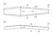
図2、図7(a)、(b)に示すようにクロスメンバー20は、金属材料としての高張力鋼板がプレス成形されることにより、長手方向の中央部が折り曲げられて鞍型に形成されている。具体的に説明すると、クロスメンバー20のウエブ22は、長手方向に平板状に延出されるとともに、長手方向の中央部に折り曲げ部位23が前記プレス成形により形成されている。折り曲げ部位23の折り曲げ角度θは、図7(a)に示すように鈍角である。
As shown in FIG. 1, the
As shown in FIGS. 2, 7 (a) and 7 (b), the
又、ウエブ22は、図2及び図7(b)に示すように長手方向の両端から、前記中央部の折り曲げ部位23に行くほど徐々にリニアに幅方向が広がるように形成されている。すなわち、ウエブ22は、端部から折り曲げ部位23に向けてその幅方向長さが徐々に長くなるようになっている。このため、ウエブ22の側縁22a,22bは端部から折り曲げ部位23までは直線状に形成されている。本実施形態では、ウエブ22の幅方向に位置する一対の側縁22a,22bは、平面視した際に、長手方向に延びる中心線Lを対称軸にして線対称となるように形成されている。すなわち、図7(b)に示すように、折り曲げ部位23を挟むようにして位置する左右の側縁22aの角度α1は、鈍角となるように形成されている。
Further, as shown in FIGS. 2 and 7B, the
又、図7(b)に示すように、折り曲げ部位23を挟むようにして位置する左右の側縁22bの角度α2は、鈍角となるように形成されている。本実施形態では、α1とα2とは同一角度となっている。又、本実施形態では、θ=α1=α2としている。
Further, as shown in FIG. 7B, the angle α2 of the left and right side edges 22b positioned so as to sandwich the
前記ウエブ22の両側縁からは、ウエブ22の折れ曲がり方向とは反対方向へそれぞれ一対の側壁24,26がウエブ22に対して直交する方向に立設されている。側壁24,26の長手方向の中央部には、折り曲げ部位23に連続するように折り曲げ部位24a,26aが形成されている。前記両側壁24,26の先端には、側壁の立設された方向とは直交する方向であって、互いに離間する方向にフランジ部28,30が張出しされている。フランジ部28,30において、長手方向の中央部には、折り曲げ部位31,32が形成されている。本実施形態では、側壁24,26のウエブ22からの上下幅(高さ)は、長手方向全体に亘って同じ幅を有している。
From both side edges of the
そして、上記のようにウエブ22、側壁24,26、フランジ部28,30が形成されていることにより、クロスメンバー20は、横断面がいわゆるハット形状に形成されている。
And since the
(プレス装置について)
次に、前記クロスメンバー20をプレス成形するプレス装置を図3〜6を参照して説明する。
(About press equipment)
Next, a press apparatus for press-molding the
図3に示すようにプレス装置において、図示しないベッドに固定された下型72にはダイ73が固定されている。ダイ73の加工穴74にはクッション75で支えられたカウンタホルダ76が出没可能に設けられている。図6に示すようにカウンタホルダ76の上面77には、前記ウエブ22の折り曲げ部位23を形成するための頂部78と、前記頂部78を挟んで互いに反対方向へ向かって斜状に下がる一対のプレス面79,80を有する。一対のプレス面79,80間の角度はθとなっている。前記加工穴74の入口は曲げ肩81が設けられている。
As shown in FIG. 3, in the press apparatus, a
又、図6に示すように、ダイ73の上面82において、前記加工穴74の上部開口を挟む一対の部位は、折り曲げ部位31,32を形成するための一対の頂部83となっている。又、ダイ73の上面82において、前記頂部83を挟んで互いに反対方向へ向かって斜状に下がる一対のプレス面84,85を有する。一対のプレス面84,85間の角度はθとなっている。
As shown in FIG. 6, on the
図示しない上型には前記カウンタホルダ76に対峙するようにポンチ86が固定されている。ポンチ86は、ダイ73の加工穴74に対応する大きさと断面形状を備える。又、図5(a)、(b)に示すようにポンチ86の下面には、カウンタホルダ76の頂部78,プレス面79,80にそれぞれ対応した内頂部87、プレス面88,89が形成されている。
A
図3に示すように、ポンチ86の先端には曲げ肩81と協働してウエブ22と側壁24,26の境界である折り曲げ部を形成するための曲げ肩90が形成されている。又、ポンチ86の基端部には、図3に示すように、一対の肩部92,93が形成されている。肩部92,93は、長手方向の中央部には、ダイ73の頂部83、プレス面84、85と対応する形状を有する。
As shown in FIG. 3, a bending
上記プレス装置を使用して、クロスメンバー20を成形する場合、高張力鋼板Kを、加工穴74から上方に位置させたカウンタホルダ76とポンチ86とにより、図5(a)に示すように、挟み込み固定するとともに、図5(b)に示すように、プレス面79,88、プレス面80,89により、高張力鋼板Kが長手方向の中央部にて折り曲げ形成される。この折り曲げ部位の角度はθである。
When the
図5(b)の状態から、前記図示しない上型を下降させて、ポンチ86とカウンタホルダ76とで挟持された状態の高張力鋼板Kを下降させる。
そして、下降するポンチ86がダイ73の加工穴74に進入すると、高張力鋼板Kにおいて、ウエブ22となる部分がそのまま加工穴74に入り、側壁24,26となる部分がポンチの側面と加工穴74の内側面とにより挟まれつつダイ73内に引き込まれる。このとき、側壁24,26となる部分の長手方向の中央部は、たるみが生じる。このたるみは、ポンチ86がさらに下降することにより、加工穴74の内側面とポンチ86の側面により制御されて、ポンチ86が下死点に達するときまでに押しつぶされ、折り曲げ部位31,32がそれぞれ形成される。又、高張力鋼板Kのフランジ部となる部分は、ポンチ86の肩部92と、ダイ73の頂部83,プレス面84,85により、フランジ部28,30が形成される。
From the state of FIG. 5B, the upper mold (not shown) is lowered, and the high-tensile steel plate K held by the
Then, when the descending
以上のようにして横断面がいわゆるハット形状となるクロスメンバー20が形成される。このプレス成形が終了後、前記図示しない上型が上昇することによってクロスメンバー20はポンチ86により上昇した後、ポンチ86から取り外される。
As described above, the
(作用)
さて、上記のように構成されたクロスメンバー20のウエブ22は、図2及び図7(b)に示すように長手方向の両端から、前記中央部の折り曲げ部位23に行くほど徐々にリニアに幅方向が広がるように形成されている。このようにクロスメンバー20の形状を有することにより、プレス装置の金型構造は複雑な構成にすることなく、クロスメンバー20を形成できる。又、上記のように、折り曲げ部位23、31,32が形成されることにより、すなわち、鈍角である角度θ、α1,α2を有するように形成されていることにより、材料の伸び縮みを抑制した形状にすることができる。このため、高張力鋼板Kの伸び縮みを少なくすることができて成形性、軽量化ができる。
(Function)
As shown in FIGS. 2 and 7B, the
この実施形態によれば、以下のような効果を得ることができる。
(1) 本実施形態のクロスメンバー20は、ウエブ22の長手方向の両端からそれぞれウエブ22の折り曲げ部位23に亘って、ウエブ22の幅方向長さが徐々に長くなるようにウエブ22が形成されている。この結果、プレス装置の金型構造を複雑にすることなく、材料の伸び縮みを抑制した形状にすることができる。
According to this embodiment, the following effects can be obtained.
(1) In the
(2) 本実施形態のクロスメンバー20のウエブ22の側縁が、ウエブ22の長手方向の各端部からウエブ22の折り曲げ部位23まで直線状に形成しても、上記(1)の効果を奏する。
(2) Even if the side edge of the
(3) 本実施形態では、ウエブ22の折り曲げ部位23がウエブ22の中央部のクロスメンバーとした場合においても、上記(1)の効果を奏する。
(4) 本実施形態では、両側壁24,26は、ウエブ22の折り曲げ部位23において、折り曲げられており、ウエブ22の折り曲げ部位23の折り曲げ角度θと、両側壁24,26の折り曲げ角度α1,α2を等しくすることにより、幾何学的に、材料の伸び縮みが最も抑制した形状にすることができる。
(3) In this embodiment, even when the
(4) In the present embodiment, the
(5) 本実施形態はクロスメンバーの材料として広く使用されている高張力鋼板としたことにより、このため、高張力鋼板の伸び縮みを少なくすることができて成形性、軽量化を図ることかできる。 (5) Since the present embodiment is made of a high-tensile steel plate that is widely used as a material for the cross member, is it possible to reduce the expansion and contraction of the high-tensile steel plate and reduce formability and weight? it can.
なお、この実施形態は、次のように変更して具体化することも可能である。
・ 前記実施形態では、金属材料として高張力鋼板としたが、高張力鋼板に限定するものではなく、高張力鋼板以外の鉄鋼板であってもよく、又、鉄鋼以外の金属材料であってもよい。
In addition, this embodiment can also be changed and embodied as follows.
-In the said embodiment, although it was set as the high-tensile steel plate as a metal material, it is not limited to a high-tensile steel plate, Steel plates other than a high-tensile steel plate may be sufficient, and metal materials other than a steel plate may be sufficient. Good.
・ 前記実施形態では、ウエブ22の幅方向に位置する一対の側縁22a,22bは、平面視した際に、長手方向に延びる中心線Lを対称軸にして線対称となるように形成されているが、前記両側縁の配置は線対称に限定するものではない。すなわち、角度α1と角度α2を同一角度としたが、角度α1と角度α2は鈍角を維持していれば異なっていても良い。この場合においても、材料の伸び縮みを抑制した形状にすることができる。
In the embodiment, the pair of
・ 又、角度α1=角度α2とし、θを角度α1と異なるようにし、それらの角度が全て鈍角を維持していれば異なっていても良い。この場合においても、材料の伸び縮みを抑制した形状にすることができる。 Further, the angle α1 = the angle α2, and θ may be different from the angle α1, and the angles may be different as long as all of the angles maintain an obtuse angle. Even in this case, it is possible to obtain a shape in which the expansion and contraction of the material is suppressed.
・ 前記実施形態では、側壁24,26のウエブ22からの高さは、長手方向全体に亘って、同じ高さを有するようにしているが、側壁24,26のウエブ22からの高さは、長手方向全体に亘って同じ高さである必要はなく、長手方向中央部から長手方向の端部側に行くほど低くしたり、長手方向の端部側に行くほど逆に高くするようにしてもよい。
-In the said embodiment, although the height from the
・ 図8に示すように、ウエブ22の長手方向の両端部の側壁24,26において、ウエブ側の基端よりも反ウエブ側の先端を開くように、すなわち、広くなるように形成してもよい。この場合、長手方向の中央部側の側壁24,26は前記実施形態と同様にウエブ22に対して直交するように形成され、長手方向の端部側に行くほど反ウエブ側の先端を開くように斜めになる。このように構成すると、クロスメンバー20をサイドメンバー50間に連結して使用する際、側突強度を向上することができる。
As shown in FIG. 8, the
・ 前記実施形態では、ウエブ22の長手方向の中央部に一箇所のみ折り曲げ部位23を形成したが、折り曲げ部位の設ける場所は1箇所に限定するものではなく、複数箇所に折り曲げ部位を設けても良い。図9(a)は、ウエブ22の長手方向において、複数箇所に折り曲げ部位23a〜23dを端部Rから順に形成した一例である。
-In the said embodiment, although the bending
図9(a)では、折り曲げ部位23b,23cが長手方向の中央部に近位にそれぞれ位置し、折り曲げ部位23b,23c間の領域P1の幅M1は一定の値としている。折り曲げ部位23b,23a間の領域P2は、端部R側に行くほど幅M2が短くなるようにされている。折り曲げ部位23aから端部Rまでの領域P3は、端部Rに行くほど幅M3が短くなるようにされている。
In FIG. 9 (a), the
又、折り曲げ部位23c,23d間の領域P4は、端部Sに行くほど幅M4が短くなるようにされている。折り曲げ部位23dから端部Sまでの領域P5は、端部Sに行くほど幅M5が短くなるようにされている。又、各折り曲げ部位23a〜23dは、隣接する領域に対して、それぞれ鈍角の折り曲げ角度θ1〜θ4となるように形成されている。
In addition, the region P4 between the
又、各側壁24,26、フランジ部28,30には、ウエブ22の折り曲げ部位23a〜23dに対応して、それぞれ折り曲げ部位が形成されている。
このように形成した場合、図9(c)に示すように、ウエブ22の側縁は、折れ線状に形成される。このように構成しても、前記実施形態と同様の効果を奏することができる。
The
When formed in this way, as shown in FIG. 9C, the side edge of the
・ 図10に示すように、前記実施形態では、ウエブ22の長手方向の中央部に一箇所のみ折り曲げ部位23を形成したが、折り曲げ部位の設ける場所は明確に折れ線を有するように形成することに限定されるものではなく、湾曲するように形成してもよい。図10は、クロスメンバー20のウエブ22、側壁24,26、フランジ部28,30の長手方向の中央部をアールを有するように湾曲形成したものである。湾曲した部位の領域が折り曲げ部位95となる。
-As shown in FIG. 10, in the said embodiment, although the bending site |
この場合、図10(b)に示すように湾曲した折り曲げ部位95に隣接するウエブ22の平坦部分からそれぞれ延びる接線が交差する角度θが折れ曲がり角度となる。この角度θは鈍角である。
In this case, as shown in FIG. 10B, the angle θ at which the tangent lines extending from the flat portion of the
又、図10(c)に示すように湾曲した折り曲げ部位95に対応する側壁24,26の折り曲げ部位においては、この折り曲げ部位に隣接する平坦部分からそれぞれ延びる接線が交差する角度α1,α2が折れ曲がり角度となる。この角度α1,α2は鈍角である。このθ,α1,α2の関係は、既に他の実施形態で述べた関係であればよい。
Further, as shown in FIG. 10 (c), at the bent portions of the
・ 前記実施形態では、ウエブ22の折り曲げ部位23は、長手方向の中央部に設けたが、折り曲げ部位23は中央部に限定されるものではない。例えば、図11(a)、及び図11(b)に示すように、ウエブ22の折り曲げ部位23を中央部から一方の端部側に偏位した位置に形成してもよい。
-In above-mentioned embodiment, although the bending site |
θ,α1,α2,θ1−θ4…折り曲げ角度、
K…高張力鋼板、R,S…端部、
22…ウエブ、22a,22b…側縁、
23,23a〜23d,24a,26a,31,32,95…折り曲げ部位、
24,26…側壁、28,30…フランジ部。
θ, α1, α2, θ1-θ4 ... bending angle,
K: high-tensile steel plate, R, S: end,
22 ... Web, 22a, 22b ... Side edge,
23, 23a to 23d, 24a, 26a, 31, 32, 95 ... bent portions,
24, 26 ... sidewalls, 28, 30 ... flanges.
Claims (6)
前記ウエブの長手方向の両端からそれぞれ前記ウエブの折り曲げ部位に亘って、前記ウエブの幅方向長さが徐々に長くなるように前記ウエブが形成されていることを特徴とする金属製車両用クロスメンバー。 A longitudinally extending web, a pair of side walls erected from both side edges in the width direction of the web, and a flange portion formed to project from the pair of side walls in a direction away from each other, in the longitudinal direction of the web, The web is a metal vehicle cross member bent into a saddle shape,
A cross member for a metal vehicle, wherein the web is formed so that the length in the width direction of the web gradually increases from both ends in the longitudinal direction of the web to the bent portion of the web. .
前記ウエブの折り曲げ部位の折り曲げ角度と、前記両側壁の折り曲げ角度が等しいことを特徴とする請求項1乃至請求項3のうちいずれか1項に記載の金属製車両用クロスメンバー。 The both side walls are bent at the bent portion of the web,
The metal vehicle cross member according to any one of claims 1 to 3, wherein a bending angle of a bent portion of the web is equal to a bending angle of the both side walls.
Priority Applications (1)
| Application Number | Priority Date | Filing Date | Title |
|---|---|---|---|
| JP2010262657A JP5459183B2 (en) | 2010-11-25 | 2010-11-25 | Metal vehicle cross member |
Applications Claiming Priority (1)
| Application Number | Priority Date | Filing Date | Title |
|---|---|---|---|
| JP2010262657A JP5459183B2 (en) | 2010-11-25 | 2010-11-25 | Metal vehicle cross member |
Publications (2)
| Publication Number | Publication Date |
|---|---|
| JP2012111377A true JP2012111377A (en) | 2012-06-14 |
| JP5459183B2 JP5459183B2 (en) | 2014-04-02 |
Family
ID=46496066
Family Applications (1)
| Application Number | Title | Priority Date | Filing Date |
|---|---|---|---|
| JP2010262657A Expired - Fee Related JP5459183B2 (en) | 2010-11-25 | 2010-11-25 | Metal vehicle cross member |
Country Status (1)
| Country | Link |
|---|---|
| JP (1) | JP5459183B2 (en) |
Citations (11)
| Publication number | Priority date | Publication date | Assignee | Title |
|---|---|---|---|---|
| JPH01145581U (en) * | 1988-03-14 | 1989-10-06 | ||
| JPH06154897A (en) * | 1992-11-20 | 1994-06-03 | Fuji Heavy Ind Ltd | Press die |
| JPH06246355A (en) * | 1993-02-26 | 1994-09-06 | F Tech:Kk | Method for bending high tensile steel sheet |
| JPH06263058A (en) * | 1993-03-10 | 1994-09-20 | Mitsubishi Motors Corp | Cross member for undercarriage frame |
| JP2007021568A (en) * | 2005-07-21 | 2007-02-01 | Nippon Steel Corp | Method for forming member of hat-shaped section having excellent shape freezing property |
| JP2008073697A (en) * | 2006-09-19 | 2008-04-03 | Nippon Steel Corp | Method for designing die for two-stage press forming excellent in shape fixability |
| JP2009202189A (en) * | 2008-02-27 | 2009-09-10 | Nippon Steel Corp | Metallic member having hat-shaped cross section and having bent part in plane in longitudinal direction of member |
| JP2009248087A (en) * | 2008-04-01 | 2009-10-29 | Nippon Steel Corp | Hat-shaped cross-sectional member made of metal having bent part out of plane in longitudinal direction of member and method of press-forming the same |
| JP2010082660A (en) * | 2008-09-30 | 2010-04-15 | Nippon Steel Corp | Press-forming apparatus and press-forming method |
| JP2010215092A (en) * | 2009-03-17 | 2010-09-30 | Mazda Motor Corp | Lower part structure of vehicle body |
| JP2010228642A (en) * | 2009-03-27 | 2010-10-14 | Mazda Motor Corp | Lower vehicle-body structure of vehicle |
-
2010
- 2010-11-25 JP JP2010262657A patent/JP5459183B2/en not_active Expired - Fee Related
Patent Citations (11)
| Publication number | Priority date | Publication date | Assignee | Title |
|---|---|---|---|---|
| JPH01145581U (en) * | 1988-03-14 | 1989-10-06 | ||
| JPH06154897A (en) * | 1992-11-20 | 1994-06-03 | Fuji Heavy Ind Ltd | Press die |
| JPH06246355A (en) * | 1993-02-26 | 1994-09-06 | F Tech:Kk | Method for bending high tensile steel sheet |
| JPH06263058A (en) * | 1993-03-10 | 1994-09-20 | Mitsubishi Motors Corp | Cross member for undercarriage frame |
| JP2007021568A (en) * | 2005-07-21 | 2007-02-01 | Nippon Steel Corp | Method for forming member of hat-shaped section having excellent shape freezing property |
| JP2008073697A (en) * | 2006-09-19 | 2008-04-03 | Nippon Steel Corp | Method for designing die for two-stage press forming excellent in shape fixability |
| JP2009202189A (en) * | 2008-02-27 | 2009-09-10 | Nippon Steel Corp | Metallic member having hat-shaped cross section and having bent part in plane in longitudinal direction of member |
| JP2009248087A (en) * | 2008-04-01 | 2009-10-29 | Nippon Steel Corp | Hat-shaped cross-sectional member made of metal having bent part out of plane in longitudinal direction of member and method of press-forming the same |
| JP2010082660A (en) * | 2008-09-30 | 2010-04-15 | Nippon Steel Corp | Press-forming apparatus and press-forming method |
| JP2010215092A (en) * | 2009-03-17 | 2010-09-30 | Mazda Motor Corp | Lower part structure of vehicle body |
| JP2010228642A (en) * | 2009-03-27 | 2010-10-14 | Mazda Motor Corp | Lower vehicle-body structure of vehicle |
Also Published As
| Publication number | Publication date |
|---|---|
| JP5459183B2 (en) | 2014-04-02 |
Similar Documents
| Publication | Publication Date | Title |
|---|---|---|
| KR102407168B1 (en) | The manufacturing method and manufacturing device of the press parts | |
| EP2896467B1 (en) | Method for producing curved article | |
| TWI555593B (en) | Blank, formed plate,and method for manufacturing press formed product | |
| JP5569661B2 (en) | Manufacturing method and manufacturing apparatus of press-molded body | |
| US11020785B2 (en) | Method and apparatus for manufacturing press component | |
| JP6052479B1 (en) | PRESS-MOLDED PRODUCTION METHOD, PRESS-MOLDED PRODUCT, AND PRESS DEVICE | |
| US20150273563A1 (en) | Method for producing center pillar reinforcement | |
| TWI619564B (en) | Method for manufacturing press molded product and press die | |
| KR102138043B1 (en) | Blank, and method for producing press-molded article | |
| JP6135829B2 (en) | Manufacturing method of press-molded product and press-molded product | |
| JP6032373B2 (en) | Manufacturing method and press molding apparatus for structural member for automobile body | |
| TWI590885B (en) | A method of manufacturing a press-formed product and a press-formed product, and a manufacturing apparatus of the press-formed product | |
| RU2706253C1 (en) | Extruded vehicle body component and method of its manufacturing | |
| WO2016171229A1 (en) | Method for producing press-molded product, press-molded product, and pressing device | |
| JP6094699B2 (en) | PRESS-MOLDED PRODUCTION METHOD, PRESS-MOLDED PRODUCT, AND PRESS DEVICE | |
| JP6665612B2 (en) | Method for manufacturing press-formed product and press device | |
| JP5079604B2 (en) | Metal mold for press forming of cross-section hat-shaped member and press molding method | |
| JP6265315B1 (en) | Press-molded parts for automobile bodies and methods for producing the same | |
| JP5459183B2 (en) | Metal vehicle cross member | |
| KR102450454B1 (en) | Press forming method | |
| JP6759645B2 (en) | Method for manufacturing press-formed products and press equipment | |
| JP2015074354A (en) | Structure member for vehicle body made of high tensile steel plate and welded structure body | |
| JP7273355B1 (en) | Structural member and its manufacturing method | |
| JP2022173890A (en) | Manufacturing method of vehicle press component | |
| JP2021169268A (en) | Vehicle strength member |
Legal Events
| Date | Code | Title | Description |
|---|---|---|---|
| A621 | Written request for application examination |
Free format text: JAPANESE INTERMEDIATE CODE: A621 Effective date: 20130208 |
|
| A977 | Report on retrieval |
Free format text: JAPANESE INTERMEDIATE CODE: A971007 Effective date: 20131210 |
|
| TRDD | Decision of grant or rejection written | ||
| A01 | Written decision to grant a patent or to grant a registration (utility model) |
Free format text: JAPANESE INTERMEDIATE CODE: A01 Effective date: 20131217 |
|
| A61 | First payment of annual fees (during grant procedure) |
Free format text: JAPANESE INTERMEDIATE CODE: A61 Effective date: 20131230 |
|
| R150 | Certificate of patent or registration of utility model |
Ref document number: 5459183 Country of ref document: JP Free format text: JAPANESE INTERMEDIATE CODE: R150 Free format text: JAPANESE INTERMEDIATE CODE: R150 |
|
| R250 | Receipt of annual fees |
Free format text: JAPANESE INTERMEDIATE CODE: R250 |
|
| R250 | Receipt of annual fees |
Free format text: JAPANESE INTERMEDIATE CODE: R250 |
|
| R250 | Receipt of annual fees |
Free format text: JAPANESE INTERMEDIATE CODE: R250 |
|
| R250 | Receipt of annual fees |
Free format text: JAPANESE INTERMEDIATE CODE: R250 |
|
| R250 | Receipt of annual fees |
Free format text: JAPANESE INTERMEDIATE CODE: R250 |
|
| R250 | Receipt of annual fees |
Free format text: JAPANESE INTERMEDIATE CODE: R250 |
|
| LAPS | Cancellation because of no payment of annual fees |