WO2023120493A1 - 二次電池用正極及び二次電池 - Google Patents
二次電池用正極及び二次電池 Download PDFInfo
- Publication number
- WO2023120493A1 WO2023120493A1 PCT/JP2022/046745 JP2022046745W WO2023120493A1 WO 2023120493 A1 WO2023120493 A1 WO 2023120493A1 JP 2022046745 W JP2022046745 W JP 2022046745W WO 2023120493 A1 WO2023120493 A1 WO 2023120493A1
- Authority
- WO
- WIPO (PCT)
- Prior art keywords
- positive electrode
- active material
- lithium
- electrode active
- particles
- Prior art date
Links
- 239000002245 particle Substances 0.000 claims abstract description 119
- 239000007774 positive electrode material Substances 0.000 claims abstract description 58
- 239000002131 composite material Substances 0.000 claims abstract description 51
- 229910052744 lithium Inorganic materials 0.000 claims abstract description 47
- WHXSMMKQMYFTQS-UHFFFAOYSA-N Lithium Chemical compound [Li] WHXSMMKQMYFTQS-UHFFFAOYSA-N 0.000 claims abstract description 44
- 239000000203 mixture Substances 0.000 claims abstract description 40
- 238000000576 coating method Methods 0.000 claims abstract description 25
- 239000011248 coating agent Substances 0.000 claims abstract description 24
- 239000013078 crystal Substances 0.000 claims description 41
- 239000010408 film Substances 0.000 description 27
- 239000010410 layer Substances 0.000 description 22
- OKTJSMMVPCPJKN-UHFFFAOYSA-N Carbon Chemical compound [C] OKTJSMMVPCPJKN-UHFFFAOYSA-N 0.000 description 18
- 229910052751 metal Inorganic materials 0.000 description 11
- 230000000052 comparative effect Effects 0.000 description 10
- 230000006866 deterioration Effects 0.000 description 10
- 239000011255 nonaqueous electrolyte Substances 0.000 description 10
- 238000007789 sealing Methods 0.000 description 10
- 239000002184 metal Substances 0.000 description 9
- 238000010304 firing Methods 0.000 description 8
- -1 polytetrafluoroethylene Polymers 0.000 description 8
- 239000002002 slurry Substances 0.000 description 8
- 229910002804 graphite Inorganic materials 0.000 description 7
- 239000010439 graphite Substances 0.000 description 7
- 238000004519 manufacturing process Methods 0.000 description 7
- WMFOQBRAJBCJND-UHFFFAOYSA-M Lithium hydroxide Chemical compound [Li+].[OH-] WMFOQBRAJBCJND-UHFFFAOYSA-M 0.000 description 6
- 239000006230 acetylene black Substances 0.000 description 6
- 229910052782 aluminium Inorganic materials 0.000 description 6
- 239000011230 binding agent Substances 0.000 description 6
- 150000001875 compounds Chemical class 0.000 description 6
- 230000006835 compression Effects 0.000 description 6
- 238000007906 compression Methods 0.000 description 6
- 150000002736 metal compounds Chemical class 0.000 description 6
- 238000000034 method Methods 0.000 description 6
- 238000002156 mixing Methods 0.000 description 6
- 238000002360 preparation method Methods 0.000 description 6
- 239000003792 electrolyte Substances 0.000 description 5
- PXHVJJICTQNCMI-UHFFFAOYSA-N nickel Substances [Ni] PXHVJJICTQNCMI-UHFFFAOYSA-N 0.000 description 5
- 239000011164 primary particle Substances 0.000 description 5
- 150000003839 salts Chemical class 0.000 description 5
- 239000003125 aqueous solvent Substances 0.000 description 4
- 239000012298 atmosphere Substances 0.000 description 4
- 239000007773 negative electrode material Substances 0.000 description 4
- 229920002134 Carboxymethyl cellulose Polymers 0.000 description 3
- HBBGRARXTFLTSG-UHFFFAOYSA-N Lithium ion Chemical compound [Li+] HBBGRARXTFLTSG-UHFFFAOYSA-N 0.000 description 3
- SECXISVLQFMRJM-UHFFFAOYSA-N N-Methylpyrrolidone Chemical compound CN1CCCC1=O SECXISVLQFMRJM-UHFFFAOYSA-N 0.000 description 3
- 239000002033 PVDF binder Substances 0.000 description 3
- XAGFODPZIPBFFR-UHFFFAOYSA-N aluminium Chemical compound [Al] XAGFODPZIPBFFR-UHFFFAOYSA-N 0.000 description 3
- QVGXLLKOCUKJST-UHFFFAOYSA-N atomic oxygen Chemical compound [O] QVGXLLKOCUKJST-UHFFFAOYSA-N 0.000 description 3
- 229910052799 carbon Inorganic materials 0.000 description 3
- 239000003575 carbonaceous material Substances 0.000 description 3
- 239000004020 conductor Substances 0.000 description 3
- 239000011888 foil Substances 0.000 description 3
- 150000002641 lithium Chemical class 0.000 description 3
- 229910001416 lithium ion Inorganic materials 0.000 description 3
- 230000014759 maintenance of location Effects 0.000 description 3
- 229910052748 manganese Inorganic materials 0.000 description 3
- 239000011572 manganese Substances 0.000 description 3
- 229910052759 nickel Inorganic materials 0.000 description 3
- 239000001301 oxygen Substances 0.000 description 3
- 229910052760 oxygen Inorganic materials 0.000 description 3
- 229920002239 polyacrylonitrile Polymers 0.000 description 3
- 229920000098 polyolefin Polymers 0.000 description 3
- 229920002981 polyvinylidene fluoride Polymers 0.000 description 3
- VAYTZRYEBVHVLE-UHFFFAOYSA-N 1,3-dioxol-2-one Chemical compound O=C1OC=CO1 VAYTZRYEBVHVLE-UHFFFAOYSA-N 0.000 description 2
- 229920000178 Acrylic resin Polymers 0.000 description 2
- 239000004925 Acrylic resin Substances 0.000 description 2
- RYGMFSIKBFXOCR-UHFFFAOYSA-N Copper Chemical compound [Cu] RYGMFSIKBFXOCR-UHFFFAOYSA-N 0.000 description 2
- KMTRUDSVKNLOMY-UHFFFAOYSA-N Ethylene carbonate Chemical compound O=C1OCCO1 KMTRUDSVKNLOMY-UHFFFAOYSA-N 0.000 description 2
- 229910013870 LiPF 6 Inorganic materials 0.000 description 2
- 229920003171 Poly (ethylene oxide) Polymers 0.000 description 2
- 239000004642 Polyimide Substances 0.000 description 2
- 239000004372 Polyvinyl alcohol Substances 0.000 description 2
- 239000012300 argon atmosphere Substances 0.000 description 2
- 229910021383 artificial graphite Inorganic materials 0.000 description 2
- 239000002388 carbon-based active material Substances 0.000 description 2
- 229920002678 cellulose Polymers 0.000 description 2
- 239000001913 cellulose Substances 0.000 description 2
- 229910052802 copper Inorganic materials 0.000 description 2
- 239000010949 copper Substances 0.000 description 2
- 238000005336 cracking Methods 0.000 description 2
- JBTWLSYIZRCDFO-UHFFFAOYSA-N ethyl methyl carbonate Chemical compound CCOC(=O)OC JBTWLSYIZRCDFO-UHFFFAOYSA-N 0.000 description 2
- 239000007789 gas Substances 0.000 description 2
- 239000003273 ketjen black Substances 0.000 description 2
- 238000007561 laser diffraction method Methods 0.000 description 2
- XGZVUEUWXADBQD-UHFFFAOYSA-L lithium carbonate Chemical compound [Li+].[Li+].[O-]C([O-])=O XGZVUEUWXADBQD-UHFFFAOYSA-L 0.000 description 2
- 229910052808 lithium carbonate Inorganic materials 0.000 description 2
- IIPYXGDZVMZOAP-UHFFFAOYSA-N lithium nitrate Chemical compound [Li+].[O-][N+]([O-])=O IIPYXGDZVMZOAP-UHFFFAOYSA-N 0.000 description 2
- VNWKTOKETHGBQD-UHFFFAOYSA-N methane Chemical compound C VNWKTOKETHGBQD-UHFFFAOYSA-N 0.000 description 2
- 239000012046 mixed solvent Substances 0.000 description 2
- 229920001721 polyimide Polymers 0.000 description 2
- 229920001343 polytetrafluoroethylene Polymers 0.000 description 2
- 239000004810 polytetrafluoroethylene Substances 0.000 description 2
- 229920002451 polyvinyl alcohol Polymers 0.000 description 2
- 239000002243 precursor Substances 0.000 description 2
- 239000002994 raw material Substances 0.000 description 2
- 229920005989 resin Polymers 0.000 description 2
- 239000011347 resin Substances 0.000 description 2
- 239000011163 secondary particle Substances 0.000 description 2
- 239000002904 solvent Substances 0.000 description 2
- 229920003048 styrene butadiene rubber Polymers 0.000 description 2
- 239000002344 surface layer Substances 0.000 description 2
- 238000003466 welding Methods 0.000 description 2
- 239000004215 Carbon black (E152) Substances 0.000 description 1
- PXGOKWXKJXAPGV-UHFFFAOYSA-N Fluorine Chemical compound FF PXGOKWXKJXAPGV-UHFFFAOYSA-N 0.000 description 1
- 229910002991 LiNi0.5Co0.2Mn0.3O2 Inorganic materials 0.000 description 1
- 240000007594 Oryza sativa Species 0.000 description 1
- 235000007164 Oryza sativa Nutrition 0.000 description 1
- 239000004698 Polyethylene Substances 0.000 description 1
- 239000004743 Polypropylene Substances 0.000 description 1
- 229920002125 Sokalan® Polymers 0.000 description 1
- OMOVVBIIQSXZSZ-UHFFFAOYSA-N [6-(4-acetyloxy-5,9a-dimethyl-2,7-dioxo-4,5a,6,9-tetrahydro-3h-pyrano[3,4-b]oxepin-5-yl)-5-formyloxy-3-(furan-3-yl)-3a-methyl-7-methylidene-1a,2,3,4,5,6-hexahydroindeno[1,7a-b]oxiren-4-yl] 2-hydroxy-3-methylpentanoate Chemical compound CC12C(OC(=O)C(O)C(C)CC)C(OC=O)C(C3(C)C(CC(=O)OC4(C)COC(=O)CC43)OC(C)=O)C(=C)C32OC3CC1C=1C=COC=1 OMOVVBIIQSXZSZ-UHFFFAOYSA-N 0.000 description 1
- HSFWRNGVRCDJHI-UHFFFAOYSA-N alpha-acetylene Natural products C#C HSFWRNGVRCDJHI-UHFFFAOYSA-N 0.000 description 1
- IZJSTXINDUKPRP-UHFFFAOYSA-N aluminum lead Chemical compound [Al].[Pb] IZJSTXINDUKPRP-UHFFFAOYSA-N 0.000 description 1
- 150000001408 amides Chemical class 0.000 description 1
- 239000007864 aqueous solution Substances 0.000 description 1
- 229910052788 barium Inorganic materials 0.000 description 1
- 230000005540 biological transmission Effects 0.000 description 1
- 229910052796 boron Inorganic materials 0.000 description 1
- 239000006229 carbon black Substances 0.000 description 1
- 239000002041 carbon nanotube Substances 0.000 description 1
- 229910021393 carbon nanotube Inorganic materials 0.000 description 1
- 239000001768 carboxy methyl cellulose Substances 0.000 description 1
- 235000010948 carboxy methyl cellulose Nutrition 0.000 description 1
- 239000008112 carboxymethyl-cellulose Substances 0.000 description 1
- 235000013339 cereals Nutrition 0.000 description 1
- 238000005229 chemical vapour deposition Methods 0.000 description 1
- 229910052804 chromium Inorganic materials 0.000 description 1
- 238000000975 co-precipitation Methods 0.000 description 1
- 239000011300 coal pitch Substances 0.000 description 1
- 229910000361 cobalt sulfate Inorganic materials 0.000 description 1
- 229940044175 cobalt sulfate Drugs 0.000 description 1
- KTVIXTQDYHMGHF-UHFFFAOYSA-L cobalt(2+) sulfate Chemical compound [Co+2].[O-]S([O-])(=O)=O KTVIXTQDYHMGHF-UHFFFAOYSA-L 0.000 description 1
- 238000010280 constant potential charging Methods 0.000 description 1
- 238000010277 constant-current charging Methods 0.000 description 1
- 239000011889 copper foil Substances 0.000 description 1
- 238000009831 deintercalation Methods 0.000 description 1
- 238000003795 desorption Methods 0.000 description 1
- IEJIGPNLZYLLBP-UHFFFAOYSA-N dimethyl carbonate Chemical compound COC(=O)OC IEJIGPNLZYLLBP-UHFFFAOYSA-N 0.000 description 1
- 238000009826 distribution Methods 0.000 description 1
- 230000000694 effects Effects 0.000 description 1
- 150000002148 esters Chemical class 0.000 description 1
- 150000002170 ethers Chemical class 0.000 description 1
- 125000002534 ethynyl group Chemical group [H]C#C* 0.000 description 1
- 229910052731 fluorine Inorganic materials 0.000 description 1
- 239000011737 fluorine Substances 0.000 description 1
- 239000006232 furnace black Substances 0.000 description 1
- 125000005843 halogen group Chemical group 0.000 description 1
- 230000020169 heat generation Effects 0.000 description 1
- 238000010438 heat treatment Methods 0.000 description 1
- 229930195733 hydrocarbon Natural products 0.000 description 1
- 150000002430 hydrocarbons Chemical class 0.000 description 1
- 125000004435 hydrogen atom Chemical group [H]* 0.000 description 1
- XLYOFNOQVPJJNP-UHFFFAOYSA-M hydroxide Chemical compound [OH-] XLYOFNOQVPJJNP-UHFFFAOYSA-M 0.000 description 1
- 238000003780 insertion Methods 0.000 description 1
- 230000037431 insertion Effects 0.000 description 1
- 238000009413 insulation Methods 0.000 description 1
- 238000009830 intercalation Methods 0.000 description 1
- 230000010220 ion permeability Effects 0.000 description 1
- 229910052742 iron Inorganic materials 0.000 description 1
- 238000010030 laminating Methods 0.000 description 1
- 229910052745 lead Inorganic materials 0.000 description 1
- HEPLMSKRHVKCAQ-UHFFFAOYSA-N lead nickel Chemical compound [Ni].[Pb] HEPLMSKRHVKCAQ-UHFFFAOYSA-N 0.000 description 1
- 239000011244 liquid electrolyte Substances 0.000 description 1
- 229910003002 lithium salt Inorganic materials 0.000 description 1
- 159000000002 lithium salts Chemical class 0.000 description 1
- 229910052749 magnesium Inorganic materials 0.000 description 1
- 229940099596 manganese sulfate Drugs 0.000 description 1
- 235000007079 manganese sulphate Nutrition 0.000 description 1
- 239000011702 manganese sulphate Substances 0.000 description 1
- SQQMAOCOWKFBNP-UHFFFAOYSA-L manganese(II) sulfate Chemical compound [Mn+2].[O-]S([O-])(=O)=O SQQMAOCOWKFBNP-UHFFFAOYSA-L 0.000 description 1
- 239000000463 material Substances 0.000 description 1
- 229910000000 metal hydroxide Inorganic materials 0.000 description 1
- 150000004692 metal hydroxides Chemical class 0.000 description 1
- 229910044991 metal oxide Inorganic materials 0.000 description 1
- 150000004706 metal oxides Chemical class 0.000 description 1
- 239000011325 microbead Substances 0.000 description 1
- 229910052750 molybdenum Inorganic materials 0.000 description 1
- 229910021382 natural graphite Inorganic materials 0.000 description 1
- LGQLOGILCSXPEA-UHFFFAOYSA-L nickel sulfate Chemical compound [Ni+2].[O-]S([O-])(=O)=O LGQLOGILCSXPEA-UHFFFAOYSA-L 0.000 description 1
- 229940053662 nickel sulfate Drugs 0.000 description 1
- 229910000363 nickel(II) sulfate Inorganic materials 0.000 description 1
- 229910052758 niobium Inorganic materials 0.000 description 1
- 150000002825 nitriles Chemical class 0.000 description 1
- 239000004745 nonwoven fabric Substances 0.000 description 1
- 230000002093 peripheral effect Effects 0.000 description 1
- 239000011301 petroleum pitch Substances 0.000 description 1
- 239000005011 phenolic resin Substances 0.000 description 1
- 229920000573 polyethylene Polymers 0.000 description 1
- 229920000642 polymer Polymers 0.000 description 1
- 229920001155 polypropylene Polymers 0.000 description 1
- 229910052700 potassium Inorganic materials 0.000 description 1
- 235000009566 rice Nutrition 0.000 description 1
- 229910052706 scandium Inorganic materials 0.000 description 1
- 229910052710 silicon Inorganic materials 0.000 description 1
- 239000002409 silicon-based active material Substances 0.000 description 1
- 239000002356 single layer Substances 0.000 description 1
- 229910052708 sodium Inorganic materials 0.000 description 1
- 239000007784 solid electrolyte Substances 0.000 description 1
- 229910052712 strontium Inorganic materials 0.000 description 1
- 239000010409 thin film Substances 0.000 description 1
- 229910052718 tin Inorganic materials 0.000 description 1
- 229910052719 titanium Inorganic materials 0.000 description 1
- XLYOFNOQVPJJNP-UHFFFAOYSA-N water Substances O XLYOFNOQVPJJNP-UHFFFAOYSA-N 0.000 description 1
- 239000002759 woven fabric Substances 0.000 description 1
- 229910052727 yttrium Inorganic materials 0.000 description 1
- 229910052725 zinc Inorganic materials 0.000 description 1
- 229910052726 zirconium Inorganic materials 0.000 description 1
Images
Classifications
-
- H—ELECTRICITY
- H01—ELECTRIC ELEMENTS
- H01M—PROCESSES OR MEANS, e.g. BATTERIES, FOR THE DIRECT CONVERSION OF CHEMICAL ENERGY INTO ELECTRICAL ENERGY
- H01M4/00—Electrodes
- H01M4/02—Electrodes composed of, or comprising, active material
- H01M4/13—Electrodes for accumulators with non-aqueous electrolyte, e.g. for lithium-accumulators; Processes of manufacture thereof
- H01M4/131—Electrodes based on mixed oxides or hydroxides, or on mixtures of oxides or hydroxides, e.g. LiCoOx
-
- H—ELECTRICITY
- H01—ELECTRIC ELEMENTS
- H01M—PROCESSES OR MEANS, e.g. BATTERIES, FOR THE DIRECT CONVERSION OF CHEMICAL ENERGY INTO ELECTRICAL ENERGY
- H01M4/00—Electrodes
- H01M4/02—Electrodes composed of, or comprising, active material
- H01M4/36—Selection of substances as active materials, active masses, active liquids
- H01M4/48—Selection of substances as active materials, active masses, active liquids of inorganic oxides or hydroxides
- H01M4/50—Selection of substances as active materials, active masses, active liquids of inorganic oxides or hydroxides of manganese
- H01M4/505—Selection of substances as active materials, active masses, active liquids of inorganic oxides or hydroxides of manganese of mixed oxides or hydroxides containing manganese for inserting or intercalating light metals, e.g. LiMn2O4 or LiMn2OxFy
-
- H—ELECTRICITY
- H01—ELECTRIC ELEMENTS
- H01M—PROCESSES OR MEANS, e.g. BATTERIES, FOR THE DIRECT CONVERSION OF CHEMICAL ENERGY INTO ELECTRICAL ENERGY
- H01M4/00—Electrodes
- H01M4/02—Electrodes composed of, or comprising, active material
- H01M4/36—Selection of substances as active materials, active masses, active liquids
- H01M4/48—Selection of substances as active materials, active masses, active liquids of inorganic oxides or hydroxides
- H01M4/52—Selection of substances as active materials, active masses, active liquids of inorganic oxides or hydroxides of nickel, cobalt or iron
- H01M4/525—Selection of substances as active materials, active masses, active liquids of inorganic oxides or hydroxides of nickel, cobalt or iron of mixed oxides or hydroxides containing iron, cobalt or nickel for inserting or intercalating light metals, e.g. LiNiO2, LiCoO2 or LiCoOxFy
-
- Y—GENERAL TAGGING OF NEW TECHNOLOGICAL DEVELOPMENTS; GENERAL TAGGING OF CROSS-SECTIONAL TECHNOLOGIES SPANNING OVER SEVERAL SECTIONS OF THE IPC; TECHNICAL SUBJECTS COVERED BY FORMER USPC CROSS-REFERENCE ART COLLECTIONS [XRACs] AND DIGESTS
- Y02—TECHNOLOGIES OR APPLICATIONS FOR MITIGATION OR ADAPTATION AGAINST CLIMATE CHANGE
- Y02E—REDUCTION OF GREENHOUSE GAS [GHG] EMISSIONS, RELATED TO ENERGY GENERATION, TRANSMISSION OR DISTRIBUTION
- Y02E60/00—Enabling technologies; Technologies with a potential or indirect contribution to GHG emissions mitigation
- Y02E60/10—Energy storage using batteries
Definitions
- the present disclosure relates to positive electrodes for secondary batteries and secondary batteries.
- Patent Documents 1 to 3 disclose the use of positive electrode active materials containing single-crystal particles and polycrystalline particles in order to improve battery performance. is disclosed. Further, Patent Documents 4 and 5 disclose techniques for coating the surfaces of positive electrode active material particles with carbon.
- the positive electrode when manufacturing a positive electrode, the positive electrode is compressed in order to increase the density of the positive electrode mixture layer containing the positive electrode active material. Occasionally, polycrystalline particles may crack. When the polycrystalline particles are cracked, the performance of the positive electrode active material is degraded, and the charge/discharge cycle characteristics are significantly degraded.
- the present disclosure provides a positive electrode for a secondary battery and a secondary battery that can suppress deterioration in the charge-discharge cycle characteristics of the secondary battery even when using a positive electrode active material containing single-crystal particles and polycrystalline particles. intended to provide
- a positive electrode for a secondary battery which is one aspect of the present disclosure, includes a positive electrode current collector and a positive electrode mixture layer disposed on the positive electrode current collector, wherein the positive electrode mixture layer is made of single crystal particles.
- a positive electrode active material A made of a lithium-containing composite oxide and a positive electrode active material B made of polycrystalline particles of a lithium-containing composite oxide, wherein the positive electrode active material A is a carbonaceous material covering the surfaces of the single crystal particles.
- the coating amount of the carbonaceous coating that has a coating and is coated on the surface of the single crystal particle is 1% by mass or more and 10% by mass or less with respect to the mass of the lithium-containing composite oxide of the single crystal particle,
- the amount of the carbonaceous coating coated on the surfaces of the polycrystalline particles is It is characterized by being less than the amount of the carbonaceous film to be coated.
- a secondary battery according to one aspect of the present disclosure includes the positive electrode for a secondary battery.
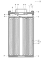
- FIG. 1 is a schematic cross-sectional view of a secondary battery that is an example of an embodiment
- FIG. 1 is a schematic cross-sectional view of a secondary battery that is an example of an embodiment.
- the battery case 15 is composed of a bottomed cylindrical case body 16 and a sealing member 17 that closes the opening of the case body 16 .
- the wound electrode body 14 another form of electrode body such as a stacked electrode body in which positive and negative electrodes are alternately stacked via a separator may be applied.
- Examples of the battery case 15 include cylindrical, rectangular, coin-shaped, button-shaped, and other metal cases, and resin cases formed by laminating resin sheets (so-called laminate type).
- the electrolyte may be an aqueous electrolyte, but is preferably a non-aqueous electrolyte containing a non-aqueous solvent and an electrolyte salt dissolved in the non-aqueous solvent.
- non-aqueous solvents include esters, ethers, nitriles, amides, and mixed solvents of two or more thereof.
- the non-aqueous solvent may contain a halogen-substituted product obtained by substituting at least part of the hydrogen atoms of these solvents with halogen atoms such as fluorine.
- a lithium salt such as LiPF 6 is used as the electrolyte salt.
- the electrolyte is not limited to a liquid electrolyte, and may be a solid electrolyte using a gel polymer or the like.
- the case body 16 is, for example, a bottomed cylindrical metal container.
- a gasket 28 is provided between the case body 16 and the sealing member 17 to ensure hermeticity inside the battery.
- the case main body 16 has an overhanging portion 22 that supports the sealing member 17, for example, a portion of the side surface overhanging inward.
- the protruding portion 22 is preferably annularly formed along the circumferential direction of the case body 16 and supports the sealing member 17 on the upper surface thereof.
- the sealing body 17 has a structure in which a filter 23, a lower valve body 24, an insulating member 25, an upper valve body 26, and a cap 27 are layered in order from the electrode body 14 side.
- Each member constituting the sealing member 17 has, for example, a disk shape or a ring shape, and each member except for the insulating member 25 is electrically connected to each other.
- the lower valve body 24 and the upper valve body 26 are connected to each other at their central portions, and an insulating member 25 is interposed between their peripheral edge portions.
- the lower valve body 24 deforms and breaks so as to push the upper valve body 26 upward toward the cap 27 side, breaking the lower valve body 24 and the upper valve body 26 .
- the current path between is interrupted.
- the upper valve body 26 is broken and the gas is discharged from the opening of the cap 27 .
- the positive electrode lead 20 attached to the positive electrode 11 extends through the through hole of the insulating plate 18 toward the sealing member 17
- the negative electrode lead 21 attached to the negative electrode 12 extends through the insulating plate 19 . It extends to the bottom side of the case body 16 through the outside.
- the positive electrode lead 20 is connected to the lower surface of the filter 23, which is the bottom plate of the sealing member 17, by welding or the like, and the cap 27, which is the top plate of the sealing member 17 electrically connected to the filter 23, serves as a positive electrode terminal.
- the negative lead 21 is connected to the inner surface of the bottom of the case body 16 by welding or the like, and the case body 16 serves as a negative terminal.
- the positive electrode 11, the negative electrode 12, and the separator 13 are described in detail below.
- the positive electrode 11 has a positive electrode current collector and a positive electrode mixture layer disposed on the positive electrode current collector.
- a foil of a metal such as aluminum that is stable in the potential range of the positive electrode 11, a film having the metal on the surface layer, or the like can be used.
- the positive electrode mixture layer is preferably provided on both sides of the positive electrode current collector.
- the positive electrode mixture layer contains a positive electrode active material.
- the positive electrode mixture layer may contain a binder, a conductive material, and the like.
- a positive electrode mixture slurry containing a positive electrode active material, a binder, a conductive material, and the like is applied on a positive electrode current collector, the coating film is dried, and then compressed to form a positive electrode mixture layer. on the positive electrode current collector.
- Examples of conductive materials contained in the positive electrode mixture layer include carbon materials such as carbon black, acetylene black, ketjen black, and graphite.
- Binders contained in the positive electrode mixture layer include fluororesins such as polytetrafluoroethylene (PTFE) and polyvinylidene fluoride (PVdF), polyacrylonitrile (PAN), polyimides, acrylic resins, polyolefins, and carboxymethylcellulose (CMC).
- fluororesins such as polytetrafluoroethylene (PTFE) and polyvinylidene fluoride (PVdF), polyacrylonitrile (PAN), polyimides, acrylic resins, polyolefins, and carboxymethylcellulose (CMC).
- cellulose derivatives such as salts thereof, polyethylene oxide (PEO), and the like are included.
- the positive electrode active material has a positive electrode active material A and a positive electrode active material B.
- the positive electrode active material A has a lithium-containing composite oxide of single crystal particles and a carbonaceous film covering the surface of the single crystal particles of the lithium-containing composite oxide.
- the positive electrode active material B has a lithium-containing composite oxide of polycrystalline particles.
- the lithium-containing composite oxide of single crystal particles is composed of a single particle, and no grain boundaries of primary particles are confirmed in the particle cross section observed by SEM.
- the lithium-containing composite oxide of polycrystalline particles is composed of secondary particles in which primary particles are agglomerated, and grain boundaries of the primary particles are confirmed in the particle cross section observed by SEM.
- the amount of the carbonaceous film coated on the surface of the single crystal particles of the lithium-containing composite oxide is 1% by mass or more and 10% by mass with respect to the mass of the lithium-containing composite oxide of the single crystal particles. % or less, preferably 2% by mass or more and 10% by mass or less.
- the positive electrode active material B may have a carbonaceous film covering the surface of the polycrystalline particles of the lithium-containing composite oxide. It must be less than the amount of the carbonaceous coating coated on the surface of the single crystal grain of the object. As described above, the positive electrode 11 is compressed during fabrication of the positive electrode 11 .
- the purpose of this compression is, for example, to increase the volumetric energy density of the positive electrode mixture layer by increasing the density thereof, so that a high pressure is applied to the positive electrode mixture layer during compression. Therefore, cracks may occur in the polycrystalline particles of the lithium-containing composite oxide due to compression during fabrication of the positive electrode. When the polycrystalline particles are cracked, the cracked portion becomes a new surface, and deterioration progresses from the new surface, resulting in faster deterioration of the performance of the positive electrode active material. As a result, the charge-discharge cycle characteristics of the battery tend to deteriorate.
- the surface of the single-crystal particles coated with the carbonaceous film is more slippery than the surface of the polycrystalline particles, so that the single-crystal particles that are hard to crack are applied to the polycrystalline particles. It is believed that the stress is relaxed. As a result, cracking of the polycrystalline particles is suppressed, so deterioration of the performance of the positive electrode active material is suppressed, and it is believed that deterioration in the charge-discharge cycle characteristics of the battery is suppressed.
- the thickness of the carbonaceous film coated on the surface of the single crystal particles of the lithium-containing composite oxide is, for example, preferably 0.5 nm or more and 10 nm or less, more preferably 0.8 nm or more and 8 nm or less. , 1 nm or more and 5 nm or less. If the thickness of the carbonaceous coating is less than the above lower limit, slippage during compression may decrease. In addition, when the thickness of the carbonaceous film exceeds the above upper limit, desorption/insertion of lithium ions from the positive electrode active material may be hindered.
- the coverage of the carbonaceous film on the single crystal particles is preferably 80% or more, more preferably 90% or more, and even more preferably 95% or more.
- TEM transmission electron microscope
- EDX Energy Dispersive X-ray analyzer
- the amount of the carbonaceous film covering the surface of the polycrystalline particles of the lithium-containing composite oxide increases, the difference in slipperiness between the single crystal particles and the polycrystalline particles becomes smaller when the positive electrode is compressed. As a result, the effect of relieving the stress applied to the polycrystalline particles is reduced, and cracking of the polycrystalline particles may occur. Therefore, in the positive electrode active material B, the amount of the carbonaceous coating that coats the surface of the polycrystalline particles of the lithium-containing composite oxide is the amount of the carbonaceous coating that coats the surface of the single-crystal particles of the lithium-containing composite oxide.
- the surfaces of the polycrystalline particles of the lithium-containing composite oxide are preferably not coated with a carbonaceous film. That is, it is preferable that the entire surface of the polycrystalline grain is exposed.
- the lithium-containing composite oxide of single-crystal particles and the lithium-containing composite oxide of polycrystalline particles may have the same composition or different compositions, and are not particularly limited.
- These lithium-containing composite oxides are, for example, Ni, Co, Mn, Al, Zr, B, Mg, Sc, Y, Ti, Fe, Cu, Zn, Cr, Pb, Sn, Na, K, Ba, Sr , Ca, W, Mo, Nb, Si, or the like.
- At least one of Al and Mn is preferably included in terms of
- the average particle size of single crystal particles is preferably in the range of 2 ⁇ m to 20 ⁇ m, for example.
- the average particle size of the polycrystalline particles is preferably in the range of, for example, 5 ⁇ m to 20 ⁇ m.
- the density of the positive electrode mixture layer may be improved as compared with the case where the average particle size is outside the above range.
- the average particle diameter of single-crystal particles and the average particle diameter of polycrystalline particles are volume-average particle diameters measured by a laser diffraction method, and are median diameters at which the volume integrated value is 50% in the particle diameter distribution.
- the average particle size of single crystal particles and the average particle size of polycrystalline particles can be measured by a laser diffraction method using, for example, MT3000II manufactured by Microtrac Bell Co., Ltd.
- a polycrystalline particle is preferably composed of, for example, 10,000 to 5,000,000 primary particles per particle.
- the polycrystalline particles are composed of 10,000 to 5,000,000 primary particles per particle, for example, miniaturization of the polycrystalline particles is suppressed, and deterioration in charge/discharge cycle characteristics may be further suppressed.
- the content ratio of the positive electrode active material A and the positive electrode active material B in the positive electrode mixture layer is, for example, in the range of 2:8 to 8:2 in mass ratio in order to further suppress the deterioration of the charge-discharge cycle characteristics. is preferred.
- the total amount of positive electrode active material A and positive electrode active material B is relative to the total amount of the positive electrode mixture layer. It is preferably 90% by mass or more, more preferably 95% by mass or more.
- a lithium-containing composite oxide can be obtained, for example, by mixing a Li compound and a metal compound other than Li and firing the mixture in an oxygen atmosphere.
- Li compounds include lithium hydroxide, lithium carbonate, and lithium nitrate.
- Metal compounds other than Li include metal oxides such as Ni, Co and Al, and metal hydroxides.
- the metal compound other than Li may contain one metal element, or may contain a plurality of metal elements.
- Preparation of single crystal particles and polycrystalline particles is possible, for example, by adjusting the mixing ratio of the Li compound and the metal compound other than Li.
- the mixing ratio of the metal compound other than Li and the Li compound is such that the molar ratio of the metal element other than Li: Li is 1.0: 1.02 to 1.02.
- a ratio in the range of 1.0:1.2 is preferable.
- the mixing ratio of the metal compound other than Li and the Li compound is set to a molar ratio of metal element other than Li to Li of 1.0:1. It is preferable that the ratio be in the range of 025 to 1.0:1.15. Even if the mixing ratio does not satisfy the above range, for example, it is possible to separately produce single-crystal particles and polycrystalline particles by adjusting the firing temperature as follows.
- the firing temperature of the raw material mixture when the lithium-containing composite oxide is obtained as single crystal particles, it is preferable to set the firing temperature of the raw material mixture within the range of 900°C to 1100°C.
- the firing temperature at this time is preferably 20 hours to 150 hours.
- the firing temperature of the raw material mixture is preferably in the range of 500°C to 800°C.
- the firing temperature at this time is preferably 10 hours to 150 hours.
- Examples of methods for coating the surface of single-crystal particles or polycrystalline particles with a carbonaceous film include particles such as single-crystal particles, carbon black, acetylene black, ketjen black, furnace black, graphite, carbon nanotubes, and the like.
- a carbon material is dry-mixed in a planetary mill, and then the obtained sample is fired in an inert atmosphere at a predetermined temperature for a predetermined time.
- the firing temperature is, for example, 400 to 700° C.
- the firing time is, for example, 30 minutes or longer.
- Other methods include, for example, a method of forming a carbonaceous film on the particle surface by a CVD method using a hydrocarbon gas such as acetylene and methane, and mixing coal pitch, petroleum pitch, phenol resin, etc. with particles such as single crystal particles. Then, a method of forming a carbonaceous film on the particle surface by heat treatment, and the like.
- the coating method of a carbonaceous film is not limited to these methods.
- the density of the positive electrode mixture layer is preferably 3.55 g/cc or more, more preferably 3.60 g/cc or more, in order to increase the volumetric energy density of the battery, for example.
- the negative electrode 12 has a negative electrode current collector and a negative electrode mixture layer provided on the surface of the negative electrode current collector.
- a foil of a metal such as copper that is stable in the potential range of the negative electrode 12, a film having the metal on the surface layer, or the like can be used.
- the negative electrode mixture layer is preferably provided on both sides of the negative electrode current collector.
- the negative electrode mixture layer contains, for example, a negative electrode active material and a binder.
- a negative electrode mixture slurry containing a negative electrode active material, a binder, and the like is applied onto a negative electrode current collector, the coating film is dried, and then compressed to form a negative electrode mixture layer on the negative electrode current collector. It can be made by forming on.
- the negative electrode active material is not particularly limited as long as it is capable of reversibly intercalating and deintercalating lithium ions, but it preferably contains a carbon-based active material.
- Suitable carbon-based active materials are graphite such as natural graphite such as flake graphite, massive graphite and earthy graphite, artificial graphite such as massive artificial graphite (MAG) and graphitized mesophase carbon microbeads (MCMB).
- the negative electrode active material may contain a Si-based active material composed of at least one of Si and a Si-containing compound.
- the binder may be, for example, fluororesin, PAN, polyimide, acrylic resin, polyolefin, etc., as in the case of the positive electrode 11, but styrene-butadiene rubber (SBR), CMC or its salt, polyacrylic acid (PAA) or salts thereof, polyvinyl alcohol (PVA), and the like.
- SBR styrene-butadiene rubber
- PAA polyacrylic acid
- PVA polyvinyl alcohol
- separator 13 for example, a porous sheet having ion permeability and insulation is used. Specific examples of porous sheets include microporous thin films, woven fabrics, and non-woven fabrics.
- material of the separator 13 polyolefins such as polyethylene and polypropylene, cellulose, and the like are suitable.
- the separator 13 may have either a single layer structure or a laminated structure. A heat-resistant layer or the like may be formed on the surface of the separator 13 .
- Example> [Preparation of Lithium-Containing Composite Oxide of Single Crystal Particles] Nickel sulfate, cobalt sulfate, and manganese sulfate were mixed in a predetermined ratio and uniformly mixed in an alkaline aqueous solution of pH 10 to 11 to obtain a precursor. This precursor and lithium carbonate were mixed and fired at 1000° C. for 15 hours in an oxygen atmosphere. The composition of this lithium-containing composite oxide was analyzed by ICP and found to be LiNi 0.5 Co 0.2 Mn 0.3 O 2 .
- NMP N-methyl-2-pyrrolidone
- the positive electrode mixture slurry was applied to both surfaces of a positive electrode current collector made of aluminum foil having a thickness of 15 ⁇ m, and the coating film was dried. The total amount of slurry applied to both surfaces was 560 g/m 2 .
- the obtained positive electrode was compressed using a roller until the positive electrode thickness became 171 ⁇ m and the positive electrode density became 3.59 g/cc, and cut into a predetermined electrode size. This was made into the positive electrode of the Example.
- [Preparation of negative electrode] 95 parts by mass of graphite particles, 5 parts by mass of Si oxide, 1 part by mass of carboxymethyl cellulose (CMC), 1 part by mass of styrene-butadiene rubber (SBR), and water were mixed to prepare a negative electrode mixture slurry. .
- the negative electrode mixture slurry was applied to both surfaces of a negative electrode current collector made of copper foil having a thickness of 10 ⁇ m, and the coating film was dried. The total amount of the negative electrode mixture slurry applied to both surfaces was 282 g/m 2 .
- the obtained negative electrode was compressed using a roller until the thickness of the negative electrode reached 138 ⁇ m, and cut into a predetermined electrode size.
- the lithium-containing composite oxide of the single crystal particles of Example 1 not coated with a carbonaceous film is used as the positive electrode active material A, and the lithium-containing composite oxide of the polycrystalline particles of Example 1 is coated with a carbonaceous film.
- a non-aqueous electrolyte secondary battery was produced in the same manner as in Example except that the positive electrode active material B was used.
- a specific method for producing the positive electrode active material B is as follows. The lithium-containing composite oxide of the polycrystalline particles of Example 1 and acetylene black were weighed at a mass ratio of 95:5, and dry-stirred at 200 rpm for 24 hours in a planetary mill. Then, the obtained carbon composite sample was heat-treated in an argon atmosphere at 550 ° C. for 1 hour, and the surface of the polycrystalline particles of the lithium-containing composite oxide was coated with a carbonaceous film of acetylene black, and the positive electrode active material was coated. Substance B was obtained.
- the example showed a higher capacity retention rate after the charge-discharge cycle test than the comparative examples 1-4. Therefore, according to the examples, it is possible to suppress the deterioration of the charge-discharge cycle characteristics of the secondary battery even when using a positive electrode active material containing single crystal particles and polycrystalline particles.
Abstract
本開示の一態様である二次電池用正極は、正極集電体と、前記正極集電体上に配置された正極合材層と、を備え、前記正極合材層は、単結晶粒子のリチウム含有複合酸化物からなる正極活物質Aと、多結晶粒子のリチウム含有複合酸化物からなる正極活物質Bとを含み、前記正極活物質Aは、前記単結晶粒子の表面を被覆する炭素質被膜を有し、前記単結晶粒子の表面に被覆される前記炭素質被膜の被覆量は、前記単結晶粒子のリチウム含有複合酸化物の質量に対して1質量%以上10質量%以下であり、前記正極活物質Bには、前記多結晶粒子の表面に炭素質被膜が被覆されていないことを特徴とする。
Description
本開示は、二次電池用正極及び二次電池に関する。
リチウムイオン二次電池等の二次電池用の正極活物質として、例えば、特許文献1~3には、電池性能を改善するために、単結晶粒子及び多結晶粒子を含む正極活物質を使用することが開示されている。また、特許文献4~5には、正極活物質の粒子表面を炭素で被覆する技術が開示されている。
ところで、正極を作製する際、正極活物質を含む正極合材層の密度を上げるために、正極を圧縮するが、単結晶粒子及び多結晶粒子を含む正極活物質が使用されていると、圧縮時に、多結晶粒子が割れる場合がある。多結晶粒子が割れると、正極活物質の性能が劣化して、充放電サイクル特性の低下が顕著となる。
そこで、本開示は、単結晶粒子及び多結晶粒子を含む正極活物質を使用しても、二次電池の充放電サイクル特性の低下を抑制することが可能な二次電池用正極及び二次電池を提供することを目的とする。
本開示の一態様である二次電池用正極は、正極集電体と、前記正極集電体上に配置された正極合材層と、を備え、前記正極合材層は、単結晶粒子のリチウム含有複合酸化物からなる正極活物質Aと、多結晶粒子のリチウム含有複合酸化物からなる正極活物質Bとを含み、前記正極活物質Aは、前記単結晶粒子の表面を被覆する炭素質被膜を有し、前記単結晶粒子の表面に被覆される前記炭素質被膜の被覆量は、前記単結晶粒子のリチウム含有複合酸化物の質量に対して1質量%以上10質量%以下であり、前記正極活物質Bにおいて、前記多結晶粒子の表面に炭素質被膜が被覆される場合、前記多結晶粒子の表面に被覆される前記炭素質被膜の被覆量は、前記単結晶粒子の表面に被覆される前記炭素質被膜の被覆量より少ないことを特徴とする。
本開示の一態様である二次電池は、上記二次電池用正極を備えることを特徴とする。
本開示によれば、単結晶粒子及び多結晶粒子を含む正極活物質を使用しても、二次電池の充放電サイクル特性の低下を抑制することができる。
以下に、本開示の一態様である二次電池の一例について説明する。
図1は、実施形態の一例である二次電池の模式断面図である。図1に示す二次電池10は、正極11及び負極12がセパレータ13を介して巻回されてなる巻回型の電極体14と、電解質と、電極体14の上下にそれぞれ配置された絶縁板18,19と、上記部材を収容する電池ケース15と、を備える。電池ケース15は、有底円筒形状のケース本体16と、ケース本体16の開口部を塞ぐ封口体17とにより構成される。なお、巻回型の電極体14の代わりに、正極及び負極がセパレータを介して交互に積層されてなる積層型の電極体など、他の形態の電極体が適用されてもよい。また、電池ケース15としては、円筒形、角形、コイン形、ボタン形等の金属製ケース、樹脂シートをラミネートして形成された樹脂製ケース(所謂ラミネート型)などが例示できる。
電解質は、水系電解質であってもよいが、好ましくは非水溶媒と、非水溶媒に溶解した電解質塩とを含む非水電解質である。非水溶媒には、例えばエステル類、エーテル類、ニトリル類、アミド類、及びこれらの2種以上の混合溶媒等が用いられる。非水溶媒は、これら溶媒の水素の少なくとも一部をフッ素等のハロゲン原子で置換したハロゲン置換体を含有していてもよい。電解質塩には、例えばLiPF6等のリチウム塩が使用される。なお、電解質は液体電解質に限定されず、ゲル状ポリマー等を用いた固体電解質であってもよい。
ケース本体16は、例えば有底円筒形状の金属製容器である。ケース本体16と封口体17との間にはガスケット28が設けられ、電池内部の密閉性が確保される。ケース本体16は、例えば側面部の一部が内側に張出した、封口体17を支持する張り出し部22を有する。張り出し部22は、ケース本体16の周方向に沿って環状に形成されることが好ましく、その上面で封口体17を支持する。
封口体17は、電極体14側から順に、フィルタ23、下弁体24、絶縁部材25、上弁体26、及びキャップ27が積層された構造を有する。封口体17を構成する各部材は、例えば円板形状又はリング形状を有し、絶縁部材25を除く各部材は互いに電気的に接続されている。下弁体24と上弁体26は各々の中央部で互いに接続され、各々の周縁部の間には絶縁部材25が介在している。内部短絡等による発熱で二次電池10の内圧が上昇すると、例えば下弁体24が上弁体26をキャップ27側に押し上げるように変形して破断し、下弁体24と上弁体26の間の電流経路が遮断される。さらに内圧が上昇すると、上弁体26が破断し、キャップ27の開口部からガスが排出される。
図1に示す二次電池10では、正極11に取り付けられた正極リード20が絶縁板18の貫通孔を通って封口体17側に延び、負極12に取り付けられた負極リード21が絶縁板19の外側を通ってケース本体16の底部側に延びている。正極リード20は封口体17の底板であるフィルタ23の下面に溶接等で接続され、フィルタ23と電気的に接続された封口体17の天板であるキャップ27が正極端子となる。負極リード21はケース本体16の底部内面に溶接等で接続され、ケース本体16が負極端子となる。
以下に、正極11、負極12、セパレータ13について詳述する。
[正極]
正極11は、正極集電体と、正極集電体上に配置された正極合材層とを有する。正極集電体には、アルミニウムなどの正極11の電位範囲で安定な金属の箔、当該金属を表層に配置したフィルム等を用いることができる。正極合材層は、正極集電体の両面に設けられることが好ましい。正極合材層は、正極活物質を含む。また、正極合材層は、結着材や導電材等を含んでいてもよい。正極11は、例えば、正極集電体上に正極活物質、結着材、及び導電材等を含む正極合材スラリーを塗布し、塗膜を乾燥させた後、圧縮して、正極合材層を正極集電体上に形成することにより作製できる。
正極11は、正極集電体と、正極集電体上に配置された正極合材層とを有する。正極集電体には、アルミニウムなどの正極11の電位範囲で安定な金属の箔、当該金属を表層に配置したフィルム等を用いることができる。正極合材層は、正極集電体の両面に設けられることが好ましい。正極合材層は、正極活物質を含む。また、正極合材層は、結着材や導電材等を含んでいてもよい。正極11は、例えば、正極集電体上に正極活物質、結着材、及び導電材等を含む正極合材スラリーを塗布し、塗膜を乾燥させた後、圧縮して、正極合材層を正極集電体上に形成することにより作製できる。
正極合材層に含まれる導電材としては、カーボンブラック、アセチレンブラック、ケッチェンブラック、黒鉛等の炭素材料等が挙げられる。正極合材層に含まれる結着材としては、ポリテトラフルオロエチレン(PTFE)、ポリフッ化ビニリデン(PVdF)等のフッ素樹脂、ポリアクリロニトリル(PAN)、ポリイミド、アクリル樹脂、ポリオレフィン、カルボキシメチルセルロース(CMC)又はその塩等のセルロース誘導体、ポリエチレンオキシド(PEO)等が挙げられる。
正極活物質は、正極活物質A及び正極活物質Bを有する。正極活物質Aは、単結晶粒子のリチウム含有複合酸化物と、当該リチウム含有複合酸化物の単結晶粒子の表面を被覆する炭素質被膜を有する。正極活物質Bは、多結晶粒子のリチウム含有複合酸化物を有する。
単結晶粒子のリチウム含有複合酸化物は、単一の粒子で構成され、SEMにより観察される粒子断面には一次粒子の粒界が確認されない。一方、多結晶粒子のリチウム含有複合酸化物は、一次粒子が凝集した二次粒子で構成され、SEMにより観察される粒子断面には一次粒子の粒界が確認される。
正極活物質Aにおいて、リチウム含有複合酸化物の単結晶粒子の表面に被覆されている炭素質被膜の被膜量は、単結晶粒子のリチウム含有複合酸化物の質量に対して1質量%以上10質量%以下であり、好ましくは2質量%以上10質量%以下である。一方、正極活物質Bは、リチウム含有複合酸化物の多結晶粒子の表面を被覆する炭素質被膜を有していてもよいが、その場合、当該炭素質被膜の被覆量は、リチウム含有複合酸化物の単結晶粒子の表面に被覆されている炭素質被膜の被膜量より少なければならない。前述したように、正極11の作製時には、正極11を圧縮する。この圧縮は、例えば、正極合材層の密度を上げて、体積エネルギー密度を高めること等を目的とするため、圧縮時には正極合材層に高い圧力が掛かる。そのため、正極作製時の圧縮により、多結晶粒子のリチウム含有複合酸化物に割れが生じる場合がある。多結晶粒子が割れると、割れた箇所が新生面となって、その新生面から劣化が進行するため、正極活物質の性能劣化が早くなる。その結果、電池の充放電サイクル特性が低下し易くなる。しかし、本実施形態では、正極作製時の圧縮により、例えば、炭素質被膜で被覆された単結晶粒子の表面が多結晶粒子の表面より滑りやすいため、割れにくい単結晶粒子から多結晶粒子に掛かる応力が緩和されると考えらえる。その結果、多結晶粒子の割れが抑制されるため、正極活物質の性能劣化が抑えられ、ひいては電池の充放電サイクル特性の低下が抑制されると考えられる。
リチウム含有複合酸化物の単結晶粒子の表面に被覆されている炭素質被膜の厚さは、例えば、0.5nm以上10nm以下であることが好ましく、0.8nm以上8nm以下であることがより好ましく、1nm以上5nm以下であることがさらに好ましい。炭素質被膜の厚さが上記下限値未満であると、圧縮時の滑りが低下する場合がある。また、炭素質被膜の厚さが上記上限値を超えると、正極活物質のリチウムイオンの脱挿入が阻害される場合がある。単結晶粒子における炭素質被膜の被覆率は80%以上であることが好ましく、90%以上であることがより好ましく、95%以上であることがさらに好ましい。炭素質被膜の被覆率が上記下限値未満であると、圧縮時の滑りが低下する場合がある。炭素質被膜の厚み及び被覆率は、透過型電子顕微鏡(Transmission Electron Microscope、TEM)、エネルギー分散型X線分析装置(Energy Dispersive X-ray microanalyzer、EDX)等を用いて測定される。
正極活物質Bにおいて、リチウム含有複合酸化物の多結晶粒子の表面を被覆する炭素質被膜の被覆量が多くなると、正極の圧縮時に、単結晶粒子と多結晶粒子の滑りやすさの差が小さくなるため、多結晶粒子に掛かる応力の緩和効果が低下して、多結晶粒子の割れが生じる場合がある。したがって、正極活物質Bにおいて、リチウム含有複合酸化物の多結晶粒子の表面を被覆する炭素質被膜の被覆量は、リチウム含有複合酸化物の単結晶粒子の表面を被覆する炭素質被膜の被覆量より少なく、且つ好ましくは多結晶粒子のリチウム含有複合酸化物の質量に対して3質量%以下であり、より好ましくは1質量%以下である。更には、正極活物質Bにおいては、リチウム含有複合酸化物の多結晶粒子の表面には炭素質被膜が被覆されていないことが好ましい。すなわち、多結晶粒子の表面全体が露出していることが好ましい。
単結晶粒子のリチウム含有複合酸化物及び多結晶粒子のリチウム含有複合酸化物は、同じ組成であっても異なる組成であってもよく、特に制限されるものではない。これらのリチウム含有複合酸化物は、例えば、Ni、Co、Mn、Al、Zr、B、Mg、Sc、Y、Ti、Fe、Cu、Zn、Cr、Pb、Sn、Na、K、Ba、Sr、Ca、W、Mo、Nb、又はSi等を含んでいてよい。これらの中では、例えば、電池の高容量化を図る点で、リチウムを除く金属元素の総モル量に対して85モル%以上のNiを含むことが好ましく、充放電サイクル特性の低下をより抑制する等の点で、Al及びMnのうちの少なくともいずれか一方を含むことが好ましい。
単結晶粒子の平均粒子径は、例えば、2μm~20μmの範囲であることが好ましい。平均粒子径が上記範囲を満たす場合、上記範囲を満たさない場合と比較して、正極合材層の密度が向上する場合がある。多結晶粒子の平均粒子径は、例えば、5μm~20μmの範囲であることが好ましい。多結晶粒子の平均粒子径が上記範囲を満たす場合、上記範囲外の場合と比較して、正極合材層の密度が向上する場合がある。単結晶粒子の平均粒子径及び多結晶粒子の平均粒子径とは、レーザ回折法によって測定される体積平均粒径であって、粒子径分布において体積積算値が50%となるメジアン径である。単結晶粒子の平均粒子径及び多結晶粒子の平均粒子径は、例えば、マイクロトラック・ベル株式会社MT3000IIを用いて、レーザ回折法で測定することができる。
多結晶粒子は、例えば、粒子1個当たり10000~5000000個の一次粒子で構成されることが好ましい。多結晶粒子が、粒子1個当たり10000~5000000個の一次粒子で構成されることで、例えば、多結晶粒子の微細化が抑制され、充放電サイクル特性の低下がより抑制される場合がある。
正極合材層内における正極活物質Aと正極活物質Bの含有割合は、充放電サイクル特性の低下をより抑制する点で、例えば、質量比で2:8~8:2の範囲であることが好ましい。正極活物質Aと正極活物質Bの総量は、正極合材層の総量に対して。90質量%以上であることが好ましく、95質量%以上であることがより好ましい。
リチウム含有複合酸化物の製造方法の一例を説明する。
リチウム含有複合酸化物は、例えば、Li化合物と、Li以外の金属化合物とを混合し、当該混合物を酸素雰囲気下で焼成することにより得られる。Li化合物は、例えば、水酸化リチウム、炭酸リチウム、硝酸リチウム等が挙げられる。Li以外の金属化合物は、Ni、Co、Al等の金属酸化物、金属水酸化物等である。Li以外の金属化合物は、一つの金属元素を含むものでもよいし、複数の金属元素を含むものでもよい。
単結晶粒子や多結晶粒子の調製は、例えば、Li化合物とLi以外の金属化合物との混合割合を調整することにより可能である。リチウム含有複合酸化物を単結晶粒子として得る場合には、例えば、Li以外の金属化合物とLi化合物との混合割合を、Li以外の金属元素:Liがモル比で1.0:1.02~1.0:1.2の範囲となる割合とすることが好ましい。また、リチウム含有複合酸化物を多結晶粒子として得る場合には、例えば、Li以外の金属化合物とLi化合物との混合割合を、Li以外の金属元素:Liがモル比で1.0:1.025~1.0:1.15の範囲となる割合とすることが好ましい。混合割合が上記範囲を満たさなくても、例えば、以下のように焼成温度を調整することによっても単結晶粒子と多結晶粒子を作り分けることが可能である
例えば、リチウム含有複合酸化物を単結晶粒子として得る場合には、原料混合物の焼成温度を900℃~1100℃の範囲とすることが好ましい。この際の焼成温度は20時間~150時間が好ましい。また、例えば、リチウム含有複合酸化物を多結晶粒子として得る場合には、原料混合物の焼成温度は500℃~800℃の範囲とすることが好ましい。この際の焼成温度は10時間~150時間が好ましい。
単結晶粒子や多結晶粒子の粒子表面に炭素質被膜を被覆する方法としては、例えば、単結晶粒子等の粒子と、カーボンブラック、アセチレンブラック、ケッチェンブラック、ファーネスブラック、黒鉛、カーボンナノチューブ等の炭素材料とを、遊星ミルにて乾式混合した後、得られた試料を不活性雰囲気中で、所定温度で、所定時間焼成する方法が挙げられる。焼成温度は、例えば、400~700℃であり、焼成時間は例えば、30分以上である。その他の方法としては、例えばアセチレン、メタン等の炭化水素ガスを用いたCVD法により粒子表面に炭素質被膜を形成する方法、石炭ピッチ、石油ピッチ、フェノール樹脂等を単結晶粒子等の粒子と混合し、熱処理を行うことにより粒子表面に炭素質被膜を形成する方法等が挙げられる。なお、炭素質被膜の被覆方法はこれらの方法に限定されない。
正極合材層の密度は、例えば、電池の体積エネルギー密度を高める等の点で、3.55g/cc以上であることが好ましく、3.60g/cc以上であることがより好ましい。
[負極]
負極12は、負極集電体と、負極集電体の表面に設けられた負極合材層とを有する。負極集電体には、銅などの負極12の電位範囲で安定な金属の箔、当該金属を表層に配置したフィルム等を用いることができる。負極合材層は、負極集電体の両面に設けられることが好ましい。負極合材層は、例えば負極活物質及び結着材を含む。負極12は、例えば負極集電体上に、負極活物質及び結着材等を含む負極合材スラリーを塗布し、塗膜を乾燥させた後、圧縮して負極合材層を負極集電体上に形成することにより作製できる。
負極12は、負極集電体と、負極集電体の表面に設けられた負極合材層とを有する。負極集電体には、銅などの負極12の電位範囲で安定な金属の箔、当該金属を表層に配置したフィルム等を用いることができる。負極合材層は、負極集電体の両面に設けられることが好ましい。負極合材層は、例えば負極活物質及び結着材を含む。負極12は、例えば負極集電体上に、負極活物質及び結着材等を含む負極合材スラリーを塗布し、塗膜を乾燥させた後、圧縮して負極合材層を負極集電体上に形成することにより作製できる。
負極活物質は、例えばリチウムイオンを可逆的に吸蔵、放出することができる物質であれば特に限定されないが、炭素系活物質が含まれることが好ましい。好適な炭素系活物質は、鱗片状黒鉛、塊状黒鉛、土状黒鉛等の天然黒鉛、塊状人造黒鉛(MAG)、黒鉛化メソフェーズカーボンマイクロビーズ(MCMB)等の人造黒鉛などの黒鉛である。また、負極活物質は、Si及びSi含有化合物の少なくとも一方で構成されるSi系活物質が含まれてもよい。
結着材は、例えば、正極11の場合と同様に、フッ素樹脂、PAN、ポリイミド、アクリル樹脂、ポリオレフィン等を用いることもできるが、スチレン-ブタジエンゴム(SBR)、CMC又はその塩、ポリアクリル酸(PAA)又はその塩、ポリビニルアルコール(PVA)等が挙げられる。
[セパレータ]
セパレータ13には、例えば、イオン透過性及び絶縁性を有する多孔性シートが用いられる。多孔性シートの具体例としては、微多孔薄膜、織布、不織布等が挙げられる。セパレータ13の材質としては、ポリエチレン、ポリプロピレン等のポリオレフィン、セルロースなどが好適である。セパレータ13は、単層構造、積層構造のいずれであってもよい。セパレータ13の表面には、耐熱層などが形成されていてもよい。
セパレータ13には、例えば、イオン透過性及び絶縁性を有する多孔性シートが用いられる。多孔性シートの具体例としては、微多孔薄膜、織布、不織布等が挙げられる。セパレータ13の材質としては、ポリエチレン、ポリプロピレン等のポリオレフィン、セルロースなどが好適である。セパレータ13は、単層構造、積層構造のいずれであってもよい。セパレータ13の表面には、耐熱層などが形成されていてもよい。
以下、実施例により本開示をさらに説明するが、本開示はこれらの実施例に限定されるものではない。
<実施例>
[単結晶粒子のリチウム含有複合酸化物の作製]
硫酸ニッケルと、硫酸コバルトと、硫酸マンガンを所定の割合で混合し、pH10~11のアルカリ性水溶液中で均一に混合して、前駆体を得た。この前駆体と炭酸リチウムを混合し、酸素雰囲気中にて1000℃で15時間焼成し、得られた焼成物を粉砕することで、単結晶粒子のリチウム含有複合酸化物を得た。このリチウム含有複合酸化物の組成をICPにより分析した結果、LiNi0.5Co0.2Mn0.3O2であった。
[単結晶粒子のリチウム含有複合酸化物の作製]
硫酸ニッケルと、硫酸コバルトと、硫酸マンガンを所定の割合で混合し、pH10~11のアルカリ性水溶液中で均一に混合して、前駆体を得た。この前駆体と炭酸リチウムを混合し、酸素雰囲気中にて1000℃で15時間焼成し、得られた焼成物を粉砕することで、単結晶粒子のリチウム含有複合酸化物を得た。このリチウム含有複合酸化物の組成をICPにより分析した結果、LiNi0.5Co0.2Mn0.3O2であった。
[単結晶粒子の表面への炭素質被膜の被覆]
上記単結晶粒子のリチウム含有複合酸化物とアセチレンブラックを95:5の質量比にて秤量し、遊星ミルにて200rpm、24時間の乾式撹拌処理を行った。得られた試料をアルゴン雰囲気中にて、550℃、1時間熱処理して、リチウム含有複合酸化物の単結晶粒子の表面に、アセチレンブラックの炭素質被膜を被覆した正極活物質Aを得た。
上記単結晶粒子のリチウム含有複合酸化物とアセチレンブラックを95:5の質量比にて秤量し、遊星ミルにて200rpm、24時間の乾式撹拌処理を行った。得られた試料をアルゴン雰囲気中にて、550℃、1時間熱処理して、リチウム含有複合酸化物の単結晶粒子の表面に、アセチレンブラックの炭素質被膜を被覆した正極活物質Aを得た。
[多結晶粒子のリチウム含有複合酸化物の作製]
共沈により得られたNi0.91Co0.06Al0.03(OH)2で表されるニッケルコバルトアルミニウム複合水酸化物を、500℃で焼成して、ニッケルコバルトアルミニウム複合酸化物を得た。次に、水酸化リチウムと、得られたニッケルコバルトアルミニウム複合酸化物を、Liと、Ni、Co、Mnの総量のモル比が、1.05:1になるように混合した。この混合物を酸素雰囲気中にて750℃で3時間焼成した後、粉砕することにより、多結晶粒子のリチウム含有複合酸化物(二次粒子の平均粒子径が10μm)を得た。このリチウム含有複合酸化物の組成をICPにより分析した結果、Li1.05Ni0.91Co0.06Al0.03O2であった。この多結晶粒子のリチウム含有複合酸化物を正極活物質Bとした。
共沈により得られたNi0.91Co0.06Al0.03(OH)2で表されるニッケルコバルトアルミニウム複合水酸化物を、500℃で焼成して、ニッケルコバルトアルミニウム複合酸化物を得た。次に、水酸化リチウムと、得られたニッケルコバルトアルミニウム複合酸化物を、Liと、Ni、Co、Mnの総量のモル比が、1.05:1になるように混合した。この混合物を酸素雰囲気中にて750℃で3時間焼成した後、粉砕することにより、多結晶粒子のリチウム含有複合酸化物(二次粒子の平均粒子径が10μm)を得た。このリチウム含有複合酸化物の組成をICPにより分析した結果、Li1.05Ni0.91Co0.06Al0.03O2であった。この多結晶粒子のリチウム含有複合酸化物を正極活物質Bとした。
[正極の作製]
正極活物質A50質量部と、正極活物質B50質量部と、カーボンブラック0.8質量部と、ポリフッ化ビニリデン0.7質量部とを混合し、この混合物にN-メチル-2-ピロリドン(NMP)を適量加えることにより、正極合材スラリーを調製した。当該正極合材スラリーを厚さ15μmのアルミニウム箔からなる正極集電体の両面に塗布し、塗膜を乾燥させた。正極合材スラリー塗布量は、両面合計で、560g/m2とした。得られた正極を、ローラーを用いて、正極厚みが171μm、正極密度が3.59g/ccになるまで圧縮し、所定の電極サイズに切断した。これを、実施例の正極とした。
正極活物質A50質量部と、正極活物質B50質量部と、カーボンブラック0.8質量部と、ポリフッ化ビニリデン0.7質量部とを混合し、この混合物にN-メチル-2-ピロリドン(NMP)を適量加えることにより、正極合材スラリーを調製した。当該正極合材スラリーを厚さ15μmのアルミニウム箔からなる正極集電体の両面に塗布し、塗膜を乾燥させた。正極合材スラリー塗布量は、両面合計で、560g/m2とした。得られた正極を、ローラーを用いて、正極厚みが171μm、正極密度が3.59g/ccになるまで圧縮し、所定の電極サイズに切断した。これを、実施例の正極とした。
[負極の作製]
黒鉛粒子95質量部と、Si酸化物5質量部と、カルボキシメチルセルロース(CMC)1質量部と、スチレン-ブタジエンゴム(SBR)1質量部と、水とを混合し、負極合材スラリーを調製した。当該負極合材スラリーを厚さ10μmの銅箔からなる負極集電体の両面に塗布し、塗膜を乾燥させた。負極合材スラリー塗布量は、両面合計で282g/m2であった。得られた負極を、ローラーを用いて、負極厚みが138μmになるまで圧縮し、所定の電極サイズに切断した。
黒鉛粒子95質量部と、Si酸化物5質量部と、カルボキシメチルセルロース(CMC)1質量部と、スチレン-ブタジエンゴム(SBR)1質量部と、水とを混合し、負極合材スラリーを調製した。当該負極合材スラリーを厚さ10μmの銅箔からなる負極集電体の両面に塗布し、塗膜を乾燥させた。負極合材スラリー塗布量は、両面合計で282g/m2であった。得られた負極を、ローラーを用いて、負極厚みが138μmになるまで圧縮し、所定の電極サイズに切断した。
[非水電解質の調製]
エチレンカーボネート(EC)と、ジメチルカーボネート(DMC)と、エチルメチルカーボネート(EMC)を、20:60:20の体積比で混合した混合溶媒に対して、2質量%のビニレンカーボネート(VC)を添加した。この溶媒に、六フッ化リン酸リチウム(LiPF6)を1.3モル/リットルの濃度で溶解して、非水電解質を調製した。
エチレンカーボネート(EC)と、ジメチルカーボネート(DMC)と、エチルメチルカーボネート(EMC)を、20:60:20の体積比で混合した混合溶媒に対して、2質量%のビニレンカーボネート(VC)を添加した。この溶媒に、六フッ化リン酸リチウム(LiPF6)を1.3モル/リットルの濃度で溶解して、非水電解質を調製した。
[電池の作製]
上記正極にアルミニウムリードを、上記負極にニッケルリードをそれぞれ取り付け、ポリオレフィン製のセパレータを介して正極と負極を渦巻き状に巻回した後、径方向にプレス成形して扁平状の巻回型電極体を作製した。この電極体をアルミラミネートシートで構成される外装体内に収容し、上記非水電解質を注入した後、外装体の開口部を封止して、非水電解質二次電池を得た。
上記正極にアルミニウムリードを、上記負極にニッケルリードをそれぞれ取り付け、ポリオレフィン製のセパレータを介して正極と負極を渦巻き状に巻回した後、径方向にプレス成形して扁平状の巻回型電極体を作製した。この電極体をアルミラミネートシートで構成される外装体内に収容し、上記非水電解質を注入した後、外装体の開口部を封止して、非水電解質二次電池を得た。
<比較例1>
炭素質被膜を被覆していない実施例1の単結晶粒子のリチウム含有複合酸化物を正極活物質Aとし、実施例1の多結晶粒子のリチウム含有複合酸化物に炭素質被膜を被覆した活物質を正極活物質Bとしたこと以外は、実施例と同様にして、非水電解質二次電池を作製した。正極活物質Bの具体的製造方法は以下の通りである。実施例1の多結晶粒子のリチウム含有複合酸化物とアセチレンブラックを95:5の質量比にて秤量し、遊星ミルにて200rpm、24時間の乾式撹拌処理を行った。そして、得られた炭素複合体試料をアルゴン雰囲気中にて、550℃、1時間熱処理を行い、リチウム含有複合酸化物の多結晶粒子の表面に、アセチレンブラックの炭素質被膜を被覆し、正極活物質Bを得た。
炭素質被膜を被覆していない実施例1の単結晶粒子のリチウム含有複合酸化物を正極活物質Aとし、実施例1の多結晶粒子のリチウム含有複合酸化物に炭素質被膜を被覆した活物質を正極活物質Bとしたこと以外は、実施例と同様にして、非水電解質二次電池を作製した。正極活物質Bの具体的製造方法は以下の通りである。実施例1の多結晶粒子のリチウム含有複合酸化物とアセチレンブラックを95:5の質量比にて秤量し、遊星ミルにて200rpm、24時間の乾式撹拌処理を行った。そして、得られた炭素複合体試料をアルゴン雰囲気中にて、550℃、1時間熱処理を行い、リチウム含有複合酸化物の多結晶粒子の表面に、アセチレンブラックの炭素質被膜を被覆し、正極活物質Bを得た。
<比較例2>
炭素質被膜を被覆していない実施例1の単結晶粒子のリチウム含有複合酸化物を正極活物質Aとしたこと以外は、実施例と同様にして、非水電解質二次電池を作製した。
炭素質被膜を被覆していない実施例1の単結晶粒子のリチウム含有複合酸化物を正極活物質Aとしたこと以外は、実施例と同様にして、非水電解質二次電池を作製した。
<比較例3>
正極活物質Bとして、比較例3の正極活物質Bを使用したこと以外は、実施例と同様にして、非水電解質二次電池を作製した。
正極活物質Bとして、比較例3の正極活物質Bを使用したこと以外は、実施例と同様にして、非水電解質二次電池を作製した。
<比較例4>
比較例3の正極活物質Bのみを正極活物質として使用したこと以外は、実施例と同様にして、非水電解質二次電池を作製した。
比較例3の正極活物質Bのみを正極活物質として使用したこと以外は、実施例と同様にして、非水電解質二次電池を作製した。
<比較例5>
実施例1の正極活物質Aのみを正極活物質として使用したこと以外は、実施例と同様にして正極を作製しようとしたところ、正極密度が3.59g/ccになるまで圧縮することができなかった。したがって、比較例5においては、以下の充放電サイクル試験を行わなかった。
実施例1の正極活物質Aのみを正極活物質として使用したこと以外は、実施例と同様にして正極を作製しようとしたところ、正極密度が3.59g/ccになるまで圧縮することができなかった。したがって、比較例5においては、以下の充放電サイクル試験を行わなかった。
[充放電サイクル試験]
実施例及び比較例1~4の非水電解質二次電池を、25℃の温度環境下、0.5Cの定電流で電池電圧が4.2Vになるまで定電流充電を行い、4.2Vの電圧で電流値が1/50Cになるまで定電圧充電を行った。その後、0.5Cの定電流で電池電圧が2.5Vになるまで定電流放電を行った。この充放電サイクルを300サイクル繰り返した。そして、以下の式により、充放電サイクルにおける容量維持率を求めた。
容量維持率(%)=(300サイクル目放電容量/1サイクル目放電容量)×100
実施例及び比較例1~4の非水電解質二次電池を、25℃の温度環境下、0.5Cの定電流で電池電圧が4.2Vになるまで定電流充電を行い、4.2Vの電圧で電流値が1/50Cになるまで定電圧充電を行った。その後、0.5Cの定電流で電池電圧が2.5Vになるまで定電流放電を行った。この充放電サイクルを300サイクル繰り返した。そして、以下の式により、充放電サイクルにおける容量維持率を求めた。
容量維持率(%)=(300サイクル目放電容量/1サイクル目放電容量)×100

表1に示すように、実施例は、比較例1~4と比べて、充放電サイクル試験後の容量維持率が高い値を示した。したがって、実施例によれば、単結晶粒子及び多結晶粒子を含む正極活物質を使用しても、二次電池の充放電サイクル特性の低下を抑制することができる。
10 二次電池、11 正極、12 負極、13 セパレータ、14 電極体、15 電池ケース、16 ケース本体、17 封口体、18,19 絶縁板、20 正極リード、21 負極リード、22 張り出し部、23 フィルタ、24 下弁体、25 絶縁部材、26 上弁体、27 キャップ、28 ガスケット。
Claims (5)
- 正極集電体と、前記正極集電体上に配置された正極合材層と、を備え、
前記正極合材層は、単結晶粒子のリチウム含有複合酸化物からなる正極活物質Aと、多結晶粒子のリチウム含有複合酸化物からなる正極活物質Bとを含み、
前記正極活物質Aは、前記単結晶粒子の表面を被覆する炭素質被膜を有し、前記単結晶粒子の表面に被覆される前記炭素質被膜の被覆量は、前記単結晶粒子のリチウム含有複合酸化物の質量に対して1質量%以上10質量%であり、
前記正極活物質Bにおいて、前記多結晶粒子の表面に炭素質被膜が被覆される場合、前記多結晶粒子の表面に被覆される前記炭素質被膜の被覆量は、前記単結晶粒子の表面に被覆される前記炭素質被膜の被覆量より少ない、二次電池用正極。 - 前記正極活物質Bにおいて、前記多結晶粒子の表面に炭素質被膜が被覆される場合、前記多結晶粒子の表面に被覆される前記炭素質被膜の被覆量は、前記多結晶粒子のリチウム含有複合酸化物の質量に対して3質量%以下である、請求項1に記載の二次電池用正極。
- 前記正極活物質Bには、前記多結晶粒子の表面に炭素質被膜が被覆されていない、請求項1に記載の二次電池用正極。
- 前記正極活物質Aと前記正極活物質Bの含有割合は、質量比で2:8~8:2の範囲である、請求項1~3のいずれか1項に記載の二次電池用正極。
- 請求項1~4のいずれか1項に記載の二次電池用正極を備える、二次電池。
Applications Claiming Priority (2)
| Application Number | Priority Date | Filing Date | Title |
|---|---|---|---|
| JP2021-206661 | 2021-12-21 | ||
| JP2021206661 | 2021-12-21 |
Publications (1)
| Publication Number | Publication Date |
|---|---|
| WO2023120493A1 true WO2023120493A1 (ja) | 2023-06-29 |
Family
ID=86902491
Family Applications (1)
| Application Number | Title | Priority Date | Filing Date |
|---|---|---|---|
| PCT/JP2022/046745 WO2023120493A1 (ja) | 2021-12-21 | 2022-12-19 | 二次電池用正極及び二次電池 |
Country Status (1)
| Country | Link |
|---|---|
| WO (1) | WO2023120493A1 (ja) |
Citations (6)
| Publication number | Priority date | Publication date | Assignee | Title |
|---|---|---|---|---|
| JPH0737576A (ja) * | 1993-07-22 | 1995-02-07 | Matsushita Electric Ind Co Ltd | 非水電解液二次電池およびその正極活物質の製造法 |
| JP2018045998A (ja) * | 2016-09-18 | 2018-03-22 | 貴州振華新材料有限公司 | 球形又は類球形リチウムイオン電池の正極材料、製造方法及び応用 |
| JP2020053386A (ja) * | 2018-09-21 | 2020-04-02 | 株式会社田中化学研究所 | 二次電池用正極活物質及びその製造方法 |
| CN111916845A (zh) * | 2020-08-13 | 2020-11-10 | 东莞新能安科技有限公司 | 电化学装置及电子装置 |
| CN113036115A (zh) * | 2021-02-07 | 2021-06-25 | 东莞市创明电池技术有限公司 | 级配高镍三元复合材料及其制备方法、锂二次电池 |
| CN113113610A (zh) * | 2021-03-10 | 2021-07-13 | 欣旺达电动汽车电池有限公司 | 正极极片及其制备方法、锂离子电池 |
-
2022
- 2022-12-19 WO PCT/JP2022/046745 patent/WO2023120493A1/ja active Application Filing
Patent Citations (6)
| Publication number | Priority date | Publication date | Assignee | Title |
|---|---|---|---|---|
| JPH0737576A (ja) * | 1993-07-22 | 1995-02-07 | Matsushita Electric Ind Co Ltd | 非水電解液二次電池およびその正極活物質の製造法 |
| JP2018045998A (ja) * | 2016-09-18 | 2018-03-22 | 貴州振華新材料有限公司 | 球形又は類球形リチウムイオン電池の正極材料、製造方法及び応用 |
| JP2020053386A (ja) * | 2018-09-21 | 2020-04-02 | 株式会社田中化学研究所 | 二次電池用正極活物質及びその製造方法 |
| CN111916845A (zh) * | 2020-08-13 | 2020-11-10 | 东莞新能安科技有限公司 | 电化学装置及电子装置 |
| CN113036115A (zh) * | 2021-02-07 | 2021-06-25 | 东莞市创明电池技术有限公司 | 级配高镍三元复合材料及其制备方法、锂二次电池 |
| CN113113610A (zh) * | 2021-03-10 | 2021-07-13 | 欣旺达电动汽车电池有限公司 | 正极极片及其制备方法、锂离子电池 |
Similar Documents
| Publication | Publication Date | Title |
|---|---|---|
| JP4237074B2 (ja) | 非水電解質二次電池用の正極活物質および非水電解質二次電池 | |
| US20230032577A1 (en) | Positive-electrode active material for nonaqueous-electrolyte secondary battery, method for producing positive-electrode active material for nonaqueous-electrolyte secondary battery, and nonaqueous-electrolyte secondary battery | |
| WO2022130982A1 (ja) | 非水電解質二次電池用正極、及び非水電解質二次電池 | |
| WO2022092182A1 (ja) | 非水電解質二次電池 | |
| JP7324120B2 (ja) | 非水電解質二次電池用正極活物質、及び非水電解質二次電池 | |
| CN112751020A (zh) | 非水电解质二次电池用正极活性物质和非水电解质二次电池 | |
| CN115023830A (zh) | 非水电解质二次电池用正极活性物质、非水电解质二次电池、及非水电解质二次电池用正极活性物质的制造方法 | |
| CN114467199A (zh) | 非水电解质二次电池 | |
| WO2023054041A1 (ja) | 非水電解質二次電池用正極活物質および非水電解質二次電池 | |
| WO2022209894A1 (ja) | 非水電解質二次電池用正極活物質および非水電解質二次電池 | |
| WO2021220875A1 (ja) | 非水電解質二次電池用正極活物質、及び非水電解質二次電池 | |
| WO2021019943A1 (ja) | 非水電解質二次電池 | |
| WO2023120493A1 (ja) | 二次電池用正極及び二次電池 | |
| CN115668542A (zh) | 非水电解质二次电池用正极活性物质和非水电解质二次电池 | |
| CN114342139A (zh) | 非水电解质二次电池 | |
| WO2023276479A1 (ja) | 非水電解質二次電池用正極および非水電解質二次電池 | |
| WO2022163531A1 (ja) | 非水電解質二次電池用活物質、及び非水電解質二次電池 | |
| WO2023120413A1 (ja) | 二次電池用正極活物質、及び二次電池用正極活物質の製造方法 | |
| WO2024004577A1 (ja) | 非水電解質二次電池用正極活物質および非水電解質二次電池 | |
| WO2022163455A1 (ja) | 非水電解質二次電池用活物質、非水電解質二次電池用活物質の製造方法、及び非水電解質二次電池 | |
| WO2024024364A1 (ja) | 非水電解質二次電池用正極活物質および非水電解質二次電池 | |
| WO2022070648A1 (ja) | 非水電解質二次電池 | |
| WO2023068229A1 (ja) | 非水電解質二次電池用正極及び非水電解質二次電池 | |
| WO2023276591A1 (ja) | 非水電解質二次電池用正極活物質および非水電解質二次電池 | |
| WO2022163511A1 (ja) | 非水電解質二次電池用活物質、及び非水電解質二次電池 |
Legal Events
| Date | Code | Title | Description |
|---|---|---|---|
| 121 | Ep: the epo has been informed by wipo that ep was designated in this application |
Ref document number: 22911195 Country of ref document: EP Kind code of ref document: A1 |
|
| WWE | Wipo information: entry into national phase |
Ref document number: 2023569444 Country of ref document: JP |