WO2024004577A1 - 非水電解質二次電池用正極活物質および非水電解質二次電池 - Google Patents
非水電解質二次電池用正極活物質および非水電解質二次電池 Download PDFInfo
- Publication number
- WO2024004577A1 WO2024004577A1 PCT/JP2023/021475 JP2023021475W WO2024004577A1 WO 2024004577 A1 WO2024004577 A1 WO 2024004577A1 JP 2023021475 W JP2023021475 W JP 2023021475W WO 2024004577 A1 WO2024004577 A1 WO 2024004577A1
- Authority
- WO
- WIPO (PCT)
- Prior art keywords
- positive electrode
- composite oxide
- electrode active
- active material
- transition metal
- Prior art date
Links
- 239000011255 nonaqueous electrolyte Substances 0.000 title claims abstract description 41
- 239000013543 active substance Substances 0.000 title abstract 3
- -1 lithium transition metal compound Chemical class 0.000 claims abstract description 61
- 229910052744 lithium Inorganic materials 0.000 claims abstract description 60
- FAPWRFPIFSIZLT-UHFFFAOYSA-M Sodium chloride Chemical group [Na+].[Cl-] FAPWRFPIFSIZLT-UHFFFAOYSA-M 0.000 claims abstract description 43
- 239000011164 primary particle Substances 0.000 claims abstract description 42
- 239000011163 secondary particle Substances 0.000 claims abstract description 36
- 229910052596 spinel Inorganic materials 0.000 claims abstract description 32
- 239000011029 spinel Substances 0.000 claims abstract description 32
- 239000002245 particle Substances 0.000 claims abstract description 23
- 239000013078 crystal Substances 0.000 claims abstract description 18
- 230000002776 aggregation Effects 0.000 claims abstract description 8
- 239000007774 positive electrode material Substances 0.000 claims description 85
- 239000002905 metal composite material Substances 0.000 claims description 71
- 229910052723 transition metal Inorganic materials 0.000 claims description 71
- 235000002639 sodium chloride Nutrition 0.000 claims description 30
- 239000011780 sodium chloride Substances 0.000 claims description 23
- 229910052751 metal Inorganic materials 0.000 claims description 21
- 229910052791 calcium Inorganic materials 0.000 claims description 13
- 229910052712 strontium Inorganic materials 0.000 claims description 13
- 238000005054 agglomeration Methods 0.000 claims description 7
- 238000004220 aggregation Methods 0.000 abstract 1
- 239000002131 composite material Substances 0.000 description 90
- PXHVJJICTQNCMI-UHFFFAOYSA-N nickel Substances [Ni] PXHVJJICTQNCMI-UHFFFAOYSA-N 0.000 description 43
- 238000010304 firing Methods 0.000 description 39
- 238000012360 testing method Methods 0.000 description 37
- 239000000203 mixture Substances 0.000 description 31
- WMFOQBRAJBCJND-UHFFFAOYSA-M Lithium hydroxide Chemical compound [Li+].[OH-] WMFOQBRAJBCJND-UHFFFAOYSA-M 0.000 description 29
- 239000011575 calcium Substances 0.000 description 26
- 239000010410 layer Substances 0.000 description 19
- 239000002994 raw material Substances 0.000 description 17
- QVGXLLKOCUKJST-UHFFFAOYSA-N atomic oxygen Chemical compound [O] QVGXLLKOCUKJST-UHFFFAOYSA-N 0.000 description 14
- 229910052760 oxygen Inorganic materials 0.000 description 14
- 239000001301 oxygen Substances 0.000 description 14
- 238000007789 sealing Methods 0.000 description 14
- 238000010438 heat treatment Methods 0.000 description 13
- OKTJSMMVPCPJKN-UHFFFAOYSA-N Carbon Chemical compound [C] OKTJSMMVPCPJKN-UHFFFAOYSA-N 0.000 description 12
- 230000000052 comparative effect Effects 0.000 description 12
- 239000002344 surface layer Substances 0.000 description 12
- IUVCFHHAEHNCFT-INIZCTEOSA-N 2-[(1s)-1-[4-amino-3-(3-fluoro-4-propan-2-yloxyphenyl)pyrazolo[3,4-d]pyrimidin-1-yl]ethyl]-6-fluoro-3-(3-fluorophenyl)chromen-4-one Chemical compound C1=C(F)C(OC(C)C)=CC=C1C(C1=C(N)N=CN=C11)=NN1[C@@H](C)C1=C(C=2C=C(F)C=CC=2)C(=O)C2=CC(F)=CC=C2O1 IUVCFHHAEHNCFT-INIZCTEOSA-N 0.000 description 11
- 239000002184 metal Substances 0.000 description 11
- 229910052759 nickel Inorganic materials 0.000 description 11
- 239000000463 material Substances 0.000 description 10
- 230000015572 biosynthetic process Effects 0.000 description 9
- AXCZMVOFGPJBDE-UHFFFAOYSA-L calcium dihydroxide Chemical compound [OH-].[OH-].[Ca+2] AXCZMVOFGPJBDE-UHFFFAOYSA-L 0.000 description 9
- 239000000920 calcium hydroxide Substances 0.000 description 9
- 229910001861 calcium hydroxide Inorganic materials 0.000 description 9
- 229910052748 manganese Inorganic materials 0.000 description 9
- 238000007599 discharging Methods 0.000 description 8
- 230000000694 effects Effects 0.000 description 8
- 229910052782 aluminium Inorganic materials 0.000 description 7
- 230000007423 decrease Effects 0.000 description 7
- 230000014759 maintenance of location Effects 0.000 description 7
- 238000000034 method Methods 0.000 description 7
- 239000007773 negative electrode material Substances 0.000 description 7
- 150000003839 salts Chemical class 0.000 description 7
- 239000002002 slurry Substances 0.000 description 7
- XLYOFNOQVPJJNP-UHFFFAOYSA-N water Substances O XLYOFNOQVPJJNP-UHFFFAOYSA-N 0.000 description 7
- 239000011248 coating agent Substances 0.000 description 6
- 238000000576 coating method Methods 0.000 description 6
- 239000010408 film Substances 0.000 description 6
- 229910002804 graphite Inorganic materials 0.000 description 6
- 239000010439 graphite Substances 0.000 description 6
- 238000001878 scanning electron micrograph Methods 0.000 description 6
- UUCCCPNEFXQJEL-UHFFFAOYSA-L strontium dihydroxide Chemical compound [OH-].[OH-].[Sr+2] UUCCCPNEFXQJEL-UHFFFAOYSA-L 0.000 description 6
- 229910001866 strontium hydroxide Inorganic materials 0.000 description 6
- 239000011149 active material Substances 0.000 description 5
- 238000010586 diagram Methods 0.000 description 5
- 229910001416 lithium ion Inorganic materials 0.000 description 5
- 238000010298 pulverizing process Methods 0.000 description 5
- 238000003786 synthesis reaction Methods 0.000 description 5
- KMTRUDSVKNLOMY-UHFFFAOYSA-N Ethylene carbonate Chemical compound O=C1OCCO1 KMTRUDSVKNLOMY-UHFFFAOYSA-N 0.000 description 4
- SECXISVLQFMRJM-UHFFFAOYSA-N N-Methylpyrrolidone Chemical compound CN1CCCC1=O SECXISVLQFMRJM-UHFFFAOYSA-N 0.000 description 4
- 239000002033 PVDF binder Substances 0.000 description 4
- 239000003125 aqueous solvent Substances 0.000 description 4
- JBTWLSYIZRCDFO-UHFFFAOYSA-N ethyl methyl carbonate Chemical compound CCOC(=O)OC JBTWLSYIZRCDFO-UHFFFAOYSA-N 0.000 description 4
- 229920000098 polyolefin Polymers 0.000 description 4
- 229920002981 polyvinylidene fluoride Polymers 0.000 description 4
- 238000002360 preparation method Methods 0.000 description 4
- 230000008569 process Effects 0.000 description 4
- 229920005989 resin Polymers 0.000 description 4
- 239000011347 resin Substances 0.000 description 4
- 239000011800 void material Substances 0.000 description 4
- 238000003466 welding Methods 0.000 description 4
- 229920002134 Carboxymethyl cellulose Polymers 0.000 description 3
- 239000011230 binding agent Substances 0.000 description 3
- 239000001768 carboxy methyl cellulose Substances 0.000 description 3
- 239000004020 conductor Substances 0.000 description 3
- 239000002612 dispersion medium Substances 0.000 description 3
- 238000009826 distribution Methods 0.000 description 3
- 239000000945 filler Substances 0.000 description 3
- 239000011888 foil Substances 0.000 description 3
- 239000012046 mixed solvent Substances 0.000 description 3
- 229920002239 polyacrylonitrile Polymers 0.000 description 3
- 229910052710 silicon Inorganic materials 0.000 description 3
- 229920003048 styrene butadiene rubber Polymers 0.000 description 3
- VAYTZRYEBVHVLE-UHFFFAOYSA-N 1,3-dioxol-2-one Chemical compound O=C1OC=CO1 VAYTZRYEBVHVLE-UHFFFAOYSA-N 0.000 description 2
- 229920000178 Acrylic resin Polymers 0.000 description 2
- 239000004925 Acrylic resin Substances 0.000 description 2
- RYGMFSIKBFXOCR-UHFFFAOYSA-N Copper Chemical compound [Cu] RYGMFSIKBFXOCR-UHFFFAOYSA-N 0.000 description 2
- OIFBSDVPJOWBCH-UHFFFAOYSA-N Diethyl carbonate Chemical compound CCOC(=O)OCC OIFBSDVPJOWBCH-UHFFFAOYSA-N 0.000 description 2
- 229910013870 LiPF 6 Inorganic materials 0.000 description 2
- 229920003171 Poly (ethylene oxide) Polymers 0.000 description 2
- 239000004642 Polyimide Substances 0.000 description 2
- 239000004372 Polyvinyl alcohol Substances 0.000 description 2
- 229920002125 Sokalan® Polymers 0.000 description 2
- 229910003514 Sr(OH) Inorganic materials 0.000 description 2
- 239000006230 acetylene black Substances 0.000 description 2
- XAGFODPZIPBFFR-UHFFFAOYSA-N aluminium Chemical compound [Al] XAGFODPZIPBFFR-UHFFFAOYSA-N 0.000 description 2
- WNROFYMDJYEPJX-UHFFFAOYSA-K aluminium hydroxide Chemical compound [OH-].[OH-].[OH-].[Al+3] WNROFYMDJYEPJX-UHFFFAOYSA-K 0.000 description 2
- 229910021383 artificial graphite Inorganic materials 0.000 description 2
- 230000005540 biological transmission Effects 0.000 description 2
- 229910021393 carbon nanotube Inorganic materials 0.000 description 2
- 239000002041 carbon nanotube Substances 0.000 description 2
- 239000003575 carbonaceous material Substances 0.000 description 2
- 235000010948 carboxy methyl cellulose Nutrition 0.000 description 2
- 239000008112 carboxymethyl-cellulose Substances 0.000 description 2
- 239000007771 core particle Substances 0.000 description 2
- 230000007547 defect Effects 0.000 description 2
- 238000009792 diffusion process Methods 0.000 description 2
- IEJIGPNLZYLLBP-UHFFFAOYSA-N dimethyl carbonate Chemical compound COC(=O)OC IEJIGPNLZYLLBP-UHFFFAOYSA-N 0.000 description 2
- 238000001035 drying Methods 0.000 description 2
- 239000003792 electrolyte Substances 0.000 description 2
- 238000002003 electron diffraction Methods 0.000 description 2
- 238000011156 evaluation Methods 0.000 description 2
- 239000011256 inorganic filler Substances 0.000 description 2
- 229910003475 inorganic filler Inorganic materials 0.000 description 2
- 230000007774 longterm Effects 0.000 description 2
- 229910052749 magnesium Inorganic materials 0.000 description 2
- 239000011572 manganese Substances 0.000 description 2
- 238000002156 mixing Methods 0.000 description 2
- 229910021382 natural graphite Inorganic materials 0.000 description 2
- 229920001721 polyimide Polymers 0.000 description 2
- 229920001343 polytetrafluoroethylene Polymers 0.000 description 2
- 239000004810 polytetrafluoroethylene Substances 0.000 description 2
- 229920002451 polyvinyl alcohol Polymers 0.000 description 2
- 239000011435 rock Substances 0.000 description 2
- 239000007787 solid Substances 0.000 description 2
- 239000002904 solvent Substances 0.000 description 2
- 229910052719 titanium Inorganic materials 0.000 description 2
- SBLRHMKNNHXPHG-UHFFFAOYSA-N 4-fluoro-1,3-dioxolan-2-one Chemical compound FC1COC(=O)O1 SBLRHMKNNHXPHG-UHFFFAOYSA-N 0.000 description 1
- 238000012935 Averaging Methods 0.000 description 1
- PXGOKWXKJXAPGV-UHFFFAOYSA-N Fluorine Chemical compound FF PXGOKWXKJXAPGV-UHFFFAOYSA-N 0.000 description 1
- UFHFLCQGNIYNRP-UHFFFAOYSA-N Hydrogen Chemical compound [H][H] UFHFLCQGNIYNRP-UHFFFAOYSA-N 0.000 description 1
- 229910013100 LiNix Inorganic materials 0.000 description 1
- WHXSMMKQMYFTQS-UHFFFAOYSA-N Lithium Chemical compound [Li] WHXSMMKQMYFTQS-UHFFFAOYSA-N 0.000 description 1
- HBBGRARXTFLTSG-UHFFFAOYSA-N Lithium ion Chemical compound [Li+] HBBGRARXTFLTSG-UHFFFAOYSA-N 0.000 description 1
- BPQQTUXANYXVAA-UHFFFAOYSA-N Orthosilicate Chemical compound [O-][Si]([O-])([O-])[O-] BPQQTUXANYXVAA-UHFFFAOYSA-N 0.000 description 1
- 239000004698 Polyethylene Substances 0.000 description 1
- 239000004743 Polypropylene Substances 0.000 description 1
- 229910004298 SiO 2 Inorganic materials 0.000 description 1
- 239000002174 Styrene-butadiene Substances 0.000 description 1
- 230000002159 abnormal effect Effects 0.000 description 1
- DPXJVFZANSGRMM-UHFFFAOYSA-N acetic acid;2,3,4,5,6-pentahydroxyhexanal;sodium Chemical compound [Na].CC(O)=O.OCC(O)C(O)C(O)C(O)C=O DPXJVFZANSGRMM-UHFFFAOYSA-N 0.000 description 1
- 239000000956 alloy Substances 0.000 description 1
- 229910045601 alloy Inorganic materials 0.000 description 1
- PNEYBMLMFCGWSK-UHFFFAOYSA-N aluminium oxide Inorganic materials [O-2].[O-2].[O-2].[Al+3].[Al+3] PNEYBMLMFCGWSK-UHFFFAOYSA-N 0.000 description 1
- IZJSTXINDUKPRP-UHFFFAOYSA-N aluminum lead Chemical compound [Al].[Pb] IZJSTXINDUKPRP-UHFFFAOYSA-N 0.000 description 1
- 150000001408 amides Chemical class 0.000 description 1
- 229910003481 amorphous carbon Inorganic materials 0.000 description 1
- 239000004760 aramid Substances 0.000 description 1
- 229920003235 aromatic polyamide Polymers 0.000 description 1
- 229910052796 boron Inorganic materials 0.000 description 1
- 229910052799 carbon Inorganic materials 0.000 description 1
- 239000006229 carbon black Substances 0.000 description 1
- 239000002134 carbon nanofiber Substances 0.000 description 1
- 239000006182 cathode active material Substances 0.000 description 1
- 229910052923 celestite Inorganic materials 0.000 description 1
- 229920002678 cellulose Polymers 0.000 description 1
- 239000001913 cellulose Substances 0.000 description 1
- 239000011247 coating layer Substances 0.000 description 1
- 150000001875 compounds Chemical class 0.000 description 1
- 239000000470 constituent Substances 0.000 description 1
- 229910052802 copper Inorganic materials 0.000 description 1
- 239000010949 copper Substances 0.000 description 1
- 239000011889 copper foil Substances 0.000 description 1
- 230000001186 cumulative effect Effects 0.000 description 1
- 239000006185 dispersion Substances 0.000 description 1
- 238000003708 edge detection Methods 0.000 description 1
- 238000010894 electron beam technology Methods 0.000 description 1
- 238000002524 electron diffraction data Methods 0.000 description 1
- 150000002148 esters Chemical class 0.000 description 1
- 150000002170 ethers Chemical class 0.000 description 1
- 238000000605 extraction Methods 0.000 description 1
- 239000010419 fine particle Substances 0.000 description 1
- 229910052731 fluorine Inorganic materials 0.000 description 1
- 239000011737 fluorine Substances 0.000 description 1
- 239000007789 gas Substances 0.000 description 1
- 229910021389 graphene Inorganic materials 0.000 description 1
- 125000005843 halogen group Chemical group 0.000 description 1
- 230000020169 heat generation Effects 0.000 description 1
- 229910052739 hydrogen Inorganic materials 0.000 description 1
- 239000001257 hydrogen Substances 0.000 description 1
- 230000001771 impaired effect Effects 0.000 description 1
- 238000009616 inductively coupled plasma Methods 0.000 description 1
- 230000002401 inhibitory effect Effects 0.000 description 1
- 238000009413 insulation Methods 0.000 description 1
- 230000010220 ion permeability Effects 0.000 description 1
- 229910052742 iron Inorganic materials 0.000 description 1
- XEEYBQQBJWHFJM-UHFFFAOYSA-N iron Substances [Fe] XEEYBQQBJWHFJM-UHFFFAOYSA-N 0.000 description 1
- 239000003273 ketjen black Substances 0.000 description 1
- HEPLMSKRHVKCAQ-UHFFFAOYSA-N lead nickel Chemical compound [Ni].[Pb] HEPLMSKRHVKCAQ-UHFFFAOYSA-N 0.000 description 1
- PAZHGORSDKKUPI-UHFFFAOYSA-N lithium metasilicate Chemical compound [Li+].[Li+].[O-][Si]([O-])=O PAZHGORSDKKUPI-UHFFFAOYSA-N 0.000 description 1
- 229910003002 lithium salt Inorganic materials 0.000 description 1
- 159000000002 lithium salts Chemical class 0.000 description 1
- 229910052912 lithium silicate Inorganic materials 0.000 description 1
- 229910021437 lithium-transition metal oxide Inorganic materials 0.000 description 1
- 239000011777 magnesium Substances 0.000 description 1
- VNWKTOKETHGBQD-UHFFFAOYSA-N methane Chemical class C VNWKTOKETHGBQD-UHFFFAOYSA-N 0.000 description 1
- 239000011325 microbead Substances 0.000 description 1
- 229910052758 niobium Inorganic materials 0.000 description 1
- 150000002825 nitriles Chemical class 0.000 description 1
- 239000004745 nonwoven fabric Substances 0.000 description 1
- 230000002093 peripheral effect Effects 0.000 description 1
- 150000003016 phosphoric acids Chemical class 0.000 description 1
- 230000000704 physical effect Effects 0.000 description 1
- 239000004584 polyacrylic acid Substances 0.000 description 1
- 229920000573 polyethylene Polymers 0.000 description 1
- 229920001155 polypropylene Polymers 0.000 description 1
- 229910052700 potassium Inorganic materials 0.000 description 1
- 238000001556 precipitation Methods 0.000 description 1
- 230000009467 reduction Effects 0.000 description 1
- 238000007086 side reaction Methods 0.000 description 1
- 239000002356 single layer Substances 0.000 description 1
- 239000011734 sodium Substances 0.000 description 1
- 235000019812 sodium carboxymethyl cellulose Nutrition 0.000 description 1
- 229920001027 sodium carboxymethylcellulose Polymers 0.000 description 1
- 239000000243 solution Substances 0.000 description 1
- LEDMRZGFZIAGGB-UHFFFAOYSA-L strontium carbonate Chemical compound [Sr+2].[O-]C([O-])=O LEDMRZGFZIAGGB-UHFFFAOYSA-L 0.000 description 1
- 229910000018 strontium carbonate Inorganic materials 0.000 description 1
- IATRAKWUXMZMIY-UHFFFAOYSA-N strontium oxide Inorganic materials [O-2].[Sr+2] IATRAKWUXMZMIY-UHFFFAOYSA-N 0.000 description 1
- 239000000758 substrate Substances 0.000 description 1
- 230000002194 synthesizing effect Effects 0.000 description 1
- 239000010409 thin film Substances 0.000 description 1
- 229910052718 tin Inorganic materials 0.000 description 1
- 229910001428 transition metal ion Inorganic materials 0.000 description 1
- 229910000314 transition metal oxide Inorganic materials 0.000 description 1
- 229910052721 tungsten Inorganic materials 0.000 description 1
- 238000005406 washing Methods 0.000 description 1
- 239000002759 woven fabric Substances 0.000 description 1
- 229910052726 zirconium Inorganic materials 0.000 description 1
Images

Classifications
-
- C—CHEMISTRY; METALLURGY
- C01—INORGANIC CHEMISTRY
- C01G—COMPOUNDS CONTAINING METALS NOT COVERED BY SUBCLASSES C01D OR C01F
- C01G53/00—Compounds of nickel
-
- H—ELECTRICITY
- H01—ELECTRIC ELEMENTS
- H01M—PROCESSES OR MEANS, e.g. BATTERIES, FOR THE DIRECT CONVERSION OF CHEMICAL ENERGY INTO ELECTRICAL ENERGY
- H01M4/00—Electrodes
- H01M4/02—Electrodes composed of, or comprising, active material
- H01M4/36—Selection of substances as active materials, active masses, active liquids
- H01M4/48—Selection of substances as active materials, active masses, active liquids of inorganic oxides or hydroxides
- H01M4/52—Selection of substances as active materials, active masses, active liquids of inorganic oxides or hydroxides of nickel, cobalt or iron
- H01M4/525—Selection of substances as active materials, active masses, active liquids of inorganic oxides or hydroxides of nickel, cobalt or iron of mixed oxides or hydroxides containing iron, cobalt or nickel for inserting or intercalating light metals, e.g. LiNiO2, LiCoO2 or LiCoOxFy
-
- Y—GENERAL TAGGING OF NEW TECHNOLOGICAL DEVELOPMENTS; GENERAL TAGGING OF CROSS-SECTIONAL TECHNOLOGIES SPANNING OVER SEVERAL SECTIONS OF THE IPC; TECHNICAL SUBJECTS COVERED BY FORMER USPC CROSS-REFERENCE ART COLLECTIONS [XRACs] AND DIGESTS
- Y02—TECHNOLOGIES OR APPLICATIONS FOR MITIGATION OR ADAPTATION AGAINST CLIMATE CHANGE
- Y02E—REDUCTION OF GREENHOUSE GAS [GHG] EMISSIONS, RELATED TO ENERGY GENERATION, TRANSMISSION OR DISTRIBUTION
- Y02E60/00—Enabling technologies; Technologies with a potential or indirect contribution to GHG emissions mitigation
- Y02E60/10—Energy storage using batteries
Definitions
- the present disclosure relates to a positive electrode active material for a non-aqueous electrolyte secondary battery and a non-aqueous electrolyte secondary battery using the positive electrode active material.
- lithium transition metal composite oxides with a high Ni content have attracted attention as positive electrode active materials with high energy density.
- lithium-transition metal composite oxides containing a large amount of Ni tend to have a problem in that the surface structure of the composite oxide particles tends to become unstable, resulting in a large decrease in capacity during long-term charge/discharge cycles.
- Patent Document 1 discloses a positive electrode active material represented by the compositional formula LiNix Mny Co z O 2 , comprising core particles having a layered rock salt structure in space group R-3m, and core particles.
- a positive electrode active material has been proposed that includes a coating layer having a spinel structure that covers the substrate.
- Patent Document 1 describes the effect that by using this positive electrode active material, a decrease in capacity and an increase in conduction resistance of the positive electrode active material can be suppressed.
- a positive electrode active material for a non-aqueous electrolyte secondary battery according to the present disclosure includes a lithium transition metal composite oxide containing at least Ni, and the lithium transition metal composite oxide comprises secondary particles formed by agglomeration of primary particles.
- the primary particles present on the surface of the secondary particles have a crystal structure including a rock salt structure, a spinel structure, and a layered rock salt structure formed in order from the particle surface.
- a non-aqueous electrolyte secondary battery includes a positive electrode containing the above-described positive electrode active material, a negative electrode, and a non-aqueous electrolyte.
- the positive electrode active material according to the present disclosure is a high energy density positive electrode active material with a high Ni content, and suppresses a decrease in capacity due to charging and discharging of a nonaqueous electrolyte secondary battery and improves cycle characteristics.
- a nonaqueous electrolyte secondary battery using the positive electrode active material according to the present disclosure has, for example, high energy density and excellent cycle characteristics.
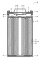
- FIG. 1 is a diagram schematically showing an axial cross section of a nonaqueous electrolyte secondary battery (cylindrical battery) that is an example of an embodiment.
- 1 is a diagram schematically showing a particle cross section of a positive electrode active material that is an example of an embodiment.
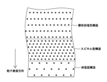
- FIG. 2 is a diagram schematically showing the crystal structure of a particle surface of a positive electrode active material and its vicinity as observed by a transmission electron microscope.
- the present inventors found that in the primary particles present on the surface of the secondary particles of the positive electrode active material (lithium transition metal composite oxide containing Ni), rock salt It has been found that cycle characteristics are specifically improved by forming a type structure, a spinel type structure, and a layered rock salt type structure. It is considered that the growth of the NiO phase was suppressed by generating the spinel structure as the lower layer of the NiO phase having the rock salt structure, and as a result, the capacity decrease due to charging and discharging was effectively suppressed.
- the positive electrode active material lithium transition metal composite oxide containing Ni
- non-aqueous electrolyte secondary battery a cylindrical battery in which a wound electrode body 14 is housed in a cylindrical outer can 16 with a bottom is exemplified.
- the non-aqueous electrolyte secondary battery according to the present disclosure may be, for example, a prismatic battery with a prismatic exterior can, a coin-shaped battery with a coin-shaped exterior can, and a laminate sheet containing a metal layer and a resin layer.
- a pouch-type battery may be provided with an exterior body made up of.
- the electrode body is not limited to a wound type electrode body, and may be a laminated type electrode body in which a plurality of positive electrodes and a plurality of negative electrodes are alternately laminated with separators interposed therebetween.
- FIG. 1 is a cross-sectional view of a nonaqueous electrolyte secondary battery 10 that is an example of an embodiment.
- the nonaqueous electrolyte secondary battery 10 includes a wound electrode body 14, a nonaqueous electrolyte (not shown), and an outer can 16 that houses the electrode body 14 and the nonaqueous electrolyte. Be prepared.
- the electrode body 14 includes a positive electrode 11 , a negative electrode 12 , and a separator 13 , and has a wound structure in which the positive electrode 11 and the negative electrode 12 are spirally wound with the separator 13 in between.
- the outer can 16 is a bottomed cylindrical metal container with an open end in the axial direction, and the opening of the outer can 16 is closed with a sealing member 17 .
- the sealing body 17 side of the battery will be referred to as the top
- the can bottom side of the outer can 16 will be referred to as the bottom.
- the non-aqueous electrolyte includes a non-aqueous solvent and an electrolyte salt dissolved in the non-aqueous solvent.
- the non-aqueous solvent for example, esters, ethers, nitriles, amides, mixed solvents of two or more of these, and the like are used.
- nonaqueous solvents include ethylene carbonate (EC), ethylmethyl carbonate (EMC), dimethyl carbonate (DMC), diethyl carbonate (DEC), and mixed solvents thereof.
- the non-aqueous solvent may contain a halogen-substituted product (for example, fluoroethylene carbonate) in which at least a portion of hydrogen in these solvents is replaced with a halogen atom such as fluorine.
- a lithium salt such as LiPF 6 is used as the electrolyte salt.
- vinylene carbonate (VC) may be added in an amount of 5% by mass or less based on the mass of the nonaqueous electrolyte.
- the positive electrode 11, the negative electrode 12, and the separator 13 that constitute the electrode body 14 are all long strip-shaped bodies, and are wound in a spiral shape so that they are alternately stacked in the radial direction of the electrode body 14.
- the negative electrode 12 is formed to be one size larger than the positive electrode 11 in order to prevent precipitation of lithium. That is, the negative electrode 12 is formed longer than the positive electrode 11 in the longitudinal direction and the width direction.
- the separators 13 are formed to be at least one size larger than the positive electrode 11, and for example, two separators 13 are arranged so as to sandwich the positive electrode 11 therebetween.
- the electrode body 14 has a positive electrode lead 20 connected to the positive electrode 11 by welding or the like, and a negative electrode lead 21 connected to the negative electrode 12 by welding or the like.
- Insulating plates 18 and 19 are arranged above and below the electrode body 14, respectively.
- the positive electrode lead 20 passes through the through hole of the insulating plate 18 and extends toward the sealing body 17, and the negative electrode lead 21 passes through the outside of the insulating plate 19 and extends toward the bottom of the outer can 16.
- the positive electrode lead 20 is connected by welding or the like to the lower surface of the internal terminal plate 23 of the sealing body 17, and the cap 27, which is the top plate of the sealing body 17 and electrically connected to the internal terminal plate 23, serves as a positive electrode terminal.
- the negative electrode lead 21 is connected to the bottom inner surface of the outer can 16 by welding or the like, and the outer can 16 serves as a negative electrode terminal.
- a gasket 28 is provided between the outer can 16 and the sealing body 17 to ensure airtightness inside the battery.
- the outer can 16 is formed with a grooved part 22 that supports the sealing body 17 and has a part of the side surface protruding inward.
- the grooved portion 22 is preferably formed in an annular shape along the circumferential direction of the outer can 16, and supports the sealing body 17 on its upper surface.
- the sealing body 17 is fixed to the upper part of the outer can 16 by the grooved part 22 and the open end of the outer can 16 which is crimped to the sealing body 17 .
- the sealing body 17 has a structure in which an internal terminal plate 23, a lower valve body 24, an insulating member 25, an upper valve body 26, and a cap 27 are laminated in order from the electrode body 14 side.
- Each member constituting the sealing body 17 has, for example, a disk shape or a ring shape, and each member except the insulating member 25 is electrically connected to each other.
- the lower valve body 24 and the upper valve body 26 are connected at their respective central portions, and an insulating member 25 is interposed between their respective peripheral portions.
- the positive electrode 11, negative electrode 12, and separator 13 that make up the electrode body 14 will be explained in detail, particularly the positive electrode active material that makes up the positive electrode 11.
- the positive electrode 11 includes a positive electrode core and a positive electrode composite material layer provided on the surface of the positive electrode core.
- a metal foil such as aluminum that is stable in the potential range of the positive electrode 11, a film with the metal disposed on the surface, or the like can be used.
- the positive electrode composite material layer includes a positive electrode active material, a binding material, and a conductive material, and is preferably provided on both surfaces of the positive electrode core except for the portion to which the positive electrode lead 20 is connected.
- the positive electrode 11 is made by, for example, applying a positive electrode composite slurry containing a positive electrode active material, a binding material, a conductive material, etc. to the surface of a positive electrode core, drying the coating film, and then compressing it to form a positive electrode composite material layer. It can be produced by forming it on both sides of the positive electrode core.
- Examples of the conductive material included in the positive electrode composite layer include carbon black such as acetylene black and Ketjen black, graphite, carbon nanotubes (CNT), carbon nanofibers, and graphene.
- Examples of the binder included in the positive electrode composite layer include fluororesins such as polytetrafluoroethylene (PTFE) and polyvinylidene fluoride (PVDF), polyacrylonitrile (PAN), polyimide, acrylic resin, and polyolefin. Furthermore, these resins may be used in combination with carboxymethyl cellulose (CMC) or a salt thereof, polyethylene oxide (PEO), or the like.
- the positive electrode 11 contains a lithium transition metal oxide containing at least Ni.
- the lithium transition metal composite oxide will be referred to as a "composite oxide (Z)."
- the composite oxide (Z) functions as a positive electrode active material.
- the positive electrode active material may have a composite oxide (Z) as a main component, and may be substantially composed only of the composite oxide (Z). Note that the positive electrode active material may contain a complex oxide other than the complex oxide (Z) or other compounds as long as the purpose of the present disclosure is not impaired.
- the composite oxide (Z) contains 80 mol% or more of Ni based on the total number of moles of metal elements excluding Li. By setting the Ni content to 80 mol% or more, a battery with high energy density can be obtained.
- the Ni content may be 85 mol% or more, or 90 mol% or more based on the total number of moles of metal elements excluding Li.
- the upper limit of the Ni content is, for example, 95 mol%.
- the composite oxide (Z) further contains at least one selected from Mn and Co.
- suitable composite oxides (Z) include lithium transition metal composite oxides containing Ni, Co, and Al, lithium transition metal composite oxides containing Ni, Co, and Mn, and lithium transition metal composite oxides containing Ni and Mn. Examples include lithium transition metal composite oxides.
- the composite oxide (Z) contains Co the content of Co is preferably 2 to 7 mol% with respect to the total number of moles of metal elements excluding Li. In this case, it is easy to realize a battery with high capacity and excellent cycle characteristics while reducing material costs.
- the content of Mn is preferably 2 to 15 mol% based on the total number of moles of metal elements excluding Li.
- the Mn content is, for example, 2 to 10 mol%. In this case, battery performance such as capacity and cycle characteristics can be improved more effectively.
- the composite oxide (Z) contains Al the content of Al is preferably 1 to 5 mol % based on the total number of moles of metal elements excluding Li. In this case, it is possible to increase the stability of the crystal structure while ensuring high capacity, and it is possible to improve cycle characteristics more effectively.
- the composite oxide (Z) further contains at least one selected from Ca and Sr.
- the composite oxide (Z) contains at least one selected from Ca and Sr, the effect of improving cycle characteristics becomes more significant.
- the content of Ca and Sr is, for example, 1 mol% or less based on the total number of moles of metal elements excluding Li.
- the composite oxide (Z) contains Ca and Sr, it is preferable that their total content is 1 mol% or less. In this case, cycle characteristics can be effectively improved without causing problems such as an increase in resistance or a decrease in capacity.
- the lower limit of their content is preferably 0.05 mol%.
- the total content of Ca and Sr is preferably 0.05 to 1 mol%, more preferably 0.1 to 0.5 mol%, based on the total number of moles of metal elements excluding Li.
- At least one selected from Ca and Sr is present at the interface between the primary particles, for example, at least inside the secondary particles of the composite oxide (Z).
- the effect of suppressing side reactions is considered to be significant, and the cycle characteristics can be effectively improved.
- Ca and Sr present at the interface of the primary particles can be confirmed by TEM-EDX and STEM-EDX.
- At least one selected from Ca and Sr exists, for example, in a uniformly dispersed state at the interface between each primary particle. Note that these may be attached to the surface of the secondary particles.
- the composite oxide (Z) may contain elements other than Li, Ni, Mn, Co, Al, Ca, and Sr. Examples of such elements include Nb, Zr, Ti, W, Si, B, Mg, Fe, Cu, Na, K, Ba, Mo, and the like.
- the content of elements constituting the composite oxide (Z) is measured using an inductively coupled plasma emission spectrometer (ICP-AES), an electron beam microanalyzer (EPMA), an energy dispersive X-ray analyzer (EDX), etc. can do.
- ICP-AES inductively coupled plasma emission spectrometer
- EPMA electron beam microanalyzer
- EDX energy dispersive X-ray analyzer
- FIG. 2 is a diagram schematically showing a particle cross section of the composite oxide (Z).
- the composite oxide (Z) is secondary particles 30 formed by agglomerating a plurality of primary particles 31.
- the volume-based median diameter (D50) of the composite oxide (Z) is, for example, 3 ⁇ m to 30 ⁇ m, preferably 5 ⁇ m to 25 ⁇ m. Since the composite oxide (Z) is the secondary particles 30 formed by agglomerating the primary particles 31, the D50 of the composite oxide means the D50 of the secondary particles 30.
- D50 means the particle size at which the cumulative frequency is 50% from the smallest particle size in the volume-based particle size distribution, and is also called the median diameter.
- the particle size distribution of the composite oxide (Z) can be measured using a laser diffraction type particle size distribution measuring device (for example, MT3000II manufactured by Microtrac Bell Co., Ltd.) using water as a dispersion medium.
- the average particle size of the primary particles 31 is, for example, 0.05 ⁇ m to 1 ⁇ m.
- the average particle diameter of the primary particles 31 is calculated by averaging the diameters of circumscribed circles of the primary particles 31 extracted by analyzing a scanning electron microscope (SEM) image of a cross section of the secondary particles 30.
- Predetermined voids may exist inside the secondary particles 30.
- the void exists, for example, at the interface between the primary particles 31.
- the average porosity of the secondary particles 30 is, for example, 0.1 to 5%.
- the porosity of the secondary particles 30 is the ratio of the area of voids to the cross section of the secondary particles, and is calculated by the formula: (area of voids/cross-sectional area of secondary particles) ⁇ 100.
- the porosity of the secondary particles 30 is determined by analyzing the SEM image of the cross section of the secondary particles. Extraction of the primary particles 31 and void areas is performed by appropriately selecting image analysis software such as Image J or Avizo-Materials Science. The SEM image is subjected to noise removal using a non-local means filter, BM3D, etc., and the primary particles 31 and void regions are extracted by applying edge detection and the Marker-Based-Watershed method with a brightness threshold superimposed. Note that the area detected by Watershed centered around the high brightness value area is defined as a primary particle, and the low brightness area is defined as a void.
- FIG. 3 is a diagram schematically showing the crystal structure of the composite oxide (Z) particle surface and its vicinity (region indicated by X in FIG. 2) observed by a transmission electron microscope (TEM, STEM). .
- the crystal structure in a micro region of the composite oxide (Z) can be analyzed by nanobeam electron diffraction using a TEM.
- FIG. 3 schematically shows an electron diffraction pattern of a nanobeam near the surface of a primary particle 31 existing on the surface of a secondary particle 30.
- the primary particles 31 present on the surface of the secondary particles 30 contain three types of crystal phases.
- the primary particles 31 present on the surface of the secondary particles 30 have a crystal structure including a rock salt type structure, a spinel type structure, and a layered rock salt type structure formed in order from the particle surface. That is, in a predetermined depth range from the surface of the primary particles 31 (hereinafter sometimes referred to as "surface layer"), a three-phase structure with mutually different crystal structures is formed.
- the three-phase structure may be formed not only in the surface layer of the primary particles 31 present on the surface of the secondary particles 30 but also in the surface layer of the primary particles 31 in contact with the internal voids of the secondary particles 30.
- the crystal structure of the composite oxide (Z) is, for example, a layered rock salt structure in most parts except for the surface layer of the primary particles 31 present on the surface of the secondary particles 30 and the surface layer of the primary particles 31 in contact with internal voids.
- the layered rock salt structure is a layered crystal structure in which transition metal ions and Li ions are arranged alternately, and belongs to the space group R-3m. Li ions can move smoothly within the layered rock salt structure.
- the rock salt type structure and the spinel type structure are present only in the surface layer of the primary particle 31 existing on the surface of the secondary particle 30 and in the surface layer of the primary particle 31 in contact with the internal voids of the secondary particle 30. It is formed.
- the rock salt type structure is considered to be a crystalline phase derived from the NiO phase generated on the particle surface layer, and belongs to the space group Fm-3m.
- the rock salt structure inhibits the diffusion of Li ions.
- Spinel-type structures belong to space group Fd-3m.
- the average thickness of the rock salt type structure is preferably 5 nm or less, more preferably 4 nm or less, and particularly preferably 3 nm or less. If the average thickness of the rock salt type structure is within this range, the effect of improving cycle characteristics will be more significant.
- the average thickness of the rock salt type structure is the average value of the shortest distance from any position on the particle surface to the interface with the spinel type structure in the cross section of the primary particle 31, and is the average value of the shortest distance from an arbitrary position on the particle surface to the interface with the spinel type structure. It can be analyzed by Although the lower limit of the average thickness of the rock salt type structure is not particularly limited, one example is 0.5 nm.
- the rock salt type structure is formed only within a thickness range of 5 nm, particularly preferably 3 nm, from the surface of the specific primary particle 31.
- the formation of the rock salt type structure in a limited manner in this range is considered to be due to the effect of the spinel type structure existing inside the particle rather than the rock salt type structure.
- the rock salt-type structure is formed before charging and discharging the battery.
- the average thickness of the spinel structure is preferably 7 nm or less, more preferably 6 nm or less, and particularly preferably 5 nm or less. If the average thickness of the spinel structure is within this range, the effect of improving cycle characteristics will be more significant.
- the average thickness of the spinel structure is the average value of the shortest distance from the interface with the rock salt structure to the interface with the layered rock salt structure in the cross section of the primary particle 31, and is the average value of the shortest distance from the interface with the rock salt structure to the interface with the layered rock salt structure. It can be analyzed using the method. Although the lower limit of the average thickness of the spinel structure is not particularly limited, one example is 1.5 nm.
- the spinel-type structure does not exist before charging and discharging the battery, but is formed after charging and discharging the battery.
- the average thickness of the spinel structure is, for example, a value after a cycle test described below. That is, the three-phase structure of a rock salt type structure, a spinel type structure, and a layered rock salt type structure is generated as the battery is charged and discharged, and after a charge/discharge cycle similar to the cycle test described below, a spinel type structure with the above thickness is formed. is formed.
- a composite oxide (Z) in which a spinel structure is generated after charging and discharging and a composite oxide in which a spinel structure is not generated.
- the composite oxide (Z) is produced by mixing and firing a transition metal oxide containing Ni, Mn, Co, Al, etc., a Ca raw material, a Sr raw material, and a Li raw material such as lithium hydroxide (LiOH), for example. It can be synthesized by After pulverizing the fired product, the composite oxide (Z) is obtained by washing with water.
- Ca raw materials include Ca(OH) 2 , CaO, CaCO 3 , CaSO 4 , Ca(NO 3 ) 2 and the like.
- Sr raw materials include Sr(OH) 2 , Sr(OH) 2.H2O , Sr (OH) 2.8H2O , SrO, SrCO3 , SrSO4 , Sr( NO3 ) 2, etc. It will be done.
- the molar ratio of the metal element (Me) in the composite oxide to Li in the Li raw material (Li/Me ratio) and the firing conditions are particularly important in forming the above three types of crystal phases on the surface layer of the primary particles 31. It is an important factor and needs to be strictly controlled.
- a suitable Li/Me ratio varies somewhat depending on the composition of the mixture, but is, for example, 1.015 to 1.055. For example, if the Li/Me ratio is too low, such as 1.000, mixing increases and spinel-type structures are not formed. On the other hand, if the Li/Me ratio is too high, such as 1.060, crystal growth progresses too much and rapid rock salt formation progresses, and no spinel structure is formed.
- the step of firing the mixture includes, for example, a first firing step and a second firing step at a higher temperature than the first firing step. Further, the mixture is fired in an oxygen atmosphere, and it is preferable to set the oxygen concentration to 85% or more. For example, if the oxygen concentration is too low, such as 80% or less, oxygen defects will increase and a spinel structure will not be formed.
- a suitable first firing temperature varies somewhat depending on the composition of the mixture, but is, for example, 600 to 680°C.
- a suitable second firing temperature is, for example, 700 to 780°C. If the firing temperature is too high, crystal growth progresses too much and rapid formation of a rock salt structure occurs, preventing the formation of a spinel-type structure.
- the firing step is performed by charging the above mixture into a firing furnace.
- the first temperature increase rate from room temperature to the first firing temperature is preferably 2 to 4° C./min. Further, it is preferable that the temperature increase rate from the first firing temperature to the second firing temperature is slower than the first temperature increase rate. If the temperature increase rate is too fast, oxygen defects, distortions in the structure, etc. remain, and a spinel structure is not formed.
- the negative electrode 12 includes a negative electrode core and a negative electrode composite material layer provided on the surface of the negative electrode core.
- a foil of a metal such as copper that is stable in the potential range of the negative electrode 12, a film with the metal disposed on the surface, or the like can be used.
- the negative electrode composite material layer contains a negative electrode active material and a binding material, and is preferably provided on both sides of the negative electrode core except for the portion to which the negative electrode lead 21 is connected.
- the negative electrode 12 is prepared by applying a negative electrode composite slurry containing a negative electrode active material, a binder, etc. to the surface of a negative electrode core, drying the coating film, and then compressing the negative electrode composite material layer to the negative electrode core. It can be produced by forming it on both sides of.
- the negative electrode composite material layer generally includes a carbon material that reversibly occludes and releases lithium ions as a negative electrode active material.
- a carbon material that reversibly occludes and releases lithium ions as a negative electrode active material.
- the carbon material include natural graphite such as flaky graphite, lumpy graphite, and earthy graphite, and graphite such as artificial graphite such as massive artificial graphite (MAG) and graphitized mesophase carbon microbeads (MCMB).
- MAG massive artificial graphite
- MCMB graphitized mesophase carbon microbeads
- an active material containing at least one of an element that alloys with Li, such as Si and Sn, and a material containing the element may be used.
- a suitable example of the active material is a SiO 2 phase, a silicate phase such as lithium silicate, or a Si-containing material in which Si fine particles are dispersed in an amorphous carbon phase.
- Graphite and a Si-containing material may be used together as the negative electrode active material.
- the binder included in the negative electrode composite layer fluororesin, PAN, polyimide, acrylic resin, polyolefin, etc. can be used as the binder included in the negative electrode composite layer, but styrene-butadiene rubber (SBR) can be used. is preferred.
- the negative electrode composite material layer further contains CMC or a salt thereof, polyacrylic acid (PAA) or a salt thereof, polyvinyl alcohol (PVA), or the like.
- PAA polyacrylic acid
- PVA polyvinyl alcohol
- a porous sheet having ion permeability and insulation properties is used.
- porous sheets include microporous thin films, woven fabrics, and nonwoven fabrics.
- Suitable materials for the separator 13 include polyolefins such as polyethylene and polypropylene, cellulose, and the like.
- the separator 13 may have a single layer structure or a multilayer structure. Further, a resin layer with high heat resistance such as aramid resin may be formed on the surface of the separator 13.
- a filler layer containing an inorganic filler may be formed at the interface between the separator 13 and at least one of the positive electrode 11 and the negative electrode 12.
- the inorganic filler include oxides and phosphoric acid compounds containing metal elements such as Ti, Al, Si, and Mg.
- the filler layer can be formed by applying a slurry containing the filler to the surface of the positive electrode 11, the negative electrode 12, or the separator 13.
- Example A1> [Synthesis of lithium transition metal composite oxide (positive electrode active material)] A composite oxide containing Ni, Co, and Al and lithium hydroxide are prepared such that the molar ratio of the metal element (Me) in the composite oxide to Li in the lithium hydroxide (Li/Me ratio) is 1:1. 020. This mixture was put into a firing furnace and fired in two stages. In the firing process, the heating rate was 3°C/min (hereinafter referred to as "first heating rate”) under an oxygen stream with an oxygen concentration of 95% (flow rate of 2 mL/min per 10 cm3 and 5 L/min per 1 kg of mixture). ), and the temperature was raised from room temperature to 650°C (hereinafter referred to as "first firing temperature”).
- the temperature was raised from 650°C to 750°C (hereinafter referred to as the ⁇ second firing temperature'') at a temperature increase rate of 1°C/min (hereinafter referred to as the ⁇ second temperature increase rate''). It was kept at °C for 3 hours. After pulverizing the fired product, it was washed with water to obtain a lithium transition metal composite oxide (positive electrode active material).
- the composition of the composite oxide was Li 0.99 Ni 0.90 Co 0.05 Al 0.05 O 2 . Further, from the SEM image of the lithium transition metal composite oxide, it was confirmed that the composite oxide was secondary particles formed by agglomeration of primary particles.
- the above lithium transition metal composite oxide was used as the positive electrode active material.
- a positive electrode active material, acetylene black, and polyvinylidene fluoride (PVdF) were mixed at a solid content mass ratio of 95:3:2, and a positive electrode composite was prepared using N-methyl-2-pyrrolidone (NMP) as a dispersion medium.
- NMP N-methyl-2-pyrrolidone
- a slurry was prepared.
- the positive electrode composite slurry is applied to both sides of a positive electrode core made of aluminum foil, the coating film is dried, and then the coating film is rolled using a roller and cut into a predetermined electrode size to form the positive electrode core.
- a positive electrode having positive electrode composite material layers formed on both sides was obtained. Note that an exposed portion in which the surface of the positive electrode core was exposed was provided in a part of the positive electrode.
- Natural graphite was used as the negative electrode active material.
- a dispersion of negative electrode active material, sodium carboxymethyl cellulose (CMC-Na), and styrene-butadiene rubber (SBR) was mixed at a solid content mass ratio of 100:1:1, and negative electrode synthesis was performed using water as a dispersion medium.
- a material slurry was prepared.
- the negative electrode composite slurry is applied to both sides of a negative electrode core made of copper foil, the coating is dried, and then the coating is rolled using a roller and cut into a predetermined electrode size to form the negative electrode core.
- a negative electrode was obtained in which negative electrode composite layers were formed on both sides. Note that an exposed portion in which the surface of the negative electrode core was exposed was provided in a part of the negative electrode.
- Non-aqueous electrolyte 1.2 mol of LiPF 6 was added to a mixed solvent of ethylene carbonate (EC), methyl ethyl carbonate (MEC), and dimethyl carbonate (DMC) mixed at a volume ratio of 3:3:4 (25°C).
- EC ethylene carbonate
- MEC methyl ethyl carbonate
- DMC dimethyl carbonate
- a non-aqueous electrolyte solution was prepared by dissolving the solution at a concentration of 1/liter.
- test cell non-aqueous electrolyte secondary battery
- An aluminum lead was attached to the exposed portion of the positive electrode, and a nickel lead was attached to the exposed portion of the negative electrode, and the positive and negative electrodes were spirally wound through a polyolefin separator to produce a wound electrode body.
- This electrode body was housed in a cylindrical outer can with a bottom, and after the non-aqueous electrolyte was injected, the opening of the outer can was closed with a sealing body to obtain a test cell.
- Example A2> A lithium transition metal composite oxide was synthesized in the same manner as in Example A1, except that the second firing temperature was changed to 730° C., and a test cell was produced using the composite oxide as the positive electrode active material.
- Example A3> A lithium transition metal composite oxide was synthesized in the same manner as in Example A1, except that calcium hydroxide was further added as a raw material for the lithium transition metal composite oxide, and the composite oxide was used as the positive electrode active material for testing. A cell was created. ICP-AES confirmed that the composition of the positive electrode active material was Li 0.99 Ni 0.887 Co 0.04 Al 0.05 Ca 0.023 O 2 .
- Example A4> A lithium transition metal composite oxide was synthesized in the same manner as in Example A1, except that strontium hydroxide was further added as a raw material for the lithium transition metal composite oxide, and the composite oxide was used as the positive electrode active material for testing. A cell was created. ICP-AES confirmed that the composition of the positive electrode active material was Li 0.99 Ni 0.899 Co 0.05 Al 0.05 Sr 0.01 O 2 .
- Example A5> A lithium-transition metal composite oxide was synthesized in the same manner as in Example A1, except that calcium hydroxide and strontium hydroxide were further added as raw materials for the lithium-transition metal composite oxide, and the composite oxide was added to the positive electrode active material.
- a test cell was prepared using ICP-AES confirmed that the composition of the positive electrode active material was Li 0.99 Ni 0.877 Co 0.05 Al 0.04 Ca 0.023 Sr 0.01 O 2 .
- Example A1 A lithium transition metal composite oxide was synthesized in the same manner as in Example A1, except that the first heating rate was changed to 5°C/min and the second heating rate was changed to 3°C/min, A test cell was prepared using the composite oxide as a positive electrode active material.
- Example A2 A lithium transition metal composite oxide was synthesized in the same manner as in Example A1, except that the oxygen concentration in the firing step was changed to 80%, and a test cell was produced using the composite oxide as the positive electrode active material.
- Example A3> A lithium transition metal composite oxide was synthesized in the same manner as in Example A1, except that the second firing temperature was changed to 800° C., and a test cell was produced using the composite oxide as the positive electrode active material.
- Example A5 A lithium-transition metal composite oxide was synthesized in the same manner as in Example A1, except that the Li/Me ratio was changed to 1.060 and the second firing temperature was changed to 800°C. A test cell was prepared using the composite oxide.
- Example B1> [Synthesis of lithium transition metal composite oxide (positive electrode active material)] A composite oxide containing Ni, Co, and Mn and lithium hydroxide are prepared such that the molar ratio of the metal element (Me) in the composite oxide to Li in the lithium hydroxide (Li/Me ratio) is 1:1. 050. This mixture was put into a firing furnace and fired in two stages. In the firing process, under an oxygen stream with an oxygen concentration of 95% (flow rate of 2 mL/min per 10 cm3 and 5 L/min per 1 kg of mixture), the first heating temperature was 3 °C/min, and the temperature was increased from room temperature to 630 °C (first The temperature was raised to (firing temperature).
- the temperature was raised from 630°C to 770°C (second firing temperature) at a second temperature increase rate of 1°C/min, and held at 770°C for 5 hours. After pulverizing the fired product, it was washed with water to obtain a lithium transition metal composite oxide (positive electrode active material).
- the composition of the composite oxide was Li 0.99 Ni 0.90 Co 0.05 Mn 0.05 O 2 . Further, from the SEM image of the lithium transition metal composite oxide, it was confirmed that the composite oxide was secondary particles formed by agglomeration of primary particles.
- Example B2> A lithium transition metal composite oxide was synthesized in the same manner as in Example B1, except that the Li/Me ratio was changed to 1.030 and the holding time of the second firing temperature was changed to 8 hours, A test cell was prepared using the composite oxide as a positive electrode active material.
- Example B3> A lithium-transition metal composite oxide was synthesized in the same manner as in Example B1, except that calcium hydroxide was further added as a raw material for the lithium-transition metal composite oxide, and the composite oxide was used as the positive electrode active material for testing. A cell was created. ICP-AES confirmed that the composition of the positive electrode active material was Li 0.99 Ni 0.89 Co 0.05 Mn 0.04 Ca 0.02 O 2 .
- Example B4> A lithium-transition metal composite oxide was synthesized in the same manner as in Example B1, except that calcium hydroxide and strontium hydroxide were further added as raw materials for the lithium-transition metal composite oxide, and the composite oxide was added to the positive electrode active material.
- a test cell was prepared using ICP-AES confirmed that the composition of the positive electrode active material was Li 0.99 Ni 0.885 Co 0.04 Mn 0.04 Ca 0.03 Sr 0.005 O 2 .
- Example B1 except that the first temperature increase rate was changed to 5°C/min, the second temperature increase rate was changed to 3°C/min, and the second firing temperature was changed to 750°C.
- a lithium transition metal composite oxide was synthesized in the same manner as described above, and a test cell was produced using the composite oxide as a positive electrode active material.
- Example C1> [Synthesis of lithium transition metal composite oxide (positive electrode active material)] A composite oxide containing Ni and Mn and lithium hydroxide are prepared such that the molar ratio of the metal element (Me) in the composite oxide to Li in the lithium hydroxide (Li/Me ratio) is 1:1.030. Mixed so that This mixture was put into a firing furnace and fired in two stages. In the firing process, under an oxygen stream with an oxygen concentration of 95% (flow rate of 2 mL/min per 10 cm3 and 5 L/min per 1 kg of mixture), the first heating temperature was 2 °C/min, and the temperature was increased from room temperature to 650 °C (first The temperature was raised to (firing temperature).
- the temperature was raised from 650°C to 730°C (second firing temperature) at a second temperature increase rate of 1°C/min, and held at 730°C for 5 hours. After pulverizing the fired product, it was washed with water to obtain a lithium transition metal composite oxide (positive electrode active material).
- the composition of the composite oxide was Li 0.99 Ni 0.90 Mn 0.10 O 2 . Further, from the SEM image of the lithium transition metal composite oxide, it was confirmed that the composite oxide was secondary particles formed by agglomeration of primary particles.
- Example C2> A lithium transition metal composite oxide was synthesized in the same manner as in Example C1, except that aluminum hydroxide was further added as a raw material for the lithium transition metal composite oxide, and the composite oxide was used as the positive electrode active material for testing. A cell was created. ICP-AES confirmed that the composition of the positive electrode active material was Li 0.99 Ni 0.91 Mn 0.04 Al 0.05 O 2 .
- Example C3> A lithium-transition metal composite oxide was synthesized in the same manner as in Example C1, except that calcium hydroxide was further added as a raw material for the lithium-transition metal composite oxide, and the composite oxide was used as the positive electrode active material for testing. A cell was created. ICP-AES confirmed that the composition of the positive electrode active material was Li 0.99 Ni 0.88 Mn 0.09 Ca 0.03 O 2 .
- Example C4 A lithium transition metal composite oxide was synthesized in the same manner as in Example C1, except that calcium hydroxide and strontium hydroxide were further added as raw materials for the lithium transition metal composite oxide, and the composite oxide was added to the positive electrode active material.
- a test cell was prepared using ICP-AES confirmed that the composition of the positive electrode active material was Li 0.99 Ni 0.87 Mn 0.10 Ca 0.02 Sr 0.01 O 2 .
- Example C5 A lithium transition metal composite oxide was synthesized in the same manner as in Example C1, except that aluminum hydroxide, calcium hydroxide, and strontium hydroxide were further added as raw materials for the lithium transition metal composite oxide, and a positive electrode active material A test cell was prepared using the composite oxide. ICP-AES confirmed that the composition of the positive electrode active material was Li 0.99 Ni 0.89 Mn 0.03 Al 0.05 Ca 0.02 Sr 0.01 O 2 .
- Example C1 except that the first heating rate was changed to 5°C/min, the second heating rate was changed to 3°C/min, and the second firing temperature was changed to 750°C.
- a lithium transition metal composite oxide was synthesized in the same manner as described above, and a test cell was produced using the composite oxide as a positive electrode active material.
- Example C2 except that the first heating rate was changed to 5°C/min, the second heating rate was changed to 3°C/min, and the second firing temperature was changed to 750°C.
- a lithium transition metal composite oxide was synthesized in the same manner as described above, and a test cell was produced using the composite oxide as a positive electrode active material.
- Example D1> [Synthesis of lithium transition metal composite oxide (positive electrode active material)] A composite oxide containing Ni and Mn and lithium hydroxide are prepared such that the molar ratio of the metal element (Me) in the composite oxide to Li in the lithium hydroxide (Li/Me ratio) is 1:1.050. Mixed so that This mixture was put into a firing furnace and fired in two stages. In the firing process, under an oxygen flow with an oxygen concentration of 95% (flow rate of 2 mL/min per 10 cm3 and 5 L/min per 1 kg of mixture), the first heating temperature was 2 °C/min, and the temperature was increased from room temperature to 670 °C (first The temperature was raised to (firing temperature).
- the temperature was raised from 670°C to 760°C (second firing temperature) at a second temperature increase rate of 1°C/min, and held at 760°C for 5 hours. After pulverizing the fired product, it was washed with water to obtain a lithium transition metal composite oxide (positive electrode active material).
- the composition of the composite oxide was Li 0.99 Ni 0.81 Mn 0.19 O 2 . Further, from the SEM image of the lithium transition metal composite oxide, it was confirmed that the composite oxide was secondary particles formed by agglomeration of primary particles.
- Example D2> A lithium-transition metal composite oxide was synthesized in the same manner as in Example D1, except that calcium hydroxide was further added as a raw material for the lithium-transition metal composite oxide, and a test cell was prepared using the composite oxide as the positive electrode active material. was created. ICP-AES confirmed that the composition of the positive electrode active material was Li 0.99 Ni 0.80 Mn 0.18 Ca 0.02 O 2 .
- Example D3> A lithium-transition metal composite oxide was synthesized in the same manner as in Example D1, except that calcium hydroxide and strontium hydroxide were further added as raw materials for the lithium-transition metal composite oxide, and the composite oxide was added to the positive electrode active material.
- a test cell was prepared using ICP-AES confirmed that the composition of the positive electrode active material was Li 0.99 Ni 0.80 Mn 0.17 Ca 0.02 Sr 0.01 O 2 .
- Example D1 except that the first heating rate was changed to 5°C/min, the second heating rate was changed to 3°C/min, and the second firing temperature was changed to 800°C.
- a lithium transition metal composite oxide was synthesized in the same manner as described above, and a test cell was produced using the composite oxide as a positive electrode active material.
- a cycle test was conducted for each of the test cells of the above examples and comparative examples, and the capacity retention rate after the test was evaluated.
- the evaluation results are shown in Tables 1 to 4 along with the physical properties of the positive electrode active materials.
- the capacity retention rates shown in each table are relative values when the capacity retention rate of the test cell of Comparative Example 1 in each table is set to 100.
- nanobeam electron diffraction using TEM we analyzed the crystal structure of the surface layer of the primary particles present on the surface of the secondary particles of the positive electrode active material in the cycle test, and found that the rock salt-type structure (NiO phase) and the spinel-type structure The average thickness was measured.
- Configuration 1 Contains a lithium transition metal composite oxide containing at least Ni, The lithium transition metal composite oxide is a secondary particle formed by agglomeration of primary particles, and the primary particles present on the surface of the secondary particle have a rock salt type structure formed in order from the particle surface.
- a positive electrode active material for a nonaqueous electrolyte secondary battery which has a crystal structure including a spinel structure, and a layered rock salt structure.
- Configuration 2 The positive electrode active material for a nonaqueous electrolyte secondary battery according to Configuration 1, wherein the spinel structure has an average thickness of 5 nm or less.
- Configuration 3 The positive electrode active material for a non-aqueous electrolyte secondary battery according to configuration 1 or 2, wherein the average thickness of the rock salt type structure is 3 nm or less.
- Configuration 4 The positive electrode active material for a non-aqueous electrolyte secondary battery according to any one of configurations 1 to 3, wherein the lithium transition metal composite oxide contains at least one selected from Ca and Sr.
- Configuration 5 In the lithium transition metal composite oxide, the non-aqueous electrolyte diode according to any one of configurations 1 to 4 has a Ni content of 80 mol% or more based on the total number of moles of metal elements excluding Li. Cathode active material for next-generation batteries.
- Configuration 6 A nonaqueous electrolyte secondary battery comprising a positive electrode containing the positive electrode active material according to any one of configurations 1 to 5, a negative electrode, and a nonaqueous electrolyte.
- Non-aqueous electrolyte secondary battery 11 positive electrode, 12 negative electrode, 13 separator, 14 electrode body, 16 outer can, 17 sealing body, 18, 19 insulating plate, 20 positive electrode lead, 21 negative electrode lead, 22 grooved part, 23 internal terminal Plate, 24 lower valve body, 25 insulating member, 26 upper valve body, 27 cap, 28 gasket
Abstract
実施形態の一例である非水電解質二次電池は、正極活物質を含む正極と、負極と、非水電解質とを備える。正極活物質は、少なくともNiを含有するリチウム遷移金属複合酸化物を含む。リチウム遷移金属複合酸化物は、一次粒子が凝集して形成された二次粒子であって、二次粒子の表面に存在する一次粒子は、粒子表面から順に形成された、岩塩型構造、スピネル型構造、および層状岩塩型構造を含む結晶構造を有する。
Description
本開示は、非水電解質二次電池用正極活物質および当該正極活物質を用いた非水電解質二次電池に関する。
近年、Ni含有量の多いリチウム遷移金属複合酸化物が、高エネルギー密度の正極活物質として注目されている。しかし、Ni含有量の多いリチウム遷移金属複合酸化物は、複合酸化物粒子の表面構造が不安定化し易く、長期の充放電サイクル時に容量低下が大きくなるという課題がある。
かかる状況に鑑みて、特許文献1では、組成式LiNixMnyCozO2で表される正極活物質であって、空間群R-3mの層状岩塩型構造を有するコア粒子と、コア粒子を被覆するスピネル型構造を有する被覆層とを含む正極活物質が提案されている。特許文献1には、この正極活物質を用いることにより、正極活物質の容量低下や伝導抵抗の上昇を抑制できる、との効果が記載されている。
上述のように、非水電解質二次電池の正極活物質としてNi含有量の多いリチウム遷移金属複合酸化物を用いた場合に、充放電に伴う容量低下を抑制して、サイクル特性(耐久性)を向上させることは重要な課題である。なお、本発明者らの検討の結果、特許文献1の正極活物質を用いた場合、電池の初期容量が低くなることが分かった。即ち、Ni含有量の多いリチウム遷移金属複合酸化物は高エネルギー密度であることが期待されるが、特許文献1の正極活物質では、その効果が失われることになる。
本開示に係る非水電解質二次電池用正極活物質は、少なくともNiを含有するリチウム遷移金属複合酸化物を含み、リチウム遷移金属複合酸化物は、一次粒子が凝集して形成された二次粒子であって、二次粒子の表面に存在する一次粒子は、粒子表面から順に形成された、岩塩型構造、スピネル型構造、および層状岩塩型構造を含む結晶構造を有する。
本開示に係る非水電解質二次電池は、上記正極活物質を含む正極と、負極と、非水電解質とを備える。
本開示に係る正極活物質は、Ni含有量の多い高エネルギー密度の正極活物質であって、非水電解質二次電池の充放電に伴う容量低下を抑制し、サイクル特性を向上させる。本開示に係る正極活物質を用いた非水電解質二次電池は、例えば、エネルギー密度が高く、サイクル特性に優れる。
上述の通り、正極活物質としてNi含有量の多いリチウム遷移金属複合酸化物を用いた場合、長期の充放電サイクル時に容量低下が大きくなるという課題がある。これは、充放電に伴って正極活物質の粒子表面構造が不安定化し、粒子表面の結晶構造が岩塩型構造のNiO相に変位して成長することが大きな要因であると考えられる。そして、NiO相によりLiイオンの拡散が阻害される結果、抵抗が上昇して容量が低下する。
本発明者らは上記課題を解決すべく鋭意検討した結果、正極活物質(Niを含有するリチウム遷移金属複合酸化物)の二次粒子の表面に存在する一次粒子において、粒子表面から順に、岩塩型構造、スピネル型構造、および層状岩塩型構造を形成することで、サイクル特性が特異的に向上することを見出した。岩塩型構造のNiO相の下層としてスピネル型構造を生成させることでNiO相の成長が抑制され、その結果、充放電に伴う容量低下が効果的に抑制されたと考えられる。
なお、高エネルギー密度と良好なサイクル特性を両立させるためには、二次粒子の表面に存在する一次粒子の表層として、岩塩型構造とスピネル型構造の積層構造が必要不可欠であると考えられる。
以下、図面を参照しながら、本開示に係る正極活物質および当該正極活物質を用いた非水電解質二次電池の実施形態の一例について詳細に説明する。なお、以下で説明する複数の実施形態、変形例の各構成要素を選択的に組み合わせてなる構成は本開示の範囲に含まれている。
以下では、非水電解質二次電池として、巻回型の電極体14が有底円筒形状の外装缶16に収容された円筒形電池を例示するが、電池の外装体は円筒形の外装缶に限定されない。本開示に係る非水電解質二次電池は、例えば、角形の外装缶を備えた角形電池、コイン形の外装缶を備えたコイン形電池であってもよく、金属層および樹脂層を含むラミネートシートで構成された外装体を備えたパウチ型電池であってもよい。また、電極体は巻回型に限定されず、複数の正極と複数の負極がセパレータを介して交互に積層された積層型の電極体であってもよい。
図1は、実施形態の一例である非水電解質二次電池10の断面図である。図1に示すように、非水電解質二次電池10は、巻回型の電極体14と、非水電解質(図示せず)と、電極体14および非水電解質を収容する外装缶16とを備える。電極体14は、正極11、負極12、およびセパレータ13を有し、正極11と負極12がセパレータ13を介して渦巻き状に巻回された巻回構造を有する。外装缶16は、軸方向一端側が開口した有底円筒形状の金属製容器であって、外装缶16の開口部は封口体17によって塞がれている。以下では、説明の便宜上、電池の封口体17側を上、外装缶16の缶底側を下とする。
非水電解質は、非水溶媒と、非水溶媒に溶解した電解質塩とを含む。非水溶媒には、例えば、エステル類、エーテル類、ニトリル類、アミド類、およびこれらの2種以上の混合溶媒等が用いられる。非水溶媒の一例としては、エチレンカーボネート(EC)、エチルメチルカーボネート(EMC)、ジメチルカーボネート(DMC)、ジエチルカーボネート(DEC)、およびこれらの混合溶媒等が挙げられる。非水溶媒は、これら溶媒の水素の少なくとも一部をフッ素等のハロゲン原子で置換したハロゲン置換体(例えば、フルオロエチレンカーボネート等)を含有していてもよい。電解質塩には、例えば、LiPF6等のリチウム塩が使用される。また、非水電解質の質量に対して5質量%以下のビニレンカーボネート(VC)が添加されてもよい。
電極体14を構成する正極11、負極12、およびセパレータ13は、いずれも帯状の長尺体であって、渦巻状に巻回されることで電極体14の径方向に交互に積層される。負極12は、リチウムの析出を防止するために、正極11よりも一回り大きな寸法で形成される。即ち、負極12は、正極11よりも長手方向および幅方向に長く形成される。セパレータ13は、少なくとも正極11よりも一回り大きな寸法で形成され、例えば、正極11を挟むように2枚配置される。電極体14は、溶接等により正極11に接続された正極リード20と、溶接等により負極12に接続された負極リード21とを有する。
電極体14の上下には、絶縁板18,19がそれぞれ配置される。図1に示す例では、正極リード20が絶縁板18の貫通孔を通って封口体17側に延び、負極リード21が絶縁板19の外側を通って外装缶16の底部側に延びている。正極リード20は封口体17の内部端子板23の下面に溶接等で接続され、内部端子板23と電気的に接続された封口体17の天板であるキャップ27が正極端子となる。負極リード21は外装缶16の底部内面に溶接等で接続され、外装缶16が負極端子となる。
外装缶16と封口体17の間にはガスケット28が設けられ、電池内部の密閉性が確保される。外装缶16には、側面部の一部が内側に張り出した、封口体17を支持する溝入部22が形成されている。溝入部22は、外装缶16の周方向に沿って環状に形成されることが好ましく、その上面で封口体17を支持する。封口体17は、溝入部22と、封口体17に対して加締められた外装缶16の開口端部とにより、外装缶16の上部に固定される。
封口体17は、電極体14側から順に、内部端子板23、下弁体24、絶縁部材25、上弁体26、およびキャップ27が積層された構造を有する。封口体17を構成する各部材は、例えば円板形状又はリング形状を有し、絶縁部材25を除く各部材は互いに電気的に接続されている。下弁体24と上弁体26は各々の中央部で接続され、各々の周縁部の間には絶縁部材25が介在している。異常発熱で電池の内圧が上昇すると、下弁体24が上弁体26をキャップ27側に押し上げるように変形して破断することにより、下弁体24と上弁体26の間の電流経路が遮断される。さらに内圧が上昇すると、上弁体26が破断し、キャップ27の開口部からガスが排出される。
以下、電極体14を構成する正極11、負極12、セパレータ13について、特に正極11を構成する正極活物質について詳説する。
[正極]
正極11は、正極芯体と、正極芯体の表面に設けられた正極合材層とを有する。正極芯体には、アルミニウムなどの正極11の電位範囲で安定な金属の箔、当該金属を表面に配置したフィルム等を用いることができる。正極合材層は、正極活物質、結着材、および導電材を含み、正極リード20が接続される部分を除く正極芯体の両面に設けられることが好ましい。正極11は、例えば、正極活物質、結着材、および導電材等を含む正極合材スラリーを正極芯体の表面に塗布し、塗膜を乾燥させた後、圧縮して正極合材層を正極芯体の両面に形成することにより作製できる。
正極11は、正極芯体と、正極芯体の表面に設けられた正極合材層とを有する。正極芯体には、アルミニウムなどの正極11の電位範囲で安定な金属の箔、当該金属を表面に配置したフィルム等を用いることができる。正極合材層は、正極活物質、結着材、および導電材を含み、正極リード20が接続される部分を除く正極芯体の両面に設けられることが好ましい。正極11は、例えば、正極活物質、結着材、および導電材等を含む正極合材スラリーを正極芯体の表面に塗布し、塗膜を乾燥させた後、圧縮して正極合材層を正極芯体の両面に形成することにより作製できる。
正極合材層に含まれる導電材としては、アセチレンブラック、ケッチェンブラック等のカーボンブラック、黒鉛、カーボンナノチューブ(CNT)、カーボンナノファイバー、グラフェンなどの炭素材料が例示できる。正極合材層に含まれる結着材としては、ポリテトラフルオロエチレン(PTFE)、ポリフッ化ビニリデン(PVDF)等の含フッ素樹脂、ポリアクリロニトリル(PAN)、ポリイミド、アクリル樹脂、ポリオレフィンなどが例示できる。また、これらの樹脂と、カルボキシメチルセルロース(CMC)又はその塩、ポリエチレンオキシド(PEO)等が併用されてもよい。
正極11は、少なくともNiを含有するリチウム遷移金属酸化物を含む。以下、説明の便宜上、当該リチウム遷移金属複合酸化物を「複合酸化物(Z)」とする。複合酸化物(Z)は、正極活物質として機能する。正極活物質は、複合酸化物(Z)を主成分とし、実質的に複合酸化物(Z)のみで構成されていてもよい。なお、正極活物質には、本開示の目的を損なわない範囲で、複合酸化物(Z)以外の複合酸化物、或いはその他の化合物が含まれてもよい。
複合酸化物(Z)は、Liを除く金属元素の総モル数に対して80モル%以上のNiを含有する。Niの含有率を80モル%以上とすることで、高エネルギー密度の電池が得られる。Niの含有率は、Liを除く金属元素の総モル数に対して85モル%以上であってもよく、又は90モル%以上であってもよい。Niの含有率の上限は、例えば、95モル%である。
複合酸化物(Z)は、さらに、MnおよびCoから選択される少なくとも1種を含有することが好ましい。好適な複合酸化物(Z)の一例としては、Ni、Co、およびAlを含有するリチウム遷移金属複合酸化物、Ni、Co、およびMnを含有するリチウム遷移金属複合酸化物、NiおよびMnを含有するリチウム遷移金属複合酸化物が挙げられる。複合酸化物(Z)がCoを含有する場合、Coの含有率は、Liを除く金属元素の総モル数に対して2~7モル%が好ましい。この場合、材料コストを抑えながら、高容量でサイクル特性に優れた電池を実現し易い。
複合酸化物(Z)がMnを含有する場合、Mnの含有率は、Liを除く金属元素の総モル数に対して2~15モル%が好ましい。Niの含有率が90モル%以上である場合、Mnの含有率は、例えば、2~10モル%である。この場合、容量、サイクル特性等の電池性能をより効果的に改善できる。複合酸化物(Z)がAlを含有する場合、Alの含有率は、Liを除く金属元素の総モル数に対して1~5モル%が好ましい。この場合、高容量を確保しつつ、結晶構造の安定性を高めることができ、サイクル特性をより効果的に改善できる。
複合酸化物(Z)は、さらに、CaおよびSrから選択される少なくとも1種を含有することが好ましい。複合酸化物(Z)は、例えば、組成式LiaNibCocMndAleCafSrgOh(式中、0.8≦a≦1.2、0.80≦b<1、0≦c≦0.07、0≦d≦0.10、0≦e≦0.05、0≦f≦0.01、0≦g≦0.01、1≦h≦2、b+c+d+e+f+g=1)で表される複合酸化物である。複合酸化物(Z)がCaおよびSrから選択される少なくとも1種を含有する場合、サイクル特性の改善効果がより顕著になる。
複合酸化物(Z)において、CaおよびSrの含有率は、例えば、Liを除く金属元素の総モル数に対して1モル%以下である。複合酸化物(Z)がCaおよびSrを含有する場合、それらの合計が1モル%以下であることが好ましい。この場合、抵抗の増加、容量低下などの不具合を招くことなく、サイクル特性を効果的に改善できる。CaおよびSrは、極少量であっても有効であるが、その含有率の下限は、好ましくは0.05モル%である。CaおよびSrの合計の含有率は、Liを除く金属元素の総モル数に対して0.05~1モル%が好ましく、0.1~0.5モル%がより好ましい。
CaおよびSrから選択される少なくとも1種は、例えば、少なくとも複合酸化物(Z)の二次粒子の内部において、一次粒子同士の界面に存在する。この場合、副反応の抑制効果が顕著になると考えられ、サイクル特性を効果的に改善できる。一次粒子の界面に存在するCa、Srは、TEM-EDX、STEM-EDXにより確認できる。CaおよびSrから選択される少なくとも1種は、例えば、各一次粒子同士の界面にまんべんなく分散した状態で存在している。なお、これらは二次粒子の表面に付着していてもよい。
複合酸化物(Z)は、Li、Ni、Mn、Co、Al、Ca、およびSr以外の元素を含有していてもよい。当該元素の一例としては、Nb、Zr、Ti、W、Si、B、Mg、Fe、Cu、Na、K、Ba、Mo等が挙げられる。複合酸化物(Z)を構成する元素の含有率は、誘導結合プラズマ発光分光分析装置(ICP-AES)、電子線マイクロアナライザー(EPMA)、又はエネルギー分散型X線分析装置(EDX)等により測定することができる。
図2は、複合酸化物(Z)の粒子断面を模式的に示す図である。図2に示すように、複合酸化物(Z)は、複数の一次粒子31が凝集してなる二次粒子30である。複合酸化物(Z)の体積基準のメジアン径(D50)は、例えば、3μm~30μm、好ましくは5μm~25μmである。複合酸化物(Z)は一次粒子31が凝集してなる二次粒子30であるから、複合酸化物のD50は二次粒子30のD50を意味する。
D50は、体積基準の粒度分布において頻度の累積が粒径の小さい方から50%となる粒径を意味し、中位径とも呼ばれる。複合酸化物(Z)の粒度分布は、レーザー回折式の粒度分布測定装置(例えば、マイクロトラック・ベル株式会社製、MT3000II)を用い、水を分散媒として測定できる。
一次粒子31の平均粒径は、例えば、0.05μm~1μmである。一次粒子31の平均粒径は、二次粒子30の断面の走査型電子顕微鏡(SEM)画像の解析により抽出された一次粒子31の外接円の直径を平均化して算出される。二次粒子30の内部には、所定の空隙が存在していてもよい。空隙は、例えば、一次粒子31同士の界面に存在する。二次粒子30の平均空隙率は、例えば、0.1~5%である。二次粒子30の空隙率は、二次粒子断面に占める空隙の面積の割合であって、式:(空隙の面積/二次粒子の断面積)×100により算出される。
二次粒子30の空隙率は、二次粒子断面のSEM画像の解析から求められる。一次粒子31および空隙の領域の抽出については、Image J、Avizo-Materials Science等の画像解析ソフトを適宜選択して行う。SEM画像にノンローカルミーンズフィルタ、BM3D等のノイズ除去を施し、エッジ検出とMarkerBased-Watershed法に輝度の閾値を重ね合わせて適用することで、一次粒子31および空隙の領域を抽出する。なお、高輝度値領域を中心としてWatershedにより検出された領域を一次粒子、低輝度領域を空隙と定義する。
図3は、透過型電子顕微鏡(TEM、STEM)により観察される複合酸化物(Z)の粒子表面およびその近傍(図2中のXで示す領域)における結晶構造を模式的に示す図である。複合酸化物(Z)の微小領域における結晶構造は、TEMを用いたナノビーム電子回折法により解析できる。図3では、二次粒子30の表面に存在する一次粒子31の表面近傍におけるナノビームの電子回折パターンを模式的に示している。
図3に示すように、二次粒子30の表面に存在する一次粒子31には、3種類の結晶相が含まれている。二次粒子30の表面に存在する一次粒子31は、粒子表面から順に形成された、岩塩型構造、スピネル型構造、および層状岩塩型構造を含む結晶構造を有する。即ち、一次粒子31の表面から所定の深さ範囲(以下、「表層」という場合がある)には、結晶構造が互いに異なる3相構造が形成されている。当該3相構造は、二次粒子30の表面に存在する一次粒子31の表層の他に、二次粒子30の内部空隙に接する一次粒子31の表層に形成されていてもよい。
複合酸化物(Z)の結晶構造は、例えば、二次粒子30の表面に存在する一次粒子31の表層、および内部空隙に接する一次粒子31の表層を除く大部分が、層状岩塩型構造である。層状岩塩型構造は、遷移金属イオンとLiイオンが交互に配列した層状の結晶構造であって、空間群R-3mに属する。層状岩塩型構造内では、Liイオンがスムーズに移動できる。
本実施形態では、上記の通り、二次粒子30の表面に存在する一次粒子31の表層、および二次粒子30の内部空隙に接する一次粒子31の表層だけに、岩塩型構造およびスピネル型構造が形成されている。岩塩型構造は、粒子表層に生成したNiO相に由来する結晶相であると考えられ、空間群Fm-3mに属する。岩塩型構造は、層状岩塩型構造と異なり、Liイオンの拡散を阻害する。スピネル型構造は、空間群Fd-3mに属する。
岩塩型構造の平均厚みは、5nm以下が好ましく、4nm以下がより好ましく、3nm以下が特に好ましい。岩塩型構造の平均厚みが当該範囲内であれば、サイクル特性の改善効果がより顕著になる。なお、岩塩型構造の平均厚みとは、一次粒子31の断面において、粒子表面の任意の位置からスピネル型構造との界面までの最短距離の平均値であって、TEMを用いたナノビーム電子回折法により解析できる。岩塩型構造の平均厚みの下限値は特に限定されないが、一例としては0.5nmである。
岩塩型構造は、特定の一次粒子31の表面から5nm、特に好ましくは3nmの厚み範囲内のみに形成される。岩塩型構造が当該範囲に限定して形成されるのは、岩塩型構造よりも粒子内部側に存在するスピネル型構造の効果であると考えられる。岩塩型構造は、電池の充放電前に形成されている。
スピネル型構造の平均厚みは、7nm以下が好ましく、6nm以下がより好ましく、5nm以下が特に好ましい。スピネル型構造の平均厚みが当該範囲内であれば、サイクル特性の改善効果がより顕著になる。なお、スピネル型構造の平均厚みとは、一次粒子31の断面において、岩塩型構造との界面から層状岩塩型構造との界面までの最短距離の平均値であって、TEMを用いたナノビーム電子回折法により解析できる。スピネル型構造の平均厚みの下限値は特に限定されないが、一例としては1.5nmである。
スピネル型構造は、電池の充放電前には存在せず、充放電後に形成されることが好ましい。スピネル型構造の上記平均厚みは、例えば、後述のサイクル試験後における値である。即ち、岩塩型構造、スピネル型構造、および層状岩塩型構造の3相構造は、電池の充放電に伴って生成し、後述のサイクル試験と同様の充放電サイクル後において、上記厚みのスピネル型構造が形成される。本発明者らの検討の結果、スピネル構造が形成されるか否かは、正極活物質の合成方法に依存することが分かった。即ち、充放電後にスピネル型構造が生成する複合酸化物(Z)と生成しない複合酸化物とを作り分けることができる。
複合酸化物(Z)は、例えば、Ni、Mn、Co、Al等を含有する遷移金属酸化物、Ca原料、Sr原料、および水酸化リチウム(LiOH)等のLi原料を混合して焼成することにより合成できる。焼成物を粉砕した後、水洗することにより、複合酸化物(Z)が得られる。Ca原料の一例としては、Ca(OH)2、CaO、CaCO3、CaSO4、Ca(NO3)2等が挙げられる。Sr原料の一例としては、Sr(OH)2、Sr(OH)2・H2O、Sr(OH)2・8H2O、SrO、SrCO3、SrSO4、Sr(NO3)2等が挙げられる。
複合酸化物中の金属元素(Me)とLi原料中のLiとのモル比(Li/Me比)、および焼成条件は、一次粒子31の表層に上記3種類の結晶相を形成する上で特に重要な因子であり、厳格に制御する必要がある。好適なLi/Me比は、混合物の組成によっても多少異なるが、一例としては1.015~1.055である。例えば、Li/Me比が1.000のように低過ぎると、ミキシングが増加してスピネル型構造が形成されない。他方、Li/Me比が1.060のように高過ぎると、結晶成長が進み過ぎて急速な岩塩構造化が進行し、スピネル型構造が形成されない。
上記混合物の焼成工程には、例えば、第1の焼成工程と、第1の焼成工程よりも高温の第2の焼成工程とが含まれる。また、混合物の焼成は酸素雰囲気下で行われるが、酸素濃度を85%以上に設定することが好ましい。例えば、酸素濃度が80%以下のように低過ぎると、酸素欠陥が多くなってスピネル型構造が形成されない。好適な第1の焼成温度は、混合物の組成によっても多少異なるが、一例としては600~680℃である。好適な第2の焼成温度は、例えば、700~780℃である。焼成温度が高すぎると、結晶成長が進み過ぎて急速な岩塩構造化が進行し、スピネル型構造が形成されない。
焼成工程は、上記混合物を焼成炉に投入することで行われる。室温から第1の焼成温度までの第1の昇温速度は、2~4℃/minが好ましい。また、第1の焼成温度から第2の焼成温度までの昇温速度は、第1の昇温速度よりも遅いことが好ましい。昇温速度が速過ぎると、酸素欠陥、構造中の歪み等が残存してスピネル型構造が形成されない。
[負極]
負極12は、負極芯体と、負極芯体の表面に設けられた負極合材層とを有する。負極芯体には、銅などの負極12の電位範囲で安定な金属の箔、当該金属を表面に配置したフィルム等を用いることができる。負極合材層は、負極活物質および結着材を含み、負極リード21が接続される部分を除く負極芯体の両面に設けられることが好ましい。負極12は、例えば、負極芯体の表面に負極活物質、および結着材等を含む負極合材スラリーを塗布し、塗膜を乾燥させた後、圧縮して負極合材層を負極芯体の両面に形成することにより作製できる。
負極12は、負極芯体と、負極芯体の表面に設けられた負極合材層とを有する。負極芯体には、銅などの負極12の電位範囲で安定な金属の箔、当該金属を表面に配置したフィルム等を用いることができる。負極合材層は、負極活物質および結着材を含み、負極リード21が接続される部分を除く負極芯体の両面に設けられることが好ましい。負極12は、例えば、負極芯体の表面に負極活物質、および結着材等を含む負極合材スラリーを塗布し、塗膜を乾燥させた後、圧縮して負極合材層を負極芯体の両面に形成することにより作製できる。
負極合材層には、負極活物質として、一般的に、リチウムイオンを可逆的に吸蔵、放出する炭素材料が含まれる。炭素材料の好適な一例は、鱗片状黒鉛、塊状黒鉛、土状黒鉛等の天然黒鉛、塊状人造黒鉛(MAG)、黒鉛化メソフェーズカーボンマイクロビーズ(MCMB)等の人造黒鉛などの黒鉛である。また、負極活物質として、Si、Sn等のLiと合金化する元素、および当該元素を含有する材料の少なくとも一方を含む活物質が用いられてもよい。当該活物質の好適な一例は、SiO2相又はリチウムシリケート等のシリケート相、或いは非晶質炭素相中にSi微粒子が分散したSi含有材料である。負極活物質として、黒鉛とSi含有材料が併用されてもよい。
負極合材層に含まれる結着材には、正極11の場合と同様に、フッ素樹脂、PAN、ポリイミド、アクリル樹脂、ポリオレフィン等を用いることもできるが、スチレン-ブタジエンゴム(SBR)を用いることが好ましい。また、負極合材層は、さらに、CMC又はその塩、ポリアクリル酸(PAA)又はその塩、ポリビニルアルコール(PVA)などを含むことが好ましい。中でも、SBRと、CMC又はその塩、PAA又はその塩を併用することが好適である。
[セパレータ]
セパレータ13には、イオン透過性および絶縁性を有する多孔性シートが用いられる。多孔性シートの具体例としては、微多孔薄膜、織布、不織布等が挙げられる。セパレータ13の材質としては、ポリエチレン、ポリプロピレン等のポリオレフィン、セルロースなどが好適である。セパレータ13は、単層構造であってもよく、複層構造を有していてもよい。また、セパレータ13の表面には、アラミド樹脂等の耐熱性の高い樹脂層が形成されていてもよい。
セパレータ13には、イオン透過性および絶縁性を有する多孔性シートが用いられる。多孔性シートの具体例としては、微多孔薄膜、織布、不織布等が挙げられる。セパレータ13の材質としては、ポリエチレン、ポリプロピレン等のポリオレフィン、セルロースなどが好適である。セパレータ13は、単層構造であってもよく、複層構造を有していてもよい。また、セパレータ13の表面には、アラミド樹脂等の耐熱性の高い樹脂層が形成されていてもよい。
セパレータ13と正極11および負極12の少なくとも一方との界面には、無機物のフィラーを含むフィラー層が形成されていてもよい。無機物のフィラーとしては、例えばTi、Al、Si、Mg等の金属元素を含有する酸化物、リン酸化合物などが挙げられる。フィラー層は、当該フィラーを含有するスラリーを正極11、負極12、又はセパレータ13の表面に塗布して形成することができる。
以下、実施例により本開示をさらに説明するが、本開示はこれらの実施例に限定されるものではない。
<実施例A1>
[リチウム遷移金属複合酸化物(正極活物質)の合成]
Ni、Co、Alを含有する複合酸化物と、水酸化リチウムとを、複合酸化物中の金属元素(Me)と水酸化リチウムのLiとのモル比(Li/Me比)が1:1.020となるように混合した。この混合物を焼成炉に投入し、2段階の焼成を行った。焼成工程では、酸素濃度95%の酸素気流下(10cm3あたり2mL/minおよび混合物1kgあたり5L/minの流量)、3℃/minの昇温速度(以下、「第1の昇温速度」とする)で、室温から650℃(以下、「第1の焼成温度」とする)まで昇温した。その後、1℃/minの昇温速度(以下、「第2の昇温速度」とする)で、650℃から750℃(以下、「第2の焼成温度」とする)まで昇温し、750℃で3時間保持した。当該焼成物を粉砕後、水洗して、リチウム遷移金属複合酸化物(正極活物質)を得た。
ICP-AESにより、上記リチウム遷移金属複合酸化物を分析した結果、当該複合酸化物の組成は、Li0.99Ni0.90Co0.05Al0.05O2であることが確認された。また、リチウム遷移金属複合酸化物のSEM画像から、当該複合酸化物は、一次粒子が凝集して形成された二次粒子であることが確認された。
[正極の作製]
正極活物質として上記リチウム遷移金属複合酸化物を用いた。正極活物質と、アセチレンブラックと、ポリフッ化ビニリデン(PVdF)を、95:3:2の固形分質量比で混合し、分散媒としてN-メチル-2-ピロリドン(NMP)を用いて正極合材スラリーを調製した。当該正極合材スラリーをアルミニウム箔からなる正極芯体の両面に塗布し、塗膜を乾燥させた後、ローラーを用いて塗膜を圧延し、所定の電極サイズに切断して、正極芯体の両面に正極合材層が形成された正極を得た。なお、正極の一部に正極芯体の表面が露出した露出部を設けた。
正極活物質として上記リチウム遷移金属複合酸化物を用いた。正極活物質と、アセチレンブラックと、ポリフッ化ビニリデン(PVdF)を、95:3:2の固形分質量比で混合し、分散媒としてN-メチル-2-ピロリドン(NMP)を用いて正極合材スラリーを調製した。当該正極合材スラリーをアルミニウム箔からなる正極芯体の両面に塗布し、塗膜を乾燥させた後、ローラーを用いて塗膜を圧延し、所定の電極サイズに切断して、正極芯体の両面に正極合材層が形成された正極を得た。なお、正極の一部に正極芯体の表面が露出した露出部を設けた。
[負極の作製]
負極活物質として天然黒鉛を用いた。負極活物質と、カルボキシメチルセルロースナトリウム(CMC-Na)と、スチレン-ブタジエンゴム(SBR)のディスパージョンを、100:1:1の固形分質量比で混合し、分散媒として水を用いて負極合材スラリーを調製した。当該負極合材スラリーを銅箔からなる負極芯体の両面に塗布し、塗膜を乾燥させた後、ローラーを用いて塗膜を圧延し、所定の電極サイズに切断して、負極芯体の両面に負極合材層が形成された負極を得た。なお、負極の一部に負極芯体の表面が露出した露出部を設けた。
負極活物質として天然黒鉛を用いた。負極活物質と、カルボキシメチルセルロースナトリウム(CMC-Na)と、スチレン-ブタジエンゴム(SBR)のディスパージョンを、100:1:1の固形分質量比で混合し、分散媒として水を用いて負極合材スラリーを調製した。当該負極合材スラリーを銅箔からなる負極芯体の両面に塗布し、塗膜を乾燥させた後、ローラーを用いて塗膜を圧延し、所定の電極サイズに切断して、負極芯体の両面に負極合材層が形成された負極を得た。なお、負極の一部に負極芯体の表面が露出した露出部を設けた。
[非水電解液の調製]
エチレンカーボネート(EC)と、メチルエチルカーボネート(MEC)と、ジメチルカーボネート(DMC)を、3:3:4の体積比(25℃)で混合した混合溶媒に対して、LiPF6を1.2モル/リットルの濃度で溶解させて非水電解液を調製した。
エチレンカーボネート(EC)と、メチルエチルカーボネート(MEC)と、ジメチルカーボネート(DMC)を、3:3:4の体積比(25℃)で混合した混合溶媒に対して、LiPF6を1.2モル/リットルの濃度で溶解させて非水電解液を調製した。
[試験セル(非水電解質二次電池)の作製]
上記正極の露出部にアルミニウムリードを、上記負極の露出部にニッケルリードをそれぞれ取り付け、ポリオレフィン製のセパレータを介して正極と負極を渦巻き状に巻回し、巻回型の電極体を作製した。この電極体を有底円筒状の外装缶内に収容し、上記非水電解液を注入した後、外装缶の開口部を封口体で塞いで試験セルを得た。
上記正極の露出部にアルミニウムリードを、上記負極の露出部にニッケルリードをそれぞれ取り付け、ポリオレフィン製のセパレータを介して正極と負極を渦巻き状に巻回し、巻回型の電極体を作製した。この電極体を有底円筒状の外装缶内に収容し、上記非水電解液を注入した後、外装缶の開口部を封口体で塞いで試験セルを得た。
<実施例A2>
上記第2の焼成温度を730℃に変更したこと以外は、実施例A1と同様にしてリチウム遷移金属複合酸化物を合成し、正極活物質に当該複合酸化物を用いて試験セルを作製した。
上記第2の焼成温度を730℃に変更したこと以外は、実施例A1と同様にしてリチウム遷移金属複合酸化物を合成し、正極活物質に当該複合酸化物を用いて試験セルを作製した。
<実施例A3>
リチウム遷移金属複合酸化物の原料として、水酸化カルシウムをさらに添加したこと以外は、実施例A1と同様にしてリチウム遷移金属複合酸化物を合成し、正極活物質に当該複合酸化物を用いて試験セルを作製した。ICP-AESにより、正極活物質の組成は、Li0.99Ni0.887Co0.04Al0.05Ca0.023O2であることが確認された。
リチウム遷移金属複合酸化物の原料として、水酸化カルシウムをさらに添加したこと以外は、実施例A1と同様にしてリチウム遷移金属複合酸化物を合成し、正極活物質に当該複合酸化物を用いて試験セルを作製した。ICP-AESにより、正極活物質の組成は、Li0.99Ni0.887Co0.04Al0.05Ca0.023O2であることが確認された。
<実施例A4>
リチウム遷移金属複合酸化物の原料として、水酸化ストロンチウムをさらに添加したこと以外は、実施例A1と同様にしてリチウム遷移金属複合酸化物を合成し、正極活物質に当該複合酸化物を用いて試験セルを作製した。ICP-AESにより、正極活物質の組成は、Li0.99Ni0.899Co0.05Al0.05Sr0.01O2であることが確認された。
リチウム遷移金属複合酸化物の原料として、水酸化ストロンチウムをさらに添加したこと以外は、実施例A1と同様にしてリチウム遷移金属複合酸化物を合成し、正極活物質に当該複合酸化物を用いて試験セルを作製した。ICP-AESにより、正極活物質の組成は、Li0.99Ni0.899Co0.05Al0.05Sr0.01O2であることが確認された。
<実施例A5>
リチウム遷移金属複合酸化物の原料として、水酸化カルシウムおよび水酸化ストロンチウムをさらに添加したこと以外は、実施例A1と同様にしてリチウム遷移金属複合酸化物を合成し、正極活物質に当該複合酸化物を用いて試験セルを作製した。ICP-AESにより、正極活物質の組成は、Li0.99Ni0.877Co0.05Al0.04Ca0.023Sr0.01O2であることが確認された。
リチウム遷移金属複合酸化物の原料として、水酸化カルシウムおよび水酸化ストロンチウムをさらに添加したこと以外は、実施例A1と同様にしてリチウム遷移金属複合酸化物を合成し、正極活物質に当該複合酸化物を用いて試験セルを作製した。ICP-AESにより、正極活物質の組成は、Li0.99Ni0.877Co0.05Al0.04Ca0.023Sr0.01O2であることが確認された。
<比較例A1>
上記第1の昇温速度を5℃/min、上記第2の昇温速度を3℃/minにそれぞれ変更したこと以外は、実施例A1と同様にしてリチウム遷移金属複合酸化物を合成し、正極活物質に当該複合酸化物を用いて試験セルを作製した。
上記第1の昇温速度を5℃/min、上記第2の昇温速度を3℃/minにそれぞれ変更したこと以外は、実施例A1と同様にしてリチウム遷移金属複合酸化物を合成し、正極活物質に当該複合酸化物を用いて試験セルを作製した。
<比較例A2>
上記焼成工程の酸素濃度を80%に変更したこと以外は、実施例A1と同様にしてリチウム遷移金属複合酸化物を合成し、正極活物質に当該複合酸化物を用いて試験セルを作製した。
上記焼成工程の酸素濃度を80%に変更したこと以外は、実施例A1と同様にしてリチウム遷移金属複合酸化物を合成し、正極活物質に当該複合酸化物を用いて試験セルを作製した。
<比較例A3>
上記第2の焼成温度を800℃に変更したこと以外は、実施例A1と同様にしてリチウム遷移金属複合酸化物を合成し、正極活物質に当該複合酸化物を用いて試験セルを作製した。
上記第2の焼成温度を800℃に変更したこと以外は、実施例A1と同様にしてリチウム遷移金属複合酸化物を合成し、正極活物質に当該複合酸化物を用いて試験セルを作製した。
<比較例A4>
上記Li/Me比を1.000に変更したこと以外は、実施例A1と同様にしてリチウム遷移金属複合酸化物を合成し、正極活物質に当該複合酸化物を用いて試験セルを作製した。
上記Li/Me比を1.000に変更したこと以外は、実施例A1と同様にしてリチウム遷移金属複合酸化物を合成し、正極活物質に当該複合酸化物を用いて試験セルを作製した。
<比較例A5>
上記Li/Me比を1.060に変更すると共に、上記第2の焼成温度を800℃に変更したこと以外は、実施例A1と同様にしてリチウム遷移金属複合酸化物を合成し、正極活物質に当該複合酸化物を用いて試験セルを作製した。
上記Li/Me比を1.060に変更すると共に、上記第2の焼成温度を800℃に変更したこと以外は、実施例A1と同様にしてリチウム遷移金属複合酸化物を合成し、正極活物質に当該複合酸化物を用いて試験セルを作製した。
<実施例B1>
[リチウム遷移金属複合酸化物(正極活物質)の合成]
Ni、Co、Mnを含有する複合酸化物と、水酸化リチウムとを、複合酸化物中の金属元素(Me)と水酸化リチウムのLiとのモル比(Li/Me比)が1:1.050となるように混合した。この混合物を焼成炉に投入し、2段階の焼成を行った。焼成工程では、酸素濃度95%の酸素気流下(10cm3あたり2mL/minおよび混合物1kgあたり5L/minの流量)、第1の昇温温度を3℃/minとし、室温から630℃(第1の焼成温度)まで昇温した。その後、第2の昇温速度を1℃/minとして、630℃から770℃(第2の焼成温度)まで昇温し、770℃で5時間保持した。当該焼成物を粉砕後、水洗して、リチウム遷移金属複合酸化物(正極活物質)を得た。
ICP-AESにより、上記リチウム遷移金属複合酸化物を分析した結果、当該複合酸化物の組成は、Li0.99Ni0.90Co0.05Mn0.05O2であることが確認された。また、リチウム遷移金属複合酸化物のSEM画像から、当該複合酸化物は、一次粒子が凝集して形成された二次粒子であることが確認された。
<実施例B2>
上記Li/Me比を1.030に変更すると共に、上記第2の焼成温度の保持時間を8時間に変更したこと以外は、実施例B1と同様にしてリチウム遷移金属複合酸化物を合成し、正極活物質に当該複合酸化物を用いて試験セルを作製した。
上記Li/Me比を1.030に変更すると共に、上記第2の焼成温度の保持時間を8時間に変更したこと以外は、実施例B1と同様にしてリチウム遷移金属複合酸化物を合成し、正極活物質に当該複合酸化物を用いて試験セルを作製した。
<実施例B3>
リチウム遷移金属複合酸化物の原料として、水酸化カルシウムをさらに添加したこと以外は、実施例B1と同様にしてリチウム遷移金属複合酸化物を合成し、正極活物質に当該複合酸化物を用いて試験セルを作製した。ICP-AESにより、正極活物質の組成は、Li0.99Ni0.89Co0.05Mn0.04Ca0.02O2であることが確認された。
リチウム遷移金属複合酸化物の原料として、水酸化カルシウムをさらに添加したこと以外は、実施例B1と同様にしてリチウム遷移金属複合酸化物を合成し、正極活物質に当該複合酸化物を用いて試験セルを作製した。ICP-AESにより、正極活物質の組成は、Li0.99Ni0.89Co0.05Mn0.04Ca0.02O2であることが確認された。
<実施例B4>
リチウム遷移金属複合酸化物の原料として、水酸化カルシウムおよび水酸化ストロンチウムをさらに添加したこと以外は、実施例B1と同様にしてリチウム遷移金属複合酸化物を合成し、正極活物質に当該複合酸化物を用いて試験セルを作製した。ICP-AESにより、正極活物質の組成は、Li0.99Ni0.885Co0.04Mn0.04Ca0.03Sr0.005O2であることが確認された。
リチウム遷移金属複合酸化物の原料として、水酸化カルシウムおよび水酸化ストロンチウムをさらに添加したこと以外は、実施例B1と同様にしてリチウム遷移金属複合酸化物を合成し、正極活物質に当該複合酸化物を用いて試験セルを作製した。ICP-AESにより、正極活物質の組成は、Li0.99Ni0.885Co0.04Mn0.04Ca0.03Sr0.005O2であることが確認された。
<比較例B1>
上記第1の昇温速度を5℃/min、上記第2の昇温速度を3℃/minにそれぞれ変更すると共に、上記第2の焼成温度を750℃に変更したこと以外は、実施例B1と同様にしてリチウム遷移金属複合酸化物を合成し、正極活物質に当該複合酸化物を用いて試験セルを作製した。
上記第1の昇温速度を5℃/min、上記第2の昇温速度を3℃/minにそれぞれ変更すると共に、上記第2の焼成温度を750℃に変更したこと以外は、実施例B1と同様にしてリチウム遷移金属複合酸化物を合成し、正極活物質に当該複合酸化物を用いて試験セルを作製した。
<実施例C1>
[リチウム遷移金属複合酸化物(正極活物質)の合成]
Ni、Mnを含有する複合酸化物と、水酸化リチウムとを、複合酸化物中の金属元素(Me)と水酸化リチウムのLiとのモル比(Li/Me比)が1:1.030となるように混合した。この混合物を焼成炉に投入し、2段階の焼成を行った。焼成工程では、酸素濃度95%の酸素気流下(10cm3あたり2mL/minおよび混合物1kgあたり5L/minの流量)、第1の昇温温度を2℃/minとし、室温から650℃(第1の焼成温度)まで昇温した。その後、第2の昇温速度を1℃/minとして、650℃から730℃(第2の焼成温度)まで昇温し、730℃で5時間保持した。当該焼成物を粉砕後、水洗して、リチウム遷移金属複合酸化物(正極活物質)を得た。
ICP-AESにより、上記リチウム遷移金属複合酸化物を分析した結果、当該複合酸化物の組成は、Li0.99Ni0.90Mn0.10O2であることが確認された。また、リチウム遷移金属複合酸化物のSEM画像から、当該複合酸化物は、一次粒子が凝集して形成された二次粒子であることが確認された。
<実施例C2>
リチウム遷移金属複合酸化物の原料として、水酸化アルミニウムをさらに添加したこと以外は、実施例C1と同様にしてリチウム遷移金属複合酸化物を合成し、正極活物質に当該複合酸化物を用いて試験セルを作製した。ICP-AESにより、正極活物質の組成は、Li0.99Ni0.91Mn0.04Al0.05O2であることが確認された。
リチウム遷移金属複合酸化物の原料として、水酸化アルミニウムをさらに添加したこと以外は、実施例C1と同様にしてリチウム遷移金属複合酸化物を合成し、正極活物質に当該複合酸化物を用いて試験セルを作製した。ICP-AESにより、正極活物質の組成は、Li0.99Ni0.91Mn0.04Al0.05O2であることが確認された。
<実施例C3>
リチウム遷移金属複合酸化物の原料として、水酸化カルシウムをさらに添加したこと以外は、実施例C1と同様にしてリチウム遷移金属複合酸化物を合成し、正極活物質に当該複合酸化物を用いて試験セルを作製した。ICP-AESにより、正極活物質の組成は、Li0.99Ni0.88Mn0.09Ca0.03O2であることが確認された。
リチウム遷移金属複合酸化物の原料として、水酸化カルシウムをさらに添加したこと以外は、実施例C1と同様にしてリチウム遷移金属複合酸化物を合成し、正極活物質に当該複合酸化物を用いて試験セルを作製した。ICP-AESにより、正極活物質の組成は、Li0.99Ni0.88Mn0.09Ca0.03O2であることが確認された。
<実施例C4>
リチウム遷移金属複合酸化物の原料として、水酸化カルシウムおよび水酸化ストロンチウムをさらに添加したこと以外は、実施例C1と同様にしてリチウム遷移金属複合酸化物を合成し、正極活物質に当該複合酸化物を用いて試験セルを作製した。ICP-AESにより、正極活物質の組成は、Li0.99Ni0.87Mn0.10Ca0.02Sr0.01O2であることが確認された。
リチウム遷移金属複合酸化物の原料として、水酸化カルシウムおよび水酸化ストロンチウムをさらに添加したこと以外は、実施例C1と同様にしてリチウム遷移金属複合酸化物を合成し、正極活物質に当該複合酸化物を用いて試験セルを作製した。ICP-AESにより、正極活物質の組成は、Li0.99Ni0.87Mn0.10Ca0.02Sr0.01O2であることが確認された。
<実施例C5>
リチウム遷移金属複合酸化物の原料として、水酸化アルミニウム、水酸化カルシウム、および水酸化ストロンチウムをさらに添加したこと以外は、実施例C1と同様にしてリチウム遷移金属複合酸化物を合成し、正極活物質に当該複合酸化物を用いて試験セルを作製した。ICP-AESにより、正極活物質の組成は、Li0.99Ni0.89Mn0.03Al0.05Ca0.02Sr0.01O2であることが確認された。
リチウム遷移金属複合酸化物の原料として、水酸化アルミニウム、水酸化カルシウム、および水酸化ストロンチウムをさらに添加したこと以外は、実施例C1と同様にしてリチウム遷移金属複合酸化物を合成し、正極活物質に当該複合酸化物を用いて試験セルを作製した。ICP-AESにより、正極活物質の組成は、Li0.99Ni0.89Mn0.03Al0.05Ca0.02Sr0.01O2であることが確認された。
<比較例C1>
上記第1の昇温速度を5℃/min、上記第2の昇温速度を3℃/minにそれぞれ変更すると共に、上記第2の焼成温度を750℃に変更したこと以外は、実施例C1と同様にしてリチウム遷移金属複合酸化物を合成し、正極活物質に当該複合酸化物を用いて試験セルを作製した。
上記第1の昇温速度を5℃/min、上記第2の昇温速度を3℃/minにそれぞれ変更すると共に、上記第2の焼成温度を750℃に変更したこと以外は、実施例C1と同様にしてリチウム遷移金属複合酸化物を合成し、正極活物質に当該複合酸化物を用いて試験セルを作製した。
<比較例C2>
上記第1の昇温速度を5℃/min、上記第2の昇温速度を3℃/minにそれぞれ変更すると共に、上記第2の焼成温度を750℃に変更したこと以外は、実施例C2と同様にしてリチウム遷移金属複合酸化物を合成し、正極活物質に当該複合酸化物を用いて試験セルを作製した。
上記第1の昇温速度を5℃/min、上記第2の昇温速度を3℃/minにそれぞれ変更すると共に、上記第2の焼成温度を750℃に変更したこと以外は、実施例C2と同様にしてリチウム遷移金属複合酸化物を合成し、正極活物質に当該複合酸化物を用いて試験セルを作製した。
<実施例D1>
[リチウム遷移金属複合酸化物(正極活物質)の合成]
Ni、Mnを含有する複合酸化物と、水酸化リチウムとを、複合酸化物中の金属元素(Me)と水酸化リチウムのLiとのモル比(Li/Me比)が1:1.050となるように混合した。この混合物を焼成炉に投入し、2段階の焼成を行った。焼成工程では、酸素濃度95%の酸素気流下(10cm3あたり2mL/minおよび混合物1kgあたり5L/minの流量)、第1の昇温温度を2℃/minとし、室温から670℃(第1の焼成温度)まで昇温した。その後、第2の昇温速度を1℃/minとして、670℃から760℃(第2の焼成温度)まで昇温し、760℃で5時間保持した。当該焼成物を粉砕後、水洗して、リチウム遷移金属複合酸化物(正極活物質)を得た。
ICP-AESにより、上記リチウム遷移金属複合酸化物を分析した結果、当該複合酸化物の組成は、Li0.99Ni0.81Mn0.19O2であることが確認された。また、リチウム遷移金属複合酸化物のSEM画像から、当該複合酸化物は、一次粒子が凝集して形成された二次粒子であることが確認された。
<実施例D2>
リチウム遷移金属複合酸化物の原料として水酸化カルシウムをさらに添加したこと以外は、実施例D1と同様にしてリチウム遷移金属複合酸化物を合成し、正極活物質に当該複合酸化物を用いて試験セルを作製した。ICP-AESにより、正極活物質の組成は、Li0.99Ni0.80Mn0.18Ca0.02O2であることが確認された。
リチウム遷移金属複合酸化物の原料として水酸化カルシウムをさらに添加したこと以外は、実施例D1と同様にしてリチウム遷移金属複合酸化物を合成し、正極活物質に当該複合酸化物を用いて試験セルを作製した。ICP-AESにより、正極活物質の組成は、Li0.99Ni0.80Mn0.18Ca0.02O2であることが確認された。
<実施例D3>
リチウム遷移金属複合酸化物の原料として、水酸化カルシウムおよび水酸化ストロンチウムをさらに添加したこと以外は、実施例D1と同様にしてリチウム遷移金属複合酸化物を合成し、正極活物質に当該複合酸化物を用いて試験セルを作製した。ICP-AESにより、正極活物質の組成は、Li0.99Ni0.80Mn0.17Ca0.02Sr0.01O2であることが確認された。
リチウム遷移金属複合酸化物の原料として、水酸化カルシウムおよび水酸化ストロンチウムをさらに添加したこと以外は、実施例D1と同様にしてリチウム遷移金属複合酸化物を合成し、正極活物質に当該複合酸化物を用いて試験セルを作製した。ICP-AESにより、正極活物質の組成は、Li0.99Ni0.80Mn0.17Ca0.02Sr0.01O2であることが確認された。
<比較例D1>
上記第1の昇温速度を5℃/min、上記第2の昇温速度を3℃/minにそれぞれ変更すると共に、上記第2の焼成温度を800℃に変更したこと以外は、実施例D1と同様にしてリチウム遷移金属複合酸化物を合成し、正極活物質に当該複合酸化物を用いて試験セルを作製した。
上記第1の昇温速度を5℃/min、上記第2の昇温速度を3℃/minにそれぞれ変更すると共に、上記第2の焼成温度を800℃に変更したこと以外は、実施例D1と同様にしてリチウム遷移金属複合酸化物を合成し、正極活物質に当該複合酸化物を用いて試験セルを作製した。
上記実施例および比較例の各試験セルについて、サイクル試験を行い、試験後の容量維持率の評価を行った。正極活物質の物性と共に、評価結果を表1~表4に示す。各表に示す容量維持率は、各表の比較例1の試験セルの容量維持率を100とした場合の相対値である。また、TEMを用いたナノビーム電子回折法により、サイクル試験における正極活物質について、二次粒子の表面に存在する一次粒子の表層における結晶構造を解析し、岩塩型構造(NiO相)およびスピネル型構造の平均厚みを計測した。
[サイクル試験後の容量維持率の評価]
上記試験セルを、25℃の温度環境下、0.3Cの定電流で電池電圧が4.2Vになるまで定電流充電を行い、4.2Vで電流値が0.02Cになるまで定電圧充電を行った。その後、0.5Cの定電流で電池電圧が2.5Vになるまで定電流放電を行った。この充放電サイクルを500サイクル行った。サイクル試験の1サイクル目の放電容量と、500サイクル目の放電容量を求め、下記式により容量維持率を算出した。
容量維持率(%)=(500サイクル目放電容量÷1サイクル目放電容量)×100
上記試験セルを、25℃の温度環境下、0.3Cの定電流で電池電圧が4.2Vになるまで定電流充電を行い、4.2Vで電流値が0.02Cになるまで定電圧充電を行った。その後、0.5Cの定電流で電池電圧が2.5Vになるまで定電流放電を行った。この充放電サイクルを500サイクル行った。サイクル試験の1サイクル目の放電容量と、500サイクル目の放電容量を求め、下記式により容量維持率を算出した。
容量維持率(%)=(500サイクル目放電容量÷1サイクル目放電容量)×100


表1~表4に示すように、実施例の試験セルはいずれも、比較例の試験セルと比べて、サイクル試験後の容量維持率が高く、サイクル特性に優れる。即ち、正極活物質として、特定の一次粒子の表層に、岩塩型構造、スピネル型構造、および層状岩塩型構造が形成された複合酸化物(Z)を用いた場合、スピネル型構造が形成されない正極活物質を用いた場合と比較して、サイクル特性が大きく改善される。この効果は、Ni、Co、Alを含有するNCA系の活物質、Ni、Co、Mnを含有するNCM系の活物質のいずれについても確認された。
また、表1~表4に示す結果から、岩塩型構造およびスピネル型構造の厚み、特にスピネル型構造の厚み、およびCa、Srの添加の有無が、サイクル特性に大きく影響することが理解される。
本開示は、以下の実施形態によりさらに説明される。
構成1:
少なくともNiを含有するリチウム遷移金属複合酸化物を含み、
前記リチウム遷移金属複合酸化物は、一次粒子が凝集して形成された二次粒子であって、前記二次粒子の表面に存在する前記一次粒子は、粒子表面から順に形成された、岩塩型構造、スピネル型構造、および層状岩塩型構造を含む結晶構造を有する、非水電解質二次電池用正極活物質。
構成2:
前記スピネル型構造の平均厚みは、5nm以下である、構成1に記載の非水電解質二次電池用正極活物質。
構成3:
前記岩塩型構造の平均厚みは、3nm以下である、構成1又は2に記載の非水電解質二次電池用正極活物質。
構成4:
前記リチウム遷移金属複合酸化物は、CaおよびSrから選択される少なくとも1種を含有する、構成1~3のいずれか一つに記載の非水電解質二次電池用正極活物質。
構成5:
前記リチウム遷移金属複合酸化物において、Niの含有率は、Liを除く金属元素の総モル数に対して80モル%以上である、構成1~4のいずれか一つに記載の非水電解質二次電池用正極活物質。
構成6:
構成1~5のいずれか一つに記載の正極活物質を含む正極と、負極と、非水電解質とを備える、非水電解質二次電池。
10 非水電解質二次電池、11 正極、12 負極、13 セパレータ、14 電極体、16 外装缶、17 封口体、18,19 絶縁板、20 正極リード、21 負極リード、22 溝入部、23 内部端子板、24 下弁体、25 絶縁部材、26 上弁体、27 キャップ、28 ガスケット
Claims (6)
- 少なくともNiを含有するリチウム遷移金属複合酸化物を含み、
前記リチウム遷移金属複合酸化物は、一次粒子が凝集して形成された二次粒子であって、前記二次粒子の表面に存在する前記一次粒子は、粒子表面から順に形成された、岩塩型構造、スピネル型構造、および層状岩塩型構造を含む結晶構造を有する、非水電解質二次電池用正極活物質。 - 前記スピネル型構造の平均厚みは、5nm以下である、請求項1に記載の非水電解質二次電池用正極活物質。
- 前記岩塩型構造の平均厚みは、3nm以下である、請求項1に記載の非水電解質二次電池用正極活物質。
- 前記リチウム遷移金属複合酸化物は、CaおよびSrから選択される少なくとも1種を含有する、請求項1に記載の非水電解質二次電池用正極活物質。
- 前記リチウム遷移金属複合酸化物において、Niの含有率は、Liを除く金属元素の総モル数に対して80モル%以上である、請求項1に記載の非水電解質二次電池用正極活物質。
- 請求項1~5のいずれか一項に記載の正極活物質を含む正極と、負極と、非水電解質とを備える、非水電解質二次電池。
Applications Claiming Priority (2)
| Application Number | Priority Date | Filing Date | Title |
|---|---|---|---|
| JP2022-104909 | 2022-06-29 | ||
| JP2022104909 | 2022-06-29 |
Publications (1)
| Publication Number | Publication Date |
|---|---|
| WO2024004577A1 true WO2024004577A1 (ja) | 2024-01-04 |
Family
ID=89382830
Family Applications (1)
| Application Number | Title | Priority Date | Filing Date |
|---|---|---|---|
| PCT/JP2023/021475 WO2024004577A1 (ja) | 2022-06-29 | 2023-06-09 | 非水電解質二次電池用正極活物質および非水電解質二次電池 |
Country Status (1)
| Country | Link |
|---|---|
| WO (1) | WO2024004577A1 (ja) |
Citations (7)
| Publication number | Priority date | Publication date | Assignee | Title |
|---|---|---|---|---|
| WO2016040033A1 (en) * | 2014-09-08 | 2016-03-17 | Medtronic Xomed, Inc. | Tumor margin device |
| JP2020043052A (ja) * | 2018-09-05 | 2020-03-19 | パナソニックIpマネジメント株式会社 | 正極活物質およびそれを備えた電池 |
| JP2020102461A (ja) * | 2016-07-05 | 2020-07-02 | 株式会社半導体エネルギー研究所 | リチウムイオン二次電池、及び正極活物質 |
| WO2021039239A1 (ja) * | 2019-08-30 | 2021-03-04 | パナソニック株式会社 | 非水電解質二次電池用正極活物質、及び非水電解質二次電池 |
| WO2021100305A1 (ja) * | 2019-11-19 | 2021-05-27 | パナソニックIpマネジメント株式会社 | 非水電解質二次電池 |
| WO2021106324A1 (ja) * | 2019-11-29 | 2021-06-03 | パナソニックIpマネジメント株式会社 | 非水電解質二次電池用正極活物質、非水電解質二次電池用正極活物質の製造方法、及び非水電解質二次電池 |
| WO2022070649A1 (ja) * | 2020-09-30 | 2022-04-07 | パナソニックIpマネジメント株式会社 | 非水電解質二次電池用正極活物質、及び非水電解質二次電池 |
-
2023
- 2023-06-09 WO PCT/JP2023/021475 patent/WO2024004577A1/ja unknown
Patent Citations (7)
| Publication number | Priority date | Publication date | Assignee | Title |
|---|---|---|---|---|
| WO2016040033A1 (en) * | 2014-09-08 | 2016-03-17 | Medtronic Xomed, Inc. | Tumor margin device |
| JP2020102461A (ja) * | 2016-07-05 | 2020-07-02 | 株式会社半導体エネルギー研究所 | リチウムイオン二次電池、及び正極活物質 |
| JP2020043052A (ja) * | 2018-09-05 | 2020-03-19 | パナソニックIpマネジメント株式会社 | 正極活物質およびそれを備えた電池 |
| WO2021039239A1 (ja) * | 2019-08-30 | 2021-03-04 | パナソニック株式会社 | 非水電解質二次電池用正極活物質、及び非水電解質二次電池 |
| WO2021100305A1 (ja) * | 2019-11-19 | 2021-05-27 | パナソニックIpマネジメント株式会社 | 非水電解質二次電池 |
| WO2021106324A1 (ja) * | 2019-11-29 | 2021-06-03 | パナソニックIpマネジメント株式会社 | 非水電解質二次電池用正極活物質、非水電解質二次電池用正極活物質の製造方法、及び非水電解質二次電池 |
| WO2022070649A1 (ja) * | 2020-09-30 | 2022-04-07 | パナソニックIpマネジメント株式会社 | 非水電解質二次電池用正極活物質、及び非水電解質二次電池 |
Similar Documents
| Publication | Publication Date | Title |
|---|---|---|
| WO2022130982A1 (ja) | 非水電解質二次電池用正極、及び非水電解質二次電池 | |
| WO2022092182A1 (ja) | 非水電解質二次電池 | |
| CN112751019B (zh) | 非水电解质二次电池用正极活性物质和非水电解质二次电池 | |
| WO2021039751A1 (ja) | 非水電解質二次電池 | |
| CN112751020A (zh) | 非水电解质二次电池用正极活性物质和非水电解质二次电池 | |
| WO2023054041A1 (ja) | 非水電解質二次電池用正極活物質および非水電解質二次電池 | |
| WO2022209894A1 (ja) | 非水電解質二次電池用正極活物質および非水電解質二次電池 | |
| WO2021024789A1 (ja) | 非水電解質二次電池用正極活物質、及び非水電解質二次電池 | |
| WO2024004577A1 (ja) | 非水電解質二次電池用正極活物質および非水電解質二次電池 | |
| WO2024062848A1 (ja) | 二次電池用正極活物質および二次電池 | |
| WO2024004578A1 (ja) | 非水電解質二次電池 | |
| WO2023204077A1 (ja) | 非水電解質二次電池用正極活物質および非水電解質二次電池 | |
| WO2024062866A1 (ja) | 二次電池用正極活物質および二次電池 | |
| WO2023053582A1 (ja) | 二次電池用正極、及びそれを用いた二次電池 | |
| WO2022070648A1 (ja) | 非水電解質二次電池 | |
| WO2024024364A1 (ja) | 非水電解質二次電池用正極活物質および非水電解質二次電池 | |
| WO2024042998A1 (ja) | 非水電解質二次電池 | |
| WO2024042937A1 (ja) | 非水電解質二次電池 | |
| JP7357499B2 (ja) | 非水電解質二次電池用正極活物質、及び非水電解質二次電池 | |
| WO2023120493A1 (ja) | 二次電池用正極及び二次電池 | |
| WO2024042888A1 (ja) | 非水電解質二次電池 | |
| WO2024070220A1 (ja) | 非水電解質二次電池 | |
| WO2024042897A1 (ja) | 二次電池用負極および非水電解質二次電池 | |
| WO2024042939A1 (ja) | 非水電解質二次電池 | |
| WO2021039750A1 (ja) | 非水電解質二次電池用正極活物質、及び非水電解質二次電池 |
Legal Events
| Date | Code | Title | Description |
|---|---|---|---|
| 121 | Ep: the epo has been informed by wipo that ep was designated in this application |
Ref document number: 23831027 Country of ref document: EP Kind code of ref document: A1 |