WO2022030604A1 - 保護カバー部材及び部材供給用シート - Google Patents
保護カバー部材及び部材供給用シート Download PDFInfo
- Publication number
- WO2022030604A1 WO2022030604A1 PCT/JP2021/029213 JP2021029213W WO2022030604A1 WO 2022030604 A1 WO2022030604 A1 WO 2022030604A1 JP 2021029213 W JP2021029213 W JP 2021029213W WO 2022030604 A1 WO2022030604 A1 WO 2022030604A1
- Authority
- WO
- WIPO (PCT)
- Prior art keywords
- protective cover
- cover member
- adhesive layer
- pressure
- sensitive adhesive
- Prior art date
- Legal status (The legal status is an assumption and is not a legal conclusion. Google has not performed a legal analysis and makes no representation as to the accuracy of the status listed.)
- Ceased
Links
Images


Classifications
-
- C—CHEMISTRY; METALLURGY
- C09—DYES; PAINTS; POLISHES; NATURAL RESINS; ADHESIVES; COMPOSITIONS NOT OTHERWISE PROVIDED FOR; APPLICATIONS OF MATERIALS NOT OTHERWISE PROVIDED FOR
- C09J—ADHESIVES; NON-MECHANICAL ASPECTS OF ADHESIVE PROCESSES IN GENERAL; ADHESIVE PROCESSES NOT PROVIDED FOR ELSEWHERE; USE OF MATERIALS AS ADHESIVES
- C09J7/00—Adhesives in the form of films or foils
- C09J7/30—Adhesives in the form of films or foils characterised by the adhesive composition
- C09J7/38—Pressure-sensitive adhesives [PSA]
- C09J7/381—Pressure-sensitive adhesives [PSA] based on macromolecular compounds obtained by reactions involving only carbon-to-carbon unsaturated bonds
- C09J7/385—Acrylic polymers
-
- C—CHEMISTRY; METALLURGY
- C09—DYES; PAINTS; POLISHES; NATURAL RESINS; ADHESIVES; COMPOSITIONS NOT OTHERWISE PROVIDED FOR; APPLICATIONS OF MATERIALS NOT OTHERWISE PROVIDED FOR
- C09J—ADHESIVES; NON-MECHANICAL ASPECTS OF ADHESIVE PROCESSES IN GENERAL; ADHESIVE PROCESSES NOT PROVIDED FOR ELSEWHERE; USE OF MATERIALS AS ADHESIVES
- C09J133/00—Adhesives based on homopolymers or copolymers of compounds having one or more unsaturated aliphatic radicals, each having only one carbon-to-carbon double bond, and at least one being terminated by only one carboxyl radical, or of salts, anhydrides, esters, amides, imides, or nitriles thereof; Adhesives based on derivatives of such polymers
- C09J133/04—Homopolymers or copolymers of esters
- C09J133/06—Homopolymers or copolymers of esters of esters containing only carbon, hydrogen and oxygen, the oxygen atom being present only as part of the carboxyl radical
- C09J133/08—Homopolymers or copolymers of acrylic acid esters
-
- B—PERFORMING OPERATIONS; TRANSPORTING
- B81—MICROSTRUCTURAL TECHNOLOGY
- B81B—MICROSTRUCTURAL DEVICES OR SYSTEMS, e.g. MICROMECHANICAL DEVICES
- B81B7/00—Microstructural systems ; Auxiliary parts of microstructural devices or systems
- B81B7/0009—Structural features, others than packages, for protecting a device against environmental influences
- B81B7/0029—Protection against environmental influences not provided for in groups B81B7/0012 - B81B7/0025
-
- B—PERFORMING OPERATIONS; TRANSPORTING
- B32—LAYERED PRODUCTS
- B32B—LAYERED PRODUCTS, i.e. PRODUCTS BUILT-UP OF STRATA OF FLAT OR NON-FLAT, e.g. CELLULAR OR HONEYCOMB, FORM
- B32B27/00—Layered products comprising a layer of synthetic resin
-
- B—PERFORMING OPERATIONS; TRANSPORTING
- B32—LAYERED PRODUCTS
- B32B—LAYERED PRODUCTS, i.e. PRODUCTS BUILT-UP OF STRATA OF FLAT OR NON-FLAT, e.g. CELLULAR OR HONEYCOMB, FORM
- B32B27/00—Layered products comprising a layer of synthetic resin
- B32B27/30—Layered products comprising a layer of synthetic resin comprising vinyl (co)polymers; comprising acrylic (co)polymers
-
- B—PERFORMING OPERATIONS; TRANSPORTING
- B32—LAYERED PRODUCTS
- B32B—LAYERED PRODUCTS, i.e. PRODUCTS BUILT-UP OF STRATA OF FLAT OR NON-FLAT, e.g. CELLULAR OR HONEYCOMB, FORM
- B32B3/00—Layered products comprising a layer with external or internal discontinuities or unevennesses, or a layer of non-planar shape; Layered products comprising a layer having particular features of form
- B32B3/02—Layered products comprising a layer with external or internal discontinuities or unevennesses, or a layer of non-planar shape; Layered products comprising a layer having particular features of form characterised by features of form at particular places, e.g. in edge regions
- B32B3/04—Layered products comprising a layer with external or internal discontinuities or unevennesses, or a layer of non-planar shape; Layered products comprising a layer having particular features of form characterised by features of form at particular places, e.g. in edge regions characterised by at least one layer folded at the edge, e.g. over another layer ; characterised by at least one layer enveloping or enclosing a material
-
- B—PERFORMING OPERATIONS; TRANSPORTING
- B32—LAYERED PRODUCTS
- B32B—LAYERED PRODUCTS, i.e. PRODUCTS BUILT-UP OF STRATA OF FLAT OR NON-FLAT, e.g. CELLULAR OR HONEYCOMB, FORM
- B32B7/00—Layered products characterised by the relation between layers; Layered products characterised by the relative orientation of features between layers, or by the relative values of a measurable parameter between layers, i.e. products comprising layers having different physical, chemical or physicochemical properties; Layered products characterised by the interconnection of layers
- B32B7/02—Physical, chemical or physicochemical properties
- B32B7/022—Mechanical properties
-
- B—PERFORMING OPERATIONS; TRANSPORTING
- B81—MICROSTRUCTURAL TECHNOLOGY
- B81B—MICROSTRUCTURAL DEVICES OR SYSTEMS, e.g. MICROMECHANICAL DEVICES
- B81B7/00—Microstructural systems ; Auxiliary parts of microstructural devices or systems
- B81B7/0032—Packages or encapsulation
- B81B7/0061—Packages or encapsulation suitable for fluid transfer from the MEMS out of the package or vice versa, e.g. transfer of liquid, gas, sound
-
- C—CHEMISTRY; METALLURGY
- C08—ORGANIC MACROMOLECULAR COMPOUNDS; THEIR PREPARATION OR CHEMICAL WORKING-UP; COMPOSITIONS BASED THEREON
- C08L—COMPOSITIONS OF MACROMOLECULAR COMPOUNDS
- C08L61/00—Compositions of condensation polymers of aldehydes or ketones; Compositions of derivatives of such polymers
- C08L61/04—Condensation polymers of aldehydes or ketones with phenols only
-
- C—CHEMISTRY; METALLURGY
- C09—DYES; PAINTS; POLISHES; NATURAL RESINS; ADHESIVES; COMPOSITIONS NOT OTHERWISE PROVIDED FOR; APPLICATIONS OF MATERIALS NOT OTHERWISE PROVIDED FOR
- C09J—ADHESIVES; NON-MECHANICAL ASPECTS OF ADHESIVE PROCESSES IN GENERAL; ADHESIVE PROCESSES NOT PROVIDED FOR ELSEWHERE; USE OF MATERIALS AS ADHESIVES
- C09J133/00—Adhesives based on homopolymers or copolymers of compounds having one or more unsaturated aliphatic radicals, each having only one carbon-to-carbon double bond, and at least one being terminated by only one carboxyl radical, or of salts, anhydrides, esters, amides, imides, or nitriles thereof; Adhesives based on derivatives of such polymers
-
- C—CHEMISTRY; METALLURGY
- C09—DYES; PAINTS; POLISHES; NATURAL RESINS; ADHESIVES; COMPOSITIONS NOT OTHERWISE PROVIDED FOR; APPLICATIONS OF MATERIALS NOT OTHERWISE PROVIDED FOR
- C09J—ADHESIVES; NON-MECHANICAL ASPECTS OF ADHESIVE PROCESSES IN GENERAL; ADHESIVE PROCESSES NOT PROVIDED FOR ELSEWHERE; USE OF MATERIALS AS ADHESIVES
- C09J133/00—Adhesives based on homopolymers or copolymers of compounds having one or more unsaturated aliphatic radicals, each having only one carbon-to-carbon double bond, and at least one being terminated by only one carboxyl radical, or of salts, anhydrides, esters, amides, imides, or nitriles thereof; Adhesives based on derivatives of such polymers
- C09J133/04—Homopolymers or copolymers of esters
-
- C—CHEMISTRY; METALLURGY
- C09—DYES; PAINTS; POLISHES; NATURAL RESINS; ADHESIVES; COMPOSITIONS NOT OTHERWISE PROVIDED FOR; APPLICATIONS OF MATERIALS NOT OTHERWISE PROVIDED FOR
- C09J—ADHESIVES; NON-MECHANICAL ASPECTS OF ADHESIVE PROCESSES IN GENERAL; ADHESIVE PROCESSES NOT PROVIDED FOR ELSEWHERE; USE OF MATERIALS AS ADHESIVES
- C09J7/00—Adhesives in the form of films or foils
- C09J7/20—Adhesives in the form of films or foils characterised by their carriers
- C09J7/22—Plastics; Metallised plastics
- C09J7/24—Plastics; Metallised plastics based on macromolecular compounds obtained by reactions involving only carbon-to-carbon unsaturated bonds
- C09J7/245—Vinyl resins, e.g. polyvinyl chloride [PVC]
-
- C—CHEMISTRY; METALLURGY
- C09—DYES; PAINTS; POLISHES; NATURAL RESINS; ADHESIVES; COMPOSITIONS NOT OTHERWISE PROVIDED FOR; APPLICATIONS OF MATERIALS NOT OTHERWISE PROVIDED FOR
- C09J—ADHESIVES; NON-MECHANICAL ASPECTS OF ADHESIVE PROCESSES IN GENERAL; ADHESIVE PROCESSES NOT PROVIDED FOR ELSEWHERE; USE OF MATERIALS AS ADHESIVES
- C09J7/00—Adhesives in the form of films or foils
- C09J7/20—Adhesives in the form of films or foils characterised by their carriers
- C09J7/22—Plastics; Metallised plastics
- C09J7/26—Porous or cellular plastics
-
- C—CHEMISTRY; METALLURGY
- C09—DYES; PAINTS; POLISHES; NATURAL RESINS; ADHESIVES; COMPOSITIONS NOT OTHERWISE PROVIDED FOR; APPLICATIONS OF MATERIALS NOT OTHERWISE PROVIDED FOR
- C09J—ADHESIVES; NON-MECHANICAL ASPECTS OF ADHESIVE PROCESSES IN GENERAL; ADHESIVE PROCESSES NOT PROVIDED FOR ELSEWHERE; USE OF MATERIALS AS ADHESIVES
- C09J7/00—Adhesives in the form of films or foils
- C09J7/30—Adhesives in the form of films or foils characterised by the adhesive composition
-
- C—CHEMISTRY; METALLURGY
- C09—DYES; PAINTS; POLISHES; NATURAL RESINS; ADHESIVES; COMPOSITIONS NOT OTHERWISE PROVIDED FOR; APPLICATIONS OF MATERIALS NOT OTHERWISE PROVIDED FOR
- C09J—ADHESIVES; NON-MECHANICAL ASPECTS OF ADHESIVE PROCESSES IN GENERAL; ADHESIVE PROCESSES NOT PROVIDED FOR ELSEWHERE; USE OF MATERIALS AS ADHESIVES
- C09J7/00—Adhesives in the form of films or foils
- C09J7/30—Adhesives in the form of films or foils characterised by the adhesive composition
- C09J7/35—Heat-activated
-
- B—PERFORMING OPERATIONS; TRANSPORTING
- B32—LAYERED PRODUCTS
- B32B—LAYERED PRODUCTS, i.e. PRODUCTS BUILT-UP OF STRATA OF FLAT OR NON-FLAT, e.g. CELLULAR OR HONEYCOMB, FORM
- B32B15/00—Layered products comprising a layer of metal
- B32B15/04—Layered products comprising a layer of metal comprising metal as the main or only constituent of a layer, which is next to another layer of the same or of a different material
- B32B15/08—Layered products comprising a layer of metal comprising metal as the main or only constituent of a layer, which is next to another layer of the same or of a different material of synthetic resin
-
- B—PERFORMING OPERATIONS; TRANSPORTING
- B32—LAYERED PRODUCTS
- B32B—LAYERED PRODUCTS, i.e. PRODUCTS BUILT-UP OF STRATA OF FLAT OR NON-FLAT, e.g. CELLULAR OR HONEYCOMB, FORM
- B32B27/00—Layered products comprising a layer of synthetic resin
- B32B27/06—Layered products comprising a layer of synthetic resin as the main or only constituent of a layer, which is next to another layer of the same or of a different material
- B32B27/08—Layered products comprising a layer of synthetic resin as the main or only constituent of a layer, which is next to another layer of the same or of a different material of synthetic resin
-
- B—PERFORMING OPERATIONS; TRANSPORTING
- B32—LAYERED PRODUCTS
- B32B—LAYERED PRODUCTS, i.e. PRODUCTS BUILT-UP OF STRATA OF FLAT OR NON-FLAT, e.g. CELLULAR OR HONEYCOMB, FORM
- B32B27/00—Layered products comprising a layer of synthetic resin
- B32B27/06—Layered products comprising a layer of synthetic resin as the main or only constituent of a layer, which is next to another layer of the same or of a different material
- B32B27/10—Layered products comprising a layer of synthetic resin as the main or only constituent of a layer, which is next to another layer of the same or of a different material of paper or cardboard
-
- B—PERFORMING OPERATIONS; TRANSPORTING
- B32—LAYERED PRODUCTS
- B32B—LAYERED PRODUCTS, i.e. PRODUCTS BUILT-UP OF STRATA OF FLAT OR NON-FLAT, e.g. CELLULAR OR HONEYCOMB, FORM
- B32B27/00—Layered products comprising a layer of synthetic resin
- B32B27/32—Layered products comprising a layer of synthetic resin comprising polyolefins
-
- B—PERFORMING OPERATIONS; TRANSPORTING
- B32—LAYERED PRODUCTS
- B32B—LAYERED PRODUCTS, i.e. PRODUCTS BUILT-UP OF STRATA OF FLAT OR NON-FLAT, e.g. CELLULAR OR HONEYCOMB, FORM
- B32B27/00—Layered products comprising a layer of synthetic resin
- B32B27/36—Layered products comprising a layer of synthetic resin comprising polyesters
-
- B—PERFORMING OPERATIONS; TRANSPORTING
- B81—MICROSTRUCTURAL TECHNOLOGY
- B81B—MICROSTRUCTURAL DEVICES OR SYSTEMS, e.g. MICROMECHANICAL DEVICES
- B81B2201/00—Specific applications of microelectromechanical systems
- B81B2201/02—Sensors
- B81B2201/0257—Microphones or microspeakers
-
- B—PERFORMING OPERATIONS; TRANSPORTING
- B81—MICROSTRUCTURAL TECHNOLOGY
- B81B—MICROSTRUCTURAL DEVICES OR SYSTEMS, e.g. MICROMECHANICAL DEVICES
- B81B2203/00—Basic microelectromechanical structures
- B81B2203/01—Suspended structures, i.e. structures allowing a movement
- B81B2203/0127—Diaphragms, i.e. structures separating two media that can control the passage from one medium to another; Membranes, i.e. diaphragms with filtering function
-
- C—CHEMISTRY; METALLURGY
- C09—DYES; PAINTS; POLISHES; NATURAL RESINS; ADHESIVES; COMPOSITIONS NOT OTHERWISE PROVIDED FOR; APPLICATIONS OF MATERIALS NOT OTHERWISE PROVIDED FOR
- C09J—ADHESIVES; NON-MECHANICAL ASPECTS OF ADHESIVE PROCESSES IN GENERAL; ADHESIVE PROCESSES NOT PROVIDED FOR ELSEWHERE; USE OF MATERIALS AS ADHESIVES
- C09J2203/00—Applications of adhesives in processes or use of adhesives in the form of films or foils
- C09J2203/326—Applications of adhesives in processes or use of adhesives in the form of films or foils for bonding electronic components such as wafers, chips or semiconductors
-
- C—CHEMISTRY; METALLURGY
- C09—DYES; PAINTS; POLISHES; NATURAL RESINS; ADHESIVES; COMPOSITIONS NOT OTHERWISE PROVIDED FOR; APPLICATIONS OF MATERIALS NOT OTHERWISE PROVIDED FOR
- C09J—ADHESIVES; NON-MECHANICAL ASPECTS OF ADHESIVE PROCESSES IN GENERAL; ADHESIVE PROCESSES NOT PROVIDED FOR ELSEWHERE; USE OF MATERIALS AS ADHESIVES
- C09J2301/00—Additional features of adhesives in the form of films or foils
- C09J2301/30—Additional features of adhesives in the form of films or foils characterized by the chemical, physicochemical or physical properties of the adhesive or the carrier
- C09J2301/304—Additional features of adhesives in the form of films or foils characterized by the chemical, physicochemical or physical properties of the adhesive or the carrier the adhesive being heat-activatable, i.e. not tacky at temperatures inferior to 30°C
-
- C—CHEMISTRY; METALLURGY
- C09—DYES; PAINTS; POLISHES; NATURAL RESINS; ADHESIVES; COMPOSITIONS NOT OTHERWISE PROVIDED FOR; APPLICATIONS OF MATERIALS NOT OTHERWISE PROVIDED FOR
- C09J—ADHESIVES; NON-MECHANICAL ASPECTS OF ADHESIVE PROCESSES IN GENERAL; ADHESIVE PROCESSES NOT PROVIDED FOR ELSEWHERE; USE OF MATERIALS AS ADHESIVES
- C09J2301/00—Additional features of adhesives in the form of films or foils
- C09J2301/30—Additional features of adhesives in the form of films or foils characterized by the chemical, physicochemical or physical properties of the adhesive or the carrier
- C09J2301/312—Additional features of adhesives in the form of films or foils characterized by the chemical, physicochemical or physical properties of the adhesive or the carrier parameters being the characterizing feature
-
- C—CHEMISTRY; METALLURGY
- C09—DYES; PAINTS; POLISHES; NATURAL RESINS; ADHESIVES; COMPOSITIONS NOT OTHERWISE PROVIDED FOR; APPLICATIONS OF MATERIALS NOT OTHERWISE PROVIDED FOR
- C09J—ADHESIVES; NON-MECHANICAL ASPECTS OF ADHESIVE PROCESSES IN GENERAL; ADHESIVE PROCESSES NOT PROVIDED FOR ELSEWHERE; USE OF MATERIALS AS ADHESIVES
- C09J2400/00—Presence of inorganic and organic materials
- C09J2400/20—Presence of organic materials
- C09J2400/24—Presence of a foam
- C09J2400/243—Presence of a foam in the substrate
-
- C—CHEMISTRY; METALLURGY
- C09—DYES; PAINTS; POLISHES; NATURAL RESINS; ADHESIVES; COMPOSITIONS NOT OTHERWISE PROVIDED FOR; APPLICATIONS OF MATERIALS NOT OTHERWISE PROVIDED FOR
- C09J—ADHESIVES; NON-MECHANICAL ASPECTS OF ADHESIVE PROCESSES IN GENERAL; ADHESIVE PROCESSES NOT PROVIDED FOR ELSEWHERE; USE OF MATERIALS AS ADHESIVES
- C09J2427/00—Presence of halogenated polymer
- C09J2427/006—Presence of halogenated polymer in the substrate
-
- C—CHEMISTRY; METALLURGY
- C09—DYES; PAINTS; POLISHES; NATURAL RESINS; ADHESIVES; COMPOSITIONS NOT OTHERWISE PROVIDED FOR; APPLICATIONS OF MATERIALS NOT OTHERWISE PROVIDED FOR
- C09J—ADHESIVES; NON-MECHANICAL ASPECTS OF ADHESIVE PROCESSES IN GENERAL; ADHESIVE PROCESSES NOT PROVIDED FOR ELSEWHERE; USE OF MATERIALS AS ADHESIVES
- C09J2433/00—Presence of (meth)acrylic polymer
-
- Y—GENERAL TAGGING OF NEW TECHNOLOGICAL DEVELOPMENTS; GENERAL TAGGING OF CROSS-SECTIONAL TECHNOLOGIES SPANNING OVER SEVERAL SECTIONS OF THE IPC; TECHNICAL SUBJECTS COVERED BY FORMER USPC CROSS-REFERENCE ART COLLECTIONS [XRACs] AND DIGESTS
- Y10—TECHNICAL SUBJECTS COVERED BY FORMER USPC
- Y10T—TECHNICAL SUBJECTS COVERED BY FORMER US CLASSIFICATION
- Y10T428/00—Stock material or miscellaneous articles
- Y10T428/28—Web or sheet containing structurally defined element or component and having an adhesive outermost layer
- Y10T428/2852—Adhesive compositions
- Y10T428/2878—Adhesive compositions including addition polymer from unsaturated monomer
- Y10T428/2891—Adhesive compositions including addition polymer from unsaturated monomer including addition polymer from alpha-beta unsaturated carboxylic acid [e.g., acrylic acid, methacrylic acid, etc.] Or derivative thereof
Definitions
- the present invention relates to a protective cover member arranged on the surface of an object having a surface having an opening, and a member supply tape for supplying the member.
- Patent Document 1 describes a porous membrane containing polytetrafluoroethylene (hereinafter referred to as PTFE) as a main component and preventing the passage of foreign substances such as water droplets while allowing the passage of gas and / or sound.
- PTFE polytetrafluoroethylene
- a member comprising a heat resistant double-sided pressure-sensitive adhesive sheet arranged in a restricted area on at least one main surface of the porous membrane to secure the porous membrane to another component.
- Patent Document 1 attempts to ensure the heat resistance of a member against high temperatures during solder reflow by focusing on the base material of a double-sided adhesive sheet that fixes the member to the surface of the circuit board, which is the object.
- MEMS Micro Electro Mechanical Systems
- An object of the present invention is to provide a protective cover member suitable for suppressing deformation and / or peeling from an arrangement surface even in high temperature treatment such as solder reflow.
- the present invention A protective cover member placed on the surface of an object having a surface having an opening. It is composed of a laminate including a protective film having a shape that covers the opening when the member is arranged on the surface, and an adhesive layer.
- the pressure-sensitive adhesive layer comprises a thermosetting pressure-sensitive adhesive layer containing a thermosetting resin composition.
- the protective cover member, wherein the thermosetting resin composition has a storage elastic modulus of 1 ⁇ 10 5 Pa or more at 130 to 170 ° C. I will provide a.
- the present invention A base sheet and one or more protective cover members arranged on the base sheet are provided.
- the protective cover member is a member supply sheet, which is the protective cover member of the present invention. I will provide a.
- the shrinkage of the protective film at high temperature is one of the causes of the above deformation and peeling.
- the pressure-sensitive adhesive layer includes a thermosetting pressure-sensitive adhesive layer containing a thermosetting resin composition.
- the thermosetting pressure-sensitive adhesive layer containing the thermosetting resin composition is heat-cured at a high temperature, and the cured pressure-sensitive adhesive layer after the thermosetting is a layer of a non-curable pressure-sensitive pressure-sensitive adhesive commonly used as a pressure-sensitive adhesive layer.
- the fluidity at high temperature is low. Therefore, by supporting the protective film with the pressure-sensitive adhesive layer provided with the thermosetting adhesive layer, it is expected that the shrinkage of the protective film at high temperatures will be suppressed.
- the storage elastic modulus of the thermosetting resin composition is 1 ⁇ 10 5 Pa or more at 130 to 170 ° C. corresponding to the temperature at which the progress of thermosetting starts, and the heat at the time of thermosetting The fluidity of the curable adhesive layer is suppressed. Therefore, the protective cover member of the present invention is suitable for suppressing deformation and / or peeling from the arrangement surface even in high temperature treatment such as solder reflow.
- FIG. 1A is a cross-sectional view schematically showing an example of the protective cover member of the present invention.
- FIG. 1B is a plan view of the protective cover member 1 of FIG. 1A as viewed from the side of the pressure-sensitive adhesive layer 3.
- FIG. 2 is a schematic view showing an example of an embodiment of the arrangement of the protective cover member of the present invention on an object.
- FIG. 3 is a schematic view showing an example of an embodiment of the arrangement of the protective cover member of the present invention on an object.
- FIG. 4 is a cross-sectional view schematically showing an example of the protective cover member of the present invention.
- FIG. 5 is a cross-sectional view schematically showing an example of the protective cover member of the present invention.
- FIG. 6 is a cross-sectional view schematically showing an example of the protective cover member of the present invention.
- FIG. 7 is a plan view schematically showing an example of the member supply sheet of the present invention.
- FIG. 8 is a diagram showing the appearance of each Example and Comparative Example sample after the heat treatment carried out in the Example.
- FIGS. 1A and 1B An example of the protective cover member of this embodiment is shown in FIGS. 1A and 1B.
- FIG. 1B is a plan view of the protective cover member 1 of FIG. 1A as viewed from the side of the pressure-sensitive adhesive layer 3.
- 1A shows a cross section AA of FIG. 1B.
- the protective cover member 1 is a member arranged on the surface (arrangement surface) of an object having a surface having an opening. By arranging the protective cover member 1 on the arrangement surface, it is possible to prevent, for example, foreign matter from entering the opening and / or from the opening, in other words, foreign matter from entering through the opening.
- the protective cover member 1 may be a member that is arranged on the surface of an object having a surface having an opening to prevent foreign matter from entering the opening.
- the protective cover member 1 is composed of a laminated body 4 including a protective film 2 and an adhesive layer 3.
- the protective film 2 has a shape that covers the opening when the protective cover member 1 is arranged on the surface.
- the pressure-sensitive adhesive layer 3 is located on the side of one main surface of the protective film 2.
- the pressure-sensitive adhesive layer 3 is bonded to the protective film 2.
- the protective cover member 1 can be fixed to the arrangement surface of the object by the adhesive layer 3.
- the pressure-sensitive adhesive layer 3 includes a thermosetting pressure-sensitive adhesive layer 11 of the thermosetting resin composition A (hereinafter referred to as composition A).
- the thermosetting adhesive layer 11 contains the composition A and has a certain adhesiveness.
- the thermosetting adhesive layer 11 is formed, for example, by applying and drying the composition A.
- the pressure-sensitive adhesive layer 3 of FIGS. 1A and 1B is composed of a thermosetting pressure-sensitive adhesive layer 11.
- One main surface 12 of the thermosetting adhesive layer 11 is in contact with the protective film 2.
- the other main surface of the thermosetting adhesive layer 11 is a joint surface 13 of the protective cover member 1 with respect to the arrangement surface of the object.
- the storage elastic modulus G'B of the composition A is 1 ⁇ 10 5 Pa or more at 130 to 170 ° C.
- the storage elastic modulus G'B is 2.5 ⁇ 10 5 Pa or more, 2.9 ⁇ 10 5 Pa or more, 3 ⁇ 10 5 Pa or more, 3.4 ⁇ 10 5 Pa or more, 4 ⁇ 10 5 at the same temperature. It may be Pa or more, 4.5 ⁇ 10 5 Pa or more, 4.8 ⁇ 10 5 Pa or more, and further 5 ⁇ 10 5 Pa or more.
- the upper limit of the storage elastic modulus G'B at the same temperature is, for example, 1 ⁇ 10 7 Pa or less.
- the storage elastic modulus G'B is heated from 0 ° C. to 260 ° C. using a forced vibration type solid viscoelasticity measuring device using the film of composition A (length 22.5 mm and width 10 mm) as a test piece. It is defined as the storage elastic modulus G'at 130 to 170 ° C. evaluated while heating the test piece at a rate of 10 ° C./min. However, the measurement direction (vibration direction) of the test piece is the length direction, and the vibration frequency is 1 Hz.
- the storage elastic modulus G'A of the composition A after thermosetting may be 5 ⁇ 10 5 Pa or more at 250 ° C. corresponding to the temperature of the high temperature treatment.
- the storage elastic modulus G'A may be 8 ⁇ 10 5 Pa or more, 1 ⁇ 10 6 Pa or more, and further 2 ⁇ 10 6 Pa or more at the same temperature.
- the upper limit of the storage elastic modulus G'A at the same temperature is, for example, 1 ⁇ 10 9 Pa or less.
- the composition A is, for example, an acrylic composition containing an acrylic polymer.
- the acrylic composition usually contains an acrylic polymer (hereinafter referred to as acrylic polymer B) as a base polymer of the pressure-sensitive adhesive composition.
- the content of the acrylic polymer B in the acrylic composition is, for example, 35% by weight or more, 40% by weight or more, 50% by weight or more, 60% by weight or more, 70% by weight or more, 80% by weight or more, and further 90% by weight. It may be% or more.
- the upper limit of the content of the acrylic polymer B is, for example, 100% by weight or less, 95% by weight or less, and further 90% by weight or less.
- the weight average molecular weight of the acrylic polymer B is preferably 200,000 or more, and may be 400,000 or more, 600,000 or more, 800,000 or more, and further may be 1 million or more.
- the upper limit of the weight average molecular weight of the acrylic polymer B is, for example, 5 million or less.
- the weight average molecular weight of the acrylic polymer B affects the storage elastic modulus G'B of the composition A. When the weight average molecular weight of the acrylic polymer B is in the above range, the storage elastic modulus G'B can be more reliably set in the above range.
- the composition A may contain an acrylic polymer B having a weight average molecular weight of 200,000 or more in a content of 35% by weight or more.
- the storage elastic modulus G'B can be more reliably set in the above range.
- the thermosetting composition A contains a thermosetting group.
- a thermosetting group is at least one selected from an epoxy group, a hydroxyphenyl group, a carboxy group, a hydroxy group, a carbonyl group, an aziridinyl group and an amino group.
- the thermosetting group is at least one selected from an epoxy group, a hydroxyphenyl group and a carboxy group, particularly when it is an epoxy group and / or a hydroxyphenyl group, the heat resistance of the cured adhesive layer after thermosetting is high.
- the storage elastic coefficient G'A can be more reliably set in the above range.
- the epoxy group contains a glycidyl group.
- the acrylic polymer B may have a thermosetting group.
- the crosslinked structure after thermosetting becomes more uniform as compared with the case where the thermosetting resin described later has a thermosetting group, the heat resistance of the cured adhesive layer after thermosetting is improved, and the storage elastic modulus is improved.
- G'A can be more reliably set in the above range.
- An example of the thermosetting group that the acrylic polymer B can have is at least one selected from an epoxy group, a carboxy group, a hydroxy group, a carbonyl group, an aziridinyl group and an amino group.
- the thermosetting group that the acrylic polymer B can have is preferably an epoxy group and / or a carboxy group, and more preferably an epoxy group.
- the glass transition temperature (Tg) of the acrylic polymer B is, for example, ⁇ 15 to 40 ° C., ⁇ 10 to 30 ° C., and further may be ⁇ 5 to 20 ° C.
- the composition A may further contain a thermosetting resin, and in this case, the content of the thermosetting resin in the composition A is preferably smaller than the content of the acrylic polymer B in the composition A.
- the larger the content of the acrylic polymer B in the composition A the higher the storage elastic modulus G'B . Therefore, by controlling the contents of the acrylic polymer B and the thermosetting resin, the storage elastic modulus G'B can be more reliably set in the above range.
- the thermosetting resin may have a thermosetting group, and the thermosetting resin having a thermosetting group can function as a cross-linking agent. Examples of thermosetting groups are as described above.
- the content of the thermosetting resin in the composition A is, for example, 50% by weight or less, 40% by weight or less, 35% by weight or less, 30% by weight or less, 20% by weight or less, 15% by weight or less, and further 10% by weight. It may be less than or equal to%.
- the lower limit of the content of the thermosetting resin is, for example, 0% by weight or more, and may be 5% by weight or more.
- the composition A does not have to contain a thermosetting resin.
- thermosetting resins are phenolic resins, epoxy resins, urea resins, melamine resins and unsaturated polyester resins.
- the thermosetting resin is not limited to the above example.
- the thermosetting resin is a phenol resin and / or an epoxy resin, particularly when it is a phenol resin, the heat resistance of the cured adhesive layer after thermosetting is improved, and the storage elastic coefficient G'A is more reliably within the above range. Can be.
- phenolic resins examples include novolak-type phenol resins such as phenol novolac resin, phenol biphenyl resin, phenol aralkyl resin, cresol novolak resin, tert-butylphenol novolak resin and nonylphenol novolak resin, and phenol resins such as resol-type phenol resin.
- the phenol resin is not limited to the above example.
- the hydroxyl value of the phenol resin is, for example, 100 to 500 g / eq, and may be 100 to 400 g / eq.
- the weight average molecular weight of the thermosetting resin is, for example, 100 to 3000, and may be 150 to 2000.
- thermosetting resin can be formed by a known manufacturing method.
- composition of the acrylic polymer B is not limited to the one having the following composition.
- Acrylic polymer B may have a structural unit C derived from at least one monomer selected from the following monomers: methyl acrylate, ethyl acrylate, propyl acrylate, butyl acrylate, pentyl acrylate and hexyl.
- Alkyl acrylates having an alkyl group having 1 to 8 carbon atoms such as acrylates; Alkyl methacrylates having an alkyl group having 1 to 8 carbon atoms such as methyl methacrylates, ethyl methacrylates, propyl methacrylates, butyl methacrylates, pentyl acrylates and hexyl acrylates; Acrylonitrile; Styline; carboxyl group-containing monomers such as acrylic acid, methacrylic acid, carboxyethyl acrylate, carboxypentyl acrylate, itaconic acid, maleic acid, fumaric acid and crotonic acid; acid anhydride monomers such as maleic anhydride and itaconic anhydride; ) 2-Hydroxyethyl acrylate, 2-hydroxypropyl (meth) acrylate, 4-hydroxybutyl (meth) acrylate, 6-hydroxyhexyl (meth) acrylate, 8-hydroxyocty
- a preferred example of the structural unit C is a unit derived from at least one monomer selected from an alkyl acrylate having an alkyl group having 1 to 4 carbon atoms, an alkyl methacrylate having an alkyl group having 1 to 4 carbon atoms, and acrylonitrile.
- a more preferred example is a unit derived from at least one monomer selected from ethyl acrylate, butyl acrylate and acrylonitrile.
- the acrylic polymer B preferably has all of the units derived from ethyl acrylate, the units derived from butyl acrylate and the units derived from acrylonitrile as constituent units. In this case, the storage elastic modulus G'B and the storage elastic modulus G'A can be more reliably set in the above ranges .
- the structural unit C does not have a thermosetting group.
- the content of the structural unit C in the acrylic polymer B is, for example, 70% by weight or more, 80% by weight or more, and further 90% by weight or more.
- the acrylic polymer B may be composed of the structural unit C.
- the content of the unit in the acrylic polymer B is, for example, 5% by weight or more, 10% by weight or more, 15% by weight or more, and further 20% by weight. It may be% or more.
- the upper limit of the content of the unit is, for example, 40% by weight or less. In this case, the storage elastic modulus G'B can be more reliably set in the above range.
- the acrylic polymer B may have a structural unit D having a thermosetting group.
- the structural unit D are a unit derived from an alkyl acrylate having a thermosetting group introduced therein and a unit derived from an alkyl methacrylate having a thermosetting group introduced therein.
- Specific examples of thermosetting groups, alkyl acrylates and alkyl methacrylates are as described above. More specific examples of the structural unit D are glycidylmethyl acrylate, glycidylethyl acrylate, glycidyl 2-ethylhexyl acrylate, carboxymethyl acrylate and aziridinyl methyl acrylate.
- the acrylic polymer B does not have to have the structural unit D, but in this case, the composition A usually contains a thermosetting resin having a thermosetting group.
- the content of the structural unit D in the acrylic polymer B is, for example, 30 to 95% by weight, and may be 40 to 90% by weight.
- the storage elastic modulus G'B can be more reliably set in the above range.
- the content of the constituent unit C does not have to be in the above-exemplified range, and the total of the content of the constituent unit C and the content of the constituent unit D is, for example, 70% by weight or more, and 80 weight. % Or more, and even 90% by weight or more.
- the acrylic polymer B may be composed of the structural unit C and the structural unit D.
- the epoxy value of the acrylic polymer B is, for example, 0.15 to 0.65 eq / kg, and may be 0.20 to 0.50 eq / kg. ..
- the storage elastic modulus G'B can be more reliably set in the above range.
- Acrylic polymer B can be formed by known polymerization methods such as solution polymerization, bulk polymerization, suspension polymerization and emulsion polymerization.
- the composition A may contain a filler.
- fillers are inorganic fillers and organic fillers.
- the inorganic filler is preferable from the viewpoint of improving the handleability of the composition A, adjusting the melt viscosity, imparting thixotropic properties, and the like.
- inorganic fillers are silica, aluminum hydroxide, calcium hydroxide, magnesium hydroxide, antimony trioxide, calcium carbonate, magnesium carbonate, calcium silicate, magnesium silicate, calcium oxide, magnesium oxide, aluminum oxide, aluminum nitride, Aluminum borate and boron nitride.
- the silica may be crystalline silica or amorphous silica.
- organic fillers are polyimides, polyamideimides, polyetheretherketones, polyetherimides, polyesterimides, nylons and silicones.
- the average particle size of the filler is, for example, 0.005 to 10 ⁇ m, and may be 0.05 to 1 ⁇ m. Fillers having different average particle sizes may be combined.
- the average particle size of the filler can be determined by a photometric particle size distribution meter (for example, manufactured by HORIBA, apparatus name; LA-910).
- filler shapes are spherical and ellipsoidal.
- composition A may contain other components other than those described above as long as the effects of the present invention can be obtained.
- other components are additives such as flame retardants, silane coupling agents, ion trapping agents and thermosetting catalysts.
- Examples of flame retardants are antimony trioxide, antimony pentoxide and brominated epoxy resin.
- Examples of silane coupling agents are ⁇ - (3,4-epoxycyclohexyl) ethyltrimethoxysilane, ⁇ -glycidoxypropyltrimethoxysilane and ⁇ -glycidoxypropylmethyldiethoxysilane.
- Examples of ion trapping agents are hydrotalcites and bismuth hydroxide.
- An example of a thermosetting catalyst is a salt having a triphenylphosphine skeleton, an amine skeleton, a triphenylborane skeleton or a trihalogen borane skeleton.
- composition A is not limited to the above example as long as the storage elastic modulus G'B satisfies the above range.
- the pressure-sensitive adhesive layer 3 and the thermosetting pressure-sensitive adhesive layer 11 in FIG. 1B are bonded to the protective film 2.
- another layer may be arranged between the pressure-sensitive adhesive layer 3 and / or the thermosetting pressure-sensitive adhesive layer 11 and the protective film 2.
- the shrinkage of the protective film 2 can spread to other layers contained in the laminated body 4. Therefore, the effect of the present invention can be obtained even when other layers are arranged in between.
- the protective cover member 1 may have a shrinkage rate X of 10% or less at 260 ° C., which corresponds to the temperature of high temperature treatment such as solder reflow, in at least one direction in the plane.
- the shrinkage rate X may be 9% or less, 8% or less, 7% or less, 6% or less, 5% or less, 4% or less, 3% or less, and further 2% or less.
- the lower limit of the shrinkage rate X is, for example, 0.01% or more.
- the thermosetting adhesive layer 11 may have a shrinkage rate X in the above range in at least two or more directions in the plane, or may have a shrinkage rate X in the above range in all directions in the plane. ..
- the protective cover member 1 has a shrinkage rate X in the above range in the MD and / or TD of the protective film 2. You may be doing it.
- An example of the protective film 2 having MD and TD is a film containing a PTFE-stretched porous film.
- the MD of the PTFE stretched porous membrane is the rolling direction at the time of manufacture.
- the protective film 2 has a band shape, the longitudinal direction can be defined as MD and the width direction can be defined as TD.
- the protective film 2 of the protective cover member 1 whose shrinkage rate X is in the above range may include a PTFE-stretched porous film.
- FIG. 2 shows an example of the arrangement of the protective cover member 1 of FIGS. 1A and 1B with respect to the object.
- the protective cover member 1 is arranged on the surface 53 of the object 51 having the surface 53 having the opening 52.
- the protective cover member 1 is fixed to the surface 53 via the adhesive layer 3.
- the pressure-sensitive adhesive layer 3 thermosetting pressure-sensitive adhesive layer 11 constitutes a joint surface 13 with the surface 53 of the object 51.
- the protective cover member 1 may be used by arranging it inside a semiconductor element such as MEMS or a circuit board.
- FIG. 3 shows an example of the arrangement of the MEMS inside.
- FIG. 3 shows an example of a MEMS provided with the protective cover 1 of the present embodiment.
- MEMS61 in FIG. 3 is a bottom port (lower opening) type microphone element.
- the MEMS 61 includes a substrate 62 having an opening 69, a MEMS die 63 having a diaphragm 64, and a cap (cover) 66.
- the opening 69 functions as a sound passage port.
- a protective cover member 1 is arranged in the inner 67 of the MEMS 61 with the inner surface 68 of the substrate 62 as the arranging surface so that the opening 69 is covered with the protective film 2.
- the protective cover member 1 is fixed to the inner surface 68 via the adhesive layer 3.
- the MEMS die 63 is bonded to the protective cover member 1 via the pressure-sensitive adhesive layer 65, and more specifically to the protective film 2.
- the pressure-sensitive adhesive layer 65 is located on the side opposite to the pressure-sensitive adhesive layer 3 with respect to the protective film 2, and is in contact with the protective film 2. Further, the pressure-sensitive adhesive layer 65 overlaps with the pressure-sensitive adhesive layer 3 when viewed from a direction perpendicular to the main surface of the protective film 2 (in the example of FIG. 3, it coincides with the pressure-sensitive adhesive layer 3).
- the pressure-sensitive adhesive layer 65 may have the same structure as the pressure-sensitive adhesive layer 3.
- the MEMS 61 may include any component other than those described above.
- the pressure-sensitive adhesive layer 3 may have a laminated structure as long as it includes the thermosetting pressure-sensitive adhesive layer 11.
- the laminated structure may include two or more adhesive layers, and at least one adhesive layer selected from the two or more adhesive layers or all the adhesive layers may be a thermosetting adhesive layer 11.
- the pressure-sensitive adhesive layer 3 may include a base material and a thermosetting pressure-sensitive adhesive layer 11 arranged on at least one surface of the base material.
- An example of this aspect is shown in FIG.
- the pressure-sensitive adhesive layer 3 of FIG. 4 has a base material 14A and a pressure-sensitive adhesive layer 14B provided on both surfaces of the base material 14A.
- One adhesive layer 14B is in contact with the protective film 2.
- the other adhesive layer 14B constitutes the joint surface 13 of the protective cover member 1.
- At least one selected from the two adhesive layers 14B is a thermosetting adhesive layer 11, and both may be thermosetting adhesive layers 11.
- the embodiment in which the pressure-sensitive adhesive layer 3 includes the base material 14A is particularly suitable for suppressing deformation and peeling from the arrangement surface of the protective cover member 1 due to high temperature treatment.
- Examples of the base material 14A are films, non-woven fabrics and foams of resins, metals or composite materials thereof.
- resins are polyolefins such as polyethylene and polypropylene, polyesters such as polyethylene terephthalate (PET), silicone resins, polycarbonates, polyimides, polyamideimides, polyphenylene sulfides, polyetheretherketone (PEEK) and fluororesins.
- fluororesins are polytetrafluoroethylene (PTFE), tetrafluoroethylene-perfluoroalkyl vinyl ether copolymer (PFA), tetrafluoroethylene-hexafluoropropylene copolymer (FEP) and tetrafluoroethylene-ethylene copolymer. It is coalescence (ETFE).
- metals are stainless steel and aluminum. However, the resin and the metal are not limited to the above examples.
- the base material 14A may contain a heat-resistant material.
- heat resistant materials are metals and heat resistant resins.
- the heat resistant resin typically has a melting point of 150 ° C. or higher.
- the melting point of the heat-resistant resin may be 160 ° C. or higher, 200 ° C. or higher, 220 ° C. or higher, 240 ° C. or higher, 250 ° C. or higher, 260 ° C. or higher, and further 300 ° C. or higher.
- heat-resistant resins examples include silicone resins, polyimides, polyamide-imides, polyphenylene sulfides, PEEKs and fluororesins.
- the fluororesin may be PTFE.
- PTFE is particularly excellent in heat resistance.
- the pressure-sensitive adhesive layer 3 of FIG. 1B is arranged in a part of the protective film 2 when viewed from a direction perpendicular to the main surface of the protective film 2.
- the shape of the pressure-sensitive adhesive layer 3 in FIG. 1B is the shape of the peripheral edge portion of the protective film 2 when viewed from the above direction, and more specifically, it is in the shape of a frame. In this case, in the region P of the protective film 2 in which the pressure-sensitive adhesive layer 3 is not formed, better ventilation and / or sound transmission is possible as compared with the region in which the pressure-sensitive adhesive layer 3 is formed.
- the shape of the pressure-sensitive adhesive layer 3 is not limited to the above example.
- the area of the region P of the protective film 2 is, for example, 20 mm 2 or less.
- the protective cover member 1 in which the area of the region P is within the range is suitable for, for example, placement on a circuit board or a MEMS that usually has an opening having a small diameter.
- the lower limit of the area of the region P is, for example, 0.008 mm 2 or more.
- the area of the region P may be a larger range depending on the type of the object on which the protective cover member 1 is arranged.
- the thickness of the pressure-sensitive adhesive layer 3 is, for example, 10 to 200 ⁇ m, 10 to 100 ⁇ m, 10 to 50 ⁇ m, and further may be 10 to 40 ⁇ m.
- the protective film 2 may be non-breathable in the thickness direction or may have breathability in the thickness direction.
- the arrangement of the protective cover member 1 can ensure the air permeability of the opening while preventing foreign matter from entering through the opening of the object, for example.
- By ensuring the air permeability for example, it is possible to adjust the pressure through the opening of the object and mitigate the fluctuation of the pressure.
- mitigating pressure fluctuations is shown below.
- a heat treatment such as solder reflow may be performed in a state where the semiconductor element is arranged so as to cover one of the through holes provided in the circuit board.
- the protective cover member 1 By arranging the protective cover member 1 so as to cover the other opening, it is possible to suppress the invasion of foreign matter into the element through the through hole during the heat treatment.
- the protective film 2 has air permeability in the thickness direction, the pressure increase in the through hole due to heating is alleviated, and damage to the element due to the pressure increase can be prevented.
- semiconductor devices are MEMS such as microphones, pressure sensors and accelerometers. These elements have an opening capable of ventilating or sounding, and the opening can be arranged on the circuit board so as to face the through hole.
- the protective cover member 1 may be arranged in the element so as to cover the opening of the semiconductor element after manufacturing.
- the arranged protective cover member 1 has, for example, air permeability that ensures air permeability through the opening while preventing foreign matter from entering through the opening of the object. It can function as a member and / or a sound-transmitting member that ensures sound permeability through the opening while preventing foreign matter from entering through the opening of the object. Even when the protective film 2 is non-breathable in the thickness direction, the protective cover member 1 after placement can function as a sound-transmitting member because sound can be transmitted by the vibration of the protective film 2. ..
- the air permeability of the protective film 2 having air permeability in the thickness direction conforms to the air permeability measurement method B (Garley type method) specified in Japanese Industrial Standards (former Japanese Industrial Standards; hereinafter referred to as JIS) L1096. It is displayed by the air permeability (garley air permeability) obtained, for example, 100 seconds / 100 mL or less.
- the protective film 2 may have waterproofness.
- the protective cover member 1 provided with the waterproof protective film 2 can function as, for example, a waterproof ventilation member and / or a waterproof sound transmission member after being placed on the object.
- the water pressure resistance of the waterproof protective film 2 is a value obtained in accordance with the water resistance test A method (low water pressure method) or B method (high water pressure method) specified in JIS L1092, for example, at 5 kPa or more. be.
- Examples of materials constituting the protective film 2 are metals, resins, and composite materials thereof.
- the examples of the resin and the metal that can form the protective film 2 are the same as the examples of the resin and the metal that can form the base material 14A. However, the resin and the metal are not limited to the above examples.
- the protective film 2 may be made of a heat-resistant material. In this case, depending on the material of the other layer constituting the protective cover member 1, it is possible to more reliably cope with the treatment under high temperature such as solder reflow. Examples of the heat-resistant material are as described above in the description of the base material 14A. As an example, the protective film 2 may include a PTFE film.
- the protective film 2 having air permeability in the thickness direction may include a stretched porous film.
- the stretched porous membrane may be a stretched porous membrane of a fluororesin, particularly a PTFE stretched porous membrane.
- the PTFE-stretched porous membrane is usually formed by stretching a paste extruded or cast membrane containing PTFE particles.
- the PTFE-stretched porous membrane is composed of fine fibrils of PTFE and may have nodes in which PTFE is in an aggregated state as compared to fibrils. According to the PTFE stretched porous membrane, it is possible to achieve both the performance of preventing the invasion of foreign substances and the air permeability at a high level.
- a known stretched porous film can be used as the protective film 2.
- the stretched porous membrane tends to shrink due to high temperature. Therefore, when the protective film 2 contains the stretched porous film, the above-mentioned action of suppressing the deformation of the protective cover member 1 and the peeling from the arrangement surface due to the high temperature treatment is more advantageous.
- the thermosetting adhesive layer 11 is preferably in contact with the protective film 2.
- the protective film 2 having air permeability in the thickness direction may include a perforated film in which a plurality of through holes connecting both main surfaces are formed.
- the perforated membrane may be a membrane having a non-porous substrate structure, for example, a non-porous membrane, in which a plurality of through holes are provided.
- the perforated membrane may not have a ventilation path in the thickness direction other than the plurality of through holes.
- the through hole may extend in the thickness direction of the perforation membrane, or may be a straight hole extending linearly in the thickness direction.
- the shape of the through-hole opening may be circular or elliptical when viewed perpendicular to the main surface of the perforated membrane.
- the perforated membrane can be formed, for example, by laser processing the raw film, or by drilling by ion beam irradiation and subsequent chemical etching.
- the protective film 2 having breathability in the thickness direction may include a non-woven fabric, a woven fabric, a mesh, and a net.
- the protective film 2 is not limited to the above example.
- the shape of the protective film 2 in FIG. 1B is rectangular when viewed from the direction perpendicular to the main surface thereof.
- the shape of the protective film 2 is not limited to the above example, and may be, for example, a polygon including a square and a rectangle, a circle, and an ellipse when viewed from the above direction.
- the polygon may be a regular polygon.
- the corners of the polygon may be rounded.
- the thickness of the protective film 2 is, for example, 1 to 100 ⁇ m.
- the area of the protective film 2 is, for example, 175 mm 2 or less, 150 mm 2 or less, 125 mm 2 or less, 100 mm 2 or less, 75 mm 2 or less, 50 mm 2 or less, 25 mm 2 or less, 20 mm 2 or less, 15 mm 2 or less, 10 mm 2 or less. Further, it may be 7.5 mm 2 or less.
- the protective cover member 1 having an area of the protective film 2 in the above range is suitable for arrangement on a circuit board or a MEMS that usually has an opening having a small diameter, for example.
- the lower limit of the area of the protective film 2 is, for example, 0.20 mm 2 or more. However, the area of the protective film 2 may be larger than the above range depending on the type of the object on which the protective cover member 1 is arranged.
- the pressure-sensitive adhesive layer 3 of FIG. 1B is arranged on the peripheral edge portion of the protective film 2 when viewed from a direction perpendicular to the main surface of the protective film 2.
- the ratio L 2 / L 1 of the length L 2 of the portion overlapping with the pressure-sensitive adhesive layer 3 in min may be 0.5 or less, 0.3 or less, 0.2 or less, and further 0.1 or less. May be.
- the lower limit of the ratio L 2 / L 1 is, for example, 0.05 or more.
- the center O of the protective film 2 can be defined as the center of gravity of the shape of the protective film 2 when viewed from a direction perpendicular to the main surface of the protective film 2.
- the laminate 4 includes a first pressure-sensitive adhesive layer located on the side of one main surface of the protective film 2 and a second pressure-sensitive adhesive layer located on the side of the other main surface of the protective film 2. You may. In this case, for example, one of the pressure-sensitive adhesive layers selected from the first pressure-sensitive adhesive layer and the second pressure-sensitive adhesive layer enables placement of the object on the surface of the object, and a further layer on the other pressure-sensitive adhesive layer. Or the other pressure-sensitive adhesive layer can be joined to any member and / or surface or the like. At least one pressure-sensitive adhesive layer selected from the first pressure-sensitive adhesive layer and the second pressure-sensitive adhesive layer may be the pressure-sensitive adhesive layer 3 provided with the thermosetting pressure-sensitive adhesive layer 11. As shown in FIG.
- both the first pressure-sensitive adhesive layer located on the side of one main surface 17A of the protective film 2 and the second pressure-sensitive adhesive layer located on the side of the other main surface 17B are The pressure-sensitive adhesive layer 3 (3A, 3B) including the thermosetting pressure-sensitive adhesive layer 11 may be used.
- both are the pressure-sensitive adhesive layer 3 the above-mentioned action of suppressing deformation of the protective cover member 1 due to high-temperature treatment and peeling from the arrangement surface becomes more reliable.
- the shape of the pressure-sensitive adhesive layer 3B in FIG. 5 is the same as the shape of the pressure-sensitive adhesive layer 3A when viewed from the direction perpendicular to the main surface of the protective film 2.
- the shape of the pressure-sensitive adhesive layer 3B may be different from the shape of the pressure-sensitive adhesive layer 3A when viewed from the above direction.
- the laminated body 4 of the protective cover member 1 may include a layer other than the protective film 2 and the adhesive layer 3.
- FIG. 6 shows an example of the protective cover member 1 having a further layer.
- the laminate 4 of FIG. 6 is the same as the laminate 4 of FIG. 5, except that the cover film 5 covering the protective film 2 is further provided on the side of the other main surface 17B (the side of the adhesive layer 3B) of the protective film 2. It is the same.
- the cover film 5 is arranged on the pressure-sensitive adhesive layer 3B. Another layer may be arranged between the pressure-sensitive adhesive layer 3B and the cover film 5.
- the cover film 5 functions as a protective film that protects the protective film 2 until the protective cover member 1 is arranged on the object, for example.
- the cover film 5 may be peeled off after the protective cover member 1 is placed on the object.
- the cover film 5 may cover the entire protective film 2 or a part thereof when viewed from a direction perpendicular to the main surface of the protective film 2.
- the cover film 5 of FIG. 6 has a tab 6 which is a portion protruding outward from the outer periphery of the protective film 2 when viewed from a direction perpendicular to the main surface of the protective film 2.
- the tab 6 can be used for peeling the cover film 5.
- the shape of the cover film 5 is not limited to the above example.
- Examples of materials constituting the cover film 5 are metals, resins, and composite materials thereof. Specific examples of the materials that can form the cover film 5 are the same as specific examples of the materials that can form the base material 14A.
- the thickness of the cover film 5 is, for example, 200 to 1000 ⁇ m.
- the shape of the protective cover member 1 of FIGS. 1A and 1B is rectangular when viewed from the direction perpendicular to the main surface of the protective film 2.
- the shape of the protective cover member 1 is not limited to the above example.
- the shape may be a polygon including a square and a rectangle, a circle, and an ellipse when viewed from the above direction.
- the polygon may be a regular polygon.
- the corners of the polygon may be rounded.
- the area of the protective cover member 1 (area when viewed from the direction perpendicular to the main surface of the protective film 2) is, for example, 175 mm 2 or less, 150 mm 2 or less, 125 mm 2 or less, 100 mm 2 or less, 75 mm 2 or less, It may be 50 mm 2 or less, 25 mm 2 or less, 20 mm 2 or less, 15 mm 2 or less, 10 mm 2 or less, and further 7.5 mm 2 or less.
- the protective cover member 1 having an area within the above range is suitable for placement on a circuit board or MEMS that normally has an opening having a small diameter, for example.
- the lower limit of the area of the protective cover member 1 is, for example, 0.20 mm 2 or more.
- the area of the protective cover member 1 may be a larger value depending on the type of the object to be arranged.
- the protective cover member 1 may be a semiconductor element, a circuit board, or a member for a semiconductor element targeting a MEMS, a circuit board, or a MEMS.
- the MEMS may be a non-sealing element having ventilation holes on the surface of the package.
- non-sealed MEMS are various sensors that detect atmospheric pressure, humidity, gas, airflow, etc., and electroacoustic conversion elements such as speakers and microphones.
- the object is not limited to the semiconductor element or circuit board after manufacturing, and may be an intermediate product of these elements or substrates in the manufacturing process.
- the protective cover member 1 makes it possible to protect the intermediate product in the manufacturing process.
- manufacturing processes are solder reflow process, dicing process, bonding process and mounting process.
- the manufacturing process may be a process carried out at a high temperature, including a solder reflow process.
- the high temperature is, for example, 200 ° C. or higher, and may be 220 ° C. or higher, 240 ° C. or higher, and further 260 ° C. or higher.
- the solder reflow step is usually carried out at about 260 ° C.
- the object is not limited to the above example.
- the surface of the object on which the protective cover member 1 can be placed is typically the outer surface of the object.
- the surface may be the internal surface of the object.
- the surface may be a flat surface or a curved surface.
- the opening of the object may be the opening of the recess or the opening of the through hole.
- the protective cover member 1 can be manufactured, for example, by arranging the composition A on the main surface of the protective film 2 in a predetermined pattern and drying the arranged composition A to form the pressure-sensitive adhesive layer 3.
- the present invention is a protective cover member arranged on the surface of an object having a surface having an opening, and has a shape of covering the opening when the member is arranged on the surface.
- the pressure-sensitive adhesive layer comprises a thermosetting pressure-sensitive adhesive layer containing a thermosetting resin composition, and the thermosetting resin composition has a weight average molecular weight of 20.
- a protective cover member (second protective cover member) containing 10,000 or more acrylic polymers in a content of 35% by weight or more.
- the second protective cover member can have the same configuration as the protective cover member 1 described above, including a preferred embodiment. Further, the thermosetting resin composition in the second protective cover member is the same as the composition A in the protective cover member 1 described above, including a preferable embodiment as long as it contains an acrylic polymer having a weight average molecular weight of 200,000 or more in an amount of 35% by weight or more. It can have a similar configuration.
- thermosetting adhesive layer 11 is thermally cured to become the cured adhesive layer of the composition A.
- the pressure-sensitive adhesive layer includes a cured pressure-sensitive adhesive layer of the thermosetting resin composition A.
- the second protective cover member and the third protective cover member may be members that are arranged on the surface of the object having a surface having an opening to prevent foreign matter from entering the opening.
- the adhesiveness of the cured adhesive layer is usually higher than that of the thermosetting adhesive layer 11.
- the thermosetting temperature of the thermosetting adhesive layer 11 is, for example, 130 to 170 ° C.
- the object on which the protective cover member 1 and the protective cover member 1 are arranged may be subjected to a process carried out at a high temperature such as a solder reflow step after the thermosetting adhesive layer 11 is thermally cured, or the object may be thermally cured. It may be subjected to the process before it is allowed to be used. If it is subjected to the above step before being thermally cured, a cured adhesive layer is formed in the process of the step, and the flow of the pressure-sensitive adhesive layer 3 under the step is suppressed.
- FIG. 7 shows an example of the member supply sheet of the present invention.
- the member supply sheet 21 of FIG. 7 includes a base sheet 22 and a plurality of protective cover members 1 arranged on the base sheet 22.
- the member supply sheet 21 is a sheet for supplying the protective cover member 1. According to the member supply sheet 21, for example, the protective cover member 1 can be efficiently supplied to the process of arranging on the surface of the object.
- two or more protective cover members 1 are arranged on the base sheet 22.
- the number of the protective cover member 1 arranged on the base material sheet 22 may be one.
- two or more protective cover members 1 are regularly arranged on the base sheet 22. More specifically, the protective cover member 1 is arranged so that the center of each protective cover member 1 is located at the intersection (lattice point) of the rectangular lattice when viewed perpendicularly to the surface of the base sheet 22. There is.
- the arrangement of the protective cover members 1 arranged regularly is not limited to the above example.
- the center of each protective cover member 1 may be regularly arranged so as to be located at the intersection of various grids such as a square grid, an orthorhombic grid, and a rhombic grid.
- the mode of arrangement of the protective cover member 1 is not limited to the above example.
- the protective cover member 1 may be arranged in a staggered manner when viewed perpendicularly to the surface of the base sheet 22.
- the center of the protective cover member 1 can be defined as the center of gravity of the shape of the member 1 when viewed from a direction perpendicular to the surface of the base sheet 22.
- Examples of materials constituting the base material sheet 22 are paper, metal, resin, and composite materials thereof.
- Examples of metals are stainless steel and aluminum.
- Examples of resins are polyesters such as PET and polyolefins such as polyethylene and polypropylene.
- the material constituting the base sheet 22 is not limited to the above example.
- the protective cover member 1 may be arranged on the base material sheet 22 via an adhesive layer (for example, an adhesive layer 3) included in the member 1. At this time, the arrangement surface of the protective cover member 1 on the base sheet 22 may be subjected to a mold release treatment for improving the releasability from the base sheet 22.
- the mold release treatment can be carried out by a known method.
- the protective cover member 1 may be arranged on the base sheet 22 via an adhesive layer provided on the arrangement surface of the protective cover member 1 in the base sheet 22, typically a weak adhesive layer.
- the thickness of the base sheet 22 is, for example, 1 to 200 ⁇ m.
- the base sheet 22 of FIG. 7 is a sheet-fed shape having a rectangular shape.
- the shape of the base sheet 22 having a single-wafer shape is not limited to the above example, and may be a polygon including a square and a rectangle, a circle, an ellipse, or the like.
- the member supply sheet 21 can be distributed and used in the state of a single leaf.
- the base sheet 22 may be strip-shaped, and in this case, the member supply sheet 21 is also strip-shaped.
- the strip-shaped member supply sheet 21 can be distributed as a winding body wound around a winding core.
- the member supply sheet 21 can be manufactured by arranging the protective cover member 1 on the surface of the base sheet 22.
- the weight average molecular weight of the acrylic polymer was evaluated by gel permeation chromatography (GPC).
- GPC gel permeation chromatography
- four columns of TSK G2000H HR, G3000H HR, G4000H HR and GMH-H HR (all manufactured by Tosoh) are connected in series, and tetrahydrofuran is used as the laminating solution at a flow rate of 1 mL / min and a temperature of 40.
- the procedure was carried out under the conditions of ° C., sample concentration of 0.1% by weight, tetrahydrofuran solution and sample injection volume of 500 ⁇ L.
- a differential refractometer was used as the detector.
- Epoxy value The epoxy value of the acrylic polymer was evaluated in accordance with JIS K7236. Specifically, it is as follows. 4 g of the acrylic polymer to be evaluated was weighed in a conical flask having an internal volume of 100 mL, and 10 mL of chloroform was added thereto to dissolve the mixture. Further, 30 mL of acetic acid, 5 mL of tetraethylammonium bromide and 5 drops of a crystal violet indicator were added, and the mixture was titrated with a specified solution of acetic acid perchlorate having a concentration of 0.1 mol / L while stirring with a magnetic stirrer. A blank test was performed in the same manner, and the epoxy value was calculated by the following formula.
- Epoxy value [(VVB) ⁇ 0.1 ⁇ F ] / 4 (g)
- V B Volume (mL) of acetic acid perchlorate specified solution required for blank test
- V Volume (mL) of acetic acid perchlorate specified solution required for sample titration
- F Factor of acetic acid perchlorate specified solution
- thermosetting resin composition the storage elastic modulus G'B at 130-170 ° C. was evaluated as follows. First, a thermosetting resin composition is applied to the surface of a PET sheet (thickness 50 ⁇ m) that has been subjected to a mold release treatment with silicone to form a coating film (thickness 25 ⁇ m). The coating film was dried by heating at 130 ° C. for a short time (2 minutes), which is a condition in which the thermosetting of the above hardly progresses, to obtain a film. Next, the obtained film was peeled off from the PET film and cut into a length of 22.5 mm and a width of 10 mm to obtain a test piece.
- the test piece is heated from 0 ° C. to 260 ° C. at a heating rate of 10 ° C./min to 130 to 170.
- the storage elastic modulus G'B at ° C was evaluated.
- the measurement direction (vibration direction) of the test piece was the length direction, and the vibration frequency was 1 Hz.
- thermosetting resin composition the storage elastic modulus G'A after thermosetting at 250 ° C. was evaluated as follows. First, a coating film of the thermosetting resin composition was formed on the PET film as in the evaluation of the storage elastic modulus G'B . Next, the coating film was made into a cured film by curing at 170 ° C. for 60 minutes, which is a condition for the thermal curing of the above composition to proceed. Next, the obtained cured film was peeled off from the PET film and cut into a length of 22.5 mm and a width of 10 mm to obtain a test piece. Next, the test piece was heated from 0 ° C. to 260 ° C.
- the measurement direction (vibration direction) of the test piece was the length direction, and the vibration frequency was 1 Hz.
- the shrinkage rate X of the protective cover member at 260 ° C. was evaluated as follows.
- Protective cover member adheresive layer / polyimide base material (thickness 25 ⁇ m) / adhesive layer / PTFE-stretched porous film with a four-layer structure and a square with a side of 1.7 mm
- a heat treatment was carried out in which the temperature was kept at 260 ° C. for 1 minute.
- the heat treatment was carried out with a protective cover member attached to the surface of a stainless steel plate having a thickness of 2 mm.
- the protective cover member should be attached so that one of the exposed adhesive layers is in contact with the stainless steel plate, and in an atmosphere maintained at 130 ° C. including the temperature of the stainless steel plate so that the protective cover member can be attached securely.
- a pressing force of 0.3 MPa in the direction of the surface was applied to the protective cover member for 1 second.
- the protective cover member was allowed to cool to 25 ° C., and the shortest dimension D min of the protective cover member was measured in both the MD and TD directions of the PTFE stretched porous membrane. The measurement was carried out with the protective cover member attached to the surface of the stainless steel plate.
- the shrinkage rate X (1.7-D min ) /1.7 ⁇ 100 (%).
- the shortest dimension, D min was determined by image analysis of a magnified observation image (magnification 47 times) with an optical microscope. Measurements of the shortest dimension D min were performed at a temperature of 25 ° C. and a relative humidity of 50%.
- Example 1 100 parts by weight of butyl acrylate-ethyl acrylate-acrylonitrile-glycidylmethyl acrylate copolymer (manufactured by Negami Kogyo, weight average molecular weight 800,000, epoxy value 0.4 eq / kg, Tg 0 ° C.) as acrylic polymer B, phenol as thermosetting resin 11.1 parts by weight of resin (MEH7851SS manufactured by Meiwa Kasei) is dissolved in methyl ethyl ketone, and 80.5 parts by weight of spherical silica (SE2050 manufactured by Admatex) having an average particle size of 500 nm is further dispersed to generate heat having a concentration of 23.6% by weight.
- a curable resin composition was prepared. The contents of acrylic polymer B, phenol resin and silica in the prepared composition were 52% by weight, 6% by weight and 42% by weight, respectively.
- the composition prepared above was applied to both main surfaces of the polyimide base material (square with a side of 1.7 mm and a thickness of 25 ⁇ m) to form a coating film on the entire main surface of each.
- the coating film was dried by heating at 130 ° C. for 2 minutes, and then a PTFE-stretched porous film (NTF663AP manufactured by Nitto Denko, 1.7 mm on a side) was joined so as to be in contact with one of the dried coating films. did.
- the PTFE porous membrane was prepared so that the MD or TD of the membrane coincided with the extending direction of one side.
- the bonding of the PTFE stretched porous film was carried out so that the outer periphery of the film and the outer periphery of the coating film coincided with each other.
- the thickness of each thermosetting adhesive layer formed by drying was 25 ⁇ m. In this way, the protective cover member of Example 1 was obtained.
- thermosetting resin composition having a concentration of 23.6% by weight was prepared in the same manner as in Example 1 except that silica was not added.
- the contents of the acrylic polymer B and the phenol resin in the prepared composition were 90% by weight and 10% by weight, respectively.
- the protective cover member of Example 2 was obtained in the same manner as in Example 1 except that the prepared composition was used.
- the thickness of the thermosetting adhesive layer formed by drying was 30 ⁇ m, respectively.
- Example 3 A butyl acrylate-ethyl acrylate-acrylonitrile-glycidyl methyl acrylate copolymer (manufactured by Negami Kogyo, weight average molecular weight 800,000, epoxy value 0.4 eq / kg, Tg 15 ° C.) was used as the acrylic polymer B, and the acrylic in the prepared composition was used. The concentration was 23.6% by weight in the same manner as in Example 1 except that the respective materials were blended so that the contents of the polymer B, the phenol resin and the silica were 41% by weight, 17% by weight and 42% by weight, respectively.
- the thermosetting resin composition of was prepared. Next, the protective cover member of Example 3 was obtained in the same manner as in Example 1 except that the prepared composition was used. The thickness of each thermosetting adhesive layer formed by drying was 20 ⁇ m.
- Example 4 A butyl acrylate-ethyl acrylate-acrylonitrile-glycidyl methyl acrylate copolymer (manufactured by Negami Kogyo, weight average molecular weight 1.2 million, epoxy value 0.4 eq / kg, Tg 0 ° C.) was used as the acrylic polymer B, and the acrylic in the prepared composition was used. The concentration was 23.6% by weight in the same manner as in Example 1 except that the respective materials were blended so that the contents of the polymer B, the phenol resin and the silica were 60% by weight, 15% by weight and 25% by weight, respectively.
- the thermosetting resin composition of was prepared. Next, the protective cover member of Example 4 was obtained in the same manner as in Example 1 except that the prepared composition was used. The thickness of the thermosetting adhesive layer formed by drying was 30 ⁇ m, respectively.
- thermosetting resin composition having a concentration of 23.6% by weight.
- a protective cover member of Comparative Example 1 was obtained in the same manner as in Example 1 except that the prepared composition was used.
- the thickness of each thermosetting adhesive layer formed by drying was 25 ⁇ m.
- thermosetting resin composition having a concentration of 23.6% by weight was prepared in the same manner as in Comparative Example 1 except that the respective materials were blended so as to be.
- a protective cover member of Comparative Example 2 was obtained in the same manner as in Example 1 except that the prepared composition was used.
- the thickness of each thermosetting adhesive layer formed by drying was 20 ⁇ m.
- thermosetting resin composition having a concentration of 23.6% by weight was prepared in the same manner as in 1.
- a protective cover member of Comparative Example 3 was obtained in the same manner as in Example 1 except that the prepared composition was used.
- the thickness of each thermosetting adhesive layer formed by drying was 25 ⁇ m.
- thermosetting resin composition having a concentration of 23.6% by weight in the same manner as in Comparative Example 1.
- a protective cover member of Comparative Example 4 was obtained in the same manner as in Example 1 except that the prepared composition was used.
- the thickness of each thermosetting adhesive layer formed by drying was 20 ⁇ m.
- Comparative Example 5 Comparative Example in the same manner as in Example 1 except that an acrylic pressure-sensitive adhesive composition (Nitto Denko, No. 5919), which is a non-curable pressure-sensitive pressure-sensitive adhesive, was used instead of the thermosetting resin composition. 5 protective cover members were obtained. However, instead of drying after coating, the coating film was dried by heating at 120 ° C. for 3 minutes. The thickness of the pressure-sensitive adhesive layer formed by drying was 50 ⁇ m, respectively. The storage elastic modulus of the pressure-sensitive adhesive layer was evaluated only at a value at 250 ° C.
- an acrylic pressure-sensitive adhesive composition Nito Denko, No. 5919
- 5 protective cover members were obtained.
- the coating film was dried by heating at 120 ° C. for 3 minutes.
- the thickness of the pressure-sensitive adhesive layer formed by drying was 50 ⁇ m, respectively.
- the storage elastic modulus of the pressure-sensitive adhesive layer was evaluated only at a value at 250 ° C.
- Comparative Example 6 Comparative Example 6 in the same manner as in Example 1 except that an acrylic pressure-sensitive adhesive composition (WR9203, manufactured by Nitto Denko), which is a non-curable pressure-sensitive pressure-sensitive adhesive, was used instead of the thermosetting resin composition. A protective cover member was obtained. However, instead of drying after coating, the coating film was dried by heating at 120 ° C. for 3 minutes. The thickness of the pressure-sensitive adhesive layer formed by drying was 30 ⁇ m, respectively. The storage elastic modulus of the pressure-sensitive adhesive layer was evaluated only at a value at 250 ° C.
- an acrylic pressure-sensitive adhesive composition WR9203, manufactured by Nitto Denko
- thermosetting resin compositions of Examples 1 to 4 and Comparative Examples 1 to 4 are shown in Tables 1 and 2 below, respectively.
- BA, EA, AN, GMA and AA described in the column of acrylic polymer composition in Tables 1 and 2 are butyl acrylate, ethyl acrylate, acrylonitrile, glycidyl methyl acrylate and acrylic acid, respectively.
- the evaluation results of the thermosetting resin composition, the acrylic pressure-sensitive adhesive composition, and the protective cover member of each Example and Comparative Example are shown in Table 3 below. Further, FIG. 8 shows the appearance of the protective cover member of each Example and Comparative Example after the heat treatment (260 ° C., 1 minute) carried out in the evaluation of the shrinkage rate X.
- G'B gradually decreased as the temperature increased from 130 ° C. to 170 ° C.
- the range of G'B shown in Table 3 means that G'B takes a range above the minimum value (value at 170 ° C ) in the temperature range of 130 ° C to 170 ° C. There is. Further, in Comparative Examples 1 to 4, G'B was already less than 1.0 ⁇ 10 5 Pa when the temperature reached 130 ° C., and G'B further decreased significantly due to the temperature rise of 130 ° C. or higher . It became impossible to evaluate by the evaluation method.
- the protective cover member of the present invention can be used, for example, for manufacturing a semiconductor element such as MEMS and / or a circuit board provided with the element.
Landscapes
- Chemical & Material Sciences (AREA)
- Organic Chemistry (AREA)
- Engineering & Computer Science (AREA)
- Microelectronics & Electronic Packaging (AREA)
- Health & Medical Sciences (AREA)
- Chemical Kinetics & Catalysis (AREA)
- General Health & Medical Sciences (AREA)
- Toxicology (AREA)
- Computer Hardware Design (AREA)
- Medicinal Chemistry (AREA)
- Polymers & Plastics (AREA)
- Mechanical Engineering (AREA)
- Adhesives Or Adhesive Processes (AREA)
- Adhesive Tapes (AREA)
- Laminated Bodies (AREA)
- Non-Metallic Protective Coatings For Printed Circuits (AREA)
- Micromachines (AREA)
Abstract
Description
開口を有する面を持つ対象物の前記面に配置される保護カバー部材であって、
前記部材が前記面に配置されたときに前記開口を覆う形状を有する保護膜と、粘着剤層と、を含む積層体から構成され、
前記粘着剤層は、熱硬化性樹脂組成物を含む熱硬化性粘着層を備え、
前記熱硬化性樹脂組成物の貯蔵弾性率は、130~170℃において1×10⁵Pa以上である、保護カバー部材、
を提供する。
基材シートと、前記基材シート上に配置された1又は2以上の保護カバー部材と、を備え、
前記保護カバー部材は、上記本発明の保護カバー部材である部材供給用シート、
を提供する。
本実施形態の保護カバー部材の一例を図1A及び図1Bに示す。図1Bは、図1Aの保護カバー部材1を粘着剤層3の側から見た平面図である。図1Aには、図1Bの断面A-Aが示されている。保護カバー部材1は、開口を有する面を持つ対象物の当該面(配置面)に配置される部材である。配置面への保護カバー部材1の配置により、例えば、上記開口への及び/又は上記開口からの異物の侵入、換言すれば、上記開口を介した異物の侵入、を防ぎうる。保護カバー部材1は、開口を有する面を持つ対象物の当該面に配置されて、上記開口への異物の侵入を防ぐ部材であってもよい。保護カバー部材1は、保護膜2と粘着剤層3とを含む積層体4から構成される。保護膜2は、保護カバー部材1が上記面に配置されたときに上記開口を覆う形状を有する。粘着剤層3は、保護膜2の一方の主面の側に位置している。粘着剤層3は、保護膜2と接合している。保護カバー部材1は、粘着剤層3により、対象物の配置面に固定できる。
開口を有する面を持つ対象物の前記面に配置される保護カバー部材であって、
前記部材が前記面に配置されたときに前記開口を覆う形状を有する保護膜と、粘着剤層と、を含む積層体から構成され、
前記粘着剤層は、熱硬化性樹脂組成物Aの硬化粘着層を備え、
前記熱硬化性樹脂組成物の貯蔵弾性率は、130~170℃において1×10⁵Pa以上である、保護カバー部材(第3保護カバー部材)、
を提供する。
本発明の部材供給用シートの一例を図7に示す。図7の部材供給用シート21は、基材シート22と、基材シート22上に配置された複数の保護カバー部材1とを備える。部材供給用シート21は、保護カバー部材1を供給するためのシートである。部材供給用シート21によれば、例えば、対象物の面に配置する工程に対して保護カバー部材1を効率的に供給できる。
アクリルポリマーの重量平均分子量は、ゲルパーミエーションクロマトグラフィー(GPC)により評価した。GPCは、TSK G2000H HR、G3000H HR、G4000H HR及びGMH-H HRの4本のカラム(いずれも東ソー製)を直列に接続し、溶雛液にテトラヒドロフランを用いて、流速1mL/分、温度40℃、サンプル濃度0.1重量%、テトラヒドロフラン溶液及びサンプルの注入量500μLの条件で実施した。また、検出器には示差屈折計を用いた。
アクリルポリマーのTgは、粘弾性測定装置(Rheometic Scientific製、RSA-III)を用い、昇温速度10℃/分及び周波数1MHzの測定条件により評価したtanδ(=損失弾性率/貯蔵弾性率)のピークから算出した。
アクリルポリマーのエポキシ価は、JIS K7236の規定に準拠して評価した。具体的には次のとおりである。評価対象物であるアクリルポリマー4gを内容量100mLのコニカルフラスコに秤量し、これにクロロホルム10mLを加えて溶解させた。更に、酢酸30mL、テトラエチルアンモニウムブロマイド5mL及びクリスタルバイオレット指示薬5滴を加えて、マグネチックスターラーで撹拌しながら、濃度0.1mol/Lの過塩素酸酢酸規定液で滴定した。同様の方法でブランクテストを行い、下記式によりエポキシ価を算出した。
式:エポキシ価=[(V-VB)×0.1×F]/4(g)
VB:ブランクテストに要した過塩素酸酢酸規定液の体積(mL)
V:試料の滴定に要した過塩素酸酢酸規定液の体積(mL)
F:過塩素酸酢酸規定液のファクター
熱硬化性樹脂組成物について、130~170℃における貯蔵弾性率G’ Bは、次のように評価した。最初に、熱硬化性樹脂組成物を、シリコーンによる離型処理が表面になされたPETシート(厚さ50μm)の当該表面に塗布して、塗布膜(厚さ25μm)を形成し、上記組成物の熱硬化がほぼ進行しない条件である130℃及び短時間(2分間)の加熱にて塗布膜を乾燥させてフィルムとした。次に、得られたフィルムをPETフィルムから剥離すると共に、長さ22.5mm及び幅10mmに切り出して試験片とした。次に、強制振動型固体粘弾性測定装置(レオメトリックサイエンティフィック製、RSAIII)を用いて、上記試験片を0℃から260℃まで昇温速度10℃/分で加熱して、130~170℃における貯蔵弾性率G’ Bを評価した。試験片の測定方向(振動方向)は長さ方向とし、振動周波数は1Hzとした。
熱硬化性樹脂組成物について、250℃における熱硬化後の貯蔵弾性率G’ Aは、次のように評価した。最初に、貯蔵弾性率G’ Bの評価と同様に、PETフィルム上に熱硬化性樹脂組成物の塗布膜を形成した。次に、上記組成物の熱硬化が進行する条件である170℃及び60分間のキュアにて、塗布膜を硬化フィルムとした。次に、得られた硬化フィルムをPETフィルムから剥離すると共に、長さ22.5mm及び幅10mmに切り出して試験片とした。次に、上記固体粘弾性測定装置を用いて試験片を0℃から260℃まで昇温速度10℃/分で加熱して、250℃における貯蔵弾性率G’ Aを評価した。試験片の測定方向(振動方向)は長さ方向とし、振動周波数は1Hzとした。
保護カバー部材の260℃での収縮率Xは、以下のように評価した。各実施例及び比較例で作製した保護カバー部材(粘着剤層/ポリイミド基材(厚さ25μm)/粘着剤層/PTFE延伸多孔質膜の4層構造を有する一辺が1.7mmの正方形)に対して、260℃に保持した加熱槽に1分間保持する加熱処理を実施した。加熱処理は、厚さ2mmのステンレス板の表面に保護カバー部材を貼付した状態で実施した。保護カバー部材の貼付は、露出している一方の粘着剤層がステンレス板と接するように、また、確実に貼付するために、ステンレス板の温度を含めて130℃に保たれた雰囲気の下、上記表面の方向への0.3MPaの押圧力を1秒間保護カバー部材に加えて、実施した。処理後、保護カバー部材を放冷して25℃とし、PTFE延伸多孔質膜のMD及びTDの双方の方向について、それぞれ、保護カバー部材の最短の寸法Dminを測定した。測定は、ステンレス板の表面に保護カバー部材を貼付した状態のまま実施した。求めたDminから、式:収縮率X=(1.7-Dmin)/1.7×100(%)により、収縮率X(%)を算出した。最短の寸法Dminは、光学顕微鏡による拡大観察像(倍率47倍)の画像解析により求めた。最短の寸法Dminの測定は、温度25℃及び相対湿度50%で実施した。
アクリルポリマーBとしてブチルアクリレート-エチルアクリレート-アクリロニトリル-グリシジルメチルアクリレート共重合体(根上工業製、重量平均分子量80万、エポキシ価0.4eq/kg、Tg0℃)100重量部、熱硬化性樹脂としてフェノール樹脂(明和化成製MEH7851SS)11.1重量部をメチルエチルケトンに溶解させ、更に平均粒径500nmの球状シリカ(アドマテックス製SE2050)80.5重量部を分散させて、濃度23.6重量%の熱硬化性樹脂組成物を調製した。調製した組成物におけるアクリルポリマーB、フェノール樹脂及びシリカの含有率は、それぞれ、52重量%、6重量%及び42重量%であった。
シリカを添加しなかった以外は実施例1と同様にして、濃度23.6重量%の熱硬化性樹脂組成物を調製した。調製した組成物におけるアクリルポリマーB及びフェノール樹脂の含有率は、それぞれ、90重量%及び10重量%であった。次に、調製した組成物を用いた以外は実施例1と同様にして、実施例2の保護カバー部材を得た。乾燥により形成された熱硬化性粘着層の厚さは、それぞれ30μmとした。
アクリルポリマーBとしてブチルアクリレート-エチルアクリレート-アクリロニトリル-グリシジルメチルアクリレート共重合体(根上工業製、重量平均分子量80万、エポキシ価0.4eq/kg、Tg15℃)を用いると共に、調製した組成物におけるアクリルポリマーB、フェノール樹脂及びシリカの含有率が、それぞれ、41重量%、17重量%及び42重量%となるように各材料を配合した以外は実施例1と同様にして、濃度23.6重量%の熱硬化性樹脂組成物を調製した。次に、調製した組成物を用いた以外は実施例1と同様にして、実施例3の保護カバー部材を得た。乾燥により形成された熱硬化性粘着層の厚さは、それぞれ20μmとした。
アクリルポリマーBとしてブチルアクリレート-エチルアクリレート-アクリロニトリル-グリシジルメチルアクリレート共重合体(根上工業製、重量平均分子量120万、エポキシ価0.4eq/kg、Tg0℃)を用いると共に、調製した組成物におけるアクリルポリマーB、フェノール樹脂及びシリカの含有率が、それぞれ、60重量%、15重量%及び25重量%となるように各材料を配合した以外は実施例1と同様にして、濃度23.6重量%の熱硬化性樹脂組成物を調製した。次に、調製した組成物を用いた以外は実施例1と同様にして、実施例4の保護カバー部材を得た。乾燥により形成された熱硬化性粘着層の厚さは、それぞれ30μmとした。
アクリルポリマーとしてブチルアクリレート-エチルアクリレート-アクリロニトリル-アクリル酸共重合体(根上工業製、重量平均分子量80万、酸価5mgKOH/g、Tgマイナス15℃)を用いると共に、エポキシ樹脂(三菱化学製YL980と、DIC製N-665-EXP-Sとの重量比1:1の混合物)を更に添加し、調製した組成物におけるアクリルポリマー、フェノール樹脂、エポキシ樹脂及びシリカの含有率が、それぞれ、9重量%、26重量%、25重量%及び40重量%となるように各材料を配合した以外は実施例1と同様にして、濃度23.6重量%の熱硬化性樹脂組成物を調製した。次に、調製した組成物を用いた以外は実施例1と同様にして、比較例1の保護カバー部材を得た。乾燥により形成された熱硬化性粘着層の厚さは、それぞれ25μmとした。
アクリルポリマーとしてブチルアクリレート-エチルアクリレート-アクリロニトリル-アクリル酸共重合体(根上工業製、重量平均分子量15万、酸価5mgKOH/g、Tg15℃)を、フェノール樹脂として群栄化学工業製LVRを、エポキシ樹脂として日本化薬製EPPN501HYを、それぞれ用いると共に、調製した組成物におけるアクリルポリマー、フェノール樹脂、エポキシ樹脂及びシリカの含有率が、それぞれ、29重量%、11重量%、12重量%及び48重量%となるように各材料を配合した以外は比較例1と同様にして、濃度23.6重量%の熱硬化性樹脂組成物を調製した。次に、調製した組成物を用いた以外は実施例1と同様にして、比較例2の保護カバー部材を得た。乾燥により形成された熱硬化性粘着層の厚さは、それぞれ20μmとした。
調製した組成物におけるアクリルポリマー、フェノール樹脂、エポキシ樹脂及びシリカの含有率が、それぞれ、18重量%、21重量%、21重量%及び40重量%となるように各材料を配合した以外は比較例1と同様にして、濃度23.6重量%の熱硬化性樹脂組成物を調製した。次に、調製した組成物を用いた以外は実施例1と同様にして、比較例3の保護カバー部材を得た。乾燥により形成された熱硬化性粘着層の厚さは、それぞれ25μmとした。
アクリルポリマーとしてブチルアクリレート-エチルアクリレート-アクリロニトリル-アクリル酸共重合体(根上工業製、重量平均分子量40万、酸価5mgKOH/g、Tgマイナス15℃)を、フェノール樹脂として明和化成製MEH7800Hを、それぞれ用いると共に、調製した組成物におけるアクリルポリマー、フェノール樹脂、エポキシ樹脂及びシリカの含有率が、それぞれ、11重量%、32重量%、32重量%及び25重量%となるように各材料を配合した以外は比較例1と同様にして、濃度23.6重量%の熱硬化性樹脂組成物を調製した。次に、調製した組成物を用いた以外は実施例1と同様にして、比較例4の保護カバー部材を得た。乾燥により形成された熱硬化性粘着層の厚さは、それぞれ20μmとした。
熱硬化性樹脂組成物の代わりに、非硬化性の感圧性粘着剤であるアクリル系粘着剤組成物(日東電工製、No.5919)を使用した以外は実施例1と同様にして、比較例5の保護カバー部材を得た。ただし、塗布後の乾燥の代わりに、120℃、3分の加熱による塗布膜の乾燥を実施した。乾燥により形成された粘着剤層の厚さは、それぞれ50μmとした。当該粘着剤層の貯蔵弾性率は、250℃における値のみを評価した。
熱硬化性樹脂組成物の代わりに、非硬化性の感圧性粘着剤であるアクリル系粘着剤組成物(日東電工製、WR9203)を使用した以外は実施例1と同様にして、比較例6の保護カバー部材を得た。ただし、塗布後の乾燥の代わりに、120℃、3分の加熱による塗布膜の乾燥を実施した。乾燥により形成された粘着剤層の厚さは、それぞれ30μmとした。当該粘着剤層の貯蔵弾性率は、250℃における値のみを評価した。

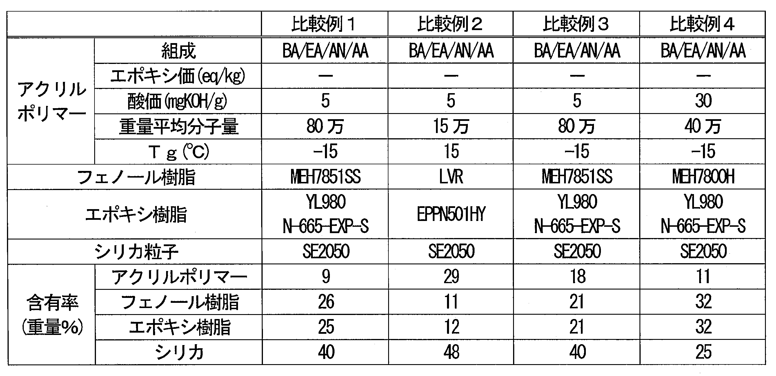
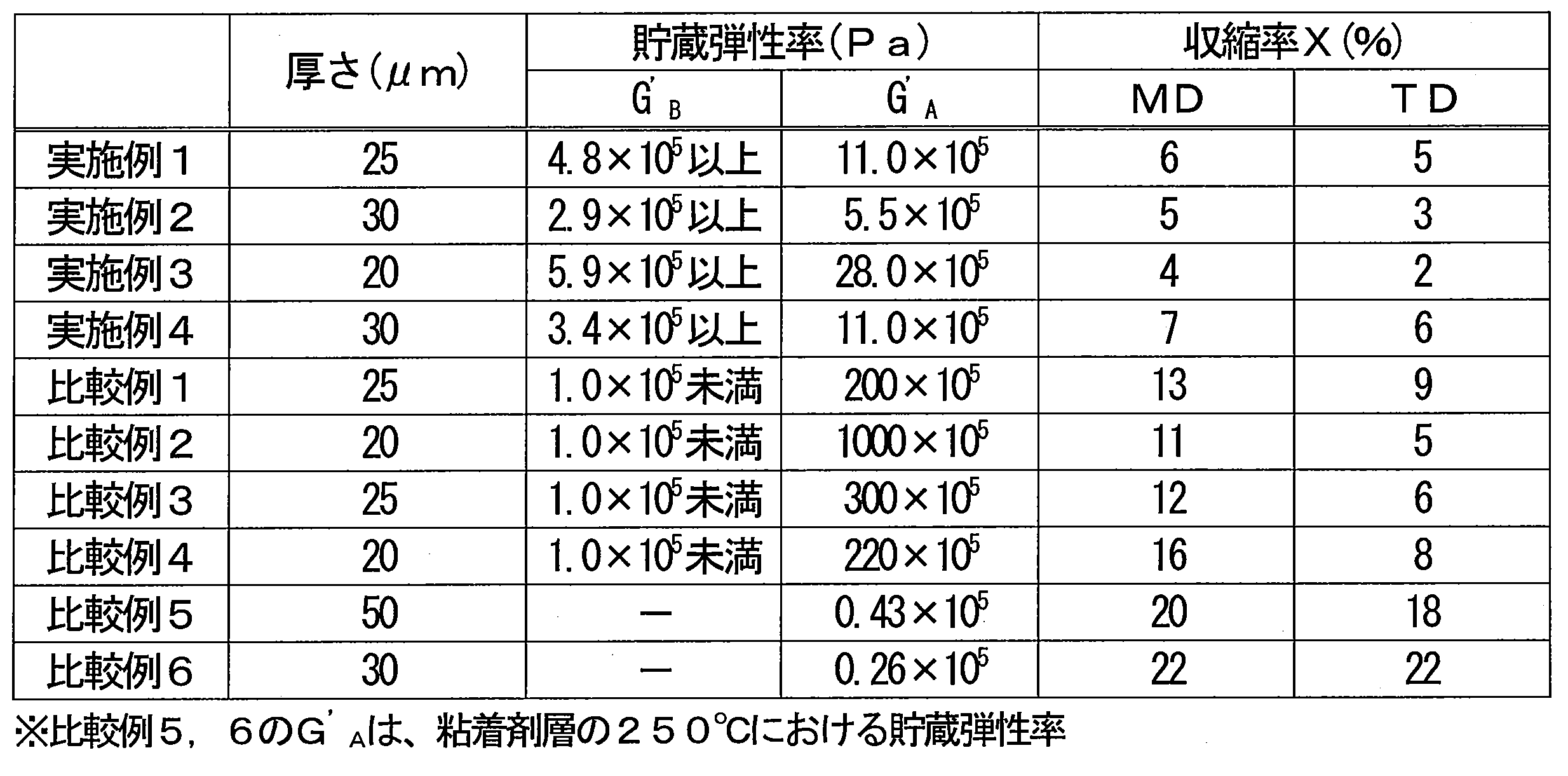
Claims (17)
- 開口を有する面を持つ対象物の前記面に配置される保護カバー部材であって、
前記部材が前記面に配置されたときに前記開口を覆う形状を有する保護膜と、粘着剤層と、を含む積層体から構成され、
前記粘着剤層は、熱硬化性樹脂組成物を含む熱硬化性粘着層を備え、
前記熱硬化性樹脂組成物の貯蔵弾性率は、130~170℃において1×10⁵Pa以上である、保護カバー部材。 - 前記熱硬化性樹脂組成物の熱硬化後の貯蔵弾性率が、250℃において5×10⁵Pa以上である、請求項1に記載の保護カバー部材。
- 前記熱硬化性樹脂組成物がアクリルポリマーを含むアクリル系組成物である、請求項1又は2に記載の保護カバー部材。
- 前記熱硬化性樹脂組成物が、重量平均分子量20万以上のアクリルポリマーを35重量%以上の含有率で含む、請求項1~3のいずれかに記載の保護カバー部材。
- 前記アクリルポリマーが熱硬化性基を有する、請求項3又は4に記載の保護カバー部材。
- 前記熱硬化性基がエポキシ基、カルボキシ基、ヒドロキシ基、カルボニル基、アジリジニル基及びアミノ基から選ばれる少なくとも1種である、請求項5に記載の保護カバー部材。
- 前記熱硬化性樹脂組成物が熱硬化性樹脂を更に含み、
前記熱硬化性樹脂組成物における前記熱硬化性樹脂の含有率は、前記アクリルポリマーの含有率に比べて小さい、請求項3~6のいずれかに記載の保護カバー部材。 - 前記熱硬化性樹脂がフェノール樹脂である、請求項7に記載の保護カバー部材。
- 前記粘着剤層及び/又は前記熱硬化性粘着層が前記保護膜と接している、請求項1~8のいずれかに記載の保護カバー部材。
- 前記粘着剤層及び/又は前記熱硬化性粘着層が、前記対象物の前記面との接合面となる、請求項1~9のいずれかに記載の保護カバー部材。
- 前記積層体は、前記保護膜の一方の主面の側に位置する第1の前記粘着剤層と、前記保護膜の他方の主面の側に位置する第2の前記粘着剤層と、含む、請求項1~10のいずれかに記載の保護カバー部材。
- 前記保護膜は厚さ方向の通気性を有する、請求項1~11のいずれかに記載の保護カバー部材。
- 前記保護膜はポリテトラフルオロエチレン膜を含む、請求項1~12のいずれかに記載の保護カバー部材。
- 前記保護膜の面積が175mm2以下である請求項1~13のいずれかに記載の保護カバー部材。
- 前記保護膜の主面に垂直に見て、
前記粘着剤層は、前記保護膜の周縁部に配置されており、
前記保護膜の中心から前記保護膜の外周に至る線分のうち最短の前記線分の長さL1に対する、前記最短の線分における前記粘着剤層と重複する部分の長さL2の比L2/L1が0.3以下である、請求項1~14のいずれかに記載の保護カバー部材。 - 微小電気機械システム(MEMS)用である、請求項1~15のいずれかに記載の保護カバー部材。
- 基材シートと、前記基材シート上に配置された1又は2以上の保護カバー部材と、を備え、
前記保護カバー部材は、請求項1~16のいずれかに記載の保護カバー部材である部材供給用シート。
Priority Applications (6)
| Application Number | Priority Date | Filing Date | Title |
|---|---|---|---|
| JP2022512286A JP7247419B2 (ja) | 2020-08-07 | 2021-08-05 | 保護カバー部材及び部材供給用シート |
| DE112021004204.1T DE112021004204T5 (de) | 2020-08-07 | 2021-08-05 | Schutzabdeckungselement und Elementzuführungslage |
| US17/801,070 US12060263B2 (en) | 2020-08-07 | 2021-08-05 | Protective cover member and member supplying sheet |
| CN202180008951.1A CN114929825B (zh) | 2020-08-07 | 2021-08-05 | 保护罩构件及构件供给用片 |
| KR1020237007408A KR20230047435A (ko) | 2020-08-07 | 2021-08-05 | 보호 커버 부재 및 부재 공급용 시트 |
| JP2022162781A JP2023014072A (ja) | 2020-08-07 | 2022-10-07 | 保護カバー部材及び部材供給用シート |
Applications Claiming Priority (2)
| Application Number | Priority Date | Filing Date | Title |
|---|---|---|---|
| JP2020-135164 | 2020-08-07 | ||
| JP2020135164 | 2020-08-07 |
Publications (1)
| Publication Number | Publication Date |
|---|---|
| WO2022030604A1 true WO2022030604A1 (ja) | 2022-02-10 |
Family
ID=80118141
Family Applications (1)
| Application Number | Title | Priority Date | Filing Date |
|---|---|---|---|
| PCT/JP2021/029213 Ceased WO2022030604A1 (ja) | 2020-08-07 | 2021-08-05 | 保護カバー部材及び部材供給用シート |
Country Status (7)
| Country | Link |
|---|---|
| US (1) | US12060263B2 (ja) |
| JP (2) | JP7247419B2 (ja) |
| KR (1) | KR20230047435A (ja) |
| CN (1) | CN114929825B (ja) |
| DE (1) | DE112021004204T5 (ja) |
| TW (1) | TW202229001A (ja) |
| WO (1) | WO2022030604A1 (ja) |
Citations (13)
| Publication number | Priority date | Publication date | Assignee | Title |
|---|---|---|---|---|
| JPS63312379A (ja) * | 1987-06-15 | 1988-12-20 | Sekisui Chem Co Ltd | 熱硬化型感圧性接着剤組成物 |
| JPH0776672A (ja) * | 1993-09-07 | 1995-03-20 | Showa Highpolymer Co Ltd | 熱硬化性粘着剤組成物 |
| JPH08148815A (ja) * | 1994-11-17 | 1996-06-07 | Hitachi Chem Co Ltd | フレキシブル印刷配線板用カバーレイフィルム |
| JP2002249737A (ja) * | 2001-02-22 | 2002-09-06 | Nitto Denko Corp | 通気性接着シートの製造方法および通気性接着シート |
| JP2007081881A (ja) * | 2005-09-14 | 2007-03-29 | Nitto Denko Corp | 通音膜、通音膜付き電子部品及びその電子部品を実装した回路基板の製造方法 |
| JP2010000464A (ja) * | 2008-06-20 | 2010-01-07 | Japan Gore Tex Inc | 通気フィルター及びその製造方法 |
| JP2011135042A (ja) * | 2009-11-26 | 2011-07-07 | Nitto Denko Corp | 熱硬化型接着フィルム、ダイシングフィルム付き接着フィルム、及び、該熱硬化型接着フィルム又は該ダイシングフィルム付き接着フィルムを用いた半導体装置の製造方法 |
| JP2012229372A (ja) * | 2011-04-27 | 2012-11-22 | Nitto Denko Corp | 粘着剤組成物及び粘着シート |
| JP2012253481A (ja) * | 2011-06-01 | 2012-12-20 | Nitto Denko Corp | 防水通音部材 |
| WO2015152010A1 (ja) * | 2014-03-31 | 2015-10-08 | 三井化学東セロ株式会社 | 保護フィルム、及び、該保護フィルムを用いる半導体装置の製造方法 |
| JP2017139408A (ja) * | 2016-02-05 | 2017-08-10 | 日立化成株式会社 | 半導体装置中空封止用熱硬化型シート及びそれを用いて中空封止された半導体装置 |
| WO2019089021A1 (en) * | 2017-11-01 | 2019-05-09 | W. L. Gore & Associates, Inc. | Protective cover assembly having improved z-strength |
| JP2019209689A (ja) * | 2018-06-05 | 2019-12-12 | イノックス・アドバンスト・マテリアルズ・カンパニー・リミテッドINNOX Advanced Materials Co.,Ltd. | 帯電防止ダイアタッチフィルム、その製造方法、及びこれを用いたウエハダイシング工程 |
Family Cites Families (6)
| Publication number | Priority date | Publication date | Assignee | Title |
|---|---|---|---|---|
| KR100687995B1 (ko) * | 2001-04-09 | 2007-02-27 | 닛토덴코 가부시키가이샤 | 세정용 라벨 시트 및 세정 기능을 갖는 반송 부재 |
| JP5456712B2 (ja) * | 2008-08-28 | 2014-04-02 | 日東電工株式会社 | 熱硬化型ダイボンドフィルム |
| JP5398083B2 (ja) * | 2011-03-11 | 2014-01-29 | 日東電工株式会社 | ダイボンドフィルム及びその用途 |
| JP6632115B2 (ja) * | 2015-07-17 | 2020-01-15 | 藤森工業株式会社 | 接着性樹脂層及び接着性樹脂フィルム |
| JP7340457B2 (ja) * | 2017-12-26 | 2023-09-07 | リンテック株式会社 | 粘着性積層体、樹脂膜付き加工対象物の製造方法、及び硬化樹脂膜付き硬化封止体の製造方法 |
| DE112021001702T5 (de) * | 2020-03-18 | 2023-02-23 | Nitto Denko Corporation | Schutzabdeckungselement und elementzuführungslage |
-
2021
- 2021-08-05 CN CN202180008951.1A patent/CN114929825B/zh active Active
- 2021-08-05 KR KR1020237007408A patent/KR20230047435A/ko active Pending
- 2021-08-05 DE DE112021004204.1T patent/DE112021004204T5/de active Pending
- 2021-08-05 US US17/801,070 patent/US12060263B2/en active Active
- 2021-08-05 JP JP2022512286A patent/JP7247419B2/ja active Active
- 2021-08-05 WO PCT/JP2021/029213 patent/WO2022030604A1/ja not_active Ceased
- 2021-08-06 TW TW110129064A patent/TW202229001A/zh unknown
-
2022
- 2022-10-07 JP JP2022162781A patent/JP2023014072A/ja active Pending
Patent Citations (13)
| Publication number | Priority date | Publication date | Assignee | Title |
|---|---|---|---|---|
| JPS63312379A (ja) * | 1987-06-15 | 1988-12-20 | Sekisui Chem Co Ltd | 熱硬化型感圧性接着剤組成物 |
| JPH0776672A (ja) * | 1993-09-07 | 1995-03-20 | Showa Highpolymer Co Ltd | 熱硬化性粘着剤組成物 |
| JPH08148815A (ja) * | 1994-11-17 | 1996-06-07 | Hitachi Chem Co Ltd | フレキシブル印刷配線板用カバーレイフィルム |
| JP2002249737A (ja) * | 2001-02-22 | 2002-09-06 | Nitto Denko Corp | 通気性接着シートの製造方法および通気性接着シート |
| JP2007081881A (ja) * | 2005-09-14 | 2007-03-29 | Nitto Denko Corp | 通音膜、通音膜付き電子部品及びその電子部品を実装した回路基板の製造方法 |
| JP2010000464A (ja) * | 2008-06-20 | 2010-01-07 | Japan Gore Tex Inc | 通気フィルター及びその製造方法 |
| JP2011135042A (ja) * | 2009-11-26 | 2011-07-07 | Nitto Denko Corp | 熱硬化型接着フィルム、ダイシングフィルム付き接着フィルム、及び、該熱硬化型接着フィルム又は該ダイシングフィルム付き接着フィルムを用いた半導体装置の製造方法 |
| JP2012229372A (ja) * | 2011-04-27 | 2012-11-22 | Nitto Denko Corp | 粘着剤組成物及び粘着シート |
| JP2012253481A (ja) * | 2011-06-01 | 2012-12-20 | Nitto Denko Corp | 防水通音部材 |
| WO2015152010A1 (ja) * | 2014-03-31 | 2015-10-08 | 三井化学東セロ株式会社 | 保護フィルム、及び、該保護フィルムを用いる半導体装置の製造方法 |
| JP2017139408A (ja) * | 2016-02-05 | 2017-08-10 | 日立化成株式会社 | 半導体装置中空封止用熱硬化型シート及びそれを用いて中空封止された半導体装置 |
| WO2019089021A1 (en) * | 2017-11-01 | 2019-05-09 | W. L. Gore & Associates, Inc. | Protective cover assembly having improved z-strength |
| JP2019209689A (ja) * | 2018-06-05 | 2019-12-12 | イノックス・アドバンスト・マテリアルズ・カンパニー・リミテッドINNOX Advanced Materials Co.,Ltd. | 帯電防止ダイアタッチフィルム、その製造方法、及びこれを用いたウエハダイシング工程 |
Also Published As
| Publication number | Publication date |
|---|---|
| JP7247419B2 (ja) | 2023-03-28 |
| CN114929825A (zh) | 2022-08-19 |
| US12060263B2 (en) | 2024-08-13 |
| US20230159321A1 (en) | 2023-05-25 |
| JP2023014072A (ja) | 2023-01-26 |
| JPWO2022030604A1 (ja) | 2022-02-10 |
| TW202229001A (zh) | 2022-08-01 |
| DE112021004204T5 (de) | 2023-06-01 |
| CN114929825B (zh) | 2024-03-19 |
| KR20230047435A (ko) | 2023-04-07 |
Similar Documents
| Publication | Publication Date | Title |
|---|---|---|
| KR102007111B1 (ko) | 반도체 가공용 테이프 | |
| KR101549285B1 (ko) | 반도체소자 탑재 기판 | |
| JPWO2020013250A1 (ja) | 半導体装置の製造方法、熱硬化性樹脂組成物及びダイシング・ダイボンディング一体型フィルム | |
| JP5196034B2 (ja) | 接着シート | |
| JP2019042976A (ja) | 樹脂シート、半導体装置、および樹脂シートの使用方法 | |
| JP6237906B2 (ja) | 電子部品用樹脂シート、保護フィルム付電子部品用樹脂シートならびに半導体装置およびその製造方法 | |
| JP2017005160A (ja) | ウエハ加工用テープ | |
| JP4876317B2 (ja) | 半導体装置用接着剤組成物およびそれを用いた半導体装置用接着剤シート、半導体接続用基板ならびに半導体装置 | |
| JP7247419B2 (ja) | 保護カバー部材及び部材供給用シート | |
| JP6988923B2 (ja) | 半導体装置の製造方法、及びフィルム状接着剤 | |
| JP2017161881A (ja) | 感光性樹脂シート、電子装置、および電子装置の製造方法 | |
| WO2023277190A1 (ja) | 保護カバー部材、部材供給用シート及び微小電気機械システム | |
| WO2014083973A1 (ja) | 半導体装置の製造方法 | |
| KR102578510B1 (ko) | 반도체 장치 제조용 접착 필름 및 그 제조 방법, 그리고, 반도체 장치 및 그 제조 방법 | |
| JP2005247953A (ja) | 半導体用接着剤組成物およびそれを用いた半導体用接着剤シート | |
| JP2012044193A (ja) | 半導体装置用接着剤シートおよびそれを用いた半導体装置用部品ならびに半導体装置 | |
| JPWO2019026266A1 (ja) | 半導体装置の製造方法 | |
| TWI827551B (zh) | 半導體裝置製造用接著膜以及半導體裝置及其製造方法 | |
| JP7140143B2 (ja) | 半導体装置の製造方法、及びフィルム状接着剤 | |
| WO2023048188A1 (ja) | フィルム状接着剤、ダイシング・ダイボンディング一体型フィルム、並びに半導体装置及びその製造方法 | |
| JP2007266394A (ja) | 半導体用接着剤シート、これを用いた半導体接続用基板および半導体装置 | |
| JP2022154844A (ja) | 接着剤片付きフィルム、接続体の製造方法、及び接着剤組成物 | |
| JPWO2019026267A1 (ja) | 半導体装置の製造方法および積層シート | |
| JP2004263089A (ja) | 半導体装置用接着剤組成物およびそれを用いた半導体装置用接着剤シート、半導体接続用基板ならびに半導体装置 | |
| JP2003301162A (ja) | 半導体装置用接着剤組成物およびそれを用いた半導体装置用接着剤シート、半導体接続用基板、半導体装置 |
Legal Events
| Date | Code | Title | Description |
|---|---|---|---|
| ENP | Entry into the national phase |
Ref document number: 2022512286 Country of ref document: JP Kind code of ref document: A |
|
| 121 | Ep: the epo has been informed by wipo that ep was designated in this application |
Ref document number: 21853904 Country of ref document: EP Kind code of ref document: A1 |
|
| ENP | Entry into the national phase |
Ref document number: 20237007408 Country of ref document: KR Kind code of ref document: A |
|
| 122 | Ep: pct application non-entry in european phase |
Ref document number: 21853904 Country of ref document: EP Kind code of ref document: A1 |