WO2022004485A1 - 工具交換装置と工作機械 - Google Patents
工具交換装置と工作機械 Download PDFInfo
- Publication number
- WO2022004485A1 WO2022004485A1 PCT/JP2021/023565 JP2021023565W WO2022004485A1 WO 2022004485 A1 WO2022004485 A1 WO 2022004485A1 JP 2021023565 W JP2021023565 W JP 2021023565W WO 2022004485 A1 WO2022004485 A1 WO 2022004485A1
- Authority
- WO
- WIPO (PCT)
- Prior art keywords
- magazine
- tool
- arm
- center
- support
- Prior art date
- Legal status (The legal status is an assumption and is not a legal conclusion. Google has not performed a legal analysis and makes no representation as to the accuracy of the status listed.)
- Ceased
Links
Images





Classifications
-
- B—PERFORMING OPERATIONS; TRANSPORTING
- B23—MACHINE TOOLS; METAL-WORKING NOT OTHERWISE PROVIDED FOR
- B23Q—DETAILS, COMPONENTS, OR ACCESSORIES FOR MACHINE TOOLS, e.g. ARRANGEMENTS FOR COPYING OR CONTROLLING; MACHINE TOOLS IN GENERAL CHARACTERISED BY THE CONSTRUCTION OF PARTICULAR DETAILS OR COMPONENTS; COMBINATIONS OR ASSOCIATIONS OF METAL-WORKING MACHINES, NOT DIRECTED TO A PARTICULAR RESULT
- B23Q3/00—Devices holding, supporting, or positioning work or tools, of a kind normally removable from the machine
- B23Q3/155—Arrangements for automatic insertion or removal of tools, e.g. combined with manual handling
- B23Q3/157—Arrangements for automatic insertion or removal of tools, e.g. combined with manual handling of rotary tools
- B23Q3/15713—Arrangements for automatic insertion or removal of tools, e.g. combined with manual handling of rotary tools a transfer device taking a single tool from a storage device and inserting it in a spindle
- B23Q3/1572—Arrangements for automatic insertion or removal of tools, e.g. combined with manual handling of rotary tools a transfer device taking a single tool from a storage device and inserting it in a spindle the storage device comprising rotating or circulating storing means
- B23Q3/15722—Rotary discs or drums
-
- B—PERFORMING OPERATIONS; TRANSPORTING
- B23—MACHINE TOOLS; METAL-WORKING NOT OTHERWISE PROVIDED FOR
- B23Q—DETAILS, COMPONENTS, OR ACCESSORIES FOR MACHINE TOOLS, e.g. ARRANGEMENTS FOR COPYING OR CONTROLLING; MACHINE TOOLS IN GENERAL CHARACTERISED BY THE CONSTRUCTION OF PARTICULAR DETAILS OR COMPONENTS; COMBINATIONS OR ASSOCIATIONS OF METAL-WORKING MACHINES, NOT DIRECTED TO A PARTICULAR RESULT
- B23Q3/00—Devices holding, supporting, or positioning work or tools, of a kind normally removable from the machine
- B23Q3/155—Arrangements for automatic insertion or removal of tools, e.g. combined with manual handling
- B23Q3/1552—Arrangements for automatic insertion or removal of tools, e.g. combined with manual handling parts of devices for automatically inserting or removing tools
- B23Q3/15526—Storage devices; Drive mechanisms therefor
- B23Q3/15534—Magazines mounted on the spindle
-
- B—PERFORMING OPERATIONS; TRANSPORTING
- B23—MACHINE TOOLS; METAL-WORKING NOT OTHERWISE PROVIDED FOR
- B23Q—DETAILS, COMPONENTS, OR ACCESSORIES FOR MACHINE TOOLS, e.g. ARRANGEMENTS FOR COPYING OR CONTROLLING; MACHINE TOOLS IN GENERAL CHARACTERISED BY THE CONSTRUCTION OF PARTICULAR DETAILS OR COMPONENTS; COMBINATIONS OR ASSOCIATIONS OF METAL-WORKING MACHINES, NOT DIRECTED TO A PARTICULAR RESULT
- B23Q3/00—Devices holding, supporting, or positioning work or tools, of a kind normally removable from the machine
- B23Q3/155—Arrangements for automatic insertion or removal of tools, e.g. combined with manual handling
- B23Q3/1552—Arrangements for automatic insertion or removal of tools, e.g. combined with manual handling parts of devices for automatically inserting or removing tools
- B23Q3/15526—Storage devices; Drive mechanisms therefor
- B23Q3/15539—Plural magazines, e.g. involving tool transfer from one magazine to another
-
- B—PERFORMING OPERATIONS; TRANSPORTING
- B23—MACHINE TOOLS; METAL-WORKING NOT OTHERWISE PROVIDED FOR
- B23Q—DETAILS, COMPONENTS, OR ACCESSORIES FOR MACHINE TOOLS, e.g. ARRANGEMENTS FOR COPYING OR CONTROLLING; MACHINE TOOLS IN GENERAL CHARACTERISED BY THE CONSTRUCTION OF PARTICULAR DETAILS OR COMPONENTS; COMBINATIONS OR ASSOCIATIONS OF METAL-WORKING MACHINES, NOT DIRECTED TO A PARTICULAR RESULT
- B23Q3/00—Devices holding, supporting, or positioning work or tools, of a kind normally removable from the machine
- B23Q3/155—Arrangements for automatic insertion or removal of tools, e.g. combined with manual handling
- B23Q3/1552—Arrangements for automatic insertion or removal of tools, e.g. combined with manual handling parts of devices for automatically inserting or removing tools
- B23Q3/1554—Transfer mechanisms, e.g. tool gripping arms; Drive mechanisms therefore
- B23Q2003/155414—Transfer mechanisms, e.g. tool gripping arms; Drive mechanisms therefore the transfer mechanism comprising two or more grippers
Definitions
- This technology relates to tool changers and machine tools with tool magazines.
- Vibration may occur when passing tools between the main magazine and the sub magazine.
- the vibration propagates to the spindle of the machine tool, the work holding portion, and the like.
- the machine tool vibrates during machining, which causes a problem that the machining accuracy of the workpiece is lowered.
- the present disclosure aims to provide a tool changer and a machine tool that have a plurality of magazines for storing tools and suppress the generation of vibration.
- the present invention is a tool changing device for exchanging tools between a first magazine and a second magazine for storing tools, in which the center of gravity of the second magazine is below the tool exchange positions of the first magazine and the second magazine. To place.
- the second magazine is stable and the generation of vibration in the second magazine can be suppressed.
- the first magazine of the present invention stores the tools to be mounted on the spindle of the machine tool, and the second magazine stores the tools stored in the first magazine.
- the tool changer of the present invention can store more tools than one magazine by providing two magazines.
- the second magazine of the tool changer of the present invention rotates around an axis inclined with respect to a horizontal plane.
- the center of gravity of the second magazine is lowered because the second magazine is tilted with respect to the horizontal plane.
- the second magazine of the tool changer of the present invention includes a support disk and an arm provided on the peripheral edge of the support disk to hold a tool, and one end of the arm is outside the radial direction of the support disk from the peripheral edge. Protruding in the direction, the other end of the arm is arranged at a position not opposed to the center of the support disk.
- the arm of the tool changer is arranged so as to intersect the line extending in the radial direction passing through the center of the support disk. Therefore, the center of gravity of the second magazine of the tool changer is lowered.
- the arm of the tool changer of the present invention includes a support plate fixed to the second magazine and two support rods rotating on both sides of the support plate, one of which is the center of rotation of the second magazine.
- the first portion extending in a direction orthogonal to the axis, the first inclined portion extending in one direction parallel to the axis of the center of rotation from one end of the first portion, and the other end portion of the first portion on the same side as one direction. It has a first grip that is provided and grips the tool, and the other support rod has a second portion that extends in a direction perpendicular to the axis of the center of rotation and a shaft of the center of rotation from one end of the second portion.
- It has a second inclined portion that extends in the other direction parallel to the other direction, and a second grip portion that is fixed to the same side as the other direction at the other end of the second portion and grips the tool, and has a center of rotation. In the axial direction, the first grip and the second grip are in the same position.
- the direction in which the first inclined portion and the second inclined portion extend is opposite, and the fixed positions of the first grip portion and the second grip portion are opposite, so that the first grip portion and the second grip portion are opposite.
- the fixed position of the part is the same position.
- For the tool changer prepare two identical support rods and arrange them in opposite directions. Therefore, since the support rods on both sides are the same part, it is easy to manage.
- the second magazine of the tool changer of the present invention includes a moving mechanism that moves in the radial direction and a pot that is provided in the moving mechanism and holds the tool.
- the pot grips the tool, and the moving mechanism transports the tool gripped by the pot between the first magazine and the second magazine. Since the pot moves in the radial direction, the design of the moving mechanism is easy.
- the moving mechanism of the tool changer of the present invention is located above the center of the second magazine.
- the machine tool of the present invention is provided with the above-mentioned tool changer.
- the machine tool places the center of gravity of the second magazine below the tool exchange position of the first magazine and the second magazine. Therefore, the machine tool can suppress the generation of vibration.
- the center of gravity of the second magazine is arranged below the tool change positions of the first magazine and the second magazine, so that the second magazine is stable and vibrations in the second magazine. Can be suppressed.
- FIG. 6 is a schematic cross-sectional view taken along the line VV shown in FIG. 4 as a cutting line.
- Rear perspective view near the second magazine Schematic perspective view of the arm viewed from the upper left direction. Schematic perspective view of the arm viewed from the upper right. Schematic front view of the arm. Top view of the arm. Schematic left side view of the arm. Schematic bottom view of the arm. Enlarged perspective view of a schematic portion of the configuration near the arm. Schematic front view of the arm gripping the tool.
- FIG. 1 Schematic rear view of the arm gripping the tool.
- the second showing the relationship between the vertical distance between the installation surface of the machine tool and the center of gravity of the second magazine and the vertical distance between the installation surface and the tool exchange position when the other end of the arm is not opposed to the center.
- Right side view of the magazine The second magazine showing the relationship between the distance between the installation surface of the machine tool and the center of gravity of the second magazine and the distance between the installation surface and the tool change position when the other end of the arm faces the central axis. Reference right side view.
- L indicates a horizontal plane
- L1 indicates a central axis of the second magazine 8.
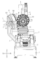
- the machine tool includes a base 1, a work holding portion 2, an XY moving mechanism 3, a vertical column 4, a Z moving mechanism 5, a first magazine 6, a support portion 7, a second magazine 8, a tool transfer device (not shown), and a spindle head. It is equipped with 10 mag.
- the first magazine 6, the support portion 7, the second magazine 8, and the tool transfer device constitute a tool changer.
- Base 1 forms a rectangular shape in a plan view and extends in the front-back direction.
- a work holding portion 2 is provided on the upper front side of the base 1.
- an XY moving mechanism 3 that can move in the left-right direction (X direction) and the front-back direction (Y direction) is provided on the rear side of the work holding portion 2.
- a vertical pillar 4 is provided on the upper side of the XY movement mechanism 3.
- a Z moving mechanism 5 that can move in the vertical direction (Z direction) is provided on the front surface of the vertical column 4.
- the spindle head 10 is provided in the Z moving mechanism 5.
- the spindle head 10 includes a spindle extending up and down. A tool is attached to the lower end of the spindle.
- the first magazine 6 is provided on the front side of the spindle head 10.
- the first magazine 6 is connected to the vertical column 4 via a connecting member.
- the first magazine 6 includes a disk 6a and an arm 6b.
- a motor (not shown) is connected to the disk 6a, and the disk 6a rotates around its central axis by driving the motor.
- a plurality of arms 6b are radially provided on the peripheral edge of the disk 6a. The arm 6b holds the tool.
- the first magazine 6 is arranged so that the central axis of the disk 6a extends in the front-rear direction and the disk 6a is in a forward leaning posture.
- the lower end position of the first magazine 6 is the tool change position.
- the arm 6b holding the tool is arranged at the tool replacement position, and the Z moving mechanism 5 is moved downward.
- the spindle is equipped with a tool gripped by the arm 6b.
- an empty arm 6b is placed at the tool replacement position, and the Z moving mechanism 5 is moved upward. Based on the upward movement of the Z moving mechanism 5, the arm 6b grips the tool of the spindle, and the tool is removed from the spindle.
- the tool attached to the spindle processes the work held in the work holding part 2.
- the XY moving mechanism 3 adjusts the front-back and left-right positions of the tool (spindle) with respect to the work, and the Z-moving mechanism 5 adjusts the vertical position of the tool.
- the support portion 7 is provided on the rear side of the left portion of the base 1.
- the support portion 7 extends upward, and the second magazine 8 is provided at the tip portion thereof.
- the second magazine 8 is arranged on the left side and the rear side of the first magazine 6.
- the second magazine 8 includes a tool transfer device. The tool transfer device transfers tools between the arm 6b of the first magazine 6 and the arm 8b of the second magazine 8.
- FIG. 2 is a view viewed from the axial direction of the support disk 8a.
- the second magazine 8 includes a support disk 8a and an arm 8b.
- a motor (not shown) is connected to the support disk 8a, and the support disk 8a is rotated around the central axis L1 (see FIG. 1) by driving the motor.
- the central axis L1 of the support disk 8a is the axis of the center of rotation, which is a virtual axis.
- one side of the support disk 8a faces diagonally rearward to the right, the other side faces diagonally forward to the left, and the central axis L1 intersects the horizontal plane L.
- the central axis L1 extends diagonally forward to the left and diagonally backward to the right.
- the front side of the central axis L1 is located below the horizontal plane L, and the rear side of the central axis L1 is located above the horizontal plane L.
- the central axis L1 and the horizontal plane L form a predetermined angle ⁇ .
- the arm 6b of the first magazine 6 and the arm 8b of the second magazine 8 are closest to each other at a position lower than the horizontal plane L.
- the closest position is the magazine tool exchange position P for exchanging the tool of the first magazine 6 and the tool of the second magazine 8.
- the arm 6b of the first magazine 6 arranged at the magazine tool replacement position P will be referred to as a replacement position arm 6c
- the arm 8b of the second magazine 8 will be referred to as a replacement position arm 8c.
- the machine tool exchanges tools between the exchange position arm 6c and the exchange position arm 8c.
- the center of gravity 8g of the second magazine 8 is arranged below the horizontal plane L, that is, below the magazine tool replacement position P.
- the center of gravity 8 g of the second magazine 8 is arranged below the magazine tool exchange position P of the first magazine 6 and the second magazine 8, the second magazine 8 is stable and vibration is generated in the second magazine 8. Can be suppressed.
- FIG. 3 is a schematic reference front view of a conventional machine tool.
- La in FIG. 3 indicates the vertical position of the magazine tool replacement position Pa.
- the central axis L4 of the second magazine 8A is parallel to the horizontal plane L.
- the center of gravity 8G of the second magazine 8A is located above the magazine tool replacement position Pa. Since the machine tool of FIG. 3 has a center of gravity higher than that of the machine tool of FIG. 1, the second magazine 8A tends to be unstable, and it is difficult to suppress the vibration in the second magazine 8A.
- the second magazine 8 Since the center of gravity 8g of the second magazine 8 in FIG. 1 is arranged below the magazine tool replacement position P, the second magazine 8 is stable, and the machine tool can suppress the generation of vibration in the second magazine 8.
- the second magazine 8 may be provided on the right side of the first magazine 6.
- the cutting line in FIG. 5 is orthogonal to the central axis of the support disk 81.
- the first magazine 6 includes a cover 6d.
- the cover 6d covers the outside of each arm 6b.
- the cover 6d is rotatable and rotates together with the arm 6b when the tool is exchanged with the spindle, and does not interfere with the tool exchange.
- the mounting member 70 is fixed to the upper end portion of the support portion 7.
- the mounting member 70 includes a front plate portion 70a, a rear plate portion 70b, and a support cylinder 70c.
- the front plate portion 70a and the rear plate portion 70b extend in the upper right direction from the upper end portion of the support portion 7 and are arranged in the front-rear direction.
- the support cylinder 70c is connected to the upper end portions of the front plate portion 70a and the rear plate portion 70b with the left-right direction as the axial direction.
- the reduction gear device 71 Connect the reduction gear device 71 to the right part of the support cylinder 70c.
- the reduction gear device 71 has an annular inner peripheral portion 72 and an outer peripheral portion 73.
- the inner peripheral portion 72 is fixed to the peripheral portion of the support cylinder 70c.
- the outer peripheral portion 73 is rotatably attached around the inner peripheral portion 72 around the axis. That is, the inner peripheral portion 72 rotatably supports the outer peripheral portion 73.
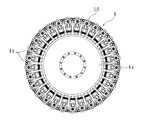
- the second magazine 80 includes a support disk 81, a motor 82, and an arm 83.
- the motor 82 is connected to the left portion of the support cylinder 70c.
- the support disk 81 is arranged on the right side of the reduction gear device 71 with both sides facing left and right.
- the right side of the support disk 81 faces slightly backward, and the left side faces slightly forward.
- a through hole 81b (see FIG. 5) penetrating to the left and right is provided at the center of the support disk 81.
- the support cylinder 70c and the inner peripheral portion 72 extend in the axial direction and are inserted into the through hole 81b.
- the outer peripheral portion 73 is connected to the inner peripheral portion of the through hole 81b.
- the outer peripheral portion 73 is rotated by the drive of the motor 82, and the support disk 81 is rotated around its central axis.
- a plurality of arms 83 are provided radially on the peripheral edge of the support disk 81. The arm 83 holds the tool.
- the gripping arm 6b of the first magazine 6 and the gripping arm 83 of the second magazine 80 are closest to each other at a position below the center 81a.
- the closest position is the magazine tool exchange position P for exchanging the tool of the first magazine 6 and the tool of the second magazine 80.
- the arm 6b of the first magazine 6 arranged at the magazine tool exchange position P is referred to as an exchange position arm 6c
- the gripping arm 83 of the second magazine 80 is referred to as an exchange position arm 84.
- a tool is exchanged between the exchange position arm 6c and the exchange position arm 84.
- One end portion 83f of the gripping arm 83 projects radially outward from the peripheral edge portion of the support disk 81.
- L2 shows a line passing through the central axis 81a of the support disk 81 and the center of the tool 50 gripped by the replacement position arm 84
- L3 shows a line along the longitudinal direction of the replacement position arm 84. ..
- the line L3 passes through the center of the replacement position arm 84.
- the line L2 and the line L3 intersect to form a predetermined angle ⁇ 1 (> 0). Since each arm 83 located at the magazine tool exchange position P is arranged so as to form a predetermined angle ⁇ 1, the other end portion 83 g of the arm 83 is not opposed to the central axis 81a of the support disk 81.
- a tool transfer device 9 is provided on the right side of the support disk 81.
- the tool transfer device 9 includes a motor 9a, a ball screw 9b, a nut 9c, a track 9d, a slider 9e, a pot 9f, and a connecting portion 9g.
- the motor 9a, the ball screw 9b, the nut 9c, the track 9d, the slider 9e, and the connecting portion 9g constitute a moving mechanism.
- the moving mechanism is located above the central axis 81a of the support disk 81.
- the support cylinder 70c and the inner peripheral portion 72 inserted into the through hole 81b support the ball screw 9b and the track 9d.
- the ball screw 9b is connected to the rotation shaft of the motor 9a.
- the nut 9c is connected to the ball screw 9b.
- the track 9d is arranged next to the ball screw 9b.
- the track 9d is fixed at a position deviated from the central axis 81a of the support disk 81.
- the orbit 9d extends along the longitudinal direction of the replacement position arm 84.
- One end of the track 9d faces the exchange position arm 84.
- the slider 9e is slidably provided on the track 9d.
- the pot 9f is attached to the slider 9e.
- the connecting portion 9g connects the slider 9e and the nut 9c.
- the pot 9f grabs the tool 50 gripped by the replacement position arm 84 and passes it to the empty replacement position arm 6c, or grabs the tool 50 gripped by the replacement position arm 6c and passes it to the empty replacement position arm 84.
- the center of gravity 8g of the second magazine 80 is located near the central axis 81a and is located below the center of the first magazine 6.
- the plurality of arms 83 are arranged along the peripheral edge of the support disk 81.
- the arm 83 extends in the radial direction of the support disk 81.
- the configuration of the arm 83 will be described.
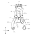
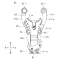
- the arm 83 includes a first support rod 831 and a second support rod 832.
- the support plate 83a, the first support rod 831 and the second support rod 832 extend in the front-rear direction.
- the front end portion of the support plate 83a has a circular arc shape in a plan view protruding to the rear side.
- the first support rod 831 and the second support rod 832 are separated from each other in the left-right direction, and are arranged on the left side and the right side of the support plate 83a, respectively.
- the front-rear midway portion of the first support rod 831 is connected to the front-rear halfway portion of the support plate 83a via a pivot axis 83d whose axial direction is the vertical direction.
- the front-rear midway portion of the second support rod 832 is connected to the front-rear halfway portion of the support plate 83a via a pivot axis 83e whose axial direction is the vertical direction.
- the front side of the first support rod 831 from the pivot 83d is referred to as a front portion 831d
- the rear side of the pivot rod 83d is referred to as a rear portion 831e
- the front side of the second support rod 832 from the pivot 83e is referred to as a front portion 832d
- the rear side of the pivot rod 83e is referred to as a rear portion 832e.
- the front portion 831d of the first support rod 831 is curved so as to project to the left side.
- the front portion 832d of the second support rod 832 is curved so as to project to the right.
- the front end portion of the arc-shaped support plate 83a is arranged between the front side portions 831d and 832d of the first support rod 831 and the second support rod 832.
- a spring seat 831c is provided at the rear end of the first support rod 831.
- a spring seat 832c is provided at the rear end of the second support rod 832.
- the two spring seats 831c and 832c form a disk shape and face each other in the left-right direction.
- a push spring 83c is provided between the two spring seats 831c and 832c. The push spring 83c urges the two spring seats 831c and 832c so that the two spring seats 831c and 832c are separated from each other in the left-right direction.
- the front side portion 831d of the first support rod 831 is located on the left side of the rear side portion 831e.
- the inclined portion 831a connects the front side portion 831d and the rear side portion 831e.
- the inclined portion 831a is inclined so as to extend downward from the rear end portion of the front side portion 831d toward the rear side.
- the roller 831b is provided on the lower surface of the front end portion of the front side portion 831d.
- the front side portion 831d constitutes the first portion
- the inclined portion 831a constitutes the first inclined portion.
- the roller 831b constitutes the first grip portion.
- the vertical direction is a direction parallel to the axial direction of the rotation center of the second magazine 80.
- the front side portion 832d of the second support rod 832 is located on the right side of the rear side portion 832e.
- An inclined portion 832a connects the front side portion 832d and the rear side portion 832e.
- the inclined portion 832a is inclined so as to extend upward from the rear end portion of the front side portion 832d toward the rear side.
- the roller 832b is provided on the upper surface of the front end portion of the front side portion 832d.
- the front side portion 832d constitutes the second portion
- the inclined portion 832a constitutes the second inclined portion
- the roller 832b constitutes the second grip portion.
- the first support rod 831 and the second support rod 832 are the same parts and are only upside down.
- the positions of the pivot axis 83d and the pivot axis 83e are the same in the direction parallel to the axial direction of the rotation center of the tool magazine 80.
- the inclined directions of the inclined portion 831a and the inclined portion 832a are opposite to each other, and the magnitudes of the inclined portions are the same.
- the lengths of the inclined portion 831a and the inclined portion 832a are the same. Therefore, the positions of the roller 831b and the roller 832b are the same in the direction parallel to the axial direction of the rotation center of the tool magazine.
- the plurality of arms 83 are arranged along the peripheral edge of the support disk 81.
- the plurality of arms 83 include a first arm 83A and a second arm 83B located next to the first arm 83A.
- the front portion 831d of the first arm 83A is located above the front portion 832d of the second arm 83B. That is, in the adjacent first arm 83A and the second arm 83B, the positions of the front side portion 831d of the first arm 83A and the front side portion 832d of the second arm 83B are displaced in the vertical direction, that is, in the axial direction of the support disk 81.
- the first arm 83A and the second arm 83B that is, the two adjacent arms 83 are at least partially in the circumferential direction of the support disk 81.
- the front side portions 831d and 832d overlap in the direction parallel to the central axis 81a, in other words, the positions of the front side portions 831d and 832d are displaced in the axial direction of the support disk 81, so that the two adjacent arms 83 interfere with each other in the circumferential direction. do not do.
- the tool 50 is mounted between the front side portions 831d and 832d of the first support rod 831 and the second support rod 832.
- the rollers 831b and 832b hold the tool 50 by the urging force of the push spring 83c.
- D indicates the vertical distance between the installation surface 100 of the machine tool and the center of gravity 8 g of the second magazine 80
- S indicates the vertical distance between the installation surface 100 and the magazine tool exchange position P.
- the line Lb indicates the vertical position of the magazine tool replacement position P.
- the center of gravity 8g of the second magazine 80 is located near the central axis 81a of the second magazine 80, and is located below the magazine tool replacement position P. That is, the exchange position arms 6c and 84 are located above the center of gravity 8g, and the distance D is shorter than the distance S.
- the line L3 passing through the center of the exchange position arm 84 is horizontal, and the exchange position arm 84 faces the exchange position arm 6c.
- FIG. 17 is a diagram corresponding to FIG. 16 when the other end of the arm 8b faces the central axis L1.
- the configuration of the second magazine 8 is the same as the configuration of the second magazine 8 of FIGS. 1 and 2.
- One end 8ba of the arm 8b projects radially outward from the peripheral edge of the support disk 8a.
- the other end 8bb of the arm 8b faces the central axis L1 of the support disk 8a. Since the position of the replacement position arm 6c and the magazine tool replacement position P are the same in FIGS. 16 and 17, the distance S is also the same.
- the center of gravity 8g of the second magazine 8 is located near the central axis L1 of the second magazine 8 and is below the magazine tool replacement position P.
- the line L3 passing through the center of the exchange position arm 8c is slanted, and the exchange position arm 8c does not face the exchange position arm 6c. Therefore, when the tool is exchanged between the exchange position arms 8c and 6c, problems such as incomplete gripping of the tool or dropping of the tool may occur.
- the replacement position arm 84 has a replacement position arm 84 as compared with the case where the other end portion 8bb faces the central shaft L1.
- the distance between the installation surface 100 and the center of gravity 8g can be shortened while facing the exchange position arm 6c. That is, the smooth execution of tool change can be realized, and the center of gravity 8 g of the second magazine 80 can be lowered.
- the pot 9f grips the tool 50, and the moving mechanism conveys the tool 50 gripped by the pot 9f between the first magazine 6 and the second magazine 80. Since the moving mechanism changes tools on the upper side of the center of the second magazine 80, it is easy to lower the position of the second magazine 80.
- the central axis (axis of the center of rotation) L1 of the first magazine 6 may be inclined with respect to the horizontal plane, or may be parallel to the horizontal plane.
- the illustration of the tool transfer device is omitted in the first embodiment, it has the same configuration as the tool transfer device of the first embodiment and the tool transfer device 9 of the second embodiment.
- Tool transfer device 9a Motor (movement mechanism) 9b ball screw (movement mechanism) 9c nut (movement mechanism) 9d orbit (movement mechanism) 9e slider (movement mechanism) 9f pot 9g connecting part (moving mechanism) P, Pa Magazine tool replacement position
Landscapes
- Engineering & Computer Science (AREA)
- Mechanical Engineering (AREA)
- Automatic Tool Replacement In Machine Tools (AREA)
Priority Applications (4)
| Application Number | Priority Date | Filing Date | Title |
|---|---|---|---|
| DE112021001993.7T DE112021001993T5 (de) | 2020-06-30 | 2021-06-22 | Werkzeugwechsler und werkzeugmaschine |
| CN202180044751.1A CN115720539B (zh) | 2020-06-30 | 2021-06-22 | 换刀装置和机床 |
| JP2022533889A JP7552693B2 (ja) | 2020-06-30 | 2021-06-22 | 工具交換装置と工作機械 |
| US18/058,098 US20230082204A1 (en) | 2020-06-30 | 2022-11-22 | Tool changer and machine tool |
Applications Claiming Priority (2)
| Application Number | Priority Date | Filing Date | Title |
|---|---|---|---|
| JP2020-113511 | 2020-06-30 | ||
| JP2020113511 | 2020-06-30 |
Related Child Applications (1)
| Application Number | Title | Priority Date | Filing Date |
|---|---|---|---|
| US18/058,098 Continuation US20230082204A1 (en) | 2020-06-30 | 2022-11-22 | Tool changer and machine tool |
Publications (1)
| Publication Number | Publication Date |
|---|---|
| WO2022004485A1 true WO2022004485A1 (ja) | 2022-01-06 |
Family
ID=79316141
Family Applications (1)
| Application Number | Title | Priority Date | Filing Date |
|---|---|---|---|
| PCT/JP2021/023565 Ceased WO2022004485A1 (ja) | 2020-06-30 | 2021-06-22 | 工具交換装置と工作機械 |
Country Status (5)
| Country | Link |
|---|---|
| US (1) | US20230082204A1 (https=) |
| JP (1) | JP7552693B2 (https=) |
| CN (1) | CN115720539B (https=) |
| DE (1) | DE112021001993T5 (https=) |
| WO (1) | WO2022004485A1 (https=) |
Cited By (2)
| Publication number | Priority date | Publication date | Assignee | Title |
|---|---|---|---|---|
| WO2024224893A1 (ja) * | 2023-04-28 | 2024-10-31 | ブラザー工業株式会社 | 工作機械 |
| WO2025142166A1 (ja) * | 2023-12-27 | 2025-07-03 | ブラザー工業株式会社 | 数値制御装置、制御方法、及びプログラム |
Citations (6)
| Publication number | Priority date | Publication date | Assignee | Title |
|---|---|---|---|---|
| JPS6186150A (ja) * | 1984-10-01 | 1986-05-01 | Yamazaki Mazak Corp | 数値制御工作機械における工具交換方法 |
| JPH02172649A (ja) * | 1988-12-24 | 1990-07-04 | Toshiba Corp | 工具入替え装置 |
| DE19860709A1 (de) * | 1998-12-23 | 2001-02-22 | Hektor Steinhilber | Werkzeugmagazin und Werkzeugwechselverfahren an Bearbeitungszentren |
| DE102008059089A1 (de) * | 2008-11-26 | 2010-05-27 | Gebr. Saacke Gmbh & Co. Kg | Werkzeugmaschine |
| JP2011011262A (ja) * | 2009-06-30 | 2011-01-20 | Aisin Aw Co Ltd | マシニングセンタのツール交換機構及び方法並びに外部マガジン |
| CN205703431U (zh) * | 2016-04-13 | 2016-11-23 | 中山市赛佳数控机械有限公司 | 一种带伺服刀库的雕刻机床 |
Family Cites Families (11)
| Publication number | Priority date | Publication date | Assignee | Title |
|---|---|---|---|---|
| DE4304361A1 (de) * | 1993-02-13 | 1994-08-18 | Chiron Werke Gmbh | Verfahren zum Werkzeugwechsel und Werkzeugmaschine zur Durchführung des Verfahrens |
| JPH11254260A (ja) | 1998-03-04 | 1999-09-21 | Mori Seiki Co Ltd | 工作機械の工具交換装置 |
| JP2001018136A (ja) * | 1999-07-08 | 2001-01-23 | Sugino Mach Ltd | 自動工具交換型工作機械 |
| KR101520967B1 (ko) * | 2008-11-14 | 2015-05-15 | 두산인프라코어 주식회사 | 양방향 굴절방식의 툴 그리퍼 체인 |
| JP4827912B2 (ja) * | 2008-12-04 | 2011-11-30 | 本田技研工業株式会社 | 工作機械システム |
| DE102009031202A1 (de) * | 2009-06-29 | 2010-12-30 | Grob-Werke Gmbh & Co. Kg | Werkzeugmaschine mit einer Werkzeugwechselvorrichtung |
| KR101932912B1 (ko) * | 2013-08-01 | 2018-12-27 | 그롭-베르케 게엠베하 운트 코. 카게 | 선회 가능한 공구 스핀들을 포함하는 공작 기계 |
| JP2015104766A (ja) * | 2013-11-29 | 2015-06-08 | ブラザー工業株式会社 | 工具交換装置 |
| DE102013021674A1 (de) * | 2013-12-18 | 2015-06-18 | Astrium Gmbh | Vorrichtung zum Bearbeiten einer Struktur sowie Raumflugkörper |
| CN105059035A (zh) * | 2015-08-13 | 2015-11-18 | 安徽同兴科技发展有限责任公司 | 雕刻机换刀机构 |
| CN106624943B (zh) * | 2016-12-28 | 2018-09-21 | 浙江速成精密机械有限公司 | 双刀库加工中心 |
-
2021
- 2021-06-22 DE DE112021001993.7T patent/DE112021001993T5/de active Pending
- 2021-06-22 WO PCT/JP2021/023565 patent/WO2022004485A1/ja not_active Ceased
- 2021-06-22 CN CN202180044751.1A patent/CN115720539B/zh active Active
- 2021-06-22 JP JP2022533889A patent/JP7552693B2/ja active Active
-
2022
- 2022-11-22 US US18/058,098 patent/US20230082204A1/en active Pending
Patent Citations (6)
| Publication number | Priority date | Publication date | Assignee | Title |
|---|---|---|---|---|
| JPS6186150A (ja) * | 1984-10-01 | 1986-05-01 | Yamazaki Mazak Corp | 数値制御工作機械における工具交換方法 |
| JPH02172649A (ja) * | 1988-12-24 | 1990-07-04 | Toshiba Corp | 工具入替え装置 |
| DE19860709A1 (de) * | 1998-12-23 | 2001-02-22 | Hektor Steinhilber | Werkzeugmagazin und Werkzeugwechselverfahren an Bearbeitungszentren |
| DE102008059089A1 (de) * | 2008-11-26 | 2010-05-27 | Gebr. Saacke Gmbh & Co. Kg | Werkzeugmaschine |
| JP2011011262A (ja) * | 2009-06-30 | 2011-01-20 | Aisin Aw Co Ltd | マシニングセンタのツール交換機構及び方法並びに外部マガジン |
| CN205703431U (zh) * | 2016-04-13 | 2016-11-23 | 中山市赛佳数控机械有限公司 | 一种带伺服刀库的雕刻机床 |
Cited By (2)
| Publication number | Priority date | Publication date | Assignee | Title |
|---|---|---|---|---|
| WO2024224893A1 (ja) * | 2023-04-28 | 2024-10-31 | ブラザー工業株式会社 | 工作機械 |
| WO2025142166A1 (ja) * | 2023-12-27 | 2025-07-03 | ブラザー工業株式会社 | 数値制御装置、制御方法、及びプログラム |
Also Published As
| Publication number | Publication date |
|---|---|
| US20230082204A1 (en) | 2023-03-16 |
| DE112021001993T5 (de) | 2023-01-19 |
| JP7552693B2 (ja) | 2024-09-18 |
| JPWO2022004485A1 (https=) | 2022-01-06 |
| CN115720539A (zh) | 2023-02-28 |
| CN115720539B (zh) | 2026-01-02 |
Similar Documents
| Publication | Publication Date | Title |
|---|---|---|
| JP5094465B2 (ja) | 工作機械及び該工作機械を用いたワークの内表面加工方法 | |
| JP5429221B2 (ja) | 工具交換装置、及び工具交換装置を備える工作機械 | |
| JP6807669B2 (ja) | 工作機械ユニット | |
| JP6778351B1 (ja) | 工作機械 | |
| WO2022004485A1 (ja) | 工具交換装置と工作機械 | |
| JP5385036B2 (ja) | 工具マガジン | |
| WO2022004484A1 (ja) | アーム、工具マガジン及び工作機械 | |
| JP2012210681A (ja) | 工作機械 | |
| JP2013154436A (ja) | 工作機械 | |
| JP4330413B2 (ja) | 自動工具交換装置 | |
| JP5149031B2 (ja) | 工作機械 | |
| JP3650706B2 (ja) | 工作機械 | |
| CN114952363B (zh) | 刀库和机床 | |
| JP3233444U (ja) | 工具マガジン及び工作機械 | |
| JP6716369B2 (ja) | 工作機械 | |
| JP7501405B2 (ja) | 工具マガジン及び工作機械 | |
| JP2024159282A (ja) | 工作機械 | |
| JP5914215B2 (ja) | 工作機械 | |
| JP2008110463A (ja) | 工作機械 | |
| JPH1199427A (ja) | 自動工具交換装置を備えた工作機械 | |
| JP2013176831A (ja) | 工作機械 | |
| JP2009291849A (ja) | 工作機械のフレーム構造 | |
| JPH05228767A (ja) | 工具交換装置 | |
| JP6429968B1 (ja) | 工具交換装置 | |
| JPH09253901A (ja) | 複合加工機 |
Legal Events
| Date | Code | Title | Description |
|---|---|---|---|
| 121 | Ep: the epo has been informed by wipo that ep was designated in this application |
Ref document number: 21832565 Country of ref document: EP Kind code of ref document: A1 |
|
| ENP | Entry into the national phase |
Ref document number: 2022533889 Country of ref document: JP Kind code of ref document: A |
|
| 122 | Ep: pct application non-entry in european phase |
Ref document number: 21832565 Country of ref document: EP Kind code of ref document: A1 |