WO2022004484A1 - アーム、工具マガジン及び工作機械 - Google Patents
アーム、工具マガジン及び工作機械 Download PDFInfo
- Publication number
- WO2022004484A1 WO2022004484A1 PCT/JP2021/023564 JP2021023564W WO2022004484A1 WO 2022004484 A1 WO2022004484 A1 WO 2022004484A1 JP 2021023564 W JP2021023564 W JP 2021023564W WO 2022004484 A1 WO2022004484 A1 WO 2022004484A1
- Authority
- WO
- WIPO (PCT)
- Prior art keywords
- tool
- arm
- axis
- rotation
- magazine
- Prior art date
Links
Images


Classifications
-
- B—PERFORMING OPERATIONS; TRANSPORTING
- B23—MACHINE TOOLS; METAL-WORKING NOT OTHERWISE PROVIDED FOR
- B23Q—DETAILS, COMPONENTS, OR ACCESSORIES FOR MACHINE TOOLS, e.g. ARRANGEMENTS FOR COPYING OR CONTROLLING; MACHINE TOOLS IN GENERAL CHARACTERISED BY THE CONSTRUCTION OF PARTICULAR DETAILS OR COMPONENTS; COMBINATIONS OR ASSOCIATIONS OF METAL-WORKING MACHINES, NOT DIRECTED TO A PARTICULAR RESULT
- B23Q3/00—Devices holding, supporting, or positioning work or tools, of a kind normally removable from the machine
- B23Q3/155—Arrangements for automatic insertion or removal of tools, e.g. combined with manual handling
- B23Q3/157—Arrangements for automatic insertion or removal of tools, e.g. combined with manual handling of rotary tools
- B23Q3/15713—Arrangements for automatic insertion or removal of tools, e.g. combined with manual handling of rotary tools a transfer device taking a single tool from a storage device and inserting it in a spindle
- B23Q3/1572—Arrangements for automatic insertion or removal of tools, e.g. combined with manual handling of rotary tools a transfer device taking a single tool from a storage device and inserting it in a spindle the storage device comprising rotating or circulating storing means
- B23Q3/15722—Rotary discs or drums
-
- B—PERFORMING OPERATIONS; TRANSPORTING
- B23—MACHINE TOOLS; METAL-WORKING NOT OTHERWISE PROVIDED FOR
- B23Q—DETAILS, COMPONENTS, OR ACCESSORIES FOR MACHINE TOOLS, e.g. ARRANGEMENTS FOR COPYING OR CONTROLLING; MACHINE TOOLS IN GENERAL CHARACTERISED BY THE CONSTRUCTION OF PARTICULAR DETAILS OR COMPONENTS; COMBINATIONS OR ASSOCIATIONS OF METAL-WORKING MACHINES, NOT DIRECTED TO A PARTICULAR RESULT
- B23Q3/00—Devices holding, supporting, or positioning work or tools, of a kind normally removable from the machine
- B23Q3/155—Arrangements for automatic insertion or removal of tools, e.g. combined with manual handling
- B23Q3/1552—Arrangements for automatic insertion or removal of tools, e.g. combined with manual handling parts of devices for automatically inserting or removing tools
- B23Q3/15553—Tensioning devices or tool holders, e.g. grippers
Definitions
- the present technology relates to an arm for gripping a tool, a tool magazine provided with the arm, and a machine tool equipped with the tool magazine.
- a machine tool is equipped with a tool magazine, and the tool magazine has an arm for a large-diameter tool and an arm for a small-diameter tool.
- the arm for large-diameter tools and the arm for small-diameter tools are next to each other.
- the position of the arm for large-diameter tools and the position of the arm for small-diameter tools are different in the direction parallel to the rotation axis of the tool magazine. Therefore, it is possible to prevent interference between the arm for a large-diameter tool and the arm for a small-diameter tool (see, for example, Patent Document 1).
- the arm for large-diameter tools or the arm for small-diameter tools protrudes in the direction parallel to the rotation axis, and is staggered. Therefore, the tool magazine increases in size in the direction parallel to the axis of rotation.
- the arm of the present disclosure is provided in a tool magazine of a machine tool, and is provided with a support plate fixed to the tool magazine and two support rods rotating on both sides of the support plate in the arm for gripping the tool.
- the positions of the tool gripping side ends of the two support rods in the direction of the rotation axis of the rod are different.
- two adjacent arms can be stacked in a direction parallel to the axis of rotation.
- the operator does not need to shift the position of the entire other arm with respect to one arm in a direction parallel to the axis of rotation.
- the tool gripping side end of one of the support rods and the tool gripping side end of the other support rod are separated in the direction of the rotation center axis.
- the tool gripping side end of one support rod in one arm and the tool gripping side end of the other support rod in the other arm do not overlap in the rotation axis direction.
- One of the supporting rods of the arm of the present disclosure has a first portion extending in a direction orthogonal to the rotation axis of the tool magazine and a first inclination extending from one end of the first portion in one direction parallel to the rotation axis. It has a portion and a first grip portion that is provided on the same side as the one direction at the other end of the first portion and grips the tool, and the other support rod is in a direction orthogonal to the rotation axis.
- the second portion extending, the second inclined portion extending from one end of the second portion toward the other direction parallel to the rotation axis, and the other end of the second portion fixed to the same side as the other direction. Yes, it has a second grip portion that grips the tool, and the first grip portion and the second grip portion are in the same position in the direction of the rotation axis.
- the first inclined portion and the second inclined portion extend in opposite directions in the rotation axis direction, and the fixed positions of the first grip portion and the second grip portion are opposite to each other.
- the fixed position of the second grip portion is the same position. Since the arms are configured so that the same support rods are arranged in opposite directions to each other, it is not necessary to separately create support rods, and parts management is easy.
- One of the supporting rods of the arms of the present disclosure comprises a first pivot extending in a direction parallel to the axis of rotation, the first tilting portion is connected to the first pivot, and the other supporting rod is the axis of rotation.
- the second pivot is provided with a second pivot extending in a direction parallel to the second pivot, the second tilt portion is connected to the second pivot, and the positions of the first pivot and the second pivot in the direction parallel to the rotation axis are the same.
- the magnitude of the inclination angle of the first inclined portion and the second inclined portion is the same, and the lengths of the first inclined portion and the second inclined portion are the same.
- the first inclined portion and the second inclined portion extend in opposite directions in the rotation axis direction, and the fixed positions of the first grip portion and the second grip portion are opposite to each other.
- the fixed position of the second grip portion is the same position. Since the arms are configured so that the same support rods are arranged in opposite directions to each other, it is not necessary to separately create support rods, and parts management is easy.
- the arm of the present disclosure is provided with an urging member for urging the first grip portion and the second grip portion in the closing direction between the two support rods.
- the arm of the present disclosure grips the tool by the urging force of the urging member.
- the tool magazine of the present disclosure includes the arm, one end of the arm projects outward from the peripheral edge of the turntable in a direction intersecting the rotation axis of the turntable, and the arm protrudes outward in the longitudinal direction of the arm.
- the other end of the is arranged at a position not opposed to the rotation axis of the turntable.
- the arms of the present disclosure are arranged so as to pass through the center of the turntable and intersect with a line extending in the radial direction of the rotation axis. Therefore, at least a part of each of the two adjacent arms tends to overlap.
- the machine tool disclosed in this disclosure is equipped with the above tool magazine.
- the machine tool of the present disclosure produces the same action and effect as the above arm and tool magazine.
- the positions of the tool gripping side ends of the two support rods in the rotation axis direction of the tool magazine are different. Therefore, just by arranging the arms in the circumferential direction of the tool magazine, the two adjacent arms overlap in the direction parallel to the rotation axis. It is not necessary to shift the position of the entire other arm with respect to one arm in a direction parallel to the axis of rotation. Therefore, the tool magazine can be prevented from increasing in size in the direction parallel to the rotation axis.
- FIG. 2 Schematic front view of a machine tool. Schematic plan view of the first magazine, the second magazine and the tool transfer device.
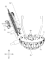
- FIG. 2 is a schematic cross-sectional view taken along the line III-III shown in FIG. 2 as a cutting line.
- Rear perspective view near the second magazine Schematic perspective view of the arm viewed from the upper left direction. Schematic perspective view of the arm viewed from the upper right. Schematic front view of the arm. Top view of the arm. Schematic left side view of the arm. Schematic bottom view of the arm. Enlarged perspective view of a schematic portion of the configuration near the arm.
- the machine tool includes a base 1, a work holding portion 2, an XY moving mechanism 3, a vertical column 4, a Z moving mechanism 5, a first magazine 6, a support portion 7, a second magazine 80, and a tool transfer device 9 (FIGS. 2 and 3).
- a base 1 a work holding portion 2, an XY moving mechanism 3, a vertical column 4, a Z moving mechanism 5, a first magazine 6, a support portion 7, a second magazine 80, and a tool transfer device 9 (FIGS. 2 and 3).
- the spindle head 10 and the like are provided.
- Base 1 forms a rectangular shape in a plan view and extends in the front-back direction.
- a work holding portion 2 is provided on the upper front side of the base 1.
- an XY moving mechanism 3 that can move in the left-right direction (X direction) and the front-back direction (Y direction) is provided on the rear side of the work holding portion 2.
- a vertical pillar 4 is provided on the upper side of the XY movement mechanism 3.
- a Z moving mechanism 5 that can move in the vertical direction (Z direction) is provided on the front surface of the vertical column 4.
- the spindle head 10 is provided in the Z moving mechanism 5.
- the spindle head 10 includes a spindle extending up and down. A tool is attached to the lower end of the spindle.
- the first magazine 6 is provided on the front side of the spindle head 10.
- the first magazine 6 is connected to the vertical column 4 via a connecting member.
- the first magazine 6 includes a disk 6a and an arm 6b.
- a motor (not shown) is connected to the disk 6a, and the disk 6a rotates around its central axis by driving the motor.
- a plurality of arms 6b are radially provided on the peripheral edge of the disk 6a. The arm 6b holds the tool.
- the first magazine 6 is arranged so that the central axis of the disk 6a extends in the front-rear direction and the disk 6a is in a forward leaning posture.
- the lower end position of the first magazine 6 is the tool change position.
- the arm 6b holding the tool is arranged at the tool replacement position, and the Z moving mechanism 5 is moved downward.
- the spindle is equipped with a tool gripped by the arm 6b.
- an empty arm 6b is placed at the tool replacement position, and the Z moving mechanism 5 is moved upward. Based on the upward movement of the Z moving mechanism 5, the arm 6b grips the tool of the spindle, and the tool is removed from the spindle.
- the tool attached to the spindle processes the work held in the work holding part 2.
- the XY moving mechanism 3 adjusts the front-back and left-right positions of the tool (spindle) with respect to the work, and the Z-moving mechanism 5 adjusts the vertical position of the tool.
- the support portion 7 is provided on the rear side of the left portion of the base 1.
- the support portion 7 extends upward, and a second magazine 80 is provided at the tip portion thereof.
- the second magazine 80 is arranged on the left side and the rear side of the first magazine 6.
- the second magazine 80 includes a tool transfer device 9.
- the tool transfer device 9 transfers a tool between the arm 6b of the first magazine 6 and the arm 83 of the second magazine 80.
- the cutting line in FIG. 3 is orthogonal to the central axis of the support disk 81.
- the first magazine 6 includes a cover 6d.
- the cover 6d covers the outside of each arm 6b.
- the cover 6d is rotatable and rotates together with the arm 6b when the tool is exchanged with the spindle, and does not interfere with the tool exchange.
- the mounting member 70 is fixed to the upper end of the support portion 7.
- the mounting member 70 includes a front plate portion 70a, a rear plate portion 70b, and a support cylinder 70c.
- the front plate portion 70a and the rear plate portion 70b extend in the upper right direction from the upper end portion of the support portion 7 and are arranged in the front-rear direction.
- the support cylinder 70c is connected to the upper end portions of the front plate portion 70a and the rear plate portion 70b with the left-right direction as the axial direction.
- the reduction gear device 71 Connect the reduction gear device 71 to the right part of the support cylinder 70c.
- the reduction gear device 71 has an annular inner peripheral portion 72 and an outer peripheral portion 73.
- the inner peripheral portion 72 is fixed to the peripheral portion of the support cylinder 70c.
- the outer peripheral portion 73 is rotatably attached around the inner peripheral portion 72 around the axis. That is, the inner peripheral portion 72 rotatably supports the outer peripheral portion 73.
- the second magazine 80 includes a support disk 81, a motor 82, and an arm 83.
- the support disk 81 constitutes a turntable.
- the motor 82 is connected to the left portion of the support cylinder 70c.
- the support disk 81 is arranged on the right side of the reduction gear device 71 with both sides facing left and right.
- the right side of the support disk 81 faces slightly backward, and the left side faces slightly forward.
- a through hole 81b (see FIG. 3) penetrating to the left and right is provided at the center of the support disk 81.
- the support cylinder 70c and the inner peripheral portion 72 extend in the axial direction and are inserted into the through hole 81b.
- the outer peripheral portion 73 is connected to the left edge portion of the through hole 81b.
- the outer peripheral portion 73 is rotated by the drive of the motor 82, and the support disk 81 is rotated around its central axis 81a.
- the central axis 81a constitutes a
- the arm 6b of the first magazine 6 and the arm 83 of the second magazine 80 are closest to each other at a position below the central axis 81a.
- the closest position is the magazine tool exchange position P for exchanging the tool of the first magazine 6 and the tool of the second magazine 80.
- the arm 6b of the first magazine 6 arranged at the magazine tool replacement position P is referred to as a replacement position arm 6c
- the arm 83 of the second magazine 80 is referred to as a replacement position arm 84.
- a tool is exchanged between the exchange position arm 6c and the exchange position arm 84.
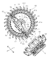
- One end portion 83f of the gripping arm arm 83 projects radially outward from the peripheral edge portion of the support disk 81.
- L1 indicates a line passing through the central axis 81a of the support disk 81 and the center of the tool 50 gripped by the exchange position arm 84
- L2 indicates a line along the longitudinal direction of the exchange position arm 84. ..
- the line L2 passes through the center of the replacement position arm 84.
- the line L1 and the line L2 intersect to form a predetermined angle ⁇ (> 0). Since each arm 83 located at the magazine tool replacement position P is arranged so as to form a predetermined angle ⁇ , the other end 83 g of the arm 83 is not opposed to the central axis 81a of the support disk 81.
- a tool transfer device 9 is provided on the right side of the support disk 81.
- the tool transfer device 9 includes a motor 9a, a ball screw 9b, a nut 9c, a track 9d, a slider 9e, a pot 9f, and a connecting portion 9g.
- the support cylinder 70c and the inner peripheral portion 72 inserted into the through hole 81b support the ball screw 9b and the track 9d.
- the ball screw 9b is connected to the rotation shaft of the motor 9a.
- the nut 9c is connected to the ball screw 9b.
- the track 9d is arranged next to the ball screw 9b.
- the track 9d is fixed at a position deviated from the central axis 81a of the support disk 81.
- the track 9d extends along the longitudinal direction of the replacement position arm 84.
- One end of the track 9d faces the exchange position arm 84.
- the slider 9e is slidably provided on the track 9d.
- the pot 9f is attached to the slider 9e.
- the connecting portion 9g connects the slider 9e and the nut 9c.
- the ball screw 9b is rotated by the drive of the motor 9a, the nut 9c moves along the ball screw 9b, and the slider 9e, the connecting portion 9g, and the pot 9f move along the trajectory 9d.
- the pot 9f grabs the tool 50 gripped by the replacement position arm 84 and passes it to the empty replacement position arm 6c, or grabs the tool 50 gripped by the replacement position arm 6c and passes it to the empty replacement position arm 84.
- a plurality of arms 83 are arranged along the peripheral edge of the support disk 81.
- the arm 83 extends in the radial direction of the support disk 81.
- the configuration of the arm 83 will be described with reference to FIGS. 5 to 13.
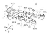
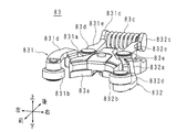
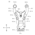
- the arm 83 includes a first support rod 831 and a second support rod 832.
- the support plate 83a, the first support rod 831 and the second support rod 832 extend in the front-rear direction.
- the front end portion of the support plate 83a has a circular arc shape in a plan view protruding to the rear side.
- the first support rod 831 and the second support rod 832 are separated from each other in the left-right direction, and are arranged on the left side and the right side of the support plate 83a, respectively.
- the front-rear midway portion of the first support rod 831 is connected to the front-rear halfway portion of the support plate 83a via a pivot axis 83d whose axial direction is the vertical direction.
- the front-rear midway portion of the second support rod 832 is connected to the front-rear halfway portion of the support plate 83a via a pivot axis 83e whose axial direction is the vertical direction.
- Axis 83d constitutes the first axis.
- Axis 83e constitutes the second axis.
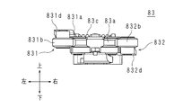
- the front side of the first support rod 831 from the pivot 83d is referred to as a front portion 831d
- the rear side of the pivot rod 83d is referred to as a rear portion 831e
- the front side of the second support rod 832 from the pivot 83e is referred to as a front portion 832d
- the rear side of the pivot rod 83e is referred to as a rear portion 832e.
- the front portion 831d of the first support rod 831 is curved so as to project to the left side.
- the front portion 832d of the second support rod 832 is curved so as to project to the right.
- the front end portion of the arc-shaped support plate 83a is arranged between the front side portions 831d and 832d of the first support rod 831 and the second support rod 832.
- a spring seat 831c is provided at the rear end of the first support rod 831.
- a spring seat 832c is provided at the rear end of the second support rod 832.
- the two spring seats 831c and 832c form a disk shape and face each other in the left-right direction.
- a push spring 83c is provided between the two spring seats 831c and 832c.
- the push spring 83c urges the two spring seats 831c and 832c so that the two spring seats 831c and 832c are separated from each other in the left-right direction.
- the rollers 831b and 832b form one end 83f of the arm 83, and the spring seats 831c, 832c and the push spring 83c form the other end 83g of the arm 83 (see FIG. 3).
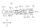
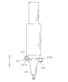
- the front side portion 831d of the first support rod 831 is located on the left side of the rear side portion 831e.
- the inclined portion 831a connects the front side portion 831d and the rear side portion 831e.
- the inclined portion 831a is inclined so as to extend downward from the rear end portion of the front side portion 831d toward the rear side.
- the roller 831b is provided on the lower surface of the front end portion of the front portion 831d.
- the front side portion 831d constitutes the first portion
- the inclined portion 831a constitutes the first inclined portion.
- the roller 831b constitutes the first grip portion.
- the vertical direction is a direction parallel to the rotation axis direction of the tool magazine 80.
- the front side portion 832d of the second support rod 832 is located on the right side of the rear side portion 832e.
- An inclined portion 832a connects the front side portion 832d and the rear side portion 832e.
- the inclined portion 832a is inclined so as to extend upward from the rear end portion of the front side portion 832d toward the rear side.
- the roller 832b is provided on the upper surface of the front end portion of the front side portion 832d.
- the front side portion 832d constitutes the second portion
- the inclined portion 832a constitutes the second inclined portion
- the roller 832b constitutes the second grip portion.
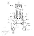
- the first support rod 831 and the second support rod 832 are the same parts, and they are only upside down.
- the positions of the pivot axis 83d and the pivot axis 83e are the same in the direction parallel to the rotation axis direction of the tool magazine 80.
- the inclined directions of the inclined portion 831a and the inclined portion 832a are opposite to each other, and the magnitudes of the inclined portions are the same.
- the lengths of the inclined portion 831a and the inclined portion 832a are the same. Therefore, the positions of the roller 831b and the roller 832b are the same in the direction parallel to the rotation axis direction of the tool magazine.
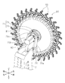
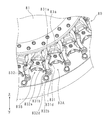
- the plurality of arms 83 are lined up along the peripheral edge of the support disk 81.
- the plurality of arms 83 include a first arm 83A and a second arm 83B located next to the first arm 83A.
- the lower surface of the front side portion 831d of the first arm 83A is located above the upper surface of the front side portion 832d of the second arm 83B.
- the front side portion 831d and the front side portion 832d are separated from each other in the axial direction of the support disk 81.
- the positions of the front side portion 831d of the first arm 83A and the front side portion 832d of the second arm 83B are displaced in the vertical direction, that is, in the axial direction of the support disk 81.
- the first arm 83A and the second arm 83B that is, the two adjacent arms 83 are at least partially in the circumferential direction of the support disk 81.
- the front side portions 831d and 832d overlap in the direction parallel to the central axis 81a, in other words, the positions of the front side portions 831d and 832d are displaced in the axial direction of the support disk 81, so that the two adjacent arms 83 interfere with each other in the circumferential direction. do not do.
- the number of arms 83 that can be installed on the support disk 81 is increased in the radial direction as compared with the case where a plurality of arms 83 are arranged so as not to overlap in the direction parallel to the central axis 81a. You can increase it without doing it.
- the tool 50 is mounted between the first support rod 831 and the front portions 831d and 832d of the second support rod 832.
- the rollers 831b and 832b hold the tool 50 by the urging force of the push spring 83c.
- the positions of the first support rod 831 and the second support rod 832 that is, the positions of both side portions of the arm 83 in the circumferential direction of the central shaft 81a are different in the direction parallel to the central shaft 81a. Therefore, by simply arranging the arms 83 in the circumferential direction of the support disk 81, two adjacent arms 83 can be overlapped in a direction parallel to the central axis 81a. That is, in order to overlap the two adjacent arms 83 in the direction parallel to the central axis 81a, it is not necessary to shift the position of the entire other arm 83 with respect to one arm 83 in the direction parallel to the central axis 81a. It is possible to suppress the increase in size in the direction parallel to.
- the arm 83 passes through the center of the support disk 81 and is arranged so as to intersect the line L1 extending in the radial direction of the central axis 81a. With such an arrangement, at least a part of each of the two adjacent arms 83 tends to overlap.
- the first support rod 831 of one arm 83 and the second support rod 832 of the other arm 83 overlap with each other. Therefore, it is possible to suppress the interference between the arms 83 and the increase in size in the direction parallel to the central axis 81a.
- the rollers 831b and 832b are examples of gripping portions, and hemispherical bodies, pins, or plungers may be used instead of the rollers.
- the push spring 83c is an example of the urging member, and rubber may be used instead of the push spring 83c.
- An urging member may be provided between the front portions 831d and 832d, and in this case, a pull spring may be used as the urging member.
- the arms 83 may be arranged so that the positions of the two adjacent arms 83 are displaced from each other in the radial direction of the support disk 81. Also in the first magazine 6, the configuration of the first magazine 6 is the same as that of the second magazine 80 in order to prevent the arms 6b from interfering with each other and to suppress the increase in size in the direction parallel to the central axis of the disk 6a. It may be configured.
- Tool transfer device 50 Tool 80 Second magazine (tool magazine) 81 Support disk (rotary disk) 81a Central axis (rotary axis) 83 Arm 83f One end 83g The other end 831 First support rod 832 Second support rod 9 Tool transfer device
Landscapes
- Engineering & Computer Science (AREA)
- Mechanical Engineering (AREA)
- Automatic Tool Replacement In Machine Tools (AREA)
Abstract
工具を収納するアーム同士の干渉を抑制し、且つ回転軸に平行な方向に大型化することを抑制できるアーム、工具マガジンと工作機械を提供する。 アームは工作機械の工具マガジンに設けてあり、工具を把持する。アームは、工具マガジンに固定する支持板と、該支持板の両側にて回転する二つの支持桿とを備え、前記工具マガジンの回転中心軸方向における前記二つの支持桿の工具把持側端部の位置は異なる。
Description
本技術は工具を把持するアーム、該アームを備える工具マガジン及び該工具マガジンを備える工作機械に関する。
従来、工作機械は工具マガジンを備え、工具マガジンは、大径工具用アームと、小径工具用アームとを有する。大径工具用アームと小径工具用アームは隣合う。工具マガジンの回転軸に平行な方向において、大径工具用アームの位置と、小径工具用アームの位置とは異なる。故に大径工具用アームと小径工具用アームとの干渉を防止できる(例えば特許文献1参照)。
大径工具用アーム又は小径工具用アームは前記回転軸に平行な方向に突出し、段違いである。故に工具マガジンは回転軸に平行な方向に大型化する。
本開示はアーム同士の干渉を抑制し、且つ回転軸に平行な方向に大型化することを抑制するアーム、アームを備える工具マガジン及び工作機械を提供することを目的とする。
本開示のアームは工作機械の工具マガジンに設け、且つ工具を把持するアームにおいて、工具マガジンに固定する支持板と、該支持板の両側にて回転する二つの支持桿とを備え、前記工具マガジンの回転軸方向における前記二つの支持桿の工具把持側端部の位置は異なる。
故に隣合う二つのアームは回転軸に平行な方向に重ねることができる。作業者は一方のアームに対する他方のアーム全体の位置を、回転軸に平行な方向にずらす必要がない。
本開示のアームは、前記回転中心軸方向にて、一方の前記支持桿の工具把持側端部と他方の前記支持桿の工具把持側端部は離れる。
隣合う二つのアームにおいて、一方のアームにおける一方の支持桿の工具把持側端部と他方のアームにおける他方の支持桿の工具把持側端部が回転軸方向に重ならない。
本開示のアームの一方の前記支持桿は、前記工具マガジンの回転軸に直交する方向に延びる第一部分と、該第一部分の一端部から前記回転軸に平行な一方向に向けて延びる第一傾斜部と、前記第一部分の他端部における前記一方向と同じ側に設けてあり、工具を把持する第一把持部とを有し、他方の前記支持桿は、前記回転軸に直交する方向に延びる第二部分と、該第二部分の一端部から回転軸に平行な他方向に向けて延びる第二傾斜部と、前記第二部分の他端部における前記他方向と同じ側に固定してあり、工具を把持する第二把持部とを有し、前記回転軸方向にて、前記第一把持部及び第二把持部は同じ位置にある。
本開示のアームは回転軸方向において、第一傾斜部と第二傾斜部が延びる方向が反対であり、第一把持部と第二把持部の固定位置が反対であるので、第一把持部と第二把持部の固定位置は同じ位置になる。アームは同一の支持桿を互いに反対向きに配置する構成のため、別々に支持桿を作成する必要がなく、部品管理が容易である。
本開示のアームの一方の前記支持桿は、前記回転軸に平行な方向に延びる第一枢軸を備え、前記第一枢軸に前記第一傾斜部は連結し、他方の前記支持桿は前記回転軸に平行な方向に延びる第二枢軸を備え、前記第二枢軸に前記第二傾斜部は連結し、前記回転軸に平行な方向における前記第一枢軸と第二枢軸の位置は同じであり、前記第一傾斜部と第二傾斜部の傾斜角の大きさは同じであり、前記第一傾斜部と第二傾斜部の長さは同じである。
本開示のアームは回転軸方向において、第一傾斜部と第二傾斜部が延びる方向が反対であり、第一把持部と第二把持部の固定位置が反対であるので、第一把持部と第二把持部の固定位置は同じ位置になる。アームは同一の支持桿を互いに反対向きに配置する構成のため、別々に支持桿を作成する必要がなく、部品管理が容易である。
本開示のアームは、前記第一把持部と第二把持部を閉じる方向に付勢する付勢部材を前記二つの支持桿の間に設ける。
本開示のアームは付勢部材の付勢力によって工具を把持する。
本開示の工具マガジンは上記アームを備え、前記アームの一端部は前記回転盤の回転軸に交差する方向にて前記回転盤の周縁部から外向きに突出し、前記アームの長手方向にて前記アームの他端部は前記回転盤の回転軸に非対向となる位置に配置する。
本開示のアームは、回転盤の中心を通り、回転軸の径方向に延びた線に対して交差するように配置する。故に隣合う二つのアーム夫々の少なくとも一部は重なり易い。
本開示の工作機械は上記工具マガジンを備える。
本開示の工作機械は上記アーム及び工具マガジンと同様な作用効果を生じる。
本開示のアーム、工具マガジン及び工作機械は、工具マガジンの回転軸方向における二つの支持桿の工具把持側端部の位置は異なる。故に工具マガジンの周方向にアームを並べるだけで、隣合う二つのアームは回転軸に平行な方向に重なる。一方のアームに対する他方のアーム全体の位置を回転軸に平行な方向にずらす必要はない。故に工具マガジンは回転軸に平行な方向に大型化することを抑制できる。
以下本発明の工作機械について図面に基づいて説明する。以下の説明では、図に示す上下前後左右を使用する。
工作機械は、基台1、ワーク保持部2、XY移動機構3、立柱4、Z移動機構5、第一マガジン6、支持部7、第二マガジン80、工具搬送装置9(図2、図3参照)、主軸ヘッド10等を備える。
基台1は平面視矩形をなし、前後方向に延びる。基台1の上部前側にワーク保持部2を設ける。基台1の上部にて、ワーク保持部2の後側に左右方向(X方向)と前後方向(Y方向)に移動可能なXY移動機構3を設ける。
XY移動機構3の上側に立柱4を設ける。立柱4の前面に上下方向(Z方向)に移動可能なZ移動機構5を設ける。Z移動機構5に主軸ヘッド10を設ける。主軸ヘッド10は上下に延びる主軸を備える。主軸の下端部は工具を装着する。
主軸ヘッド10の前側に第一マガジン6を設ける。第一マガジン6は立柱4に連結部材を介して連結する。第一マガジン6は円盤6aとアーム6bを備える。円盤6aにモータ(図示略)を連結し、円盤6aはモータの駆動によって、その中心軸回りに回転する。円盤6aの周縁部に複数のアーム6bを放射状に設ける。アーム6bは工具を保持する。
円盤6aの中心軸が前後方向に延び且つ円盤6aが前傾姿勢となるように、第一マガジン6を配置する。第一マガジン6の下端位置は工具交換位置である。主軸に工具を装着する場合、工具交換位置に工具を把持したアーム6bを配置し、Z移動機構5を下方に移動する。Z移動機構5の下方移動に基づき、主軸はアーム6bが把持する工具を装着する。主軸から工具を取り外す場合、工具交換位置に空のアーム6bを配置し、Z移動機構5を上方に移動する。Z移動機構5の上方移動に基づき、アーム6bは主軸の工具を把持し、工具は主軸から抜ける。
主軸に装着した工具はワーク保持部2に保持したワークを加工する。XY移動機構3はワークに対する工具(主軸)の前後左右位置を調整し、Z移動機構5は工具の上下位置を調整する。
支持部7は基台1の左部後側に設ける。支持部7は上側に延び、その先端部に第二マガジン80を設ける。第二マガジン80は第一マガジン6の左側且つ後側に配置する。第二マガジン80は工具搬送装置9を備える。工具搬送装置9は、第一マガジン6のアーム6bと第二マガジン80のアーム83との間で、工具の受け渡しを行う。
図3の切断線は支持円盤81の中心軸に直交する。第一マガジン6はカバー6dを備える。カバー6dは各アーム6bの外側を覆う。カバー6dは回転可能であり、主軸との工具交換時にアーム6bと共に回転し、工具交換を妨げない。
図4の如く、支持部7の上端部に取付部材70を固定する。取付部材70は、前板部70a、後板部70b及び支持筒70cを備える。前板部70aと後板部70bは支持部7の上端部から右上方向に延び、且つ前後に並ぶ。支持筒70cは左右方向を軸方向とし、前板部70a及び後板部70bの上端部に連結する。
支持筒70cの右部に減速ギア装置71を連結する。減速ギア装置71は、環状の内周部72と外周部73を有する。内周部72は支持筒70cの周縁部に固定する。外周部73は内周部72の周囲に、軸回りに回転可能に取り付ける。即ち内周部72は外周部73を回転可能に支持する。
第二マガジン80は、支持円盤81、モータ82及びアーム83を備える。支持円盤81は回転盤を構成する。モータ82は支持筒70cの左部に連結する。支持円盤81は両面を左右に向けて、減速ギア装置71の右側に配置する。支持円盤81の右面は若干後側に向き、左面は若干前側を向く。支持円盤81の中央部に、左右に貫通した貫通穴81b(図3参照)を設ける。支持筒70cと内周部72は軸方向に延び、貫通穴81bに挿入する。外周部73は貫通穴81bの左側縁部に連結する。モータ82の駆動によって外周部73は回転し、支持円盤81はその中心軸81a回りに回転する。中心軸81aは回転軸を構成し、水平方向に延びる。
図1の如く、第一マガジン6のアーム6bと、第二マガジン80のアーム83とは、中心軸81aよりも下側の位置にて、最も接近する。該最も接近した位置が第一マガジン6の工具と第二マガジン80の工具を交換するマガジン工具交換位置Pとなる。以下、マガジン工具交換位置Pに配した第一マガジン6のアーム6bを交換位置アーム6cと称し、第二マガジン80のアーム83を交換位置アーム84と称する。交換位置アーム6c及び交換位置アーム84の間で工具交換を行う。
把持アームアーム83の一端部83fは、支持円盤81の周縁部から径方向外向きに突出する。図3において、L1は、支持円盤81の中心軸81aと、交換位置アーム84が把持する工具50の中心とを通る線を示し、L2は、交換位置アーム84の長手方向に沿った線を示す。線L2は、交換位置アーム84の中央を通る。線L1と線L2は交差し、所定角度θ(>0)を形成する。マガジン工具交換位置Pに位置する各アーム83について所定角度θを形成するように配置するので、アーム83の他端部83gは支持円盤81の中心軸81aに非対向となる。
支持円盤81の右側に工具搬送装置9を設ける。工具搬送装置9は、モータ9a、ボール螺子9b、ナット9c、軌道9d、スライダ9e、ポット9f、連結部9gを備える。貫通穴81bに挿入した支持筒70cと内周部72はボール螺子9bと軌道9dを支持する。ボール螺子9bはモータ9aの回転軸に連結する。ナット9cはボール螺子9bに連結する。
図3の如く、軌道9dはボールねじ9bの隣に配置する。軌道9dは支持円盤81の中心軸81aから外れた位置に固定する。軌道9dは、交換位置アーム84の長手方向に沿って延びる。軌道9dの一端部は交換位置アーム84に臨む。スライダ9eは軌道9dに摺動可能に設ける。ポット9fはスライダ9eに取り付ける。連結部9gは、スライダ9eとナット9cを連結する。モータ9aの駆動によってボール螺子9bが回転し、ナット9cがボール螺子9bに沿って移動し、スライダ9e、連結部9g及びポット9fが軌道9dに沿って移動する。ポット9fは、交換位置アーム84が把持する工具50を掴み、空の交換位置アーム6cに渡す、又は交換位置アーム6cが把持する工具50を掴み、空の交換位置アーム84に渡す。
図3及び図4の如く、複数のアーム83は支持円盤81の周縁部に沿って並ぶ。アーム83は支持円盤81の径方向に延びる。以下、アーム83の構成について図5~図13を用いて説明する。
アーム83は、第一支持桿831と第二支持桿832を備える。支持板83a、第一支持桿831及び第二支持桿832は前後方向に延びる。支持板83aの前端部は後側に突出した平面視円弧状をなす。
第一支持桿831と第二支持桿832は左右方向に離れ、支持板83aの左側と右側に夫々配置する。
第一支持桿831の前後方向中途部は、上下方向を軸方向とした枢軸83dを介して、支持板83aの前後方向中途部に連結する。第二支持桿832の前後方向中途部は、上下方向を軸方向とした枢軸83eを介して、支持板83aの前後方向中途部に連結する。枢軸83dは第一枢軸を構成する。枢軸83eは第二枢軸を構成する。
第一支持桿831の枢軸83dよりも前側を前側部分831dと称し、枢軸83dよりも後側を後側部分831eと称す。第二支持桿832の枢軸83eよりも前側を前側部分832dと称し、枢軸83eよりも後側を後側部分832eと称す。第一支持桿831の前側部分831dは左側に突出するように湾曲する。第二支持桿832の前側部分832dは右側に突出するように湾曲する。円弧状をなす支持板83aの前端部は、第一支持桿831及び第二支持桿832の前側部分831d、832dの間に配置してある。
第一支持桿831の後端部にバネ座831cを設ける。第二支持桿832の後端部にバネ座832cを設ける。二つのバネ座831c、832cは円板状をなし、左右方向に対向する。二つのバネ座831c、832cの間に押しばね83cを設ける。押しばね83cは二つのバネ座831c、832cを二つのバネ座831c、832cが左右方向にて相互に離れるように付勢する。ローラ831b、832bはアーム83の一端部83fを構成し、バネ座831c、832c及び押しばね83cはアーム83の他端部83gを構成する(図3参照)。
第一支持桿831の前側部分831dは後側部分831eよりも左側に位置する。前側部分831dと後側部分831eを傾斜部831aが連結する。傾斜部831aは前側部分831dの後端部から後側に向かうに従って、下側に向かって延びるように傾斜する。ローラ831bは前側の部分831dの前端部下面に設ける。前側部分831dは第一部分を構成し、傾斜部831aは第一傾斜部を構成する。ローラ831bは第一把持部を構成する。上下方向は、工具マガジン80の回転軸方向に平行な方向である。
第二支持桿832の前側部分832dは後側部分832eよりも右側に位置する。前側部分832dと後側部分832eは傾斜部832aが連結する。傾斜部832aは前側部分832dの後端部から後側に向かうに従って、上側に延びるように傾斜する。ローラ832bは前側部分832dの前端部上面に設ける。前側部分832dは第二部分を構成し、傾斜部832aは第二傾斜部を構成し、ローラ832bは第二把持部を構成する。
第一支持桿831と第二支持桿832は同一部品であり、上下が反対になっているのみである。工具マガジン80の回転軸方向に平行な方向において、枢軸83dと枢軸83eの位置は同じである。傾斜部831aと傾斜部832aの傾斜方向は逆であり、傾斜角の大きさは同じである。傾斜部831aと傾斜部832aの長さは同じである。故に工具マガジンの回転軸方向に平行な方向において、ローラ831bとローラ832bの位置は同じである。
複数のアーム83は支持円盤81の周縁部に沿って並ぶ。複数のアーム83は、第一アーム83Aと、該第一アーム83Aの隣に位置する第二アーム83Bを含む。第一アーム83Aの前側部分831dの下面は第二アーム83Bの前側部分832dの上面よりも上側に位置する。前側部分831dと前側部分832dは支持円盤81の軸方向に離れる。即ち隣合う第一アーム83A第二アーム83Bにおいて、第一アーム83Aの前側部分831d、及び第二アーム83Bの前側の部分832dの位置は、上下方向、即ち支持円盤81の軸方向にずれる。
前述の如く、線L1と線L2は交差し、所定角度θを形成するので、第一アーム83Aと第二アーム83B、即ち隣合う二つのアーム83は支持円盤81の周方向にて、少なくとも部分的に同じ位置にある。しかし前側部分831d、832dは中心軸81aに平行な方向に重なる、換言すれば前側部分831d、832dの位置は支持円盤81の軸方向にずれるので、周方向にて隣合う二つのアーム83は干渉しない。
上記工作機械は、中心軸81aに平行な方向に重ならないように複数のアーム83を配置する場合に比べて、支持円盤81に設置可能なアーム83の数を支持円盤81を径方向に大型化することなく、増やすことができる。
工具50は第一支持桿831と第二支持桿832の前側の部分831d、832dの間に装着する。ローラ831b、832bは、押しばね83cの付勢力によって、工具50を保持する。
実施形態の工作機械は中心軸81aに平行な方向において、第一支持桿831と第二支持桿832の位置、即ち中心軸81aの周方向におけるアーム83の両側部分の位置が異なる。故に支持円盤81の周方向にアーム83を並べるだけで、隣合う二つのアーム83を中心軸81aに平行な方向に重ねることができる。即ち中心軸81aに平行な方向において、隣合う二つのアーム83を重ねる為に、一方のアーム83に対する他方のアーム83全体の位置を中心軸81aに平行な方向にずらす必要はなく、中心軸81aに平行な方向に大型化することを抑制できる。
アーム83は、支持円盤81の中心を通り、中心軸81aの径方向に延びた線L1に対して交差するように配置する。このような配置にすることによって、隣合う二つのアーム83夫々の少なくとも一部は重なり易くなる。
また一方のアーム83の第一支持桿831と、他方のアーム83の第二支持桿832とが重なる。故にアーム83同士の干渉と、中心軸81aに平行な方向への大型化の抑制を実現する。
ローラ831b、832bは把持部の一例であり、ローラに代えて、半球状体、ピン、またはプランジャーを使用してもよい。押しばね83cは付勢部材の一例であり、押しばね83cに代えて、ゴムを使用してもよい。前側の部分831d、832dの間に付勢部材を設けてもよく、この場合、引きばねを付勢部材として使用してもよい。
支持円盤81の径方向において、隣合う二つのアーム83の位置が互いにずれるようにアーム83を配置してもよい。第一マガジン6においても、アーム6b同士が干渉せず、且つ円盤6aの中心軸に平行な方向への大型化の抑制を実現すべく、第一マガジン6の構成を第二マガジン80と同様な構成にしてもよい。
50 工具
80 第二マガジン(工具マガジン)
81 支持円盤(回転盤)
81a 中心軸(回転軸)
83 アーム
83f 一端部
83g 他端部
831 第一支持桿
832 第二支持桿
9 工具搬送装置
80 第二マガジン(工具マガジン)
81 支持円盤(回転盤)
81a 中心軸(回転軸)
83 アーム
83f 一端部
83g 他端部
831 第一支持桿
832 第二支持桿
9 工具搬送装置
Claims (7)
- 工作機械の工具マガジンに設け、工具を把持するアームにおいて、
工具マガジンに固定する支持板と、
該支持板の両側にて回転する二つの支持桿と
を備え、
前記工具マガジンの回転中心の軸である回転中心軸方向における前記二つの支持桿の工具把持側端部の位置は異なる
アーム。 - 前記回転中心軸方向にて、一方の前記支持桿の工具把持側端部と他方の前記支持桿の工具把持側端部は離れる
請求項1に記載のアーム。 - 一方の前記支持桿は、
前記工具マガジンの回転中心軸に直交する方向に延びる第一部分と、
該第一部分の一端部から前記回転中心軸に平行な一方向に向けて延びる第一傾斜部と、
前記第一部分の他端部における前記一方向と同じ側に設けてあり、工具を把持する第一把持部と
を有し、
他方の前記支持桿は、
前記回転中心軸に直交する方向に延びる第二部分と、
該第二部分の一端部から前記回転中心軸に平行な他方向に向けて延びる第二傾斜部と、
前記第二部分の他端部における前記他方向と同じ側に固定してあり、工具を把持する第二把持部と
を有し、
前記回転中心軸方向にて、前記第一把持部と第二把持部は同じ位置にある
請求項1又は2に記載のアーム。 - 一方の前記支持桿は前記回転中心軸に平行な方向に延びる第一枢軸を備え、
前記第一枢軸に前記第一傾斜部は連結し、
他方の前記支持桿は前記回転中心軸に平行な方向に延びる第二枢軸を備え、
前記第二枢軸に前記第二傾斜部は連結し、
前記回転中心軸に平行な方向における前記第一枢軸と第二枢軸の位置は同じであり、
前記第一傾斜部と第二傾斜部の傾斜角の大きさは同じであり、
前記第一傾斜部と第二傾斜部の長さは同じである
請求項3に記載のアーム。 - 前記第一把持部と第二把持部を閉じる方向に付勢する付勢部材を前記二つの支持桿の間に設ける
請求項4に記載のアーム。 - 回転盤に設けた請求項1から5のいずれか一つに記載のアームを備え、
前記アームの一端部は前記回転盤の回転中心軸に交差する方向にて、前記回転盤の周縁部から外向きに突出し、
前記アームの長手方向にて、前記アームの他端部は前記回転盤の回転軸に非対向となる位置に配置する
工具マガジン。 - 請求項6に記載の工具マガジンを備える工作機械。
Priority Applications (4)
| Application Number | Priority Date | Filing Date | Title |
|---|---|---|---|
| CN202180044852.9A CN115916456A (zh) | 2020-06-30 | 2021-06-22 | 臂、刀库和机床 |
| DE112021002402.7T DE112021002402T5 (de) | 2020-06-30 | 2021-06-22 | Arm, werkzeugmagazin und werkzeugmaschine |
| JP2022533888A JPWO2022004484A1 (ja) | 2020-06-30 | 2021-06-22 | |
| US18/072,861 US20230090074A1 (en) | 2020-06-30 | 2022-12-01 | Arm, tool magazine, and machine tool |
Applications Claiming Priority (2)
| Application Number | Priority Date | Filing Date | Title |
|---|---|---|---|
| JP2020-113512 | 2020-06-30 | ||
| JP2020113512 | 2020-06-30 |
Related Child Applications (1)
| Application Number | Title | Priority Date | Filing Date |
|---|---|---|---|
| US18/072,861 Continuation US20230090074A1 (en) | 2020-06-30 | 2022-12-01 | Arm, tool magazine, and machine tool |
Publications (1)
| Publication Number | Publication Date |
|---|---|
| WO2022004484A1 true WO2022004484A1 (ja) | 2022-01-06 |
Family
ID=79316156
Family Applications (1)
| Application Number | Title | Priority Date | Filing Date |
|---|---|---|---|
| PCT/JP2021/023564 WO2022004484A1 (ja) | 2020-06-30 | 2021-06-22 | アーム、工具マガジン及び工作機械 |
Country Status (5)
| Country | Link |
|---|---|
| US (1) | US20230090074A1 (ja) |
| JP (1) | JPWO2022004484A1 (ja) |
| CN (1) | CN115916456A (ja) |
| DE (1) | DE112021002402T5 (ja) |
| WO (1) | WO2022004484A1 (ja) |
Citations (5)
| Publication number | Priority date | Publication date | Assignee | Title |
|---|---|---|---|---|
| JPS63144928A (ja) * | 1986-12-08 | 1988-06-17 | Honda Motor Co Ltd | 自動工具交換装置における工具クランバ開閉装置 |
| JPH0794846A (ja) * | 1993-09-20 | 1995-04-07 | Pioneer Electron Corp | Pcb加工機 |
| JP2005271179A (ja) * | 2004-03-26 | 2005-10-06 | Brother Ind Ltd | 工作機械の工具交換装置 |
| JP2011020211A (ja) * | 2009-07-15 | 2011-02-03 | Okuma Corp | 工具マガジン |
| US20150166202A1 (en) * | 2013-12-18 | 2015-06-18 | Airbus Ds Gmbh | Apparatus for Processing a Structure as well as Spacecraft |
-
2021
- 2021-06-22 WO PCT/JP2021/023564 patent/WO2022004484A1/ja active Application Filing
- 2021-06-22 CN CN202180044852.9A patent/CN115916456A/zh active Pending
- 2021-06-22 JP JP2022533888A patent/JPWO2022004484A1/ja active Pending
- 2021-06-22 DE DE112021002402.7T patent/DE112021002402T5/de active Pending
-
2022
- 2022-12-01 US US18/072,861 patent/US20230090074A1/en active Pending
Patent Citations (5)
| Publication number | Priority date | Publication date | Assignee | Title |
|---|---|---|---|---|
| JPS63144928A (ja) * | 1986-12-08 | 1988-06-17 | Honda Motor Co Ltd | 自動工具交換装置における工具クランバ開閉装置 |
| JPH0794846A (ja) * | 1993-09-20 | 1995-04-07 | Pioneer Electron Corp | Pcb加工機 |
| JP2005271179A (ja) * | 2004-03-26 | 2005-10-06 | Brother Ind Ltd | 工作機械の工具交換装置 |
| JP2011020211A (ja) * | 2009-07-15 | 2011-02-03 | Okuma Corp | 工具マガジン |
| US20150166202A1 (en) * | 2013-12-18 | 2015-06-18 | Airbus Ds Gmbh | Apparatus for Processing a Structure as well as Spacecraft |
Also Published As
| Publication number | Publication date |
|---|---|
| CN115916456A (zh) | 2023-04-04 |
| JPWO2022004484A1 (ja) | 2022-01-06 |
| DE112021002402T5 (de) | 2023-02-16 |
| US20230090074A1 (en) | 2023-03-23 |
Similar Documents
| Publication | Publication Date | Title |
|---|---|---|
| JP5429221B2 (ja) | 工具交換装置、及び工具交換装置を備える工作機械 | |
| JP5949182B2 (ja) | 工作機械 | |
| JP5806310B2 (ja) | ワーク支持装置 | |
| US10166639B2 (en) | System for changing and inserting tools into or presenting tools at a machine tool and tool magazine, also machine tool having a tool changing system or tool magazine | |
| JP5722534B2 (ja) | 複数のワークピーススピンドルを備えた多軸旋盤 | |
| JP5497582B2 (ja) | 横型マシニングセンタ | |
| JP4845484B2 (ja) | 工具交換装置 | |
| JP6807669B2 (ja) | 工作機械ユニット | |
| JP3877560B2 (ja) | 自動工具交換装置 | |
| JP2010064243A6 (ja) | 複数のワークピーススピンドルを備えた多軸旋盤 | |
| WO2022004484A1 (ja) | アーム、工具マガジン及び工作機械 | |
| JP5385036B2 (ja) | 工具マガジン | |
| JP2009538743A (ja) | 工作機械 | |
| CN220516231U (zh) | 一种刀库断刀检测机构 | |
| WO2022004485A1 (ja) | 工具交換装置と工作機械 | |
| JP2018034259A (ja) | 工作機械 | |
| JP2011212785A (ja) | 工作機械 | |
| JP7049236B2 (ja) | 工具交換装置 | |
| JP3233444U (ja) | 工具マガジン及び工作機械 | |
| JP5065799B2 (ja) | 立型工作機械 | |
| JP4272759B2 (ja) | 加工ヘッド装置 | |
| JP4501299B2 (ja) | パンチプレス | |
| JP6476537B2 (ja) | 工作機械及び工具ホルダ | |
| JP6760183B2 (ja) | 把持アーム及び工作機械 | |
| CN114952364B (zh) | 刀库和机床 |
Legal Events
| Date | Code | Title | Description |
|---|---|---|---|
| 121 | Ep: the epo has been informed by wipo that ep was designated in this application |
Ref document number: 21831577 Country of ref document: EP Kind code of ref document: A1 |
|
| ENP | Entry into the national phase |
Ref document number: 2022533888 Country of ref document: JP Kind code of ref document: A |
|
| 122 | Ep: pct application non-entry in european phase |
Ref document number: 21831577 Country of ref document: EP Kind code of ref document: A1 |