WO2021251051A1 - スリッタ - Google Patents
スリッタ Download PDFInfo
- Publication number
- WO2021251051A1 WO2021251051A1 PCT/JP2021/018128 JP2021018128W WO2021251051A1 WO 2021251051 A1 WO2021251051 A1 WO 2021251051A1 JP 2021018128 W JP2021018128 W JP 2021018128W WO 2021251051 A1 WO2021251051 A1 WO 2021251051A1
- Authority
- WO
- WIPO (PCT)
- Prior art keywords
- winding
- product
- winding core
- take
- shaft
- Prior art date
- Legal status (The legal status is an assumption and is not a legal conclusion. Google has not performed a legal analysis and makes no representation as to the accuracy of the status listed.)
- Ceased
Links
Images







Classifications
-
- B—PERFORMING OPERATIONS; TRANSPORTING
- B65—CONVEYING; PACKING; STORING; HANDLING THIN OR FILAMENTARY MATERIAL
- B65H—HANDLING THIN OR FILAMENTARY MATERIAL, e.g. SHEETS, WEBS, CABLES
- B65H19/00—Changing the web roll
- B65H19/22—Changing the web roll in winding mechanisms or in connection with winding operations
- B65H19/30—Lifting, transporting, or removing the web roll; Inserting core
-
- B—PERFORMING OPERATIONS; TRANSPORTING
- B65—CONVEYING; PACKING; STORING; HANDLING THIN OR FILAMENTARY MATERIAL
- B65H—HANDLING THIN OR FILAMENTARY MATERIAL, e.g. SHEETS, WEBS, CABLES
- B65H18/00—Winding webs
- B65H18/02—Supporting web roll
- B65H18/04—Interior-supporting
-
- B—PERFORMING OPERATIONS; TRANSPORTING
- B65—CONVEYING; PACKING; STORING; HANDLING THIN OR FILAMENTARY MATERIAL
- B65H—HANDLING THIN OR FILAMENTARY MATERIAL, e.g. SHEETS, WEBS, CABLES
- B65H19/00—Changing the web roll
- B65H19/10—Changing the web roll in unwinding mechanisms or in connection with unwinding operations
- B65H19/12—Lifting, transporting, or inserting the web roll; Removing empty core
-
- B—PERFORMING OPERATIONS; TRANSPORTING
- B65—CONVEYING; PACKING; STORING; HANDLING THIN OR FILAMENTARY MATERIAL
- B65H—HANDLING THIN OR FILAMENTARY MATERIAL, e.g. SHEETS, WEBS, CABLES
- B65H19/00—Changing the web roll
- B65H19/22—Changing the web roll in winding mechanisms or in connection with winding operations
- B65H19/2207—Changing the web roll in winding mechanisms or in connection with winding operations the web roll being driven by a winding mechanism of the centre or core drive type
- B65H19/2215—Turret-type with two roll supports
-
- B—PERFORMING OPERATIONS; TRANSPORTING
- B65—CONVEYING; PACKING; STORING; HANDLING THIN OR FILAMENTARY MATERIAL
- B65H—HANDLING THIN OR FILAMENTARY MATERIAL, e.g. SHEETS, WEBS, CABLES
- B65H19/00—Changing the web roll
- B65H19/22—Changing the web roll in winding mechanisms or in connection with winding operations
- B65H19/28—Attaching the leading end of the web to the replacement web-roll core or spindle
- B65H19/283—Attaching the leading end of the web to the replacement web-roll core or spindle by applying adhesive to the core
-
- B—PERFORMING OPERATIONS; TRANSPORTING
- B65—CONVEYING; PACKING; STORING; HANDLING THIN OR FILAMENTARY MATERIAL
- B65H—HANDLING THIN OR FILAMENTARY MATERIAL, e.g. SHEETS, WEBS, CABLES
- B65H75/00—Storing webs, tapes, or filamentary material, e.g. on reels
- B65H75/02—Cores, formers, supports, or holders for coiled, wound, or folded material, e.g. reels, spindles, bobbins, cop tubes, cans, mandrels or chucks
-
- B—PERFORMING OPERATIONS; TRANSPORTING
- B65—CONVEYING; PACKING; STORING; HANDLING THIN OR FILAMENTARY MATERIAL
- B65H—HANDLING THIN OR FILAMENTARY MATERIAL, e.g. SHEETS, WEBS, CABLES
- B65H2301/00—Handling processes for sheets or webs
- B65H2301/50—Auxiliary process performed during handling process
- B65H2301/51—Modifying a characteristic of handled material
- B65H2301/516—Securing handled material to another material
- B65H2301/5163—Applying label, tab to handled material
Definitions
- the present invention relates to a slitter in which a web having a narrow slit is wound around a winding core attached to a winding shaft, and the wound winding product is carried out.
- a device called a slitter is used to obtain this take-up product.
- a slitter is a device in which a wide web to be transferred is slit into a narrow width with a cutter, and then the narrow web is wound around a winding core mounted on a winding shaft to obtain a winding product.
- the worker In the conventional slitter as described above, the worker usually manually attaches the winding core to the winding shaft and removes the winding product, and every time the winding core is full, the work is performed. It was necessary for the staff to pull out the wound product and install a new winding core. When such manual work is performed, the load of the product is applied to the worker when the wound product is pulled out, which increases the work load, and in addition, the slitter is used during the installation of the winding core and the removal of the wound product. There was a problem that it was necessary to stop it and the operating rate decreased.
- Patent Document 1 a slitter winding product unloading device that can remove the wound product from the winding shaft without manual work. According to this device, after the take-up product is taken out from the take-up shaft, the winding core can be quickly attached to the take-up shaft, which is the next process, and the work load on the worker can be reduced. It is possible to improve the operating rate.
- the device of Patent Document 1 can reduce the work load of the worker, the work of attaching the winding core by the worker is still necessary. For this reason, the slitter had to be stopped and the work could not be resumed until the worker attached a new winding core and the worker started the next winding. In this case, if the stop time of the slitter is to be shortened, the worker must work frequently, and the device of Patent Document 1 does not require the manual work of the worker.
- the present invention has been made in view of the above problems, and by enabling automation of a series of processes and eliminating manual work by workers, it is possible to eliminate a decrease in operating rate and a work load on workers.
- the purpose is to provide.
- the slitter of the present invention carries out a winding device in which a web slit in a narrow width is wound around a winding core mounted on a winding shaft to obtain a winding product, and the winding product is carried out.
- the product taking-out device and a working device that receives the winding core from a supplier and delivers it to the winding device, and receives the winding product from the winding device, and the working device supplies the winding core. It is provided with a winding core preparing means for receiving the winding core from the beginning and a winding product transfer means for transferring the winding product received from the winding device to the product taking-out device side.
- the arrangement of the working apparatus includes an arrangement in which the winding core preparing means can receive the winding core from the source of the winding core, and an arrangement in which the winding product transfer means can receive the winding product.
- the slitter of the present invention by switching the arrangement of the working device, it is possible to continuously supply the winding core to the winding device and carry out the winding product. For this reason, by appropriately automating the winding to the winding core in the winding device, the slitter can supply the winding core to the winding device, wind it to the winding core in the winding device, and carry out the wound product. It enables automation of a series of processes. As a result, in a series of steps of the slitter, the manual work of the worker can be omitted, so that the decrease in the operating rate of the slitter and the work load of the worker due to the manual work of the worker can be eliminated.
- the slitter of the present invention preferably has the following configurations.
- the take-up device is a turret type equipped with a pair of the take-up shafts, and the take-up device mounted on the other take-up shaft while the web is taken up on one of the take-up shafts. It is preferable that the product is received by the winding product transfer means and the winding core received by the winding core preparing means is passed to the other winding shaft. According to this configuration, preparations for a new winding work proceed without interrupting the winding work, so that the work becomes efficient.
- the work device can be swiveled around a swivel axis, and the switching of the arrangement of the work device is due to the swivel of the work device and the movement in the plane direction. Is preferable. According to this configuration, it is possible to switch the arrangement of working devices without complicating the structure.
- the winding core preparing means is a shaft into which the winding core can be inserted. According to this configuration, the winding core can be delivered with a simple structure.
- the take-up product transfer means is a shaft into which the take-up product can be inserted. According to this configuration, the wound product can be delivered with a simple structure.
- the winding core preparing means is provided with an adhesive material attaching device for attaching the adhesive material to the winding core.
- an adhesive material attaching device for attaching the adhesive material to the winding core.
- the effect of the present invention is as described above, and by switching the arrangement of the working device, it is possible to continuously supply the winding core to the winding device and carry out the winding product. For this reason, by appropriately automating the winding to the winding core in the winding device, the slitter can supply the winding core to the winding device, wind it to the winding core in the winding device, and carry out the wound product. It enables automation of a series of processes. As a result, in a series of steps of the slitter, the manual work of the worker can be omitted, so that the decrease in the operating rate of the slitter and the work load of the worker due to the manual work of the worker can be eliminated.
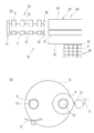
- the side view of the slitter which concerns on 1st Embodiment of this invention.
- the front view of the slitter shown in FIG. The plan view of the slitter shown in FIG.
- the external perspective view of the winding core which concerns on one Embodiment of this invention.
- the external perspective view of the winding product which concerns on one Embodiment of this invention.
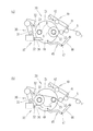
- (a) is a side view showing a state at the end of winding
- (b) is a side view showing a state in which a turret is swiveled.
- (c) is a side view showing a state when the web is cross-cut
- (d) is a side view showing a state after the web is cut.
- (e) is a side view showing a state at the start of winding the web to a new winding core
- (f) is a view during winding of the web on the second winding shaft.
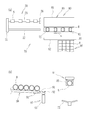
- (a) is a plan view showing the arrangement of a working device when receiving a winding core from a stocker, and (b) is a winding in which a winding product transfer shaft is transferred by a transfer plate.
- (c) is a plan view showing the arrangement of a working device when the winding core received by the winding core preparation shaft is passed to the winding device, and (d) is the first diagram. The plan view which shows the state which sent out the winding core to the 1st winding shaft side.
- (e) is a plan view showing the arrangement of a working device when the wound product is carried out by the product taking-out device, and (f) is a drawing product from the winding product transfer shaft.
- the side view of the slitter which concerns on the 2nd Embodiment of this invention.
- the front view of the slitter which concerns on the 2nd Embodiment of this invention.
- the plan view of the slitter which concerns on the 2nd Embodiment of this invention.
- (a) is a side view showing a completed winding product on the first winding shaft, and (b) is a winding of the web on the second winding shaft.
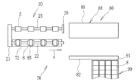
- (a) is a plan view of a slitter showing a state before the winding core is supplied to the working apparatus, and (b) is a side view showing a main part of the slitter in the same state. ..
- (a) is a plan view of a slitter showing a state in which the first four winding cores of the stocker are placed on a winding core cradle, and (b) is a plan view of the same state.
- Side view showing the main part of the slitter is a plan view of a slitter showing a state before the winding core is supplied to the working apparatus.
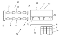
- (a) is a plan view of a slitter showing a state in which the winding cores on the winding core cradle are aligned at predetermined intervals by an alignment device, and (b) is a slitter in the same state.
- (a) is a plan view of a slitter showing a state immediately before mounting the winding core on the first winding shaft, and (b) shows a main part of the slitter in the same state.
- Side view The plan view of the slitter which showed the state which the winding core was attached to the 1st winding shaft in the 2nd Embodiment of this invention.
- FIG. 1 The plan view of the slitter which showed the state which the arm and the saucer were retracted in the 2nd Embodiment of this invention.
- (a) is a plan view of a slitter showing a state in which winding to a winding core mounted on a second winding shaft is completed, and (b) is a winding in the same state.
- (a) is a plan view of a slitter showing a completed winding product
- (b) is a side view showing a main part of a winding device in the same state. ..
- the plan view of the slitter showing the state immediately before passing the wound product to the product unloading table of the product unloading device.
- the plan view of the slitter showing the state in which the wound product is delivered to the product take-out table.
- the side view which shows the main part of the working apparatus which concerns on 2nd Embodiment of this invention.
- FIG. 1 is a side view of the slitter 1 according to the first embodiment
- FIG. 2 is a front view
- FIG. 3 is a plan view.
- FIG. 4 shows an external perspective view of the winding core 8
- FIG. 5 shows an external perspective view of the wound product 10.
- the main part of the slitter 1 is housed in the case 2.
- the wide web 4 unwound from the wide web roll 3 is slit to form a narrow web 5, which is wound around a winding core 8 mounted on the winding device 20 to wind up the product 10 (see FIG. 5). ).
- the winding core 8 is a cylindrical body, and a double-sided adhesive tape 11 for fixing the narrow web 5 at the start of winding is attached before the winding core 8 is attached to the winding device 20.
- the winding product 10 is a winding product 10 in which a narrow web 5 is wound around a winding core 8, and an adhesive tape 12 is attached to a terminal to be a final product.
- the slitter 1 includes a device for passing the winding core 8 to the winding device 20 and a device for carrying out the winding product 10, and the winding product 10 is made from the wide web roll 3 to make the winding product 10. It is a device that can automatically perform a series of steps up to carrying out the 10.
- the wide web 4 unwound from the wide web roll 3 reaches the position of the slit blade 7 via a plurality of guide rollers such as the guide roller 6.
- the wide web 4 is slit into a plurality of narrow webs 5 by the slit blade 7.
- the narrow web 5 is guided by the roller 13 or the roller 14 and is supplied to either the winding device 20 arranged in the upper and lower two stages.
- the take-up device 20 is a turret type provided with a pair of take-up shafts.
- the take-up shafts are designated by different reference numerals, one take-up shaft is referred to as a first take-up shaft 22, and the other take-up shaft is referred to as a second take-up shaft 23.
- the first take-up shaft 22 and the second take-up shaft 23 are provided on the turret 21.
- the winding core 8 is mounted on the first winding shaft 22 in advance, and the winding core 8 rotates integrally with the first winding shaft 22, so that the narrow web 5 is wound around the winding core 8. go.
- the winding core 8 is gripped by the first winding shaft 22 by a chuck mechanism (not shown) built in the first winding shaft 22. Further, during winding, as shown in FIG. 2, the tip of the first winding shaft 22 is supported by the support plate 26, and the first winding shaft 22 is in a double-sided state.
- the support plate 26 is a movable body, and the support plate 26 can be retracted to put the first take-up shaft 22 in a cantilever state. Assuming that the wide web roll 4 is slit into the four narrow webs 5 by the slit blade 7, the four narrow webs are alternately wound by the upper and lower winding devices 20.
- the wide web roll 4 is slit into four narrow webs 5a to 5d, and the webs 5a and 5c are wound by the upper winding device 20 and the web 5b, 5d is wound by the lower winding device 20.
- the narrow web 5 is cut by the cross-cut mechanism 40, and the terminal of the web 5 is labeled with the label 12 by the terminal processing mechanism 30 (see FIG. 5). Is affixed to complete the winding product 10.
- the completed take-up product 10 is transported to the next process by the transport mechanism 35.
- the transport mechanism 35 includes a transport plate 36, and the tip end portion of the transport plate 36 can be moved to the end face of the winding product 10 by the rotational movement of the transport plate 36 (see FIG. 8 (e)).
- the winding product 10 is shown on the first winding shaft 22 of the lower winding device 20 for convenience.
- This state corresponds to the state of FIG. 8 (e) described later.
- the tip of the transport plate 36 is on the end face of the take-up product 10, and the transport plate 36 moves along the guide shaft 25 to transport the take-up product 10 to the product take-out device 65 side. ..
- the support plate 26 corresponding to the first take-up shaft 22 can be retracted so that the first take-up shaft 22 can be in a cantilever state.
- the first take-up shaft 22 may be bent and deformed by the load of the take-up product 10, but the first take-up shaft 22 may be deformed before the support plate 26 is retracted.
- the load of the take-up product 10 can be dispersed and the deformation of the first take-up shaft 22 can be suppressed.
- FIGS. 6 to 8 shows a side view of the vicinity of the winding device 20 in each process.
- FIG. 6A shows the state at the end of winding. In this state, the winding of the web 5 to the winding core 8 mounted on the first winding shaft 22 has reached full winding, and the touch roll 15 holding the web 5 at the time of winding is retracted.
- FIG. 6B shows a state in which the turret 21 is turned. By turning the turret 21, the positions of the first take-up shaft 22 and the second take-up shaft 23 in FIG. 6A are exchanged.
- FIG. 7 (c) shows the state of the web 5 at the time of cross-cutting.
- the retracted touch roll 15 returns, and the cross-cut pedestal 48 rises to a position supporting the web 5 due to the inclination of the cylinder 46 of the web receiving mechanism 45 and the extension of the rod 47.
- the cross-cut mechanism 40 rotates about the shaft 41, the share blade 42 descends to a position facing the cross-cut pedestal 48, and is in contact with the web 5.
- the web 5 is cut by reciprocating the Char blade 42.
- FIG. 7 (d) shows the state of the web 5 after cutting.
- the winding of the web 5 to the winding core 8 mounted on the first winding shaft 22 is completed.
- the terminal processing mechanism 30 rotates about the shaft 31, and the label sticking roller 32 is in contact with the web 5 wound around the winding core 8.
- the terminal processing mechanism 30 operates, and the label (adhesive tape) is pressed against the terminal of the web 5.
- the label 12 (see FIG. 5) is affixed to the terminal of the web 5, and the winding product 10 is completed.
- the timing of attaching the label 12 is calculated by calculation based on the cut position of the web 5 and the web speed.
- FIG. 8 (e) shows the state at the start of winding the web 5 to the new winding core 8.
- the web 5 is wound around the winding core 8 mounted on the second winding shaft 23, and the winding product 10 is carried out from the winding device 20.
- This carry-out is carried out by the transport plate 36.
- the tip of the transport plate 36 is moved to the side surface of the wound product 10 by the rotation of the transport plate 36 around the shaft 37.
- the take-up product 10 is pushed by the transport plate 36 and moves in the axial direction of the first take-up shaft 22 to move the take-up product. 10 is carried out from the winding device 20.
- the chuck mechanism is released from gripping the winding core 8 on the first winding shaft 22, and as described above, the support plate 26 shown in FIG. 2 is connected to the winding product transfer shaft 57. ,evacuate.
- the take-up product 10 carried out from the take-up device 20 is received by the take-up product transfer shaft 57, as will be described in detail later with reference to FIG.
- FIG. 8 (f) shows the winding state of the web 5 on the second winding shaft 23.
- the web 5 is wound around the second take-up shaft 23, and a new winding core 8 is attached to the first take-up shaft 22.
- the transport plate 36 carrying out the take-up product 10 returns to the turret 21 side, the transport plate 36 causes the new core to be received by the core preparation shaft 56. 8 is conveyed to the turret 21 side along the first winding shaft 22, and a new winding core 8 is passed to the first winding shaft 22.
- the winding product 10 mounted on the first winding shaft 22 is transferred to the winding product transfer shaft 57 (
- the winding core 8 received by the winding core preparing shaft 56 (winding core preparing means) is passed to the first winding shaft 22 as well as being received by the winding product transfer means).
- a winding device not provided with the second winding shaft 23 may be used, but in that case, until the winding product 10 is carried out and the winding core 8 is attached. Since the winding work is interrupted and becomes inefficient, a so-called turret type winding provided with a pair of the first winding shaft 22 and the second winding shaft 23 like the winding device 20 of the present embodiment. It is preferable to adopt a taking device.
- the winding core 8 is placed on the stocker 50, which is the supply source thereof. As shown in FIG. 2, the winding core 8 is placed on the inclined surface of the stocker 50, and in FIG. 3, the winding core 8 is aligned with the lower end 51 of the inclined surface at the head.
- a working device 55 is arranged adjacent to the stocker 50. Although the details will be described later, the working device 55 is a device that receives the winding core 8 from the stocker 50, passes it to the winding device 20, and receives the winding product 10 from the winding device 20.
- the slitter 1 continuously supplies the winding core 8 to the winding device 20 and carries out the winding product 10 from the slitter 1 by switching the arrangement of the working device 55 shown in FIG. Can be done.
- the working device 55 includes a winding core preparation shaft 56 and a winding product transfer shaft 57, both of which are arranged orthogonally in an L shape.
- the winding core preparation shaft 56 is a winding core preparing means for receiving the winding core 8 from the stocker 50.
- the take-up product transfer shaft 57 is a take-up product transfer means for transferring the take-up product 10 received from the take-up device 20 to the product take-out device 65 side.
- the working device 55 can be swiveled around the swivel shaft 58, and can be moved in the X-axis direction (width direction of the slitter 1) and the Y-axis direction (depth direction of the slitter 1) in the plane direction.
- the winding core preparation shaft 56 as the winding core preparation means and the winding product transfer shaft 57 as the winding product transfer means are examples, and may be any as long as the winding core 8 and the winding product 10 can be delivered. If it is a shaft as in this embodiment, the winding core 8 and the winding product 10 can be delivered with a simple structure.
- FIG. 9 is a flowchart showing a series of processes by the working device 55.
- 10 to 12 are enlarged views of the vicinity of the working device 55 in FIG. 3, and are views showing the arrangement of the working devices 55 in the order of processes.
- FIG. 10A shows the arrangement of the working device 55 when the winding core 8 is received from the stocker 50.
- the tip of the winding core preparation shaft 56 faces the winding core 8 on the stocker 50.
- the winding core 8 is extruded toward the winding core preparation shaft 56 by an extrusion means such as an air cylinder (not shown).
- the winding core preparation shaft 56 is inserted through the hollow portion of the winding core 8 (see FIG. 10B), and the winding core preparation shaft 56 receives the winding core 8 (FIG. 9). Step 100).
- FIG. 10B shows the arrangement of the working device 55 when the take-up product transfer shaft 57 receives the take-up product 10 conveyed by the transfer plate 36.
- the working device 55 is advancing toward the first take-up shaft 22 from the state of FIG. 10 (a) (arrow a in FIG. 10 (a)), and is in the first take-up shaft 22.
- the take-up product transfer shaft 57 is connected.
- the take-up product transfer shaft 57 can receive the take-up product 10 conveyed along the first take-up shaft 22 by the transfer plate 36 (step 101 in FIG. 9).
- FIG. 11C shows the arrangement of the working device 55 when the winding core 8 received by the winding core preparation shaft 56 is passed to the first winding shaft 22.
- the working device 55 temporarily retracts from the state of FIG. 10 (b) (arrow b in FIG. 10 (b)), and the core preparation shaft 56 turns around the swivel shaft 58 in the direction toward the first take-up shaft 22. After that (arrow c in FIG. 10 (b)), it is moving forward (arrow d in FIG. 11 (c)).
- the winding core preparation shaft 56 is connected to the first winding shaft 22.
- the take-up product 10 received by the take-up product transfer shaft 57 is transferred to the product take-out device 65 side by the above-mentioned turning.
- the transport plate 36 is in the retracted state (see FIG. 1) from the state of FIG. 10 (b), and in the state of FIG. 11 (c), the first winding core is in the retracted state along the guide shaft 25. It has moved to the position of the end face of 8.
- the tip of the transport plate 36 becomes a winding core.
- the winding core 8 can be sent out to the first winding shaft 22 side in a state of being in contact with the end surface of 8, and the winding core 8 can be passed to the winding device 20 (step 102 in FIG. 9).
- FIG. 11D shows a state in which the first winding core 8 is sent out to the first winding shaft 22.
- the winding core 8 passes below the adhesive material attaching device 60 shown in FIG.
- the adhesive material attaching device 60 attaches the double-sided tape 11 to the winding core 8 according to the passing speed of the winding core 8 (see FIG. 4).
- the double-sided tape 11 is also attached to the second winding core 8 and sent out to the first winding shaft 22.
- FIG. 12 (e) shows a state when the take-up product 10 is carried out by the product take-out device 65.
- the product unloading device 65 includes a transport plate 66.
- the transport mechanism including the transport plate 66 is the same mechanism as the transport mechanism 35 (see FIG. 1) including the transport plate 36. In 2, the transport plate 66 is in the retracted state, and when it rises due to the rotational movement, the tip moves to the position of the end face of the winding product 10 as shown in FIG. 12 (e).
- the take-up product 10 is taken out from the take-up product transfer shaft 57 by sliding the transfer plate 66 in the direction of pushing out the take-up product 10 from the take-up product transfer shaft 57 (arrow f). It will be carried out (step 103 in FIG. 9).
- the unwound products 10 that have been carried out are arranged at an arbitrary place (such as a trolley).
- FIG. 12 (f) shows a state in which the take-up product 10 is taken out from the take-up product transfer shaft 57.
- the winding core preparation shaft 56 is swiveled in the direction toward the stocker 50 (arrow g), whereby the arrangement of the winding core 55 is shown in FIG. 10 (a).
- FIG. 10 (a) shows the arrangement of the winding core 55 in FIG. 10 (a).
- new take-up products 10 are sequentially carried out from the slitter 1.
- the winding core 8 can be continuously supplied to the winding device 20 and the winding product 10 can be continuously carried out. can. Further, as described above, the winding to the winding core 8 in the winding device 20 and the subsequent winding to the new winding core 8 can be continuously performed. Therefore, in the present embodiment, it is possible to automate a series of processes such as supplying the winding core 8 to the winding device 20, winding the winding core 8 to the winding core 8, and carrying out the winding product 10. ..
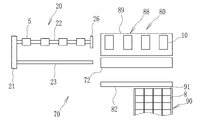
- FIG. 13 is a side view of the slitter 70 according to the second embodiment
- FIG. 14 is a front view
- FIG. 15 is a plan view.
- Each figure is a schematic diagram showing a basic configuration, and details of the mechanism are not shown as appropriate.
- the side view of FIG. 13 shows the Y-axis direction of the slitter 70 (the depth direction of the slitter 70), and is a view of the slitter 70 of FIG. 15 as viewed from the B direction.
- FIG. 14 shows the X-axis direction of the slitter 70 (the width direction of the slitter 70), and is a view of the slitter 70 of FIG. 15 as viewed from the C direction.
- the plan view of FIG. 15 shows the X-axis direction and the Y-axis direction of the slitter 70, and is a view of the slitter 70 of FIG. 13 as viewed from the A direction.
- the slitter 70 is arranged adjacent to the stocker 90.
- the stocker 90 is a supplier of the winding core 8, and the winding core 8 is placed on an inclined surface of the stocker 90.
- the winding cores 8 are arranged in four rows starting from the lower end 91 of the inclined surface of the stocker 90.
- the winding core 8 and its description shown in FIG. 4, the winding product 10 shown in FIG. 5 and the description thereof are the same as those in the first embodiment.
- the slitter 70 includes a winding device 20 and a working device 80.
- the configuration of the winding device 20 shown in FIG. 13 is the same as that of the winding device 20 shown in FIG. Further, for convenience of illustration, the terminal processing mechanism 30 of FIG. 1 is not shown in FIG.
- the outline of the process from the wide web roll 3 to the completion of the take-up product 10 described with reference to FIG. 1 is the same as in the second embodiment, and the same process will be described. Is omitted.
- the working device 80 is arranged adjacent to the stocker 90.
- the working device 80 is a device that receives the winding core 8 from the stocker 90, passes it to the winding device 20, and receives the winding product 10 from the winding device 20.
- the working device 80 includes a winding product transfer mechanism 71 which is a winding product transfer means, a winding core delivery mechanism 81, and a winding core preparing mechanism 84 which is a winding core preparing means.
- the take-up product transfer mechanism 71 is a mechanism for transferring the take-up product 10 received from the take-up device 20 to the product take-out device 88 (see FIGS. 15 and 27), but the take-up product 10 is moved to the work device 80 side. It also serves as a transport mechanism for transporting to.
- the take-up product transfer mechanism 71 includes a saucer 72, a saucer tilting mechanism 73, a saucer support 74, and a saucer elevating mechanism 75. Details of the operation of the take-up product transfer mechanism 71 will be described later.
- the winding core delivery mechanism 81 includes a winding core pedestal 82 and a pedestal elevating mechanism 83, and the winding core 8 received by the winding core pedestal 82 is passed to the winding core preparation mechanism 84.
- the winding core preparation mechanism 84 includes an arm 85 which is a winding core gripping means, and the arm 85 grips the winding core 8 received from the winding core cradle 82.
- the mechanisms of the saucer tilting mechanism 73, the saucer elevating mechanism 75, and the pedestal elevating mechanism 83 are not particularly limited, and in the present embodiment, the rod expands and contracts from the cylinder.
- the take-up product transfer mechanism 71 and the winding core preparation mechanism 84 included in the working device 80 are integrated with a frame body 86 composed of a pair of vertical frames 78 and a pair of horizontal frames 79.
- the frame 86 can move horizontally along the upper rail 76 and the lower rail 77 (arrows h and i), and the winding product transfer mechanism 71 and the winding core preparation mechanism 84 also move horizontally along with this horizontal movement. ..
- the winding device 20 described with reference to FIGS. 6 and 7 is used.
- the process from the end to the completion of the take-up product 10 is the same in the second embodiment.
- the first embodiment as shown in FIG. 3, the example in which the wide web roll 4 is slit into the four narrow webs 5a to 5d has been described, but in the second embodiment, the figure is shown.
- the example in which the wide web roll 4 is slit into eight narrow webs 5a to 5h will be described, but it may be slit into two or more.
- the webs 5a, 5c, 5e, and 5g are wound by the upper winding device 20
- the webs 5b, 5d, 5f, and 5h are wound by the lower winding device 20.
- the winding product transfer mechanism 71 shown in FIG. 13 also serves as the mechanism corresponding to the transfer mechanism 35 in FIG. 1.
- the outline of the operation of the take-up product transfer mechanism 71 will be described with reference to FIG.
- FIG. 16A shows the state at the start of winding the web 5 to the new winding core 8 mounted on the second winding shaft 23 after the winding product 10 is completed on the first winding shaft 22. Shows. In this state, the web 5 is wound around the winding core 8 mounted on the second winding shaft 23, and the winding product 10 is carried out from the winding device 20. This unloading is performed in a state where the take-up product 10 is placed on the saucer 72 constituting the take-up product transfer mechanism 71 shown in FIG. In the state of FIG. 16A, the saucer 72 is raised integrally with the saucer support 74 (see FIG. 13) by the saucer elevating mechanism 75 (see FIG. 13) (arrow j).
- the take-up product 10 moves in the axial direction of the first take-up shaft 22, and the take-up product 10 is moved from the take-up device 20. It is carried out.
- the saucer 72 moves by the horizontal movement of the take-up product transfer mechanism 71 integrated with the horizontal movement of the frame body 86.
- the chuck mechanism is released from gripping the winding core 8 on the first take-up shaft 22.
- the support plate 26 corresponding to the first take-up shaft 22 is retracted, and the first take-up shaft 22 is in a cantilever state.
- FIG. 16B shows the winding state of the web 5 on the second winding shaft 23. In this state, the web 5 is wound around the second take-up shaft 23, and a new winding core 8 is attached to the first take-up shaft 22. The mounting of the new winding core 8 will be described later.
- the winding product 10 mounted on the first winding shaft 22 is wound while the web 5 is being wound on the second winding shaft 23.
- the winding core 8 received by the winding product transfer mechanism 71 (winding product transfer means) and the winding core preparation mechanism 84 (winding core preparation means) are passed to the first winding shaft 22.
- FIG. 17 shows a state before the winding core 8 is supplied to the working device 80.
- (a) is a plan view showing a main part of the slitter 70
- (b) is a side view showing the main part of the slitter 70 (the same applies to FIGS. 18 to 20).
- the arm 85 is not shown as appropriate for convenience of illustration.
- the winding of the web 5 to the winding core 8 mounted on the second winding shaft 23 has started.
- the winding core 8 is placed on the stocker 90.
- the winding core 8 is the lower end 91 of the inclined surface of the stocker 90, and its movement is restricted by the stopper 92.
- the winding cores 8 are arranged in four rows, and the four winding cores 8 are sequentially conveyed to the first winding shaft 22 from the beginning.
- the number of rows of the winding cores 8 in the stocker 90 does not have to correspond to the number of mounted cores, and may be short rows.
- FIG. 18A shows a plan view of the slitter 70 in a state where the four winding cores 8 at the head of the stocker 90 are placed on the winding core cradle 82.
- the regulation is released by tilting the stopper 92 from the state shown in FIG. 17 (b) (arrow k), and the winding core 8 is placed on the winding core pedestal 82 as shown in FIG. 18 (b). ..
- the winding core 8 on the stocker 90 is restricted from moving again by the stopper 92.
- FIG. 19A shows a plan view of the slitter 70 in a state where the winding cores 8 on the winding core cradle 82 are aligned at predetermined intervals by the aligning device.
- the aligning device is the same mechanism as the transport mechanism 35 (see FIG. 1) including the transport plate 36.
- the winding core pedestal 82 is raised by the pedestal elevating mechanism 83, and the winding core 8 is raised to the position of the arm 85.
- the arm 85 is slid from this state (arrow m)
- the winding core 8 is gripped by the arm 85.
- the winding core pedestal 82 is lowered to its original position by the pedestal elevating mechanism 83.
- the arm 85 gripping the winding core 8 moves toward the saucer 72 (arrow l).
- FIG. 20 shows a plan view of the slitter 70 in a state immediately before the winding core 8 is mounted on the first winding shaft 22.
- the arm 85 grips the winding core 8
- the winding core 8 gripped by the arm 85 is a saucer 72.
- the central axis of the first winding shaft 22 and the central axis of the winding core 8 coincide with each other.
- the arm 85 gripping the winding core 8 moves toward the first winding shaft 22 (arrow n). This movement is due to the movement of the frame body 86 shown in FIG. 14, and the saucer 72 also moves together with the movement of the arm 85.
- the double-sided tape 11 is attached to the winding core 8 by the adhesive material attaching device 60 (not shown in FIG. 20) as in the first embodiment (see FIG. 4).
- the method of attaching the adhesive is arbitrary. For example, if each guide roller 6 or the like (see FIG. 1) is non-adhesive (released), the adhesive is applied to the wide web 4 in front of the slit. Can be done. In this case, it is not necessary to directly attach the double-sided tape 11 or the like to the core 8.
- FIG. 21 shows a plan view of the slitter 70 in a state where the winding core 8 is mounted on the first winding shaft 22. From this state, the arm 85 releases the grip of the winding core 8, and the arm 85 retracts to the original position together with the saucer 72 (arrow o).
- FIG. 22 shows a plan view of the slitter 70 in a state where the arm 85 and the saucer 72 are retracted. In this state, the holding of the winding core 8 on the first winding shaft 22 is completed, and the first winding shaft 22 is supported by the support plate 26 and is in a double-sided state. By rotating the second winding shaft 23 to which the winding core 8 is mounted in advance until the winding core 8 is mounted on the first winding shaft 22, the winding mounted on the second winding shaft 23 The web 5 to the core 8 is being wound up.
- FIG. 23A shows a plan view of the slitter 70 in a state where the winding of the web 5 to the winding core 8 mounted on the second winding shaft 23 is completed.
- the main part of the side surface of the winding device 20 at this time is shown in FIG. 23 (b).
- FIG. 23B shows the winding of the web 5 to the winding core 8 mounted on the second winding shaft 23 has reached full winding.
- FIG. 24 shows a plan view of the slitter 70 in a state where the turret 21 is swiveled from the state of FIG. 23 and the winding product 10 is completed. The steps during this period are as described with reference to FIGS. 6 and 7.
- the saucer 72 has moved to the position of the second take-up shaft 23.
- the saucer 72 below the take-up shaft 23 is raised (arrow r), the saucer 72 receives the take-up product 10, and the weight of the take-up product is not applied to the second take-up shaft 23. To do so.
- FIG. 24 shows a plan view of the slitter 70 in a state where the turret 21 is swiveled from the state of FIG. 23 and the winding product 10 is completed. The steps during this period are as described with reference to FIGS. 6 and 7.
- the saucer 72 has moved to the position of the second take-up shaft 23.
- the saucer 72 below the take-up shaft 23 is raised (arrow r)
- the support plate 26 that supported the second take-up shaft 23 is retracted (arrow p), and the second take-up shaft 23 is placed in a cantilever state. Subsequently, the saucer 72 receiving the take-up product 10 is transferred to the product take-out device 88 side (arrow q).
- FIG. 25 shows a plan view of the slitter 70 in a state immediately before the take-up product 10 is handed over to the product take-out table 89 of the product take-out device 88.
- the take-up product 10 on the saucer 72 is delivered to the product take-out table 89.
- the winding of the web 5 to the winding core 8 mounted on the first winding shaft 22 has started.
- FIG. 26 shows a state in which the take-up product 10 is delivered to the product take-out table 89.
- the slitter 70 returns to the state of FIG. 17 (a). After that, by repeating each step described with reference to FIGS. 17 to 26, a new take-up product 10 is sequentially carried out from the slitter 70.
- FIG. 27 is a side view showing a main part of the working device 80.
- the illustration of FIG. 26 is limited to the mechanism for carrying out the take-up product 10, and the illustration of other mechanisms is omitted.
- the product receiving trolley 95 is an example, as long as it can receive the product, it may have another structure.
- the take-up product 10 is delivered onto the product take-out table 89 included in the product take-out device 88. Further, by tilting the product take-out stand 89 by a tilting mechanism (not shown) such as a cylinder mechanism (arrow u), the take-up product 10 is carried out onto the product receiving stand 96 included in the product receiving carriage 95.
- the upper and lower product take-out stands 89 of the product take-out device 88 can be raised and lowered by a lift mechanism (not shown), and the take-up product 10 on the lower product take-out stand 89 is also carried out onto the product receiving stand 96. Can be done.
- the winding core 8 is supplied to the winding device 20 by switching the arrangement of the working device 80 as in the first embodiment. And, the take-up product 10 can be continuously carried out. Further, as described above, the winding to the winding core 8 in the winding device 20 and the subsequent winding to the new winding core 8 can be continuously performed. Therefore, in the present embodiment, it is possible to automate a series of processes such as supplying the winding core 8 to the winding device 20, winding the winding core 8 to the winding core 8, and carrying out the winding product 10. ..
- the manual work of the worker can be omitted in the series of steps of the slitter 70, so that the manual work of the worker can be omitted.
- the decrease in the operating rate and the work load of the workers will be eliminated.
- the stockers 50 and 90 which are the supply sources of the winding core 8 are not limited to the structures exemplified in each embodiment as long as they have a structure for supplying the winding core 8 to the winding core preparing means 56 and 84.
- the product take-out devices 65 and 88 are not limited to the structures exemplified in each embodiment as long as the take-up product 10 can be taken out from the take-up product transfer means 57 and 71.
- the terminal processing mechanism 30, the transport mechanism 35, the cross-cut mechanism 40, and the adhesive material attaching device 60 shown in FIG. 2 have other configurations as long as they can realize the same functions. You may.
- Winding device 1st winding shaft 23 2nd winding shaft 30 Terminal processing mechanism 35 Transport mechanism 36 Transport plate 50,90 Stocker (source of winding core) 55,80 Work equipment 56 Wind core preparation shaft (core preparation means) 57 Take-up product transfer shaft (wind-up product transfer means) 58 Swing shaft 60 Adhesive sticking device 65,88 Product take-out device 71 Take-up product transfer mechanism (wind-up product transfer means) 72 Reservoir 82 Winding core cradle 84 Winding core preparation mechanism (winding core preparation means) 89 Product take-out stand
Landscapes
- Replacement Of Web Rolls (AREA)
- Winding Of Webs (AREA)
Priority Applications (5)
| Application Number | Priority Date | Filing Date | Title |
|---|---|---|---|
| JP2021544247A JP7467484B2 (ja) | 2020-06-10 | 2021-05-12 | スリッタ |
| KR1020227033233A KR20230020940A (ko) | 2020-06-10 | 2021-05-12 | 슬리터 |
| CN202180030348.3A CN115485222A (zh) | 2020-06-10 | 2021-05-12 | 分切机 |
| TW110120222A TWI888569B (zh) | 2020-06-10 | 2021-06-03 | 切割機 |
| JP2023162966A JP7576140B2 (ja) | 2020-06-10 | 2023-09-26 | スリッタ |
Applications Claiming Priority (2)
| Application Number | Priority Date | Filing Date | Title |
|---|---|---|---|
| JP2020101036 | 2020-06-10 | ||
| JP2020-101036 | 2020-06-10 |
Publications (1)
| Publication Number | Publication Date |
|---|---|
| WO2021251051A1 true WO2021251051A1 (ja) | 2021-12-16 |
Family
ID=78845963
Family Applications (1)
| Application Number | Title | Priority Date | Filing Date |
|---|---|---|---|
| PCT/JP2021/018128 Ceased WO2021251051A1 (ja) | 2020-06-10 | 2021-05-12 | スリッタ |
Country Status (5)
| Country | Link |
|---|---|
| JP (2) | JP7467484B2 (https=) |
| KR (1) | KR20230020940A (https=) |
| CN (1) | CN115485222A (https=) |
| TW (1) | TWI888569B (https=) |
| WO (1) | WO2021251051A1 (https=) |
Cited By (1)
| Publication number | Priority date | Publication date | Assignee | Title |
|---|---|---|---|---|
| JP2025010524A (ja) * | 2023-07-07 | 2025-01-21 | フォルクスヴァーゲン アクチエンゲゼルシャフト | コイルまたは巻心を交換するための装置、コイルまたは巻心を交換するためのアセンブリおよび方法 |
Citations (6)
| Publication number | Priority date | Publication date | Assignee | Title |
|---|---|---|---|---|
| JPS63272738A (ja) * | 1987-04-28 | 1988-11-10 | Hamada Insatsuki Seizosho:Kk | 自動タブ貼着装置 |
| JPH0577984A (ja) * | 1991-09-18 | 1993-03-30 | Kawanoe Zoki Kk | 巻取コアの糊付装置 |
| JPH08188306A (ja) * | 1995-01-10 | 1996-07-23 | Dainippon Printing Co Ltd | シート巻取体製造装置およびコア供給装置 |
| JP2558535B2 (ja) * | 1990-03-19 | 1996-11-27 | 株式会社片岡機械製作所 | 巻取ロール取り出し兼巻芯装着装置 |
| JPH08324845A (ja) * | 1995-05-30 | 1996-12-10 | Placo Co Ltd | 紙管自動供給機構を備えたフィルム巻取装置 |
| JPH10120261A (ja) * | 1996-10-24 | 1998-05-12 | Mitsubishi Heavy Ind Ltd | ウエブ巻取りロールの巻端処理装置及び処理方法 |
Family Cites Families (14)
| Publication number | Priority date | Publication date | Assignee | Title |
|---|---|---|---|---|
| JPS5935809B2 (ja) * | 1977-07-27 | 1984-08-30 | 石川島播磨重工業株式会社 | 自動貼付装置付ワインダ装置 |
| JPH04129962A (ja) * | 1990-09-18 | 1992-04-30 | Fuji Tekkosho:Kk | 巻取機における巻芯管への粘着テープ貼り付け方法及びその装置 |
| FI112349B (fi) * | 2000-04-12 | 2003-11-28 | Metso Paper Inc | Menetelmä ja sovitelma pehmopaperirullien siirtämiseksi tampuuriraudalta |
| JP4452414B2 (ja) | 2001-02-14 | 2010-04-21 | 萩原工業株式会社 | スリッタ巻取製品搬出装置 |
| JP2003165657A (ja) | 2001-11-30 | 2003-06-10 | Mitsubishi Heavy Ind Ltd | ワインダ及びワインダ用コア持ち込み装置 |
| JP5410223B2 (ja) * | 2009-09-29 | 2014-02-05 | 富士フイルム株式会社 | ウェブの巻取り方法、及び機能性フィルムの製造方法 |
| DE102013108829B4 (de) * | 2013-05-13 | 2019-03-28 | Windmöller & Hölscher Kg | Rollenhandlingsystem für einen Wickler sowie Verfahren hierzu |
| JP5986556B2 (ja) * | 2013-12-13 | 2016-09-06 | 株式会社不二鉄工所 | シート巻取装置 |
| CN104773563B (zh) * | 2015-03-19 | 2018-07-13 | 上海兰庆新材料技术股份有限公司 | 一种能实现卷芯上定点切割的收卷装置 |
| CN104773565B (zh) * | 2015-03-30 | 2016-08-24 | 东莞市鑫晖达机械制造有限公司 | 一种纸芯筒自动上料装置 |
| CN107032104B (zh) * | 2016-02-04 | 2023-07-04 | 潮州市彩达包装机械有限公司 | 纵向分切机数控自动卸料装置 |
| CN108132262A (zh) * | 2016-11-30 | 2018-06-08 | 住友化学株式会社 | 缺陷检查装置、缺陷检查方法及隔膜卷绕体的制造方法 |
| JP6976119B2 (ja) * | 2017-09-27 | 2021-12-08 | 株式会社日本製鋼所 | 巻取機 |
| CN108190585B (zh) * | 2017-12-29 | 2020-03-10 | 常德金德新材料科技股份有限公司 | 一种复合机收卷自动剥接装置 |
-
2021
- 2021-05-12 CN CN202180030348.3A patent/CN115485222A/zh active Pending
- 2021-05-12 WO PCT/JP2021/018128 patent/WO2021251051A1/ja not_active Ceased
- 2021-05-12 JP JP2021544247A patent/JP7467484B2/ja active Active
- 2021-05-12 KR KR1020227033233A patent/KR20230020940A/ko active Pending
- 2021-06-03 TW TW110120222A patent/TWI888569B/zh active
-
2023
- 2023-09-26 JP JP2023162966A patent/JP7576140B2/ja active Active
Patent Citations (6)
| Publication number | Priority date | Publication date | Assignee | Title |
|---|---|---|---|---|
| JPS63272738A (ja) * | 1987-04-28 | 1988-11-10 | Hamada Insatsuki Seizosho:Kk | 自動タブ貼着装置 |
| JP2558535B2 (ja) * | 1990-03-19 | 1996-11-27 | 株式会社片岡機械製作所 | 巻取ロール取り出し兼巻芯装着装置 |
| JPH0577984A (ja) * | 1991-09-18 | 1993-03-30 | Kawanoe Zoki Kk | 巻取コアの糊付装置 |
| JPH08188306A (ja) * | 1995-01-10 | 1996-07-23 | Dainippon Printing Co Ltd | シート巻取体製造装置およびコア供給装置 |
| JPH08324845A (ja) * | 1995-05-30 | 1996-12-10 | Placo Co Ltd | 紙管自動供給機構を備えたフィルム巻取装置 |
| JPH10120261A (ja) * | 1996-10-24 | 1998-05-12 | Mitsubishi Heavy Ind Ltd | ウエブ巻取りロールの巻端処理装置及び処理方法 |
Cited By (2)
| Publication number | Priority date | Publication date | Assignee | Title |
|---|---|---|---|---|
| JP2025010524A (ja) * | 2023-07-07 | 2025-01-21 | フォルクスヴァーゲン アクチエンゲゼルシャフト | コイルまたは巻心を交換するための装置、コイルまたは巻心を交換するためのアセンブリおよび方法 |
| JP7774102B2 (ja) | 2023-07-07 | 2025-11-20 | パワーコ エス・エー | コイルまたは巻心を交換するための装置、コイルまたは巻心を交換するためのアセンブリおよび方法 |
Also Published As
| Publication number | Publication date |
|---|---|
| KR20230020940A (ko) | 2023-02-13 |
| JP2023165843A (ja) | 2023-11-17 |
| TW202214509A (zh) | 2022-04-16 |
| JPWO2021251051A1 (https=) | 2021-12-16 |
| JP7467484B2 (ja) | 2024-04-15 |
| CN115485222A (zh) | 2022-12-16 |
| TWI888569B (zh) | 2025-07-01 |
| JP7576140B2 (ja) | 2024-10-30 |
Similar Documents
| Publication | Publication Date | Title |
|---|---|---|
| US8016223B2 (en) | Process and apparatus for loading and unloading an unwinding machine | |
| JP6918085B2 (ja) | ウェブ状の材料を巻き取りかつ巻成体を交換するための装置および方法 | |
| EP1344735B1 (en) | Winder for film of plastic material | |
| JP3107807B2 (ja) | シート積み上げ装置 | |
| CN107585612A (zh) | 一种复合机自动换卷装置 | |
| WO2009125698A1 (ja) | ワインダー | |
| WO2021251051A1 (ja) | スリッタ | |
| JPS62166017A (ja) | 帯材加工機械に帯材を導入するための搬送装置 | |
| US11866278B2 (en) | Paper mill rewinder with continuous reel change device | |
| JP2003276915A (ja) | 巻取部自動切替装置 | |
| JP3453350B2 (ja) | 連続巻出装置及びウェブの連続巻出方法 | |
| JP3196631U (ja) | シート分割巻取装置 | |
| JP3662375B2 (ja) | 帯状材料の供給方法及びその装置 | |
| JP4020522B2 (ja) | スリッタ巻取製品の搬出方法 | |
| JP3012081B2 (ja) | リール搬送装置 | |
| JP7245555B1 (ja) | 巻取装置及び搬送物の巻替方法 | |
| CN219489094U (zh) | 一种摩擦式收卷机的料头掀压重卷机构 | |
| JP2004167781A (ja) | 円筒状樹脂フィルム材料の成形ドラムへの供給方法及びその供給装置 | |
| JP2001072286A (ja) | スリッター装置における自動巻き替え装置 | |
| JPH03115044A (ja) | 巻取紙自動仕立装置 | |
| JP4801533B2 (ja) | 原紙ロール交換装置の原紙端部自動処理装置及び原紙端部自動処理方法 | |
| JP2013173596A (ja) | シート分割巻取装置 | |
| JP3348441B2 (ja) | 広幅帯状シート用スリッターリワインダー | |
| JP2811104B2 (ja) | 断裁製品の回収システム | |
| JP2000296949A (ja) | 帯状部材の切替巻出し方法および装置 |
Legal Events
| Date | Code | Title | Description |
|---|---|---|---|
| ENP | Entry into the national phase |
Ref document number: 2021544247 Country of ref document: JP Kind code of ref document: A |
|
| 121 | Ep: the epo has been informed by wipo that ep was designated in this application |
Ref document number: 21820855 Country of ref document: EP Kind code of ref document: A1 |
|
| NENP | Non-entry into the national phase |
Ref country code: DE |
|
| 122 | Ep: pct application non-entry in european phase |
Ref document number: 21820855 Country of ref document: EP Kind code of ref document: A1 |