WO2021234834A1 - パレット供給装置 - Google Patents
パレット供給装置 Download PDFInfo
- Publication number
- WO2021234834A1 WO2021234834A1 PCT/JP2020/019874 JP2020019874W WO2021234834A1 WO 2021234834 A1 WO2021234834 A1 WO 2021234834A1 JP 2020019874 W JP2020019874 W JP 2020019874W WO 2021234834 A1 WO2021234834 A1 WO 2021234834A1
- Authority
- WO
- WIPO (PCT)
- Prior art keywords
- pallet
- control device
- gantry
- cover body
- holding
- Prior art date
- Legal status (The legal status is an assumption and is not a legal conclusion. Google has not performed a legal analysis and makes no representation as to the accuracy of the status listed.)
- Ceased
Links
Images


Classifications
-
- B—PERFORMING OPERATIONS; TRANSPORTING
- B23—MACHINE TOOLS; METAL-WORKING NOT OTHERWISE PROVIDED FOR
- B23Q—DETAILS, COMPONENTS, OR ACCESSORIES FOR MACHINE TOOLS, e.g. ARRANGEMENTS FOR COPYING OR CONTROLLING; MACHINE TOOLS IN GENERAL CHARACTERISED BY THE CONSTRUCTION OF PARTICULAR DETAILS OR COMPONENTS; COMBINATIONS OR ASSOCIATIONS OF METAL-WORKING MACHINES, NOT DIRECTED TO A PARTICULAR RESULT
- B23Q7/00—Arrangements for handling work specially combined with or arranged in, or specially adapted for use in connection with, machine tools, e.g. for conveying, loading, positioning, discharging, sorting
- B23Q7/14—Arrangements for handling work specially combined with or arranged in, or specially adapted for use in connection with, machine tools, e.g. for conveying, loading, positioning, discharging, sorting co-ordinated in production lines
- B23Q7/1426—Arrangements for handling work specially combined with or arranged in, or specially adapted for use in connection with, machine tools, e.g. for conveying, loading, positioning, discharging, sorting co-ordinated in production lines with work holders not rigidly fixed to the transport devices
- B23Q7/1431—Work holder changers
-
- B—PERFORMING OPERATIONS; TRANSPORTING
- B23—MACHINE TOOLS; METAL-WORKING NOT OTHERWISE PROVIDED FOR
- B23Q—DETAILS, COMPONENTS, OR ACCESSORIES FOR MACHINE TOOLS, e.g. ARRANGEMENTS FOR COPYING OR CONTROLLING; MACHINE TOOLS IN GENERAL CHARACTERISED BY THE CONSTRUCTION OF PARTICULAR DETAILS OR COMPONENTS; COMBINATIONS OR ASSOCIATIONS OF METAL-WORKING MACHINES, NOT DIRECTED TO A PARTICULAR RESULT
- B23Q1/00—Members which are comprised in the general build-up of a form of machine, particularly relatively large fixed members
- B23Q1/25—Movable or adjustable work or tool supports
- B23Q1/44—Movable or adjustable work or tool supports using particular mechanisms
- B23Q1/48—Movable or adjustable work or tool supports using particular mechanisms with sliding pairs and rotating pairs
- B23Q1/4852—Movable or adjustable work or tool supports using particular mechanisms with sliding pairs and rotating pairs a single sliding pair followed perpendicularly by a single rotating pair
- B23Q1/4866—Movable or adjustable work or tool supports using particular mechanisms with sliding pairs and rotating pairs a single sliding pair followed perpendicularly by a single rotating pair followed perpendicularly by a single sliding pair
-
- B—PERFORMING OPERATIONS; TRANSPORTING
- B23—MACHINE TOOLS; METAL-WORKING NOT OTHERWISE PROVIDED FOR
- B23Q—DETAILS, COMPONENTS, OR ACCESSORIES FOR MACHINE TOOLS, e.g. ARRANGEMENTS FOR COPYING OR CONTROLLING; MACHINE TOOLS IN GENERAL CHARACTERISED BY THE CONSTRUCTION OF PARTICULAR DETAILS OR COMPONENTS; COMBINATIONS OR ASSOCIATIONS OF METAL-WORKING MACHINES, NOT DIRECTED TO A PARTICULAR RESULT
- B23Q11/00—Accessories fitted to machine tools for keeping tools or parts of the machine in good working condition or for cooling work; Safety devices specially combined with or arranged in, or specially adapted for use in connection with, machine tools
- B23Q11/08—Protective coverings for parts of machine tools; Splash guards
-
- B—PERFORMING OPERATIONS; TRANSPORTING
- B23—MACHINE TOOLS; METAL-WORKING NOT OTHERWISE PROVIDED FOR
- B23Q—DETAILS, COMPONENTS, OR ACCESSORIES FOR MACHINE TOOLS, e.g. ARRANGEMENTS FOR COPYING OR CONTROLLING; MACHINE TOOLS IN GENERAL CHARACTERISED BY THE CONSTRUCTION OF PARTICULAR DETAILS OR COMPONENTS; COMBINATIONS OR ASSOCIATIONS OF METAL-WORKING MACHINES, NOT DIRECTED TO A PARTICULAR RESULT
- B23Q11/00—Accessories fitted to machine tools for keeping tools or parts of the machine in good working condition or for cooling work; Safety devices specially combined with or arranged in, or specially adapted for use in connection with, machine tools
- B23Q11/0042—Devices for removing chips
- B23Q11/0053—Devices for removing chips using the gravity force
-
- B—PERFORMING OPERATIONS; TRANSPORTING
- B65—CONVEYING; PACKING; STORING; HANDLING THIN OR FILAMENTARY MATERIAL
- B65G—TRANSPORT OR STORAGE DEVICES, e.g. CONVEYORS FOR LOADING OR TIPPING, SHOP CONVEYOR SYSTEMS OR PNEUMATIC TUBE CONVEYORS
- B65G2201/00—Indexing codes relating to handling devices, e.g. conveyors, characterised by the type of product or load being conveyed or handled
- B65G2201/02—Articles
- B65G2201/0267—Pallets
Definitions
- the present invention relates to a pallet feeding device including a pallet accommodating device accommodating a plurality of pallets and transporting the pallets accommodated in the pallet accommodating device to a predetermined place.
- this pallet transport device is a device for transferring and transporting pallets via a pallet stocker, a processing station, and a setup station, and is a pallet stocker for transferring and storing pallets.
- the pallet When positioned to the side, the pallet is transferred between the first pallet mounting table and the processing station or setup station, and when positioned to the second pallet mounting table side, the second pallet mounting table and the processing station.
- it is provided with one pallet transfer means configured to transfer the pallet to and from the setup station.
- the pallet transfer device is configured to move the carriage with the pallet transfer means fixed so that the positions of the first and second pallet mounting tables are exchanged with respect to the processing station or the setup station.
- the bogie is configured to move in the front-rear direction by a bogie driving means on a track extending so as to be via the pallet stocker, a processing station and a setup station, and the pallet transfer means is attached to the bogie.
- the pallet transfer means is configured to be relatively movable in the front-rear direction, and is fixed by the fixing means that locks and unlocks the track.
- this conventional pallet transfer device in a pallet transfer device capable of mounting one pallet on each of the first and second pallet mounting tables, one pallet transfer means is used at each of the processing station and the setup station.
- the pallets can be replaced, and the manufacturing cost can be reduced as compared with the pallet transfer device in which the pallet transfer means is provided for each of the pair of pallet mounting portions.
- the positions of the first and second pallet mounts are exchanged while the pallet transfer means is fixed at the position facing the processing station or setup station, so the pitch between the centers of the pallet mounts is accurate. It is not necessary to install a processing station or a setup station according to the above, and it will be easier to install the pallet transfer line in factories and the like.
- the pallet stocker is generally composed of a plurality of holding portions for holding the pallets and a pedestal for supporting the plurality of holding portions side by side. Further, the operation of the bogie driving means and the pallet transfer means is controlled by a dedicated control device, and this control device has conventionally been generally used from the viewpoint of saving space as a whole of the pallet transport device. , The mode of being housed in the pedestal of the pallet stocker is adopted.
- the processing station, the setup station, and each structure constituting the track are installed at preset positions.
- the control device is electrically connected to the bogie driving means and the pallet transfer means.
- the control device is installed at a predetermined position from above so that the control device can be accommodated in the pallet stocker.
- the present invention has been made in view of the above circumstances, and an object of the present invention is to provide a pallet supply device that can be installed in a short time without using a hoisting device such as an overhead crane.
- a pallet accommodating device provided with a plurality of holding portions for holding the pallets and a pedestal for supporting the plurality of holding portions side by side.
- a traveling base which is juxtaposed with the pallet accommodating device and has a traveling path along the pallet accommodating device, and traveling on the traveling path, the pallet is taken in and out of the holding portion, and is predetermined.
- a transport device having a transport unit for transporting the pallet to and from the place where the pallet is located.
- a pallet supply device including a control device for controlling the operation of the transfer device.
- the gantry has a space below the holding portion that can accommodate the control device, is located above the control device with the control device housed in the space, and is a traveling base.
- the cover body is supported by the gantry so that the lower end side thereof can be flipped up and is supported by the gantry. It relates to a pallet supply device configured so that the control device can pass under the cover body in a state where the lower end side of the cover body is flipped up.
- each device can be installed in a predetermined position as follows. That is, first, after the transport device is arranged at a predetermined position, the control device is temporarily placed in the vicinity of the transport device to connect the transport device and the control device, and then the lower end portion of the cover body. The pedestal in a state where the do.
- the cover body is returned from the flip-up state to the original downward tilting state.
- the pallet accommodating device, the transport device, and the control device can be installed at the set positions.
- the control device is housed in the space provided on the pedestal of the pallet storage device without using a hoisting device such as an overhead crane. Then, the pallet accommodating device, the transport device, and the control device can be assembled (installed). Therefore, the pallet supply device can be easily installed even in a factory that does not have a hoisting device such as an overhead crane.
- the braking performance of the control device when the control device is housed in the space of the gantry is better than that of the case where the hoisting device is used, it is possible to easily avoid the interference between the control device and the gantry. It is possible to easily and quickly perform the installation work of these mounts and control devices.
- the cover body can take a mode in which the side opposite to the lower end side is pivotally supported by the gantry. By doing so, the flip-up operation of the cover body can be easily performed.
- the gantry can be provided with a locking tool for maintaining the lower end side of the cover body in a state of being flipped upward. By doing so, it is possible to maintain the state in which the lower end side of the cover body is flipped up by the locking tool, so that the installation work of the gantry and the control device can be efficiently performed.
- the gantry and the control device can each be provided with casters on the lower surface thereof so that they can be manually transported. By doing so, the gantry and the control device can be easily moved, and the installation work can be efficiently performed.
- the gantry and the control device can each be provided with a stand having a height adjusting function on the lower surface thereof. By doing so, the height positions of the gantry and the control device can be easily adjusted by adjusting the height adjusting function of the stand.
- the pallet accommodating device, the transport device, and the control device are in a state where the control device is accommodated in the space provided on the gantry of the pallet accommodating device without using a hoisting device such as an overhead crane. Can be assembled. Therefore, the pallet supply device can be easily installed even in a factory that does not have a hoisting device such as an overhead crane.
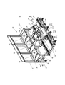
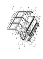
- the pallet supply device 1 of this example is composed of a transfer device 10, a pallet accommodating device 30, a control device 60, and the like.
- the transport device 10 travels on a travel base 11 having a travel path 11a for transporting the pallet P to and from a predetermined location (supply location), and travels on the travel path 11a, and accommodates the pallet.
- the pallet P is taken in and out of the apparatus 30, and the pallet P is conveyed to and from the supply place.
- the traveling base 11 is arranged so as to connect the pallet accommodating device 30 and the supply location, but only a part thereof is shown in FIGS. 1 to 4.
- the traveling base 11 is a member having a U-shaped cross section, and guide rails 12 are arranged on the parallel upper surfaces of the traveling base 11. Then, the guide rail 12 forms a traveling path 11a along the arrow directions AB.
- the transport unit 15 is mounted on the guide rails 12 so as to straddle the pair of guide rails 12 via a slider (not shown), and the traveling carriage 16 is movable in the directions AB.
- a moving mechanism 17 for moving the traveling carriage 16 in the direction of arrows AB, and a transfer mechanism 20 provided on the traveling carriage 16 are provided.
- the traveling carriage 16 can be moved in the directions AB as described above, and various conventionally known mechanisms can be applied.
- the traveling bases 11. It can be composed of a rack fixed on the wall surface along the longitudinal direction thereof, a pinion gear provided on the traveling carriage 16 and meshing with the rack, a drive motor 17a for driving the pinion gear, and the like.
- the traveling bogie 16 by rotating the pinion gear by the drive motor 17a, the traveling bogie 16 moves in the direction of arrows AB due to the meshing relationship with the rack.
- the transfer mechanism 20 is composed of a base member 22, a first slide member 23, and a second slide member 24 arranged so as to be sequentially overlapped with each other, and is configured to expand and contract toward the pallet accommodating device 30. 21, an expansion / contraction drive unit (not shown) that expands / contracts the expansion / contraction portion 21, a support portion 24a provided on the second slide member 24 that supports the pallet P, and an elevating drive that raises and lowers the support portion 24a. It is composed of parts (not shown).
- the control device 60 controls the operation of the moving mechanism 17 and the transfer mechanism 20, and is arranged in the gantry 40 of the pallet accommodating device 30, which will be described in detail later.
- the pallet accommodating device 30 is located below the holding plates 34, 35, 36, 37 juxtaposed along the traveling base 11 and between the holding plates 34, 35, 36, 37, respectively, and travels.
- Plate-shaped inclined covers 42, 47, 50 arranged on the rear side, which is a side away from the base 11, and similarly plate-shaped flip-up covers arranged on the front side, which is the traveling base 11 side.
- 43, 48, 51 a frame-shaped (frame-shaped) pedestal 40 that supports these holding plates 34, 35, 36, 37, inclined covers 42, 47, 50, and flip-up covers 43, 48, 51, and this pedestal. It is composed of an outer wall 41 or the like provided on the rear side of the 40.
- the holding plates 34, 35, 36, 37 function as holding portions for holding the pallet P, the holding plates 34, 35 form the holding portion 31, and the holding plates 35, 36 form the holding portion 32. , Holding plates 36, 37 form the holding portion 33. Then, the pallet P is placed on these in the holding portion 31 so as to straddle the holding plates 34 and 35, and similarly, in the holding portion 32, on these so as to straddle the holding plates 35 and 36. It is placed and placed on the holding plates 33 and 37 so as to straddle the holding plates 36 and 37.
- the traveling carriage 16 is moved in the direction of arrow AB by the moving mechanism 17, and is positioned at a position corresponding to each of the holding portions 31, 32 and 33, respectively. Then, at the positions corresponding to the holding portions 31, 32 and 33, the transfer mechanism 20 carries the pallet P into the holding portions 31, 32 and 33, and also carries the pallets P into the holding portions 31, 32 and 33. The pallet P held in the above is carried out onto the traveling carriage 16.
- the transfer mechanism 20 raises and lowers the support portion 24a that supports the pallet P by an elevating drive portion (not shown).
- the first slide member 23 and the second slide member 24 are extended to move the pallet P above the holding plates 35 and 36 (holding portion 32), and then the elevating drive portion (shown).
- the elevating drive portion shown.
- the pallet P is placed on the holding plates 35 and 36 (holding portion 32), and then the first slide member 23 and the second slide member 24 are contracted. As a result, the pallet P is carried into the holding portion 32.
- the transfer mechanism 20 raises and lowers the support portion 24a in a state where the pallet P is not supported (not shown).
- the first slide member 23 and the second slide member 24 are extended so that the support portion 24a is placed below the pallet P placed on the holding plates 35 and 36 (holding portions 32).
- the elevating drive unit By moving the pallet P and then raising the support portion 24a by the elevating drive unit (not shown), the pallet P is supported by the support portion 24a above the holding plates 35 and 36 (holding portion 32). After floating, the pallet P is carried out onto the traveling carriage 16 by contracting the first slide member 23 and the second slide member 24.
- the inclined covers 42, 47, 50 and the flip-up covers 43, 48, 51 are provided so as to be inclined downward toward the oil recovery passage 11b formed in the traveling base 11, respectively. Then, the upper end upper surface of the flip-up cover 43 is connected to the lower end lower surface of the inclined cover 42, and similarly, the upper end upper surface of the flip-up cover 48 is connected to the lower end lower surface of the inclined cover 47, and the upper end of the flip-up cover 51 is connected. The upper surface is connected to the lower end lower surface of the inclined cover 50.
- the lower ends of the flip-up covers 43, 48, and 51 are located above the oil recovery passage 11b of the traveling base 11, respectively.
- These inclined covers 42, 47, 50 and flip-up covers 43, 48, 51 function as oil recovery plates, and oil or the like (chips, etc.) dripping from the pallets P placed on the holding portions 31, 32, 33. To the oil recovery passage 11b).
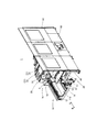
- both sides of the flip-up cover 43 are attached to the gantry 40 via a pair of support stays 44 pivotally supported by the gantry 40, and similarly, the flip-up cover 48 has both side portions thereof.
- the flip-up cover 51 is attached to the gantry 40 via a pair of support stays 49 pivotally supported by the gantry 40, and both sides of the flip-up cover 51 are pivotally supported by the gantry 40 via a pair of support stays 52. It is attached to the gantry 40.
- the flip-up covers 43, 48, 51 have their lower end rotatable in the vertical direction with the shaft support portions of the support stays 44, 49, 52 as fulcrums.
- the flip-up cover 48 is rotatable in the vertical direction (in the direction of arrow CD) with the shaft support portion (49a) of the support stay 49 as a fulcrum. ..
- each of the flip-up covers 43, 48, 51 is maintained in a state in which the lower end side thereof is flipped up by the locking tool engaged with the gantry 40.
- Various types of locking tools can be applied, but in this example, as shown in FIG. 5, the locking bolt 49b screwed to the pillar portion of the gantry 40 is applied, and in FIG. 5, the bounce is applied.
- the locking bolt 49b With the raising cover 48 flipped up, the locking bolt 49b is screwed onto the pillar portion of the gantry 40 to penetrate the pillar portion, so that the lower end portion of the flip-up cover 48 is supported by the locking bolt 49b.
- the flip-up state is maintained.
- the flip-up cover 48 can rotate downward.
- the control device 60 can pass under the flip-up covers 43, 48, 51. It has become. Further, in this example, the control device 60 is installed at a position below the holding portions 32 and 33.
- the traveling base 11 can be adjusted to a horizontal level by a jack bolt 13.
- the gantry 40 is provided with a plurality of casters 55 on the lower surface thereof, and can be manually transported by the casters 55, and similarly, the height thereof is increased by the plurality of stands 56 provided on the lower surface thereof. It can be installed on the floor surface with its position adjusted (at this time, the caster 55 is raised upward from the floor surface).
- control device 60 can be manually conveyed by a plurality of casters 61 provided on the lower surface thereof, and similarly, the height position thereof is determined by a plurality of stands 62 provided on the lower surface thereof. In the adjusted state, it can be installed on the floor surface (at this time, the caster 61 is raised upward from the floor surface).
- the traveling carriage 16 is driven by the moving mechanism 17 under the control of the control device 60, and the traveling carriage 16 is the traveling base 11.
- the pallet P is appropriately supplied to the supply location and collected from the supply location by traveling in the direction of arrow AB along the traveling path 11a formed above. P is accommodated in the pallet accommodating device 30.
- the pallet supply device 1 of this example of this example for example, when installing this in a factory, it is assembled and installed as follows.
- the gantry 40 and the control device 60 can be manually transported by the casters 55 and 61, respectively.
- the control device 60 is manually transported and temporarily placed in the vicinity of the traveling base 11. Then, the moving mechanism 17, the transfer mechanism 20, and the control device 60 are electrically connected.
- a carrier such as a forklift or a handlift can be used to install the traveling base 11.
- the flip-up cover 48 is flipped upward, and the locking bolt 49b is screwed to the gantry 40 to maintain the flip-up cover 48 in the flip-up state, and then the gantry 40 is attached to the gantry 40.
- the control device 60 is brought close to the traveling base 11 from the control device 60 side so as to pass relatively below the flip-up cover 48, and is juxtaposed with the traveling base 11 (FIGS. 3 to 3). 5).
- control device 60 is swiveled and its position is adjusted to move it to a regular position set below the holding portions 32 and 33 of the gantry 40, and then the locking bolt 49b is placed on the gantry 40.
- the flip-up cover 48 is returned from the flip-up state to the original downward tilted state.
- the stands 56 and 62 are adjusted to support the gantry 40 and the control device 60 by these stands 56 and 62, and the height positions of the respective stands are adjusted.
- the transport device 10, the pallet accommodating device 30, and the control device 60 can be installed at the set positions.
- the control device 60 is housed in the space provided in the gantry 40 of the pallet storage device 30 without using a hoisting device such as an overhead crane.
- the transport device 10, the pallet accommodating device 30, and the control device 60 can be assembled. Therefore, the pallet supply device 1 can be easily installed even in a factory where a hoisting device such as an overhead crane is not prepared.
- the braking performance of the control device 60 when the control device 60 is housed in the space of the gantry 40 is better than that in the case of using the hoisting device, the interference between the control device 60 and the gantry 40 can be easily achieved. This can be avoided, and the installation work of the gantry 40 and the control device 60 can be easily and in a short time.
- the flip-up covers 43, 48, 51 are configured to be flipped upward (in the direction of arrow C) and to maintain this flip-up state. Therefore, for example, maintenance of the lower positions of the holding portions 31, 32, 33 and maintenance of the control device 60 can be performed from the traveling base 11 side, and the maintenance and maintenance can be easily performed. If the flip-up covers 43, 48, 51 are not provided so that they can be flipped up, it is necessary to perform maintenance and maintenance with the outer wall 41 attached to the gantry 40 removed, which is complicated. It will be a thing.
- holding portions 31, 32, 33 are set as holding portions for holding the pallet, but the number of holding portions to be installed is not limited to this, and more than this, as a matter of course. However, the number may be less than this.
- the holding portion is provided on one side along the traveling track 11, but the present invention is not limited to such a configuration, and holding portions may be provided on both sides of the traveling track 11.
Landscapes
- Engineering & Computer Science (AREA)
- Mechanical Engineering (AREA)
- Warehouses Or Storage Devices (AREA)
- Auxiliary Devices For Machine Tools (AREA)
- Feeding Of Workpieces (AREA)
- Machine Tool Units (AREA)
- Intermediate Stations On Conveyors (AREA)
Priority Applications (5)
| Application Number | Priority Date | Filing Date | Title |
|---|---|---|---|
| PCT/JP2020/019874 WO2021234834A1 (ja) | 2020-05-20 | 2020-05-20 | パレット供給装置 |
| CN202080101017.XA CN115666844B (zh) | 2020-05-20 | 2020-05-20 | 托盘提供装置 |
| JP2022524737A JP7467618B2 (ja) | 2020-05-20 | 2020-05-20 | パレット供給装置 |
| EP20936583.2A EP4140639B1 (en) | 2020-05-20 | 2020-05-20 | Pallet supply apparatus and mtehod of assembling a pallet supply apparatus |
| US17/926,299 US12420369B2 (en) | 2020-05-20 | 2020-05-20 | Pallet supply apparatus |
Applications Claiming Priority (1)
| Application Number | Priority Date | Filing Date | Title |
|---|---|---|---|
| PCT/JP2020/019874 WO2021234834A1 (ja) | 2020-05-20 | 2020-05-20 | パレット供給装置 |
Publications (1)
| Publication Number | Publication Date |
|---|---|
| WO2021234834A1 true WO2021234834A1 (ja) | 2021-11-25 |
Family
ID=78708271
Family Applications (1)
| Application Number | Title | Priority Date | Filing Date |
|---|---|---|---|
| PCT/JP2020/019874 Ceased WO2021234834A1 (ja) | 2020-05-20 | 2020-05-20 | パレット供給装置 |
Country Status (5)
| Country | Link |
|---|---|
| US (1) | US12420369B2 (https=) |
| EP (1) | EP4140639B1 (https=) |
| JP (1) | JP7467618B2 (https=) |
| CN (1) | CN115666844B (https=) |
| WO (1) | WO2021234834A1 (https=) |
Cited By (1)
| Publication number | Priority date | Publication date | Assignee | Title |
|---|---|---|---|---|
| TWI903989B (zh) * | 2025-01-23 | 2025-11-01 | 卓金星 | 水平調整平台 |
Citations (7)
| Publication number | Priority date | Publication date | Assignee | Title |
|---|---|---|---|---|
| JPS6179544A (ja) * | 1984-09-28 | 1986-04-23 | Hitachi Seiki Co Ltd | 無人搬送台車 |
| JPH0240728U (https=) * | 1988-09-07 | 1990-03-20 | ||
| JPH04106149U (ja) * | 1991-02-27 | 1992-09-11 | 日立精機株式会社 | Fmsのパレツトおよびワークの搬送装置 |
| JPH06262495A (ja) * | 1993-03-16 | 1994-09-20 | Toyoda Mach Works Ltd | 数値制御工作機械群の制御装置 |
| JPH0885032A (ja) * | 1994-09-14 | 1996-04-02 | Hitachi Ltd | フレキシブル生産システム |
| JP2014083670A (ja) | 2012-10-26 | 2014-05-12 | Makino J Kk | パレット搬送装置 |
| JP2020019119A (ja) * | 2018-08-03 | 2020-02-06 | 天竜精機株式会社 | ベースマシン |
Family Cites Families (30)
| Publication number | Priority date | Publication date | Assignee | Title |
|---|---|---|---|---|
| US3648819A (en) * | 1968-03-29 | 1972-03-14 | Scans Associates Inc | Industrial system and method |
| JPS6029262A (ja) * | 1983-07-25 | 1985-02-14 | Aioi Seiki Kk | 工作機械のワ−クパレット交換装置 |
| DE8606773U1 (de) * | 1986-03-12 | 1987-07-09 | Fa. Andreas Stihl, 7050 Waiblingen | Werkzeug-Übergabestation |
| US4747193A (en) * | 1986-05-20 | 1988-05-31 | Makino Milling Machine Co., Ltd. | Pallet supply apparatus for machine tool |
| US4928806A (en) * | 1988-04-08 | 1990-05-29 | Honeywell Inc. | System for removing a pallet from a moving transfer mechanism and for accurately locking the pallet at a precise location |
| EP0385261A1 (de) * | 1989-03-01 | 1990-09-05 | Blüco-Technik Blümle KG | Manuell betätigbare flexible Transport- oder Montageeinrichtung für Paletten |
| JPH03287331A (ja) * | 1990-04-02 | 1991-12-18 | Canon Inc | 物品供給方法 |
| JPH06155197A (ja) * | 1992-11-16 | 1994-06-03 | Pfu Ltd | 混流生産システムにおける部材供給システム |
| JPH06238551A (ja) * | 1993-01-21 | 1994-08-30 | Murata Mach Ltd | 工作機械の生産管理システム |
| US5346051A (en) * | 1993-07-29 | 1994-09-13 | Midaco Corporation | Quick change-over pallet system |
| JPH07290166A (ja) * | 1994-04-28 | 1995-11-07 | Anritsu Corp | 板金搬送加工装置 |
| US20080067035A1 (en) * | 2006-09-01 | 2008-03-20 | Keith Malcolm E | Automatic pallet changer |
| US20080271302A1 (en) * | 2007-05-03 | 2008-11-06 | Ann Arbor Machine Company | Machining center |
| CN201227737Y (zh) * | 2008-07-04 | 2009-04-29 | 台湾丽伟电脑机械股份有限公司 | 工具机的可折式操作箱 |
| KR101013969B1 (ko) * | 2008-08-25 | 2011-02-14 | 현대자동차주식회사 | 이송 대차 순환 시스템 |
| EP2403784B1 (en) * | 2009-03-03 | 2013-07-24 | ATS Automation Tooling Systems Inc. | Multi-mode scroll cam conveyor system |
| JP5686400B2 (ja) * | 2010-03-12 | 2015-03-18 | 日特エンジニアリング株式会社 | パレット搬送装置 |
| JP2011224742A (ja) * | 2010-04-21 | 2011-11-10 | Canon Inc | ロボットセル |
| EP2708312B1 (en) * | 2012-06-15 | 2014-12-17 | Yamazaki Mazak Corporation | Machining center |
| JP6427866B2 (ja) * | 2013-11-19 | 2018-11-28 | 株式会社ジェイテクト | フレキシブル生産システム |
| JP6596649B2 (ja) * | 2014-11-14 | 2019-10-30 | パナソニックIpマネジメント株式会社 | トレイフィーダ及び部品実装装置 |
| JP6463460B2 (ja) * | 2015-03-26 | 2019-02-06 | 株式会社Fuji | キャスタ付移動式架台及び加工機械ライン |
| JP6615067B2 (ja) * | 2015-09-08 | 2019-12-04 | Nittoku株式会社 | パレット搬送装置 |
| JP6813271B2 (ja) * | 2016-03-03 | 2021-01-13 | 株式会社Subaru | ワーク搬送システム及びワーク加工方法 |
| WO2018216237A1 (ja) * | 2017-09-06 | 2018-11-29 | 平田機工株式会社 | 作業装置及び作業システム |
| US11052498B2 (en) * | 2018-05-14 | 2021-07-06 | Modig Machine Tool US Inc. | Invertible part loading system |
| CN109305387B (zh) | 2018-10-31 | 2024-05-28 | 成都航空职业技术学院 | 一种飞机机轮自动化拆装设备及自动化拆装方法 |
| JP6688912B1 (ja) | 2019-01-11 | 2020-04-28 | Dmg森精機株式会社 | パレット搬送システム、パレット搬送方法、および、パレット搬送プログラム |
| JP7410615B2 (ja) * | 2019-09-03 | 2024-01-10 | キヤノン株式会社 | 加工システム、および物品の製造方法 |
| US20220111475A1 (en) * | 2020-10-09 | 2022-04-14 | Midaco Corporation | Delivery apparatus for moving workpieces |
-
2020
- 2020-05-20 EP EP20936583.2A patent/EP4140639B1/en active Active
- 2020-05-20 US US17/926,299 patent/US12420369B2/en active Active
- 2020-05-20 JP JP2022524737A patent/JP7467618B2/ja active Active
- 2020-05-20 CN CN202080101017.XA patent/CN115666844B/zh active Active
- 2020-05-20 WO PCT/JP2020/019874 patent/WO2021234834A1/ja not_active Ceased
Patent Citations (7)
| Publication number | Priority date | Publication date | Assignee | Title |
|---|---|---|---|---|
| JPS6179544A (ja) * | 1984-09-28 | 1986-04-23 | Hitachi Seiki Co Ltd | 無人搬送台車 |
| JPH0240728U (https=) * | 1988-09-07 | 1990-03-20 | ||
| JPH04106149U (ja) * | 1991-02-27 | 1992-09-11 | 日立精機株式会社 | Fmsのパレツトおよびワークの搬送装置 |
| JPH06262495A (ja) * | 1993-03-16 | 1994-09-20 | Toyoda Mach Works Ltd | 数値制御工作機械群の制御装置 |
| JPH0885032A (ja) * | 1994-09-14 | 1996-04-02 | Hitachi Ltd | フレキシブル生産システム |
| JP2014083670A (ja) | 2012-10-26 | 2014-05-12 | Makino J Kk | パレット搬送装置 |
| JP2020019119A (ja) * | 2018-08-03 | 2020-02-06 | 天竜精機株式会社 | ベースマシン |
Non-Patent Citations (1)
| Title |
|---|
| See also references of EP4140639A4 |
Cited By (1)
| Publication number | Priority date | Publication date | Assignee | Title |
|---|---|---|---|---|
| TWI903989B (zh) * | 2025-01-23 | 2025-11-01 | 卓金星 | 水平調整平台 |
Also Published As
| Publication number | Publication date |
|---|---|
| EP4140639A1 (en) | 2023-03-01 |
| CN115666844A (zh) | 2023-01-31 |
| EP4140639C0 (en) | 2024-10-02 |
| EP4140639B1 (en) | 2024-10-02 |
| JPWO2021234834A1 (https=) | 2021-11-25 |
| CN115666844B (zh) | 2025-07-29 |
| JP7467618B2 (ja) | 2024-04-15 |
| EP4140639A4 (en) | 2023-12-27 |
| US12420369B2 (en) | 2025-09-23 |
| US20230211950A1 (en) | 2023-07-06 |
Similar Documents
| Publication | Publication Date | Title |
|---|---|---|
| KR101198662B1 (ko) | 자동차용 사이드패널 생산시스템 | |
| RU2463193C2 (ru) | Транспортирующее устройство с использованием тележки | |
| JPH0411326B2 (https=) | ||
| KR100743194B1 (ko) | 이송시스템 | |
| CN103384583A (zh) | 机床的随行夹具输送装置 | |
| CN105592976A (zh) | 机床设备 | |
| JP5429787B2 (ja) | 組立搬送設備 | |
| WO2021234834A1 (ja) | パレット供給装置 | |
| JP5579242B2 (ja) | パレット搬送装置 | |
| JP6574813B2 (ja) | 床下機器着脱装置 | |
| JP2002263888A (ja) | 配材装置および鋼構造物組立設備 | |
| JP2007137254A (ja) | 走行台車搭載ロボットの搬送台車 | |
| JP3769073B2 (ja) | 物品の移載機 | |
| JPS62218305A (ja) | 自動車ボデイのリフテイング台車 | |
| JPH08217211A (ja) | 盤製造装置 | |
| JP5131787B2 (ja) | 自動搬送車 | |
| JP2580328B2 (ja) | 昇降作業台付き搬送装置 | |
| KR101836474B1 (ko) | 모듈형 이송장치 | |
| JP3649030B2 (ja) | ワーク搬送装置 | |
| KR102433508B1 (ko) | 리프팅장치 | |
| JPH09155528A (ja) | 金型段取り装置 | |
| JPH0784320B2 (ja) | 昇降作業台 | |
| JP4650680B2 (ja) | 搬送設備 | |
| JPH07115310B2 (ja) | 昇降作業台のセンタリング装置 | |
| JP5268252B2 (ja) | ローリフトトラック |
Legal Events
| Date | Code | Title | Description |
|---|---|---|---|
| 121 | Ep: the epo has been informed by wipo that ep was designated in this application |
Ref document number: 20936583 Country of ref document: EP Kind code of ref document: A1 |
|
| ENP | Entry into the national phase |
Ref document number: 2022524737 Country of ref document: JP Kind code of ref document: A |
|
| ENP | Entry into the national phase |
Ref document number: 2020936583 Country of ref document: EP Effective date: 20221125 |
|
| NENP | Non-entry into the national phase |
Ref country code: DE |
|
| WWG | Wipo information: grant in national office |
Ref document number: 202080101017.X Country of ref document: CN |
|
| WWG | Wipo information: grant in national office |
Ref document number: 17926299 Country of ref document: US |