WO2021085383A1 - 熱伝導性シート及びその製造方法 - Google Patents
熱伝導性シート及びその製造方法 Download PDFInfo
- Publication number
- WO2021085383A1 WO2021085383A1 PCT/JP2020/040121 JP2020040121W WO2021085383A1 WO 2021085383 A1 WO2021085383 A1 WO 2021085383A1 JP 2020040121 W JP2020040121 W JP 2020040121W WO 2021085383 A1 WO2021085383 A1 WO 2021085383A1
- Authority
- WO
- WIPO (PCT)
- Prior art keywords
- filler
- conductive sheet
- scaly
- heat conductive
- axis direction
- Prior art date
- Legal status (The legal status is an assumption and is not a legal conclusion. Google has not performed a legal analysis and makes no representation as to the accuracy of the status listed.)
- Ceased
Links
Images


Classifications
-
- H—ELECTRICITY
- H10—SEMICONDUCTOR DEVICES; ELECTRIC SOLID-STATE DEVICES NOT OTHERWISE PROVIDED FOR
- H10W—GENERIC PACKAGES, INTERCONNECTIONS, CONNECTORS OR OTHER CONSTRUCTIONAL DETAILS OF DEVICES COVERED BY CLASS H10
- H10W40/00—Arrangements for thermal protection or thermal control
- H10W40/20—Arrangements for cooling
- H10W40/25—Arrangements for cooling characterised by their materials
- H10W40/251—Organics
-
- C—CHEMISTRY; METALLURGY
- C08—ORGANIC MACROMOLECULAR COMPOUNDS; THEIR PREPARATION OR CHEMICAL WORKING-UP; COMPOSITIONS BASED THEREON
- C08J—WORKING-UP; GENERAL PROCESSES OF COMPOUNDING; AFTER-TREATMENT NOT COVERED BY SUBCLASSES C08B, C08C, C08F, C08G or C08H
- C08J5/00—Manufacture of articles or shaped materials containing macromolecular substances
- C08J5/18—Manufacture of films or sheets
-
- B—PERFORMING OPERATIONS; TRANSPORTING
- B32—LAYERED PRODUCTS
- B32B—LAYERED PRODUCTS, i.e. PRODUCTS BUILT-UP OF STRATA OF FLAT OR NON-FLAT, e.g. CELLULAR OR HONEYCOMB, FORM
- B32B38/00—Ancillary operations in connection with laminating processes
- B32B38/0004—Cutting, tearing or severing, e.g. bursting; Cutter details
-
- B—PERFORMING OPERATIONS; TRANSPORTING
- B29—WORKING OF PLASTICS; WORKING OF SUBSTANCES IN A PLASTIC STATE IN GENERAL
- B29C—SHAPING OR JOINING OF PLASTICS; SHAPING OF MATERIAL IN A PLASTIC STATE, NOT OTHERWISE PROVIDED FOR; AFTER-TREATMENT OF THE SHAPED PRODUCTS, e.g. REPAIRING
- B29C70/00—Shaping composites, i.e. plastics material comprising reinforcements, fillers or preformed parts, e.g. inserts
- B29C70/58—Shaping composites, i.e. plastics material comprising reinforcements, fillers or preformed parts, e.g. inserts comprising fillers only, e.g. particles, powder, beads, flakes, spheres
- B29C70/62—Shaping composites, i.e. plastics material comprising reinforcements, fillers or preformed parts, e.g. inserts comprising fillers only, e.g. particles, powder, beads, flakes, spheres the filler being oriented during moulding
-
- B—PERFORMING OPERATIONS; TRANSPORTING
- B29—WORKING OF PLASTICS; WORKING OF SUBSTANCES IN A PLASTIC STATE IN GENERAL
- B29C—SHAPING OR JOINING OF PLASTICS; SHAPING OF MATERIAL IN A PLASTIC STATE, NOT OTHERWISE PROVIDED FOR; AFTER-TREATMENT OF THE SHAPED PRODUCTS, e.g. REPAIRING
- B29C70/00—Shaping composites, i.e. plastics material comprising reinforcements, fillers or preformed parts, e.g. inserts
- B29C70/88—Shaping composites, i.e. plastics material comprising reinforcements, fillers or preformed parts, e.g. inserts characterised primarily by possessing specific properties, e.g. electrically conductive or locally reinforced
-
- B—PERFORMING OPERATIONS; TRANSPORTING
- B32—LAYERED PRODUCTS
- B32B—LAYERED PRODUCTS, i.e. PRODUCTS BUILT-UP OF STRATA OF FLAT OR NON-FLAT, e.g. CELLULAR OR HONEYCOMB, FORM
- B32B27/00—Layered products comprising a layer of synthetic resin
- B32B27/06—Layered products comprising a layer of synthetic resin as the main or only constituent of a layer, which is next to another layer of the same or of a different material
- B32B27/08—Layered products comprising a layer of synthetic resin as the main or only constituent of a layer, which is next to another layer of the same or of a different material of synthetic resin
-
- B—PERFORMING OPERATIONS; TRANSPORTING
- B32—LAYERED PRODUCTS
- B32B—LAYERED PRODUCTS, i.e. PRODUCTS BUILT-UP OF STRATA OF FLAT OR NON-FLAT, e.g. CELLULAR OR HONEYCOMB, FORM
- B32B27/00—Layered products comprising a layer of synthetic resin
- B32B27/18—Layered products comprising a layer of synthetic resin characterised by the use of special additives
- B32B27/20—Layered products comprising a layer of synthetic resin characterised by the use of special additives using fillers, pigments, thixotroping agents
-
- C—CHEMISTRY; METALLURGY
- C09—DYES; PAINTS; POLISHES; NATURAL RESINS; ADHESIVES; COMPOSITIONS NOT OTHERWISE PROVIDED FOR; APPLICATIONS OF MATERIALS NOT OTHERWISE PROVIDED FOR
- C09K—MATERIALS FOR MISCELLANEOUS APPLICATIONS, NOT PROVIDED FOR ELSEWHERE
- C09K5/00—Heat-transfer, heat-exchange or heat-storage materials, e.g. refrigerants; Materials for the production of heat or cold by chemical reactions other than by combustion
- C09K5/08—Materials not undergoing a change of physical state when used
- C09K5/14—Solid materials, e.g. powdery or granular
-
- H—ELECTRICITY
- H10—SEMICONDUCTOR DEVICES; ELECTRIC SOLID-STATE DEVICES NOT OTHERWISE PROVIDED FOR
- H10W—GENERIC PACKAGES, INTERCONNECTIONS, CONNECTORS OR OTHER CONSTRUCTIONAL DETAILS OF DEVICES COVERED BY CLASS H10
- H10W40/00—Arrangements for thermal protection or thermal control
- H10W40/01—Manufacture or treatment
- H10W40/03—Manufacture or treatment of arrangements for cooling
- H10W40/037—Assembling together parts thereof
-
- H—ELECTRICITY
- H10—SEMICONDUCTOR DEVICES; ELECTRIC SOLID-STATE DEVICES NOT OTHERWISE PROVIDED FOR
- H10W—GENERIC PACKAGES, INTERCONNECTIONS, CONNECTORS OR OTHER CONSTRUCTIONAL DETAILS OF DEVICES COVERED BY CLASS H10
- H10W40/00—Arrangements for thermal protection or thermal control
- H10W40/20—Arrangements for cooling
- H10W40/25—Arrangements for cooling characterised by their materials
- H10W40/259—Ceramics or glasses
-
- B—PERFORMING OPERATIONS; TRANSPORTING
- B32—LAYERED PRODUCTS
- B32B—LAYERED PRODUCTS, i.e. PRODUCTS BUILT-UP OF STRATA OF FLAT OR NON-FLAT, e.g. CELLULAR OR HONEYCOMB, FORM
- B32B38/00—Ancillary operations in connection with laminating processes
- B32B2038/0052—Other operations not otherwise provided for
-
- B—PERFORMING OPERATIONS; TRANSPORTING
- B32—LAYERED PRODUCTS
- B32B—LAYERED PRODUCTS, i.e. PRODUCTS BUILT-UP OF STRATA OF FLAT OR NON-FLAT, e.g. CELLULAR OR HONEYCOMB, FORM
- B32B2250/00—Layers arrangement
- B32B2250/24—All layers being polymeric
-
- B—PERFORMING OPERATIONS; TRANSPORTING
- B32—LAYERED PRODUCTS
- B32B—LAYERED PRODUCTS, i.e. PRODUCTS BUILT-UP OF STRATA OF FLAT OR NON-FLAT, e.g. CELLULAR OR HONEYCOMB, FORM
- B32B2250/00—Layers arrangement
- B32B2250/44—Number of layers variable across the laminate
-
- B—PERFORMING OPERATIONS; TRANSPORTING
- B32—LAYERED PRODUCTS
- B32B—LAYERED PRODUCTS, i.e. PRODUCTS BUILT-UP OF STRATA OF FLAT OR NON-FLAT, e.g. CELLULAR OR HONEYCOMB, FORM
- B32B2262/00—Composition or structural features of fibres which form a fibrous or filamentary layer or are present as additives
- B32B2262/10—Inorganic fibres
- B32B2262/106—Carbon fibres, e.g. graphite fibres
-
- B—PERFORMING OPERATIONS; TRANSPORTING
- B32—LAYERED PRODUCTS
- B32B—LAYERED PRODUCTS, i.e. PRODUCTS BUILT-UP OF STRATA OF FLAT OR NON-FLAT, e.g. CELLULAR OR HONEYCOMB, FORM
- B32B2264/00—Composition or properties of particles which form a particulate layer or are present as additives
- B32B2264/10—Inorganic particles
- B32B2264/102—Oxide or hydroxide
-
- B—PERFORMING OPERATIONS; TRANSPORTING
- B32—LAYERED PRODUCTS
- B32B—LAYERED PRODUCTS, i.e. PRODUCTS BUILT-UP OF STRATA OF FLAT OR NON-FLAT, e.g. CELLULAR OR HONEYCOMB, FORM
- B32B2264/00—Composition or properties of particles which form a particulate layer or are present as additives
- B32B2264/10—Inorganic particles
- B32B2264/107—Ceramic
- B32B2264/108—Carbon, e.g. graphite particles
-
- B—PERFORMING OPERATIONS; TRANSPORTING
- B32—LAYERED PRODUCTS
- B32B—LAYERED PRODUCTS, i.e. PRODUCTS BUILT-UP OF STRATA OF FLAT OR NON-FLAT, e.g. CELLULAR OR HONEYCOMB, FORM
- B32B2264/00—Composition or properties of particles which form a particulate layer or are present as additives
- B32B2264/30—Particles characterised by physical dimension
- B32B2264/303—Average diameter greater than 1µm
-
- B—PERFORMING OPERATIONS; TRANSPORTING
- B32—LAYERED PRODUCTS
- B32B—LAYERED PRODUCTS, i.e. PRODUCTS BUILT-UP OF STRATA OF FLAT OR NON-FLAT, e.g. CELLULAR OR HONEYCOMB, FORM
- B32B2264/00—Composition or properties of particles which form a particulate layer or are present as additives
- B32B2264/30—Particles characterised by physical dimension
- B32B2264/308—Aspect ratio of particles
-
- B—PERFORMING OPERATIONS; TRANSPORTING
- B32—LAYERED PRODUCTS
- B32B—LAYERED PRODUCTS, i.e. PRODUCTS BUILT-UP OF STRATA OF FLAT OR NON-FLAT, e.g. CELLULAR OR HONEYCOMB, FORM
- B32B2305/00—Condition, form or state of the layers or laminate
- B32B2305/30—Fillers, e.g. particles, powders, beads, flakes, spheres, chips
-
- B—PERFORMING OPERATIONS; TRANSPORTING
- B32—LAYERED PRODUCTS
- B32B—LAYERED PRODUCTS, i.e. PRODUCTS BUILT-UP OF STRATA OF FLAT OR NON-FLAT, e.g. CELLULAR OR HONEYCOMB, FORM
- B32B2307/00—Properties of the layers or laminate
- B32B2307/30—Properties of the layers or laminate having particular thermal properties
- B32B2307/302—Conductive
-
- B—PERFORMING OPERATIONS; TRANSPORTING
- B32—LAYERED PRODUCTS
- B32B—LAYERED PRODUCTS, i.e. PRODUCTS BUILT-UP OF STRATA OF FLAT OR NON-FLAT, e.g. CELLULAR OR HONEYCOMB, FORM
- B32B2307/00—Properties of the layers or laminate
- B32B2307/70—Other properties
- B32B2307/732—Dimensional properties
-
- B—PERFORMING OPERATIONS; TRANSPORTING
- B32—LAYERED PRODUCTS
- B32B—LAYERED PRODUCTS, i.e. PRODUCTS BUILT-UP OF STRATA OF FLAT OR NON-FLAT, e.g. CELLULAR OR HONEYCOMB, FORM
- B32B2313/00—Elements other than metals
- B32B2313/02—Boron
-
- C—CHEMISTRY; METALLURGY
- C08—ORGANIC MACROMOLECULAR COMPOUNDS; THEIR PREPARATION OR CHEMICAL WORKING-UP; COMPOSITIONS BASED THEREON
- C08J—WORKING-UP; GENERAL PROCESSES OF COMPOUNDING; AFTER-TREATMENT NOT COVERED BY SUBCLASSES C08B, C08C, C08F, C08G or C08H
- C08J2383/00—Characterised by the use of macromolecular compounds obtained by reactions forming in the main chain of the macromolecule a linkage containing silicon with or without sulfur, nitrogen, oxygen, or carbon only; Derivatives of such polymers
- C08J2383/04—Polysiloxanes
- C08J2383/07—Polysiloxanes containing silicon bound to unsaturated aliphatic groups
-
- C—CHEMISTRY; METALLURGY
- C08—ORGANIC MACROMOLECULAR COMPOUNDS; THEIR PREPARATION OR CHEMICAL WORKING-UP; COMPOSITIONS BASED THEREON
- C08J—WORKING-UP; GENERAL PROCESSES OF COMPOUNDING; AFTER-TREATMENT NOT COVERED BY SUBCLASSES C08B, C08C, C08F, C08G or C08H
- C08J2483/00—Characterised by the use of macromolecular compounds obtained by reactions forming in the main chain of the macromolecule a linkage containing silicon with or without sulfur, nitrogen, oxygen, or carbon only; Derivatives of such polymers
- C08J2483/04—Polysiloxanes
- C08J2483/05—Polysiloxanes containing silicon bound to hydrogen
-
- C—CHEMISTRY; METALLURGY
- C08—ORGANIC MACROMOLECULAR COMPOUNDS; THEIR PREPARATION OR CHEMICAL WORKING-UP; COMPOSITIONS BASED THEREON
- C08K—Use of inorganic or non-macromolecular organic substances as compounding ingredients
- C08K3/00—Use of inorganic substances as compounding ingredients
- C08K3/18—Oxygen-containing compounds, e.g. metal carbonyls
- C08K3/20—Oxides; Hydroxides
- C08K3/22—Oxides; Hydroxides of metals
- C08K2003/2227—Oxides; Hydroxides of metals of aluminium
-
- C—CHEMISTRY; METALLURGY
- C08—ORGANIC MACROMOLECULAR COMPOUNDS; THEIR PREPARATION OR CHEMICAL WORKING-UP; COMPOSITIONS BASED THEREON
- C08K—Use of inorganic or non-macromolecular organic substances as compounding ingredients
- C08K3/00—Use of inorganic substances as compounding ingredients
- C08K3/38—Boron-containing compounds
- C08K2003/382—Boron-containing compounds and nitrogen
- C08K2003/385—Binary compounds of nitrogen with boron
-
- C—CHEMISTRY; METALLURGY
- C08—ORGANIC MACROMOLECULAR COMPOUNDS; THEIR PREPARATION OR CHEMICAL WORKING-UP; COMPOSITIONS BASED THEREON
- C08K—Use of inorganic or non-macromolecular organic substances as compounding ingredients
- C08K3/00—Use of inorganic substances as compounding ingredients
- C08K3/02—Elements
- C08K3/04—Carbon
-
- C—CHEMISTRY; METALLURGY
- C08—ORGANIC MACROMOLECULAR COMPOUNDS; THEIR PREPARATION OR CHEMICAL WORKING-UP; COMPOSITIONS BASED THEREON
- C08K—Use of inorganic or non-macromolecular organic substances as compounding ingredients
- C08K7/00—Use of ingredients characterised by shape
-
- C—CHEMISTRY; METALLURGY
- C08—ORGANIC MACROMOLECULAR COMPOUNDS; THEIR PREPARATION OR CHEMICAL WORKING-UP; COMPOSITIONS BASED THEREON
- C08K—Use of inorganic or non-macromolecular organic substances as compounding ingredients
- C08K7/00—Use of ingredients characterised by shape
- C08K7/02—Fibres or whiskers
- C08K7/04—Fibres or whiskers inorganic
- C08K7/06—Elements
-
- C—CHEMISTRY; METALLURGY
- C08—ORGANIC MACROMOLECULAR COMPOUNDS; THEIR PREPARATION OR CHEMICAL WORKING-UP; COMPOSITIONS BASED THEREON
- C08K—Use of inorganic or non-macromolecular organic substances as compounding ingredients
- C08K7/00—Use of ingredients characterised by shape
- C08K7/16—Solid spheres
- C08K7/18—Solid spheres inorganic
Definitions
- the present invention relates to a thermally conductive sheet and a method for producing the same.
- a heat sink such as a heat sink is generally used to dissipate heat generated from a heating element such as a semiconductor element or a mechanical part.
- a heat conductive sheet is arranged between a heating element and a heat radiating element for the purpose of increasing the heat transfer efficiency to the heat radiating element.
- the heat conductive sheet generally contains a polymer matrix and a heat conductive filler dispersed in the polymer matrix. Further, in the heat conductive sheet, in order to enhance the heat conductivity in a specific direction, an anisotropic filler having anisotropy in shape may be oriented in one direction.
- the thermally conductive sheet in which the anisotropic filler is oriented in one direction includes, for example, a plurality of primary sheets in which the anisotropic filler such as a fibrous filler is oriented along the sheet surface direction by stretching or the like. It is manufactured by vertically slicing a product obtained by laminating a plurality of primary sheets and integrating them. According to this manufacturing method (hereinafter, also referred to as “fluid orientation method”), a thermally conductive sheet formed by laminating a large number of unit layers having a small thickness can be obtained. Further, the anisotropic filler can be oriented in the thickness direction of the sheet, and the thermal conductivity in the thickness direction becomes good (see, for example, Patent Document 1). Since the heat conductive sheet has high heat conductivity in the thickness direction, it is possible to efficiently dissipate the heat generated by the heating element to the outside inside the electronic device.
- a heat spot where the temperature rises locally may occur inside an electronic device.
- a heat diffusion sheet having excellent thermal conductivity in the surface direction may be used.
- the heat resistance of an electronic element generally differs depending on the type of the electronic element, for example, when an element having a low heat resistance exists on a substrate, it is necessary to prevent heat transfer in that direction. In that case, it is required to increase the thermal conductivity in a specific direction in the plane, while decreasing the thermal conductivity in a direction other than that direction.
- the conventional heat diffusion sheet is inferior in thermal conductivity in the thickness direction, it is inferior in the efficiency of transferring the heat generated by the heating element to the radiator, and it diffuses the heat isotropically, so that the heat is diffused in a specific direction. It is difficult to suppress the heat conduction of.
- the heat conductive sheet obtained by the conventional flow orientation method or the like in which the anisotropic filler is oriented in the thickness direction of the sheet is excellent in the efficiency of transferring the heat generated by the heating element to the heating element, but the sheet. It is difficult to increase the thermal conductivity in the direction along the surface direction of.
- an object of the present invention is to provide a thermally conductive sheet having high thermal conductivity not only in the thickness direction of the sheet but also in one direction along the surface direction of the sheet.
- the present invention provides the following [1] to [12].
- [1] A thermally conductive sheet containing a scaly filler in a polymer matrix.
- the scaly filler is provided along one of a first direction in which the major axis direction of the scaly surface is the thickness direction of the heat conductive sheet and a second direction in which the scaly filler is perpendicular to the first direction.
- a heat conductive sheet in which the horizontal axis direction perpendicular to the long axis direction on the scale surface is oriented along the other of the first direction and the second direction.
- the scaly filler contains scaly boron nitride powder.
- the heat conductive sheet according to any one of the above [1] to [10] which further contains a non-anisotropic filler in the polymer matrix.
- thermoly conductive sheet having high thermal conductivity not only in the thickness direction of the sheet but also in one direction along the surface direction of the sheet.
- FIG. 1 is a schematic view of the heat conductive sheet 10 of the first embodiment
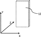
- FIG. 2 is a schematic view for explaining the details of the scaly filler 12.
- the thermally conductive sheet 10 according to the first embodiment includes a polymer matrix 11 and a scaly filler 12 dispersed in the polymer matrix 11.
- the length direction on the scaly surface is the major axis direction Y
- the direction perpendicular to the major axis direction on the scaly surface is the horizontal axis direction X
- these major axis directions Y is shown in the scaly filler 12
- the length direction on the scaly surface is the major axis direction Y
- the direction perpendicular to the major axis direction on the scaly surface is the horizontal axis direction X
- these major axis directions Y is shown in the scaly filler 12
- the length direction on the scaly surface is the major axis direction Y
- the scaly filler 12 is a thermally conductive filler that enhances the thermal conductivity of the thermally conductive sheet 10.
- the scaly filler 12 has a major axis direction Y along the first direction which is the thickness direction of the heat conductive sheet 10 and a horizontal axis direction X in the first direction. Oriented along a second direction that is vertical.
- the second direction is one direction in the surface direction of the sheet. Therefore, the heat conductive sheet 10 has good heat conductivity in one direction in the surface direction of the heat conductive sheet 10 in addition to the thickness direction.
- the direction perpendicular to both the first and second directions is defined as the third direction.
- the third direction is one direction along the surface direction of the heat conductive sheet 10.
- the heat conductive sheet 10 has good heat conductivity in one direction in the surface direction in addition to the thickness direction, so that heat dissipation effect is enhanced and heat is released in the surface direction to prevent heat spots from being generated. To do. Further, since the thermal conductivity is not so increased in the direction other than one direction in the plane direction, for example, when an element having low heat resistance is present on the substrate, it is possible to prevent heat transfer in that direction. It will be possible.
- the thermally conductive sheet 10 may contain an anisotropic filler other than the scaly filler 12 in addition to the scaly filler 12 as the thermally conductive filler dispersed in the polymer matrix 11. Specifically, as shown in FIG. 1, it is preferable to contain the fibrous filler 13.
- the heat conductive sheet contains the fibrous filler 13 in addition to the scaly filler 12, so that the fibrous filler 13 exists between the scaly filler 12 and the scaly filler 12, for example. As a result, a heat conduction path is well formed and high heat conductivity can be obtained.
- the fibrous filler 13 is oriented so that its fiber axis direction is along the first direction, which is the thickness direction of the sheet.
- the thermal conductivity sheet 10 can further increase the thermal conductivity in the thickness direction (first direction) of the sheet, and can further increase the thermal conductivity in the first direction. It becomes easy to make the thermal conductivity along the second direction sufficiently higher than the thermal conductivity along the second direction.
- the thermally conductive sheet 10 contains a non-anisotropic filler (not shown) as the thermally conductive filler dispersed in the polymer matrix 11. Since the thermally conductive sheet 10 contains a non-anisotropic filler, a filler having thermal conductivity between the anisotropic filler such as the scaly filler 12 and the anisotropic filler can be appropriately used. Intervening, the thermal conductivity becomes even better.
- the anisotropic filler is a filler having anisotropy in shape and capable of orientation. Anisotropic fillers typically have any aspect ratio greater than 2.
- the non-anisotropic filler is a filler having substantially no anisotropy in shape, and even in an environment in which the anisotropic filler is oriented in a predetermined direction, such as under the action of shearing force described later. , A filler that does not orient in its predetermined direction. As will be described later, the non-anisotropic filler has, for example, an aspect ratio of 2 or less.
- the scaly filler 12 may be used alone or both the scaly filler 12 and the fibrous filler 13 may be used as the thermally conductive filler contained in the polymer matrix 11.
- the scaly filler 12 and the non-anisotropic filler may be used in combination.
- the scaly filler 12, the fibrous filler 13 and the non-anisotropic filler may be used in combination.
- the polymer matrix 11 is a member that holds a thermally conductive filler such as a scaly filler 12, and is preferably made of a flexible rubber-like elastic body.
- the polymer matrix is formed from a resin that is a precursor thereof.
- the precursor referred to in the present specification is a concept that includes not only a substance that becomes a polymer matrix 11 by reacting as described later, but also a substance that does not react and is the same as the polymer matrix 11.
- the resin is required to have fluidity during the alignment step.
- the resin that is the precursor of the polymer matrix 11 is a thermoplastic resin
- the anisotropic filler can be oriented in a state of being heated and plasticized.
- a reactive liquid resin if the anisotropic filler is oriented before curing and the resin is cured while maintaining the state, a cured product in which the anisotropic filler is oriented can be obtained.
- the thermoplastic resin has a relatively high viscosity, and if it is plasticized to a low viscosity, the resin may be thermally deteriorated. Therefore, it is preferable to use a reactive liquid resin.
- the reactive liquid resin it is preferable to use rubber or gel which is liquid before the reaction and is cured under predetermined conditions to form a crosslinked structure.
- the crosslinked structure means that at least a part of the polymer is three-dimensionally crosslinked to form a cured product which is not melted by heating.
- the viscosity is preferably low, and after orientation, the mixture is cured under predetermined conditions. Those having possible properties are preferable.
- thermosetting and photocurable ones examples include thermosetting and photocurable ones.
- a thermosetting rubber or the like can be used. It is preferable to use a gel. More specifically, silicone resin, urethane rubber utilizing the reaction of polyol and isocyanate, acrylic rubber utilizing the radical reaction or cationic reaction of acrylate, and the like can be exemplified, but it is preferable to use a silicone resin.
- the silicone resin is not particularly limited as long as it is an organopolysiloxane, but it is preferable to use a curable silicone resin.
- the silicone resin is obtained by curing the curable silicone composition.
- an addition reaction type silicone resin may be used, or other silicone resins may be used.
- the curable silicone composition preferably comprises a silicone compound as a main agent and a curing agent that cures the main agent.
- the silicone compound used as the main agent is preferably an alkenyl group-containing organopolysiloxane, and specifically, a vinyl group-containing polydimethylsiloxane, a vinyl group-containing polyphenylmethylsiloxane, a vinyl group-containing dimethylsiloxane-diphenylsiloxane copolymer, and a vinyl group.
- examples thereof include vinyl group-containing organopolysiloxanes such as a vinyl group-containing dimethylsiloxane-phenylmethylsiloxane copolymer and a vinyl group-containing dimethylsiloxane-diethylsiloxane copolymer.
- the curing agent is not particularly limited as long as it can cure the silicone compound as the main agent, but organohydrogenpolysiloxane, which is an organopolysiloxane having two or more hydrosilyl groups (SiH), is preferable.
- organohydrogenpolysiloxane which is an organopolysiloxane having two or more hydrosilyl groups (SiH)
- the hardness of the primary sheet which will be described later, can be adjusted by appropriately adjusting the number of hydrosilyl groups, the molecular weight, and the compounding amount ratio with respect to the main agent of the curing agent. Specifically, the hardness of the primary sheet can be lowered by using a curing agent having a small number of hydrosilyl groups in one molecule or having a large molecular weight, or by reducing the mixing amount ratio of the curing agent to the main agent.
- the content of the polymer matrix in the heat conductive sheet is preferably 15 to 50% by volume, more preferably 20 to 45% by volume, based on the total amount of the heat conductive sheet in terms of volume% (filling rate). ..
- the scaly filler 12 has a first aspect ratio represented by the ratio of the length in the major axis direction Y to the length in the horizontal axis direction X (length in the major axis direction Y / length in the horizontal axis direction X).
- the ratio is preferably 1.5 or more.
- the thermal conductivity in the first direction is significantly higher than the thermal conductivity in the second direction (one direction in the plane direction).
- heat conductivity in the thickness direction is enhanced while preventing heat transfer more than necessary in the surface direction, and it becomes easy to enhance the heat dissipation effect.
- the first aspect ratio is more preferably 1.7 or more.
- the first aspect ratio may be 1 or more, and if the first aspect ratio is, for example, less than 1.5, there is a significant difference in thermal conductivity between the first direction and the second direction.
- the first aspect ratio is, for example, 5 or less, preferably 3 or less, and more preferably 2.5 or less in order to impart a certain level of thermal conductivity or more in the second direction.
- the scaly filler 12 has a ratio (length) of the length in the major axis direction Y to the length in the thickness direction Z from the viewpoint of facilitating orientation in the first direction (thickness direction) and enhancing thermal conductivity.
- the second aspect ratio represented by (the length in the axial direction Y / the length in the thickness direction Z) is preferably 3 or more, and more preferably 6 to 300. Further, in order to reduce the viscosity of the mixture containing each material, the second aspect ratio is more preferably 8 to 15, while the scaly filler 12 is prevented from falling off from the cured product and has thermal conductivity. It is more preferable that the second aspect ratio is 15 to 300 from the viewpoint of increasing the above aspect ratio. The second aspect ratio is usually larger than the first aspect ratio.
- the average particle size of the scaly filler 12 is preferably 20 ⁇ m or more.
- the average particle size is the average of the lengths in the major axis direction Y.
- the average particle size is 20 ⁇ m or more, it becomes easy to align the scaly filler 12 along the first direction (thickness direction), and it becomes easy to bring the fillers into contact with each other, so that a heat transfer path is secured.
- the average particle size of the scaly filler 12 is more preferably 30 ⁇ m or more, further preferably 40 ⁇ m or more, still more preferably 60 ⁇ m or more.
- the average particle size of the scaly filler 12 is preferably 400 ⁇ m or less, more preferably 300 ⁇ m or less, and more preferably 200 ⁇ m or less. Is even more preferable, and 150 ⁇ m or less is even more preferable.
- the scaly filler 12 may be used alone or in combination of two or more. For example, as the scaly filler 12, at least two materials having different average particle diameters may be used.
- the aspect ratio (first and second aspect ratios) and the average particle size of the scaly filler 12 can be determined by observing with a microscope and measuring each length. For example, with respect to the scaly filler 12 separated by melting the matrix component of the heat conductive sheet 10, the length of any 50 scaly filler 12 in the major axis direction is measured using an electron microscope or an optical microscope. Then, the average value (arithmetic mean value) can be used as the average particle size. At this time, a large share is not applied so as not to crush the scaly filler 12.
- the length Y of the scaly filler 12 in the major axis direction is measured using an X-ray CT device, and the average thereof is measured.
- the value (arithmetic mean value) can also be used as the average particle size.
- the length in the major axis direction Y, the length in the horizontal axis direction X, and the length in the thickness direction Z (that is, the thickness) of any 50 scaly fillers 12 are measured and averaged.
- the first and second aspect ratios may be obtained from the ratio of the values (arithmetic mean value).
- an arbitrary thing means a thing randomly selected.
- the scaly filler 12 examples include scaly carbon powder, scaly silicon carbide powder, scaly aluminum nitride powder, scaly boron nitride powder, and scaly aluminum oxide powder. Among them, at least one selected from scaly graphite powder and scaly boron nitride powder is preferable from the viewpoint of thermal conductivity. Further, the scaly filler 12 is more preferably scaly graphite powder from the viewpoint of improving the thermal conductivity, particularly the thermal conductivity in the first direction.
- the scaly graphite powder has graphite crystal planes connected in the in-plane direction of the scaly plane, and has high thermal conductivity in the in-plane direction. Therefore, by aligning the scale surfaces in a predetermined direction, the thermal conductivity in a specific direction can be increased.
- the scaly graphite powder preferably has a high degree of graphitization.
- the content of the scaly filler 12 in the heat conductive sheet 10 is preferably 8 to 400 parts by mass with respect to 100 parts by mass of the polymer matrix.
- the content of the scaly filler 12 in the heat conductive sheet 10 is more preferably 40 to 300 parts by mass, and further preferably 70 to 200 parts by mass.
- the content of the scaly filler 12 is preferably 5 to 50% by volume, more preferably 8 to 40 volumes, based on the volume-based filling rate (volume filling rate) with respect to the total amount of the heat conductive sheet. %, More preferably 13 to 30% by volume.
- the heat conductive sheet 10 may be used in combination with another anisotropic filler such as the fibrous filler 13, but when the scaly filler 12 is used in combination with the fibrous filler 13.
- the preferable value of the total amount of the scaly filler 12 and the fibrous filler 13 is as described later.
- the scaly filler 12 has a major axis direction Y along the first direction of the heat conductive sheet 10 and a horizontal axis direction X along the second direction of the heat conductive sheet 10.
- the fact that the major axis direction Y is along the first direction means that the angle (orientation angle) formed by the major axis direction Y with respect to the first direction of the heat conductive sheet 10 is less than 30 °. It means that the ratio of the number of 12 is in a state of exceeding 50% with respect to the total amount of the scaly filler, and the ratio is preferably more than 80%.
- the ratio of the number of scaly fillers 12 formed by the horizontal axis direction X to the second direction of the heat conductive sheet 10 is less than 30 °. However, it means that it is in a state of exceeding 50% with respect to the total amount of the scaly filler, and the ratio preferably exceeds 80%.
- the angle (orientation angle) formed by the major axis direction Y with respect to the first direction of the scaly filler 12 is preferably 0 ° or more and less than 30 °.
- the angle is an average value of the orientation angles of a fixed number of scaly fillers 12 (for example, 50 arbitrary scaly fillers 12). Further, from the viewpoint of increasing the thermal conductivity in the second direction, the angle formed by the horizontal axis direction X with respect to the second direction of the scaly filler 12 is preferably 0 ° or more and less than 30 °, and the angle is preferably 0 ° or more and less than 30 °. , An average value of the angles formed by a certain number of scaly fillers 12 (for example, 50 arbitrary scaly fillers 12).
- the heat conductive sheet 10 preferably contains the fibrous filler 13 dispersed in the polymer matrix 11.
- the fibrous filler 13 preferably has an aspect ratio of 4 or more, and more preferably 7 to 100, from the viewpoint of facilitating the orientation of the fiber axial direction in the first direction and enhancing the thermal conductivity. It is preferably 15 to 50, and more preferably 15 to 50.
- the aspect ratio means the length (fiber length) of the fibrous filler 13 in the fiber axis direction / the diameter of the fiber.
- the first aspect ratio of the scaly filler 12 and the aspect ratio of the fibrous filler 13 are, in other words, the first direction with respect to the length of the anisotropic filler in the second direction. It can be said that it is the ratio of the lengths of the anisotropic fillers in. Therefore, the weighted average value (also referred to as "first direction / second direction aspect ratio") of the first aspect ratio of the scaly filler 12 and the aspect ratio of the fibrous filler 13 is anisotropic. It can also be said to be a ratio indicating how much the filler is oriented in the first direction with respect to the second direction.
- the weighted average value of the aspect ratio is the compounding amount (the first aspect ratio for the scaly filler 12 and the aspect ratio for the fibrous filler 13) of each anisotropic filler. It is a value averaged by weighting the volume ratio).
- the aspect ratio in the first direction / second direction may be 1 or more, preferably 1.5 or more, more preferably 1.7 or more, and even more preferably 3 or more. When this aspect ratio is 1.5 or more, the thermal conductivity in the thickness direction becomes high in the present embodiment, and the heat dissipation effect when used in an electronic device or the like becomes high.
- the aspect ratio in the first direction / second direction is, for example, preferably 8 or less, more preferably 7 or less, and even more preferably 5 or less. When this aspect ratio is 8 or less, the thermal conductivity in the plane direction becomes high in the present embodiment, and it becomes easy to prevent heat spots and the like.
- the average fiber length of the fibrous filler 13 is preferably 20 to 500 ⁇ m, more preferably 80 to 400 ⁇ m.
- the fillers are appropriately contacted with each other in the heat conductive sheet, a heat transfer path is secured, and the heat conductivity of the heat conductive sheet 10 is improved.
- the average fiber length is 500 ⁇ m or less, the bulk of the fibrous filler 13 becomes low and high filling becomes possible. Further, even if a conductive filler 13 is used, it is possible to prevent the heat conductive sheet 10 from becoming unnecessarily high in conductivity.
- the average fiber length can be calculated by observing the fibrous filler 13 with a microscope.
- the fibrous lengths of any 50 fibrous fillers 13 are measured using an electron microscope or an optical microscope, and the fiber lengths thereof are measured.
- the average value (arithmetic mean value) can be used as the average fiber length. At this time, do not take a large share so as not to crush the fiber.
- the fiber length of the fibrous filler 13 is measured using an X-ray CT device, and the average fiber length is calculated. May be good.
- the diameter of the fibrous filler 13 can also be measured by using an electron microscope, an optical microscope, and an X-ray CT apparatus in the same manner.
- the fibrous filler 13 examples include carbon fiber, metal fiber, ceramic fiber, polyparaphenylene benzoxazole fiber and the like. Of these, carbon fiber is preferable. As the carbon fiber, graphitized carbon fiber is preferable. The graphitized carbon fibers have graphite crystal planes connected in the fiber axis direction, and have high thermal conductivity in the fiber axis direction. Therefore, by aligning the fiber axis directions in a predetermined direction, the thermal conductivity in a specific direction can be increased. The graphitized carbon fiber preferably has a high degree of graphitization.
- a graphitized material of the following raw materials can be used.
- examples thereof include condensed polycyclic hydrocarbon compounds such as naphthalene, condensed heterocyclic compounds such as PAN (polyacrylonitrile) and pitch, and graphitized mesophase pitch, polyimide and polybenzazole having a particularly high degree of graphitization should be used. Is preferable.
- the mesophase pitch in the spinning process described later, the pitch is oriented in the fiber axis direction due to its anisotropy, and graphitized carbon fibers having excellent thermal conductivity in the fiber axis direction can be obtained.
- the mode of use of the mesophase pitch in the graphitized carbon fiber is not particularly limited as long as it can be spun, and the mesophase pitch may be used alone or in combination with other raw materials.
- the use of the mesophase pitch alone that is, the graphitized carbon fiber having a mesophase pitch content of 100% is most preferable from the viewpoint of high thermal conductivity, spinnability and quality stability.
- the graphitized carbon fiber one obtained by sequentially performing each treatment of spinning, insolubilization and carbonization and then pulverized or cut to a predetermined particle size and then graphitized, or one which is pulverized or cut after carbonization and then graphitized may be used. it can.
- the polycondensation reaction and cyclization reaction easily proceed during the graphitization treatment on the surface newly exposed by pulverization, so that the degree of graphitization is increased and heat conduction is further increased.
- Graphitized carbon fibers with improved properties can be obtained.
- the carbon fibers after graphitization are rigid and easily pulverized, and carbon fiber powder having a relatively narrow fiber length distribution can be obtained by pulverization in a short time.
- the fibrous filler 13 may be used alone or in combination of two or more.
- at least two fillers having different average fiber lengths may be used as the fibrous filler 13.
- the fibrous filler 13 is oriented so that its fiber axial direction is along the first direction.
- the ratio of the number of fibrous fillers 13 having an angle formed by the major axis of the fibrous filler 13 less than 30 ° with respect to the first direction is defined as It means that it is in a state of exceeding 50% with respect to the total amount of the fibrous filler, and the ratio preferably exceeds 80%.
- the orientation direction of the fibrous filler 13 is such that the angle (orientation angle) formed by the fiber axis direction of the fibrous filler 13 with respect to the first direction is 0 ° or more and less than 5 ° from the viewpoint of increasing the thermal conductivity. It is preferable that the angle is an average value of the orientation angles of a fixed number (for example, 50 arbitrary fibrous fillers 13) of the fibrous fillers 13.
- the mass ratio of the scaly filler 12 and the fibrous filler 13 is preferably from 20/80 to 20/80. It is 95/5, more preferably 30/70 to 90/10, and even more preferably 55/45 to 80/20.
- the mass ratio is preferably from 20/80 or more.
- the amount of the scaly filler 12 can be made constant or more, so that it becomes easy to improve the thermal conductivity not only in the first direction but also in the second direction. ..
- the content is 95/5 or less, the effect of containing the fibrous filler 13 can be easily exerted, and for example, the thermal conductivity in the first direction can be easily improved.
- the total content of the scaly filler 12 and the fibrous filler 13 in the heat conductive sheet 10 is preferably 10 to 500 parts by mass with respect to 100 parts by mass of the polymer matrix. When the total content is 10 parts by mass or more, the thermal conductivity is easily increased, and when the total content is 500 parts by mass or less, the viscosity of the liquid composition described later is likely to be appropriate, and the orientation of each filler is improved. It will be good. From these viewpoints, the total content of the scaly filler 12 and the fibrous filler 13 in the heat conductive sheet 10 is more preferably 50 to 350 parts by mass, and more preferably 80 to 250 parts by mass. More preferred. The total content is preferably 2 to 50% by volume, more preferably 8 to 40% by volume, based on the volume-based filling rate (volume filling rate), based on the total amount of the heat conductive sheet. , More preferably 15 to 30% by volume.
- the scaly filler 12 and the fibrous filler 13 are not particularly limited, but generally have a thermal conductivity of 30 W / (m ⁇ ) along the direction having anisotropy (that is, the major axis direction and the fiber axis direction). K) or more, preferably 100 W / (m ⁇ K) or more.
- the upper limit of the thermal conductivity is not particularly limited, but is, for example, 2000 W / (m ⁇ K) or less.
- the method for measuring thermal conductivity is a laser flash method. Further, the scaly filler 12 and the fibrous filler 13 may have conductivity or insulation.
- having conductivity means, for example, a case where the volume resistivity is 1 ⁇ 10 9 ⁇ ⁇ cm or less. Further, as having insulating property shall refer to for example, when the volume resistivity is more than 1 ⁇ 10 9 ⁇ ⁇ cm.
- the thermally conductive sheet 10 preferably contains a non-anisotropic filler (not shown) in the polymer matrix 11.
- the non-anisotropic filler is a material that imparts thermal conductivity to the thermally conductive sheet 10 together with an anisotropic filler such as the scaly filler 12.
- the filler is interposed between the anisotropic fillers such as the oriented scaly filler 12, and a thermally conductive sheet having a higher thermal conductivity can be obtained. ..
- the non-anisotropic filler is a filler having substantially no anisotropy in shape, and the anisotropic filler such as the scaly filler 12 is oriented in a predetermined direction under the action of shearing force described later. It is a filler that does not orient in a predetermined direction even in an environment where it is used.
- the non-anisotropic filler has an aspect ratio of less than 2, more preferably 1.5 or less. By setting the aspect ratio to less than 2, it is possible to prevent the viscosity of the liquid composition described later from increasing and to achieve high filling.
- the non-anisotropic filler may have conductivity, but is preferably insulating, and in the heat conductive sheet 10, the filler (that is, the scaly filler 12 or the scales) to be blended is used. It is preferable that the shape filler 12, the fibrous filler 13, and the non-anisotropic filler) have insulating properties. When these are insulating, it becomes easy to improve the insulating property in the thickness direction of the heat conductive sheet 10 in the present embodiment.
- non-anisometric filler examples include metals, metal oxides, metal nitrides, metal hydroxides, carbon materials, oxides other than metals, nitrides, carbides and the like.
- the shape of the non-anisotropic filler includes spherical and amorphous powders.
- examples of the metal include aluminum, copper and nickel
- examples of the metal oxide include aluminum oxide typified by alumina, magnesium oxide and zinc oxide
- examples of the metal nitride examples include aluminum nitride. can do.
- the metal hydroxide examples include aluminum hydroxide.
- examples of the carbon material include spheroidal graphite.
- oxides, nitrides and carbides other than metals include quartz, boron nitride and silicon carbide.
- examples of the non-anisometric filler having insulating properties include metal oxides, metal nitrides, metal hydroxides, and metal carbides.
- aluminum oxide and aluminum are preferable because they have high thermal conductivity and spherical ones are easily available, and aluminum hydroxide is easily available and the heat conductive sheet is difficult. It is preferable because it can increase the flammability. Of these, aluminum oxide is more preferred.
- the average particle size of the non-anisotropic filler is preferably 0.1 to 50 ⁇ m, more preferably 0.5 to 35 ⁇ m. Further, it is particularly preferably 1 to 20 ⁇ m. By setting the average particle size to 50 ⁇ m or less, problems such as disturbing the orientation of the anisotropic filler such as the scaly filler are less likely to occur. Further, by setting the average particle size to 0.1 ⁇ m or more, the specific surface area of the non-anisotropic filler does not become larger than necessary, and the viscosity of the liquid composition does not easily increase even if a large amount is blended. It becomes easier to highly fill the anisotropic filler.
- the average particle size of the non-anisotropic filler can be measured by observing with an electron microscope or the like. More specifically, as in the measurement with the scaly filler 12 and the fibrous filler 13, the particle size of 50 arbitrary non-anisometric fillers can be determined by using an electron microscope, an optical microscope, and an X-ray CT device. It can be measured and the average value (arithmetic mean value) can be used as the average particle size.
- the non-anisotropic filler may be used alone or in combination of two or more.
- the average particle size of each filler is a value calculated without distinguishing between two or more types of each filler.
- the content of the non-anisotropic filler in the thermally conductive sheet 10 is preferably in the range of 50 to 1500 parts by mass, and preferably in the range of 200 to 800 parts by mass with respect to 100 parts by mass of the polymer matrix. Is more preferable, and more preferably in the range of 250 to 550 parts by mass.
- the amount is 50 parts by mass or more, the amount of the non-anisotropic filler interposed in the gap of the anisotropic filler such as the scaly filler 12 becomes a certain amount or more, and the thermal conductivity is improved.
- the content when the content is 1500 parts by mass or less, the effect of increasing the thermal conductivity according to the content can be obtained, and the anisotropic filler such as the scaly filler 12 is used as the non-anisotropic filler. It does not interfere with heat conduction. Further, when the content is in the range of 200 to 800 parts by mass, the thermal conductivity of the thermally conductive sheet 10 is excellent, and the viscosity of the liquid composition is also suitable.
- the content of the non-anisotropic filler is preferably 10 to 75% by volume, more preferably 30 to 60% by volume, and 35 to 50% by volume with respect to the total amount of the heat conductive sheet in terms of volume%. Is even more preferable.
- additives may be further added to the polymer matrix 11 as long as the function as the heat conductive sheet 10 is not impaired.
- the additive include at least one selected from a dispersant, a coupling agent, a pressure-sensitive adhesive, a flame retardant, an antioxidant, a colorant, an antioxidant and the like.
- a curing catalyst or the like that accelerates the curing may be blended as an additive.
- the curing catalyst include platinum-based catalysts.
- the heat conductive sheet 10 is not particularly limited, but is made of a plurality of unit layers 14 by being manufactured by the manufacturing method described later.
- Each unit layer 14 in the heat conductive sheet 10 contains a scaly filler 12. As shown in FIG. 1, the plurality of unit layers 14 are laminated along a third direction, and adjacent unit layers 14 are adhered to each other.
- Each unit layer 14 may contain the scaly filler 12 alone, the scaly filler 12 and the fibrous filler 13 as the heat conductive filler, or the scales.
- the shape filler 12 and the non-anisotropic filler 12 (not shown in FIG. 1) may be contained.
- the scaly filler 12, the fibrous filler 13, and the non-anisotropic filler may be contained.
- each unit layer 14 has substantially the same composition. Therefore, the contents of the scaly filler 12, the fibrous filler 13, the non-anisotropic filler, and the polymer matrix in each unit layer 14 are the same as the contents in the heat conductive sheet, and each unit layer.
- the contents and filling rate of the scaly filler 12, the fibrous filler 13, the non-anisotropic filler, and the polymer matrix 11 in No. 14 are also as described above.
- the scaly filler 12 is oriented so that the major axis direction Y is along the first direction and the horizontal axis direction X is along the second direction as described above.
- the fibrous filler 13 is oriented in each unit layer 14 so that the fiber axial direction is along the first direction.
- the polymer matrix 11 becomes a component that retains the above-mentioned heat conductive filler, and in each unit layer 14, each of the above-mentioned heat conductive fillers is dispersed in the polymer matrix 11. Formulated as follows.
- the thermal conductivity of the heat conductive sheet 10 in the first direction is, for example, 5 W / (m ⁇ K) or more, preferably 8 W / (m ⁇ K) or more, and 11 W / (m ⁇ K) or more. Is more preferable. By setting these lower limits or more, the thermal conductivity of the heat conductive sheet 10 in the thickness direction can be made excellent. Although there is no particular upper limit, the thermal conductivity of the heat conductive sheet 10 in the thickness direction is, for example, 50 W / (m ⁇ K) or less. The thermal conductivity shall be measured by a method based on ASTM D5470-06.
- the scaly filler 12 is oriented so that its horizontal axis direction X is along the second direction. Therefore, high thermal conductivity is also shown in the second direction.
- the thermal conductivity of the heat conductive sheet 10 in the second direction is preferably 2.5 W / (m ⁇ K) or more, more preferably 3 W / (m ⁇ K) or more, and 4.5 W. It is more preferable that it is / (m ⁇ K) or more. Further, there is no upper limit to the thermal conductivity of the heat conductive sheet 10 in the second direction, but it is, for example, 50 W / (m ⁇ K) or less.
- the scaly filler 12 is oriented as described above, so that the heat conductivity in the third direction (the direction perpendicular to the second direction along the plane direction) is the first. It is lower than the thermal conductivity in the direction and the second direction.
- the thermal conductivity of the heat conductive sheet 10 in the third direction is preferably less than 4.5 W / (m ⁇ K), more preferably less than 3 W / (m ⁇ K), and more preferably 2.5 W. It is more preferably less than / (m ⁇ K).
- the lower limit of the thermal conductivity of the heat conductive sheet 10 in the third direction is not particularly limited, but is, for example, 0.2 W / (m ⁇ K) or more.
- the thermal characteristic level in the second direction obtained by the following formula is preferably 10% or more.
- the heat conductive sheet 10 has anisotropy of heat conductivity in the surface direction, transfers heat in one direction in the surface direction, and prevents heat transfer in the other direction. it can.
- the thermal characteristic level in the second direction is more preferably 20% or more, further preferably 50% or more.
- the thermal characteristic level in the second direction may be 100% or less, but from the viewpoint of increasing the thermal conductivity in the thickness direction to be higher than the thermal conductivity in the plane direction to improve heat dissipation. , 90% or less is preferable, and 80% or less is more preferable.
- Thermal characteristic level (%) in the second direction ( ⁇ 2- ⁇ 3) / ( ⁇ 1- ⁇ 3) ⁇ 100 ⁇ 1: Thermal conductivity in the first direction ⁇ 2: Thermal conductivity in the second direction ⁇ 3: Thermal conductivity in the third direction
- the type E hardness of the thermally conductive sheet 10 is, for example, 70 or less.
- the heat conductive sheet 10 has a type E hardness of 70 or less, so that flexibility is ensured. For example, the followability to a heating element and a heat radiator is good, and the heat dissipation is likely to be good. Further, when it is used for an adherend having large irregularities, it is preferable that it is extremely flexible, and the type OO hardness of the heat conductive sheet 10 is preferably 62 or less. Since the type OO hardness of the heat conductive sheet 10 is 62 or less, the heat conductive sheet becomes extremely flexible, and the followability to the heating element and the heat radiating body becomes extremely good.
- the type OO hardness of the heat conductive sheet 10 is preferably 50 or less, more preferably 45 or less.
- the type OO hardness of the heat conductive sheet 10 is not particularly limited, but is, for example, 15 or more, preferably 18 or more, and more preferably 25 or more.
- the type E hardness of the heat conductive sheet 10 is preferably 15 or more, and particularly preferably 35 or more. The softer the hardness of the thermal conductive sheet 10 is, the smaller the stress on the heating element, the heat radiating element, the substrate on which they are placed, etc. when compressed, which is preferable.
- the heat conductive sheet 10 can be made easier to be attached to the adherend by improving the predetermined handleability.
- the type E hardness is 35 or more, the balance between handleability and softness can be excellent.
- the type E hardness and the type OO hardness are values measured using a predetermined durometer according to the method specified in ASTM D2240-05.
- the type OO hardness of the heat conductive sheet 10 and the primary sheet described later was measured according to the regulations of ASTM D2240-05.
- the type OO hardness is adjusted so that the test piece has a hardness of 10 mm, and the hardness of both sides of the test piece is measured to calculate the average value.
- the thickness is less than 10 mm, a plurality of sheets are stacked and adjusted so that the thickness of the test piece is 10 mm, or is larger than 10 mm and closest to 10 mm.
- the scaly filler 12 or the anisotropic filler such as the scaly filler 12 and the fibrous filler 13 is exposed on either of the surfaces 10A and 10B of the heat conductive sheet 10. Further, the exposed scaly filler 12, or the scaly filler 12 and the fibrous filler 13 may protrude from both surfaces 10A and 10B, respectively. In the heat conductive sheet 10, the anisotropic filler is exposed on the surfaces 10A and 10B, so that the surfaces 10A and 10B become non-adhesive surfaces.
- Both surfaces 10A and 10B of the heat conductive sheet 10 become cut surfaces by, for example, cutting with a cutting tool described later, and thereby, the scale-like filler 12 or the scale-like filling on both surfaces 10A and 10B, respectively.
- the material 12 and the fibrous filler 13 are exposed.
- either one or both of the surfaces 10A and 10B may be adhesive surfaces without exposing the anisotropic filler.
- the thickness of the heat conductive sheet 10 is appropriately changed according to the shape and application of the electronic device on which the heat conductive sheet 10 is mounted.
- the thickness of the heat conductive sheet 10 is not particularly limited, but may be used in the range of, for example, 0.1 to 5 mm.
- each unit layer 14 is not particularly limited, but is preferably 0.1 to 10.0 mm.
- the major axis direction Y and the horizontal axis direction X of the scaly filler 12 can be set along the first and second directions, respectively, due to the flow orientation described later. It becomes possible to align them. Further, when the fibrous filler 13 is used, it becomes easy to align the long axis direction of the fibrous filler 13 along the first direction. From these viewpoints, the thickness of each unit layer 14 is more preferably 0.3 to 5.0 mm, further preferably 0.5 to 3 mm.
- the thickness of the unit layer 14 is 14 L in length along the third direction.
- the compression ratio is at least these lower limit values, the flexibility becomes high, and it becomes easy to compress and use it inside an electronic device or the like.
- each unit layer 14 does not spread due to the pressure when the unit layers 14 are laminated at the time of manufacturing the heat conductive sheet 10, and it becomes easy to appropriately manufacture the heat conductive sheet 10.
- the compression ratio is more preferably 25% or more.
- the compression ratio is preferably 60% or less, more preferably 55% or less.
- the heat conductive sheet 10 can be adjusted within the predetermined range described above by adhering the primary sheets to each other by VUV irradiation to prevent the compression rate from increasing.
- the compressibility in the present invention is measured when a plurality of unit layers 14 are compressed from a direction perpendicular to the adhesive surface to which they adhere to each other.
- the first thermal conductive sheet 10 is measured. It is preferable to compress in the direction of (thickness direction).
- the compression ratio indicates the ratio of the amount of compression to the initial thickness indicated by "(T1-T2) / T1", where T1 is the initial thickness before compression and T2 is the thickness when compressed at a predetermined pressure. It is a parameter.
- the compressibility may be measured, for example, by cutting a thermally conductive sheet into a size of 10 mm ⁇ 10 mm and sandwiching a test piece between a pedestal having a flat surface and a presser that presses in parallel.
- the heat conductive sheet 10 is used inside an electronic device or the like. Specifically, the heat conductive sheet 10 is interposed between the heating element and the heat radiating element, conducts heat generated by the heating element, transfers the heat to the radiating element, and dissipates heat from the radiating element.
- the heating element include various electronic components such as a CPU, a power amplifier, and a power supply used inside an electronic device.
- the radiator include a heat sink, a heat pump, and a metal housing of an electronic device.
- the heat conductive sheet 10 is used, for example, with both surfaces 10A and 10B in close contact with each of the heating element and the heat radiating element and compressed.
- the heat conductive sheet 10 in the present embodiment has high heat conductivity in the first direction (thickness direction), so that it has excellent heat dissipation, and has a constant heat conductivity in the surface direction. It becomes easier to prevent heat spots and the like from occurring. Furthermore, since thermal conductivity cannot be enhanced in any direction other than one direction in the plane direction, for example, if an element having low heat resistance is present inside an electronic device, it is possible to prevent heat transfer in that direction. It will be possible.
- a mixture preparation step of preparing a mixture containing a resin which is a precursor of a polymer matrix and at least a scaly filler 12 as a thermally conductive filler, and a flow orientation treatment of the above-mentioned mixture are performed.
- each step will be described in detail.
- a resin for example, in the case of a silicone resin, a curable silicone composition
- a mixture liquid composition containing the scaly filler 12
- the fibrous filler 13 and the non-anisotropic filler may be further added to the mixture as appropriate, and additional components may be further added to the mixture.
- the liquid composition is usually a slurry.
- a known kneader, kneading roll, mixer or the like may be used.
- the viscosity of the liquid composition is preferably 100 to 10000 Pa ⁇ s.
- a shearing force is applied in the alignment treatment step to form a sheet while flowing the filler, so that the major axis direction Y of the scaly filler 12 is in the flow direction (in the sheet surface direction).
- the value is 10,000 Pa ⁇ s or less, the coatability is improved.
- the viscosity of the liquid composition is more preferably 300 to 3000 Pa ⁇ s, and even more preferably 400 to 2000 Pa ⁇ s.
- the viscosity is the viscosity measured at a rotation speed of 1 rpm using a rotational viscometer (Brookfield viscometer DV-E, spindle SC4-14), and the measured temperature is the temperature at the time of coating the liquid composition. Is.
- the viscosity of the liquid composition can be adjusted by the type and amount of the above-mentioned heat conductive filler. Further, it can be appropriately adjusted depending on each component constituting the resin. For example, when the liquid composition is a curable silicone composition, the molecular weight of each component (alkenyl group-containing organopolysiloxane, organohydrogenpolysiloxane, etc.) constituting the curable silicone composition should be appropriately adjusted. Then, the above viscosity may be used. Further, the liquid composition may contain an organic solvent as needed to adjust the viscosity, but it is preferable that the liquid composition does not contain an organic solvent.
- the liquid composition is formed into a sheet while applying a shearing force to obtain a primary sheet.
- the liquid composition may be applied onto the base film by, for example, an applicator for coating such as a bar coater or a doctor blade, extrusion molding, ejection from a nozzle, or the like. By such a method, the liquid composition may be applied.
- a shearing force can be applied along the coating direction (flow direction).
- the scaly filler 12 By forming the scaly filler 12 into a sheet while applying a shearing force in this way, the scaly filler 12 has a major axis direction Y along the flow direction (one direction in the sheet surface direction) and a horizontal axis direction X in the flow direction. Oriented along a direction perpendicular to (the other direction in the sheet plane direction).
- the fibrous filler 13 is oriented so that the fiber axis direction thereof follows the flow direction.
- the liquid composition formed into a sheet is cured, dried, etc., if necessary, to obtain a primary sheet.
- the major axis direction Y of the scaly filler 12 is oriented in one direction in the plane direction
- the horizontal axis direction X is oriented in the other direction in the plane direction.
- the liquid composition contains, for example, a curable silicone composition
- the liquid composition is cured by curing the curable silicone composition.
- the liquid composition may be cured by heating, but for example, it may be performed at a temperature of about 50 to 150 ° C.
- the heating time is, for example, about 10 minutes to 3 hours.
- the solvent may be volatilized by heating during curing.
- the thickness of the primary sheet obtained by curing is preferably in the range of 0.1 to 10 mm.
- the anisotropic filler particularly the scaly filler 12
- the thickness of the primary sheet is more preferably 0.3 to 5.0 mm, still more preferably 0.5 to 3.0 mm.
- the type OO hardness of the primary sheet is preferably 6 or more. When the number is 6 or more, the primary sheet does not spread so much even if pressure is applied when laminating the primary sheets, and a laminated block having a sufficient thickness can be produced. From such a viewpoint, the type OO hardness of the primary sheet is more preferably 10 or more, and further preferably 15 or more. Further, from the viewpoint of ensuring the flexibility of the obtained heat conductive sheet 10, the type OO hardness of the primary sheet is preferably 55 or less, more preferably 50 or less, still more preferably 40 or less. Further, from the viewpoint of improving the handleability of the obtained heat conductive sheet 10, the type E hardness of the primary sheet is preferably 70 or less, more preferably 40 or less. The type E hardness of the primary sheet is preferably 10 or more, more preferably 30 or more.
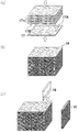
- the plurality of primary sheets 17 obtained in the primary sheet preparation step are laminated so that the orientation directions of the anisotropic fillers are the same (see FIGS. 3A and 3B). That is, one direction along the major axis direction Y and each other direction along the horizontal axis direction X of the scaly filler 12 are laminated so as to coincide with each other among the plurality of primary sheets 17. Then, the plurality of laminated primary sheets 17 are adhered to each other and integrated to obtain a laminated block 18.
- the resin of the laminated primary sheets 17 is a thermoplastic resin
- the polymer matrix 11 in the primary sheets 17 may be melt-fixed to form a laminated block 18 by press molding.
- a known adhesive or the like may be arranged between the primary sheets 17 and 17 to bond the primary sheets 17 and 17.
- a known adhesive or the like may be arranged between the primary sheets 17 and 17 to bond the primary sheets 17 and 17.
- a known adhesive or the like may be arranged between the primary sheets 17 and 17 to bond the primary sheets 17 and 17.
- the polymer matrix is a silicone resin or the like
- at least one surface of the obtained primary sheet 17 is irradiated with VUV to activate at least one surface, and by that surface, 1
- the next sheets 17 and 17 may be adhered to each other.
- the VUV is a vacuum ultraviolet ray, and means an ultraviolet ray having a wavelength of 10 to 200 nm.
- Examples of the VUV light source include an excimer Xe lamp and an excimer ArF lamp.
- the primary sheet 17 contains, for example, a silicone resin (organopolysiloxane) as described above
- a silicone resin organopolysiloxane
- the primary sheet 17 is overlapped with the other primary sheet 17 so that one of the activated surfaces becomes a superposed surface, so that the space between the primary sheets 17 and 17 is firmly formed. It will be glued.
- the silicone resin when VUV is irradiated, the C—Si bond of the organopolysiloxane changes to the Si—O bond such as Si—OH, and the Si—O bond causes the silicone resin. It is presumed that the primary sheets 17 and 17 are firmly adhered to each other.
- the primary sheet 17 and the primary sheet (unit layers 14, 14) are adhered by forming a bond between the molecules of the organopolysiloxane. Further, by adhering the primary sheets 17 and 17 to each other by VUV irradiation, the flexibility in the direction perpendicular to the laminating direction is not significantly impaired. Therefore, it becomes easy to adjust the above-mentioned compression ratio within a predetermined range.
- the VUV irradiation conditions are not particularly limited as long as the surface of the primary sheet 17 can be activated, but for example, the integrated light amount is 5 to 100 mJ / cm 2 , preferably the integrated light amount is 10 to 50 mJ / cm 2. Irradiation with VUV is recommended.
- each of the primary sheets 17 may be subjected to VUV irradiation in advance on any one of the overlapping surfaces that are in contact with each other. Since one surface is irradiated with VUV, the adjacent primary sheets 17 and 17 are adhered to each other by the activated one surface. Further, from the viewpoint of further improving the adhesiveness, it is preferable that both the overlapping surfaces are irradiated with VUV. That is, as shown in FIG. 3A, it is preferable that one surface 17A of the primary sheet 17 irradiated with VUV is overlapped so as to be in contact with the other primary sheet 17, but at this time, one of them may be overlapped. It is preferable that the other surface 17B of the other primary sheet 17 in contact with the surface 17A is also VUV-irradiated.
- the primary sheets 17 can be bonded by simply stacking them as described above, but in order to bond them more firmly, the primary sheets 17 may be pressurized in the stacking direction.
- the pressurization is preferably performed at a pressure such that the primary sheet 17 is not significantly deformed, and can be pressurized by using, for example, a roller or a press.
- the pressure is preferably 0.3 to 3 kgf / 50 mm.
- the laminated primary sheet 17 may be appropriately heated, for example, when pressurizing, but the primary sheet 17 activated by VUV irradiation can be adhered without heating, so that the laminated primary sheet 17 can be adhered without heating.
- the sheet 17 is preferably not heated. Therefore, the temperature at the time of pressing is, for example, 0 to 50 ° C., preferably about 10 to 40 ° C.
- the laminated block 18 is cut along the laminating direction (third direction) of the primary sheet 17 by the cutting tool 19 to obtain the heat conductive sheet 10.
- the laminated block 18 may be cut in a direction orthogonal to one direction (first direction) along the major axis direction of the scaly filler 12.
- a double-edged blade such as a razor blade or a cutter knife, a single-edged blade, a round blade, a wire blade, a saw blade, or the like can be used.
- the laminated block 18 is cut by using a cutting tool 19, for example, by a method such as pushing, shearing, rotating, or sliding.
- the direction along the major axis direction Y of the scaly filler 12 was the sheet thickness direction (first direction), but as shown in FIG. 4, the heat conduction in the present embodiment.
- the direction along the major axis direction Y (see FIG. 2) of the scaly filler 12 is one direction (second direction) perpendicular to the thickness direction of the sheet, and is along the horizontal axis direction X. The difference is that the direction is the thickness direction of the sheet (first direction).
- the thermal conductivity is improved not only in the thickness direction but also in one direction along the plane direction perpendicular to the thickness direction.
- the thermal conductivity in one direction (second direction) along the surface direction is the thickness direction (first direction).
- the heat conductive sheet 20 of the present embodiment can be suitably used in applications where high heat conductivity is required along the plane direction.
- the thermal conductivity in the first direction is preferably 2.5 W / (m ⁇ K) or more, more preferably 3 W / (m ⁇ K) or more, still more preferably 4.5 W / (m). ⁇ K) or more, and for example, 50 W / (m ⁇ K) or less.
- the thermal conductivity in the second direction is higher than the thermal conductivity in the first direction, for example, 5 W / (m ⁇ K) or more, preferably 8 W / (m ⁇ K) or more, more preferably 11 W / (m). ⁇ K) or more, and for example, 50 W / (m ⁇ K) or less.
- the thermal conductivity in the third direction is lower than the thermal conductivity in the first and second directions, preferably less than 4.5 W / (m ⁇ K), more preferably 3 W / (m ⁇ K). It is less than K), more preferably less than 2.5 W / (m ⁇ K), and more than, for example, 0.2 W / (m ⁇ K). Further, as described above, the thermal characteristic level in the second direction is preferably 10% or more, but usually exceeds 100%. Further, the weighted average value of the first aspect ratio of the scaly filler 12 and the aspect ratio of the fibrous filler 13 can be said to be the aspect ratio in the second direction / first direction in the present embodiment.
- the aspect ratio in the second direction / first direction in the present embodiment may be 1 or more, preferably 1.5 or more, more preferably 1.7 or more, and further 3 or more. It is preferably 8 or less, more preferably 7 or less, and even more preferably 5 or less.
- the heat conductive sheet 20 in the present embodiment may contain other fillers such as the fibrous filler 13 and the non-anisotropic filler as in the first embodiment.
- the fibrous filler 13 When the fibrous filler 13 is blended, the fibrous filler 13 may be oriented along the second direction in the fiber axial direction.
- the physical characteristics, dimensions, etc. of the sheet thickness, unit layer thickness 14L, heat conductive sheet type E hardness, and compressibility when compressed in the thickness direction at 0.276 MPa are the above-mentioned first items.
- the configurations of the other second embodiments are the same as those of the first embodiment, and detailed description thereof will be omitted.
- the method for manufacturing the heat conductive sheet 20 in the present embodiment is the same as that in the first embodiment, except that in the cutting step, the scaly filler 12 is cut in a direction orthogonal to one direction along the horizontal axis direction. Just do it.
- each unit layer 14 in the heat conductive sheet 20 has substantially the same composition as described above, but the composition of each unit layer 14 is different. They may be different from each other.
- each unit layer 14 does not have to have the same content of the scaly filler 12, or the scaly filler 12 and the fibrous filler 13, and the scaly filler 12 in some of the unit layers 14 does not have to have the same content.
- the content of the fibrous filler 13 may be different from the content of the scaly filler 12 or the fibrous filler 13 in the other unit layer 14.
- the content of the non-anisotropic filler in some unit layers 14 may be different from the content of the non-anisotropic filler in the other unit layers 14. Further, at least one of the scaly filler 12, the fibrous filler 13, and the non-anisotropic filler in some unit layers 14 may be different from these types in other unit layers 14. Good. Further, in the plurality of unit layers 14, not all unit layers 14 need to contain the scaly filler 12, and some unit layers 14 may contain the scaly filler 12, for example, a plurality of unit layers 14. At least one unit layer 14 of the unit layers 14 may contain a scaly filler 12.
- the scaly filler 12 along one direction in the first and second directions is contained in all the regions of the heat conductive sheet 20, and the heat conductive sheet 20 does not need to be contained. It is preferable that a scaly filler 12 along either the first or second direction is contained in a part.
- a part of the plurality of unit layers 14 may contain the fibrous filler 13, and the other may not contain the fibrous filler 13. Further, it is not necessary that a part of the plurality of unit layers 14 contains a non-anisotropic filler and the other does not contain a non-anisotropic filler.
- the thermal conductivity of some of the unit layers 14 can be changed to other unit layers. It may be made higher than the thermal conductivity of 14. In such a case, the unit layer 14 having a high thermal conductivity and the unit layer 14 having a low thermal conductivity may be arranged alternately, but it is not necessary to arrange them alternately.
- the conductivity of some unit layers 14 may be lower than the conductivity of other unit layers 14.
- the unit layer having high conductivity and the unit layer 14 having low conductivity may be arranged alternately, but it is not necessary to arrange them alternately.
- some unit layers 14 having a low conductivity prevent the conductivity along the third direction (see FIG. 1). Therefore, even in the entire thermal conductive sheet 20, the conductivity in the third direction becomes low, and it becomes easy to secure the insulating property.
- the unit layer 14 having a low conductivity may not contain the conductive heat conductive filler but may contain the insulating heat conductive filler. preferable.
- a part of the plurality of unit layers 14 may be a unit layer 14 having a relatively high thermal conductivity, and the other part may be a unit layer 14 having a light transmittance.
- the unit layer 14 having thermal conductivity is a layer containing a thermally conductive filler such as a thermally conductive filler and a scaly filler 12 as described above.
- the light-transmitting unit layer 14 may be, for example, a layer that does not contain a heat conductive filler. According to such a configuration, the entire heat conductive sheet 20 also has constant heat conductivity and light transmission along the thickness direction.
- the unit layer 14 having thermal conductivity and the unit layer 14 having light transmittance may be arranged alternately, but it is not necessary to arrange them alternately.
- orientation directions of the scaly filler 12 of each unit layer 14 in the major axis direction Y need not all be aligned in the same direction (that is, one direction in the first and second directions). That is, in the present invention, in at least a part of the unit layers 14, the orientation direction in the major axis direction Y is either the first direction or the second direction, and the orientation direction in the horizontal axis direction X is the first direction. Or it may be the other in the second direction.
- the first directions in each unit layer 14 may be sequentially laminated so as to be 90 ° to each other or changed at an arbitrary angle.
- the composition other than the heat conductive filler may be changed for each unit layer 14.
- the type of the polymer matrix 11 of some unit layers 14 may be changed from the type of the polymer matrix 11 of another unit layer 14.
- the presence / absence of the additive component in some of the unit layers 14, the type and amount of the additive components, and the like may be different from those of the other unit layers 14.
- the hardness of some unit layers 14 is hardened. The hardness (type E hardness or type OO hardness) may be different from the hardness of the other unit layer 14.
- the evaluation method in this example is as follows. [Measurement of viscosity of liquid composition (mixture)] The viscosities of the liquid compositions of each example were measured with a viscometer (rotational viscometer DV-E manufactured by BROOKFIELD) using a rotor of the spindle SC4-14 at a rotation speed of 1 rpm and a measurement temperature of 25 ° C. The results are shown in Table 1.
- the thermal conductivity in the thickness direction (first direction) of the produced thermally conductive sheet was measured by a method according to ASTM D5470-06.
- the thermal conductivity in the second direction and the third direction was also measured by a method according to ASTM D5470-06.
- the results are shown in Table 1.
- the thermal conductivity in the second direction is a thermal conductivity measured by cutting a test piece (thickness 2 mm) obtained by cutting a laminated block of each example described later so that the second direction is the thickness direction.
- the thermal conductivity in the third direction is the thermal conductivity measured by measuring the primary sheet (thickness 2 mm) of each example.
- the level of thermal properties in the second direction is shown as a percentage.
- Type E hardness The Type E hardness was measured according to the regulations of ASTM D2240-05 as a 10 mm test piece by stacking five heat conductive sheets and primary sheets obtained in each Example and Comparative Example. The results are shown in Table 1.
- Example 1 As a curable silicone composition, an alkenyl group-containing organopolysiloxane (main agent) and a hydrogen organopolysiloxane (curing agent) (total 100 parts by mass, volume filling rate 38% by volume), and boron nitride powder as a scaly filler.
- the liquid composition was unidirectionally coated on a base film made of polyethylene terephthalate (PET) at 25 ° C. using a bar coater as a coating applicator.
- the scaly filler was oriented so that the major axis direction X was along the coating direction, the horizontal axis direction X was one direction in the sheet surface direction, and the direction was perpendicular to the coating direction.
- the applied liquid composition was heated at 120 ° C. for 0.5 hours to cure the liquid composition, thereby obtaining a primary sheet having a thickness of 2 mm.
- VUV irradiator (trade name: Excimer MINI, manufactured by Hamamatsu Photonics Co., Ltd.) was used on both sides of each of the obtained primary sheets, and the integrated light amount was 20 mJ / on the surface of the primary sheet in the air at room temperature (25 ° C.). VUV was irradiated under the condition of cm 2. Next, 100 VUV-irradiated primary sheets were laminated and pressed by a roller at a pressure of 1.6 kgf / 50 mm in an environment of 25 ° C. to obtain a laminated block.
- the obtained laminated block is sliced by a cutter blade parallel to the laminating direction and perpendicular to the direction along the long axis direction of the scaly filler, and each unit layer has a thickness of 2 mm and a sheet thickness of 2 mm.
- the heat conductive sheet of was obtained.
- the scaly filler has a major axis direction along the thickness direction (first direction) and a horizontal axis direction perpendicular to the first direction in the sheet surface direction (second direction). It was oriented along. The same was true for each of the following examples.
- the volume filling rate of the silicone resin is 38% by volume
- the volume filling rate of the scaly filler is 23% by volume
- the volume filling rate of the non-isometric filler is 39% by volume
- the viscosity of the liquid composition at 25 ° C. is 600 Pa. ⁇ It was s.
- the volume filling rate of the silicone resin and each filler was the same as in Example 2, and the viscosity of the liquid composition at 25 ° C. was 750 Pa ⁇ s.
- Example 5 In the preparation of the liquid composition, graphitized carbon fibers (average fiber length 100 ⁇ m, aspect ratio 10, thermal conductivity 500 W / (m ⁇ K)) are further blended as the fibrous filler, and the number of parts of each filler is blended. It was carried out in the same manner as in Example 4 except that the changes were made as described in Table 1. The fibrous filler was oriented so that the fiber axis direction was along the thickness direction (first direction), and the same was true in the following Examples and Comparative Examples.
- the volume filling rate of the silicone resin is 38% by volume
- the volume filling rate of the scaly filler is 9% by volume
- the volume filling rate of the fibrous filler is 14% by volume
- the volume filling rate of the non-anisometric filler is 39 volumes. %
- the viscosity of the liquid composition at 25 ° C. was 750 Pa ⁇ s.
- Example 6 In the preparation of the liquid composition, the same procedure as in Example 5 was carried out except that the number of copies of each filler was changed as shown in Table 1.
- the volume filling rate of the silicone resin is 38% by volume
- the volume filling rate of the scaly filler is 14% by volume
- the volume filling rate of the fibrous filler is 9% by volume
- the volume filling rate of the non-anisometric filler is 39 volumes. %
- the viscosity of the liquid composition at 25 ° C. was 540 Pa ⁇ s.
- Example 7 In the preparation of the liquid composition, the same procedure as in Example 4 was carried out except that the number of copies of each filler was changed as shown in Table 1.
- the volume filling rate of the silicone resin is 38% by volume
- the volume filling rate of the scaly filler is 22% by volume
- the volume filling rate of the non-isometric filler is 40% by volume
- the viscosity of the liquid composition at 25 ° C. is 960 Pa. ⁇ It was s.
- Example 1 In the preparation of the liquid composition, the same procedure as in Example 1 was carried out except that the scaly filler was not used and the number of copies of each filler was changed as shown in Table 1.
- the volume filling rate of the silicone resin is 37% by volume
- the volume filling rate of the fibrous filler is 20% by volume
- the volume filling rate of the non-anisometric filler is 43% by volume
- the viscosity of the liquid composition at 25 ° C. is 360 Pa. It was s.
- Example 2 In the preparation of the liquid composition, the same procedure as in Example 1 was carried out except that the scaly filler was not used and the number of copies of each filler was changed as shown in Table 1.
- the volume filling rate of the silicone resin is 38% by volume
- the volume filling rate of the fibrous filler is 22% by volume
- the volume filling rate of the non-anisometric filler is 40% by volume
- the viscosity of the liquid composition at 25 ° C. is 450 Pa. It was s.
- the scaly filler is contained, and the scaly filler is arranged along the major axis direction Y in the first direction and the horizontal axis direction X along the second direction.
- the thermal conductivity was improved not only in the thickness direction (first direction) but also in one direction (second direction) along the surface direction. Therefore, the thermal conductivity in one direction along the thickness direction and the surface direction is improved, and the thermal resistance in these directions is lowered.
- the thermal conductive sheet of each comparative example did not contain a scaly filler in which the major axis direction Y was oriented in the first direction and the horizontal axis direction X was oriented in the second direction. , The thermal conductivity in both the thickness direction and the one direction along the plane direction was not improved, so that the thermal resistance values in both the thickness direction and the one direction along the plane direction could not be lowered.
Landscapes
- Chemical & Material Sciences (AREA)
- Engineering & Computer Science (AREA)
- Composite Materials (AREA)
- Mechanical Engineering (AREA)
- Materials Engineering (AREA)
- Chemical Kinetics & Catalysis (AREA)
- Organic Chemistry (AREA)
- Manufacturing & Machinery (AREA)
- Thermal Sciences (AREA)
- Combustion & Propulsion (AREA)
- Physics & Mathematics (AREA)
- Health & Medical Sciences (AREA)
- Medicinal Chemistry (AREA)
- Polymers & Plastics (AREA)
- Cooling Or The Like Of Semiconductors Or Solid State Devices (AREA)
- Compositions Of Macromolecular Compounds (AREA)
- Cooling Or The Like Of Electrical Apparatus (AREA)
- Manufacture Of Macromolecular Shaped Articles (AREA)
- Moulding By Coating Moulds (AREA)
- Ceramic Engineering (AREA)
Priority Applications (7)
| Application Number | Priority Date | Filing Date | Title |
|---|---|---|---|
| KR1020227013284A KR102452165B1 (ko) | 2019-11-01 | 2020-10-26 | 열전도성 시트 및 그 제조 방법 |
| KR1020227030763A KR20220129092A (ko) | 2019-11-01 | 2020-10-26 | 열전도성 시트 및 그 제조 방법 |
| CN202310426568.9A CN116355425B (zh) | 2019-11-01 | 2020-10-26 | 导热片及其制造方法 |
| CN202080072965.5A CN114555714B (zh) | 2019-11-01 | 2020-10-26 | 导热片及其制造方法 |
| US17/770,539 US11618247B2 (en) | 2019-11-01 | 2020-10-26 | Thermally conductive sheet and production method for same |
| DE112020005404.7T DE112020005404T5 (de) | 2019-11-01 | 2020-10-26 | Wärmeleitende folie und herstellungsverfahren für dieselbe |
| JP2021507107A JP6892725B1 (ja) | 2019-11-01 | 2020-10-26 | 熱伝導性シート及びその製造方法 |
Applications Claiming Priority (2)
| Application Number | Priority Date | Filing Date | Title |
|---|---|---|---|
| JP2019200095 | 2019-11-01 | ||
| JP2019-200095 | 2019-11-01 |
Publications (1)
| Publication Number | Publication Date |
|---|---|
| WO2021085383A1 true WO2021085383A1 (ja) | 2021-05-06 |
Family
ID=75715943
Family Applications (1)
| Application Number | Title | Priority Date | Filing Date |
|---|---|---|---|
| PCT/JP2020/040121 Ceased WO2021085383A1 (ja) | 2019-11-01 | 2020-10-26 | 熱伝導性シート及びその製造方法 |
Country Status (7)
| Country | Link |
|---|---|
| US (1) | US11618247B2 (https=) |
| JP (3) | JP6892725B1 (https=) |
| KR (2) | KR102452165B1 (https=) |
| CN (2) | CN116355425B (https=) |
| DE (1) | DE112020005404T5 (https=) |
| TW (1) | TWI901607B (https=) |
| WO (1) | WO2021085383A1 (https=) |
Cited By (1)
| Publication number | Priority date | Publication date | Assignee | Title |
|---|---|---|---|---|
| JP7582540B1 (ja) | 2024-03-28 | 2024-11-13 | 日本ゼオン株式会社 | 熱伝導シート及びその製造方法 |
Families Citing this family (13)
| Publication number | Priority date | Publication date | Assignee | Title |
|---|---|---|---|---|
| WO2019244890A1 (ja) | 2018-06-22 | 2019-12-26 | 積水ポリマテック株式会社 | 熱伝導性シート |
| JP7618954B2 (ja) * | 2018-09-26 | 2025-01-22 | 積水ポリマテック株式会社 | 熱伝導性シート |
| JP7542317B2 (ja) * | 2020-02-06 | 2024-08-30 | 積水化学工業株式会社 | 熱伝導性樹脂シート |
| CN117624899A (zh) * | 2020-05-15 | 2024-03-01 | 迪睿合株式会社 | 导热性片和导热性片的制造方法 |
| JP6980868B1 (ja) * | 2020-08-25 | 2021-12-15 | デクセリアルズ株式会社 | 熱伝導性シート及び熱伝導性シートの製造方法 |
| JP6999003B1 (ja) | 2020-09-09 | 2022-01-18 | デクセリアルズ株式会社 | 熱伝導性シート及び熱伝導性シートの製造方法 |
| JP7811376B2 (ja) * | 2021-10-08 | 2026-02-05 | 株式会社昭和丸筒 | 電子回路基板及び電子回路基板の製造方法 |
| WO2024018635A1 (ja) * | 2022-07-22 | 2024-01-25 | 株式会社レゾナック | 熱伝導シート、放熱装置及び熱伝導シートの製造方法 |
| US11615999B1 (en) * | 2022-07-22 | 2023-03-28 | GuangDong Suqun New Material Co., Ltd | Oriented heat conducting sheet and preparation method thereof, and semiconductor heat dissipating device |
| WO2024090364A1 (ja) * | 2022-10-28 | 2024-05-02 | 帝人株式会社 | 積層体及びその製造方法 |
| JP7793114B1 (ja) * | 2024-03-28 | 2025-12-26 | 積水化学工業株式会社 | 熱伝導性シート |
| KR102851466B1 (ko) * | 2024-08-20 | 2025-08-29 | 조인셋 주식회사 | 이방성 열전부재 및 그 제조방법 |
| WO2026043264A1 (ko) * | 2024-08-20 | 2026-02-26 | 조인셋 주식회사 | 열전부재 및 그 제조방법 |
Citations (5)
| Publication number | Priority date | Publication date | Assignee | Title |
|---|---|---|---|---|
| JP2009094110A (ja) * | 2007-10-03 | 2009-04-30 | Denki Kagaku Kogyo Kk | 放熱部材、及びそのシート、およびその製造方法 |
| JP2014148094A (ja) * | 2013-02-01 | 2014-08-21 | Sumitomo Bakelite Co Ltd | 熱伝導シートおよび熱伝導シートの製造方法 |
| WO2017179318A1 (ja) * | 2016-04-11 | 2017-10-19 | ポリマテック・ジャパン株式会社 | 熱伝導性シート |
| JP2019026884A (ja) * | 2017-07-28 | 2019-02-21 | 昭和電工株式会社 | 金属−炭素粒子複合材 |
| WO2019160004A1 (ja) * | 2018-02-14 | 2019-08-22 | 積水ポリマテック株式会社 | 熱伝導性シート |
Family Cites Families (32)
| Publication number | Priority date | Publication date | Assignee | Title |
|---|---|---|---|---|
| JPH09283955A (ja) | 1996-04-10 | 1997-10-31 | Matsushita Electric Works Ltd | 放熱シート |
| JP2001110961A (ja) | 1999-10-08 | 2001-04-20 | Fujikura Rubber Ltd | 放熱シート |
| JP2002026202A (ja) | 2000-06-29 | 2002-01-25 | Three M Innovative Properties Co | 熱伝導性シート及びその製造方法 |
| JP2002121393A (ja) | 2000-10-12 | 2002-04-23 | Sekisui Chem Co Ltd | 熱伝導性樹脂組成物及び熱伝導性シート |
| JP2004051852A (ja) | 2002-07-22 | 2004-02-19 | Polymatech Co Ltd | 熱伝導性高分子成形体及びその製造方法 |
| JP4629475B2 (ja) | 2005-03-30 | 2011-02-09 | 株式会社カネカ | 放熱シート用組成物およびそれを硬化させてなる放熱シート |
| JP2007012913A (ja) | 2005-06-30 | 2007-01-18 | Polymatech Co Ltd | 放熱シート及び放熱構造 |
| CN102433105B (zh) | 2006-11-01 | 2014-07-30 | 日立化成株式会社 | 导热片、其制造方法以及使用了导热片的散热装置 |
| JP2009004536A (ja) * | 2007-06-21 | 2009-01-08 | Mitsubishi Electric Corp | 熱伝導性樹脂シート及びこれを用いたパワーモジュール |
| JP5185582B2 (ja) * | 2007-09-11 | 2013-04-17 | 日本バルカー工業株式会社 | 熱伝導性シート |
| JP5274007B2 (ja) * | 2007-12-27 | 2013-08-28 | 三菱電機株式会社 | 熱伝導性樹脂シートおよびこれを用いたパワーモジュール |
| JP2010114421A (ja) * | 2008-10-08 | 2010-05-20 | Hitachi Chem Co Ltd | 熱伝導シート、及びその熱伝導シートの製造方法 |
| CN104086929A (zh) | 2008-10-21 | 2014-10-08 | 日立化成工业株式会社 | 导热片材、其制造方法以及使用了该导热片材的散热装置 |
| JP2011184663A (ja) | 2010-03-11 | 2011-09-22 | Hitachi Chem Co Ltd | 熱伝導シート、その製造方法及びこれを用いた放熱装置 |
| JP5454300B2 (ja) | 2010-03-30 | 2014-03-26 | 日立化成株式会社 | 熱伝導シート、その製造方法及びこれを用いた放熱装置 |
| JP2013062379A (ja) * | 2011-09-13 | 2013-04-04 | Nitto Denko Corp | 熱伝導性シートおよびその製造方法 |
| JP5443657B2 (ja) | 2011-12-27 | 2014-03-19 | パナソニック株式会社 | シートの異方性熱伝導組成物の成形品 |
| JP2014014809A (ja) | 2012-07-11 | 2014-01-30 | Fujifilm Corp | 二酸化炭素分離用複合体の製造方法、二酸化炭素分離用複合体、二酸化炭素分離モジュール、二酸化炭素分離装置、及び二酸化炭素分離システム |
| JP5953160B2 (ja) | 2012-07-27 | 2016-07-20 | ポリマテック・ジャパン株式会社 | 熱伝導性成形体の製造方法 |
| JP6094119B2 (ja) | 2012-09-26 | 2017-03-15 | 住友ベークライト株式会社 | 熱伝導シートの製造方法 |
| JP2014150161A (ja) | 2013-02-01 | 2014-08-21 | Sumitomo Bakelite Co Ltd | 熱伝導シートの製造方法および熱伝導シート |
| JP6219624B2 (ja) * | 2013-07-04 | 2017-10-25 | デクセリアルズ株式会社 | 熱伝導シートの製造方法、熱伝導シートの製造装置、樹脂成型体の切断方法 |
| JP5798210B2 (ja) | 2013-07-10 | 2015-10-21 | デクセリアルズ株式会社 | 熱伝導性シート |
| JP6071935B2 (ja) | 2013-09-06 | 2017-02-01 | バンドー化学株式会社 | 樹脂成形品の製造方法 |
| CN109196052B (zh) * | 2016-05-31 | 2021-05-07 | 积水保力马科技株式会社 | 导热部件、导热组合物及导热组合物的制造方法 |
| JP6750019B2 (ja) * | 2016-08-08 | 2020-09-02 | 積水化学工業株式会社 | 熱伝導シート及びその製造方法 |
| JPWO2018123012A1 (ja) * | 2016-12-28 | 2019-10-31 | 日立化成株式会社 | 熱伝導シート、熱伝導シートの製造方法及び放熱装置 |
| JPWO2018180997A1 (ja) * | 2017-03-31 | 2019-04-11 | バンドー化学株式会社 | 熱伝導性シート |
| JP7087372B2 (ja) | 2017-12-19 | 2022-06-21 | 日本ゼオン株式会社 | 熱伝導シート及びその製造方法 |
| JP7467024B2 (ja) | 2017-12-25 | 2024-04-15 | 日本ゼオン株式会社 | 熱伝導シート |
| WO2019146633A1 (ja) * | 2018-01-26 | 2019-08-01 | 東レ株式会社 | 繊維強化熱可塑性樹脂成形品および繊維強化熱可塑性樹脂成形材料 |
| JP7650071B2 (ja) | 2019-09-30 | 2025-03-24 | 積水ポリマテック株式会社 | 熱伝導性シート及びその製造方法 |
-
2020
- 2020-10-26 JP JP2021507107A patent/JP6892725B1/ja active Active
- 2020-10-26 CN CN202310426568.9A patent/CN116355425B/zh active Active
- 2020-10-26 US US17/770,539 patent/US11618247B2/en active Active
- 2020-10-26 CN CN202080072965.5A patent/CN114555714B/zh active Active
- 2020-10-26 KR KR1020227013284A patent/KR102452165B1/ko active Active
- 2020-10-26 DE DE112020005404.7T patent/DE112020005404T5/de active Pending
- 2020-10-26 KR KR1020227030763A patent/KR20220129092A/ko not_active Withdrawn
- 2020-10-26 WO PCT/JP2020/040121 patent/WO2021085383A1/ja not_active Ceased
- 2020-10-28 TW TW109137460A patent/TWI901607B/zh active
-
2021
- 2021-05-21 JP JP2021086144A patent/JP7611574B2/ja active Active
-
2024
- 2024-12-17 JP JP2024220885A patent/JP7764001B2/ja active Active
Patent Citations (5)
| Publication number | Priority date | Publication date | Assignee | Title |
|---|---|---|---|---|
| JP2009094110A (ja) * | 2007-10-03 | 2009-04-30 | Denki Kagaku Kogyo Kk | 放熱部材、及びそのシート、およびその製造方法 |
| JP2014148094A (ja) * | 2013-02-01 | 2014-08-21 | Sumitomo Bakelite Co Ltd | 熱伝導シートおよび熱伝導シートの製造方法 |
| WO2017179318A1 (ja) * | 2016-04-11 | 2017-10-19 | ポリマテック・ジャパン株式会社 | 熱伝導性シート |
| JP2019026884A (ja) * | 2017-07-28 | 2019-02-21 | 昭和電工株式会社 | 金属−炭素粒子複合材 |
| WO2019160004A1 (ja) * | 2018-02-14 | 2019-08-22 | 積水ポリマテック株式会社 | 熱伝導性シート |
Cited By (2)
| Publication number | Priority date | Publication date | Assignee | Title |
|---|---|---|---|---|
| JP7582540B1 (ja) | 2024-03-28 | 2024-11-13 | 日本ゼオン株式会社 | 熱伝導シート及びその製造方法 |
| JP2025152187A (ja) * | 2024-03-28 | 2025-10-09 | 日本ゼオン株式会社 | 熱伝導シート及びその製造方法 |
Also Published As
| Publication number | Publication date |
|---|---|
| JP6892725B1 (ja) | 2021-06-23 |
| CN114555714A (zh) | 2022-05-27 |
| KR20220054713A (ko) | 2022-05-03 |
| JP7611574B2 (ja) | 2025-01-10 |
| CN114555714B (zh) | 2023-05-09 |
| KR20220129092A (ko) | 2022-09-22 |
| US20220347996A1 (en) | 2022-11-03 |
| JP2021145134A (ja) | 2021-09-24 |
| CN116355425B (zh) | 2024-10-29 |
| DE112020005404T5 (de) | 2022-08-18 |
| JP7764001B2 (ja) | 2025-11-05 |
| JPWO2021085383A1 (ja) | 2021-11-25 |
| US11618247B2 (en) | 2023-04-04 |
| KR102452165B1 (ko) | 2022-10-11 |
| TWI901607B (zh) | 2025-10-21 |
| TW202124585A (zh) | 2021-07-01 |
| CN116355425A (zh) | 2023-06-30 |
| JP2025038119A (ja) | 2025-03-18 |
Similar Documents
| Publication | Publication Date | Title |
|---|---|---|
| JP6892725B1 (ja) | 熱伝導性シート及びその製造方法 | |
| JP6844806B2 (ja) | 熱伝導性シート及びその製造方法 | |
| JP7650071B2 (ja) | 熱伝導性シート及びその製造方法 | |
| JP6978148B1 (ja) | 熱伝導性シート及びその製造方法 | |
| JP7793114B1 (ja) | 熱伝導性シート | |
| JP7248222B2 (ja) | 熱伝導性部材の製造方法、及びディスペンサ装置 | |
| TW202606877A (zh) | 導熱性片 |
Legal Events
| Date | Code | Title | Description |
|---|---|---|---|
| ENP | Entry into the national phase |
Ref document number: 2021507107 Country of ref document: JP Kind code of ref document: A |
|
| 121 | Ep: the epo has been informed by wipo that ep was designated in this application |
Ref document number: 20881202 Country of ref document: EP Kind code of ref document: A1 |
|
| ENP | Entry into the national phase |
Ref document number: 20227013284 Country of ref document: KR Kind code of ref document: A |
|
| 122 | Ep: pct application non-entry in european phase |
Ref document number: 20881202 Country of ref document: EP Kind code of ref document: A1 |