WO2021065421A1 - 通路開閉装置 - Google Patents
通路開閉装置 Download PDFInfo
- Publication number
- WO2021065421A1 WO2021065421A1 PCT/JP2020/034497 JP2020034497W WO2021065421A1 WO 2021065421 A1 WO2021065421 A1 WO 2021065421A1 JP 2020034497 W JP2020034497 W JP 2020034497W WO 2021065421 A1 WO2021065421 A1 WO 2021065421A1
- Authority
- WO
- WIPO (PCT)
- Prior art keywords
- door
- air
- opening
- cold air
- flow path
- Prior art date
- Legal status (The legal status is an assumption and is not a legal conclusion. Google has not performed a legal analysis and makes no representation as to the accuracy of the status listed.)
- Ceased
Links
Images


Classifications
-
- B—PERFORMING OPERATIONS; TRANSPORTING
- B60—VEHICLES IN GENERAL
- B60H—ARRANGEMENTS OF HEATING, COOLING, VENTILATING OR OTHER AIR-TREATING DEVICES SPECIALLY ADAPTED FOR PASSENGER OR GOODS SPACES OF VEHICLES
- B60H1/00—Heating, cooling or ventilating devices
- B60H1/00642—Control systems or circuits; Control members or indication devices for heating, cooling or ventilating devices
- B60H1/00664—Construction or arrangement of damper doors
- B60H1/00692—Damper doors moved by translation, e.g. curtain doors
-
- B—PERFORMING OPERATIONS; TRANSPORTING
- B60—VEHICLES IN GENERAL
- B60H—ARRANGEMENTS OF HEATING, COOLING, VENTILATING OR OTHER AIR-TREATING DEVICES SPECIALLY ADAPTED FOR PASSENGER OR GOODS SPACES OF VEHICLES
- B60H1/00—Heating, cooling or ventilating devices
- B60H1/00507—Details, e.g. mounting arrangements, desaeration devices
- B60H1/00514—Details of air conditioning housings
-
- B—PERFORMING OPERATIONS; TRANSPORTING
- B60—VEHICLES IN GENERAL
- B60H—ARRANGEMENTS OF HEATING, COOLING, VENTILATING OR OTHER AIR-TREATING DEVICES SPECIALLY ADAPTED FOR PASSENGER OR GOODS SPACES OF VEHICLES
- B60H1/00—Heating, cooling or ventilating devices
- B60H1/00642—Control systems or circuits; Control members or indication devices for heating, cooling or ventilating devices
- B60H1/00664—Construction or arrangement of damper doors
-
- B—PERFORMING OPERATIONS; TRANSPORTING
- B60—VEHICLES IN GENERAL
- B60H—ARRANGEMENTS OF HEATING, COOLING, VENTILATING OR OTHER AIR-TREATING DEVICES SPECIALLY ADAPTED FOR PASSENGER OR GOODS SPACES OF VEHICLES
- B60H1/00—Heating, cooling or ventilating devices
- B60H1/02—Heating, cooling or ventilating devices the heat being derived from the propulsion plant
- B60H1/04—Heating, cooling or ventilating devices the heat being derived from the propulsion plant from cooling liquid of the plant
- B60H1/08—Heating, cooling or ventilating devices the heat being derived from the propulsion plant from cooling liquid of the plant from other radiator than main radiator
- B60H1/10—Heating, cooling or ventilating devices the heat being derived from the propulsion plant from cooling liquid of the plant from other radiator than main radiator the other radiator being situated in a duct capable of being connected to atmosphere outside vehicle
- B60H1/12—Heating, cooling or ventilating devices the heat being derived from the propulsion plant from cooling liquid of the plant from other radiator than main radiator the other radiator being situated in a duct capable of being connected to atmosphere outside vehicle using an air blower
-
- F—MECHANICAL ENGINEERING; LIGHTING; HEATING; WEAPONS; BLASTING
- F24—HEATING; RANGES; VENTILATING
- F24F—AIR-CONDITIONING; AIR-HUMIDIFICATION; VENTILATION; USE OF AIR CURRENTS FOR SCREENING
- F24F13/00—Details common to, or for air-conditioning, air-humidification, ventilation or use of air currents for screening
- F24F13/24—Means for preventing or suppressing noise
-
- B—PERFORMING OPERATIONS; TRANSPORTING
- B60—VEHICLES IN GENERAL
- B60H—ARRANGEMENTS OF HEATING, COOLING, VENTILATING OR OTHER AIR-TREATING DEVICES SPECIALLY ADAPTED FOR PASSENGER OR GOODS SPACES OF VEHICLES
- B60H1/00—Heating, cooling or ventilating devices
- B60H1/00007—Combined heating, ventilating, or cooling devices
- B60H1/00021—Air flow details of HVAC devices
- B60H2001/00078—Assembling, manufacturing or layout details
- B60H2001/00092—Assembling, manufacturing or layout details of air deflecting or air directing means inside the device
-
- B—PERFORMING OPERATIONS; TRANSPORTING
- B60—VEHICLES IN GENERAL
- B60H—ARRANGEMENTS OF HEATING, COOLING, VENTILATING OR OTHER AIR-TREATING DEVICES SPECIALLY ADAPTED FOR PASSENGER OR GOODS SPACES OF VEHICLES
- B60H1/00—Heating, cooling or ventilating devices
- B60H1/00507—Details, e.g. mounting arrangements, desaeration devices
- B60H2001/006—Noise reduction
-
- B—PERFORMING OPERATIONS; TRANSPORTING
- B60—VEHICLES IN GENERAL
- B60H—ARRANGEMENTS OF HEATING, COOLING, VENTILATING OR OTHER AIR-TREATING DEVICES SPECIALLY ADAPTED FOR PASSENGER OR GOODS SPACES OF VEHICLES
- B60H1/00—Heating, cooling or ventilating devices
- B60H1/00642—Control systems or circuits; Control members or indication devices for heating, cooling or ventilating devices
- B60H1/00664—Construction or arrangement of damper doors
- B60H2001/00714—Details of seals of damper doors
Definitions
- the present disclosure relates to a passage opening / closing device for opening / closing an air passage.
- a damping mechanism for damping the vibration is provided on the back surface of the sliding door (see, for example, Patent Document 1).
- An object of the present disclosure is to provide a passage opening / closing device capable of suppressing self-excited vibration of a sliding door while suppressing deterioration of manufacturability of the sliding door.
- the passage opening / closing device is A case in which an opening edge forming an opening of an air passage is provided inside, and a case It is equipped with a sliding door that is arranged so that it can be slidably moved inside the case and opens and closes the opening.
- the sliding door constitutes one end of the sliding door in the door moving direction and includes a door end that faces the opening edge when the sliding door is displaced to a closing position that closes the opening.
- the opening edge includes a door facing wall portion that faces the door end when the sliding door is displaced to the closed position and forms a gap flow path extending along the door moving direction with the door end. At the door end and the door facing wall, the distance between the door end and the door facing wall becomes smaller toward the downstream side of the air flow so that the gap flow path becomes a tapered flow path.
- the passage opening / closing device of the present disclosure does not form a spring structure or attach a bristle material or packing to the sliding door as in the conventional case, so that the manufacturability of the sliding door deteriorates. It is possible to suppress the self-excited vibration of the sliding door while suppressing the above.
- FIG. 2 is a sectional view taken along line III-III of FIG. It is a schematic diagram which shows a part of a guide rail. It is an enlarged view of the V part of FIG. It is explanatory drawing for demonstrating the flow of air in an indoor air-conditioning unit. It is explanatory drawing for demonstrating the state of the air mix door when it is displaced to the closed position of a cold air opening. It is explanatory drawing for demonstrating the door structure including the air mix door which is the comparative example of 1st Embodiment.
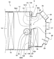
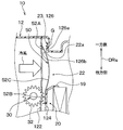
- the indoor air-conditioning unit 10 shown in FIG. 1 is arranged at a substantially central portion in the vehicle width direction of the inside of the instrument panel located at the frontmost portion of the vehicle interior.
- the indoor air-conditioning unit 10 has a case 12 that forms an outer shell thereof and also forms an air passage for blown air that is blown toward the vehicle interior.
- the case 12 is molded of a resin (for example, polypropylene) having a certain degree of elasticity and excellent strength.
- An air inflow space 14 into which the blown air from a blower unit (not shown) flows in is formed on the most upstream side of the air passage formed in the case 12.
- the blower unit is offset from the indoor air conditioning unit 10 on one side (for example, the passenger seat side) in the vehicle width direction.
- the blower unit includes an inside / outside air switching box that switches between the inside / outside air and the outside air, and a blower that blows the air introduced into the inside / outside air switching box.
- the evaporator 16 is arranged on the downstream side of the air flow in the air inflow space 14.
- the evaporator 16 is one of the devices constituting a vapor compression refrigeration cycle (not shown).
- the evaporator 16 is a cooling heat exchanger that cools the air introduced into the air inflow space 14 by evaporating the low-pressure refrigerant in the refrigeration cycle to exert an endothermic action.
- the heater core 18 is arranged on the downstream side of the air flow of the evaporator 16.
- the heater core 18 is a heating heat exchanger that heats the cold air by inflowing high-temperature cooling water that circulates in an engine cooling circuit (not shown) into the inside and exchanging heat between the cooling water and the cold air that has passed through the evaporator 16. ..
- a partition plate portion 19 allows a hot air passage 20 constituting an air passage for flowing cold air to the heater core 18 and a cold air bypassing the heater core 18 to flow.
- the cold air passage 22 constituting the air passage is formed in parallel.
- the hot air passage 20 and the cold air passage 22 are air passages through which air passes.
- a hot air opening 20a serving as an air inlet of the hot air passage 20 and a cold air opening 22a serving as an air inlet of the cold air passage 22 are provided inside the case 12.
- the warm air opening 20a is an opening formed by the hot air opening edge 21 provided inside the case 12.
- the cold air opening 22a is an opening formed by the cold air opening edge 23 provided inside the case 12.
- the hot air opening 20a and the cold air opening 22a form an opening of the air passage.
- an air mix door 50 for adjusting the air volume ratio between the cold air flowing into the hot air passage 20 and the cold air flowing into the cold air passage 22 is arranged between the evaporator 16 and the heater core 18. There is.
- the air mix door 50 constitutes a sliding door that opens and closes the air passage in the passage opening / closing device. That is, the air mix door 50 is composed of a slide door that is slidably arranged inside the case 12 and opens and closes the hot air opening 20a and the cold air opening 22a.
- the sliding door is not a film door that opens and closes by being wound around a drive shaft 30 and moves, but a door that opens and closes by reciprocating while maintaining a predetermined form. Sliding doors are also different from film doors in that they do not have holes for ventilation.
- the air mix door 50 moves upward in the figure as shown by the solid line in the figure, so that the passage opening of the warm air passage 20 increases. That is, when the air mix door 50 is displaced to the position shown by the solid line in the drawing, the opening area of the warm air opening 20a increases.
- the air mix door 50 moves downward in the figure as shown by the broken line in the figure, so that the passage opening of the cold air passage 22 increases. That is, when the air mix door 50 is displaced to the position indicated by the broken line in the drawing, the opening area of the cold air opening 22a increases.
- the indoor air conditioning unit 10 adjusts the drive position of the air mix door 50 to adjust the air volume ratio between the cold air flowing into the heater core 18 and the cold air flowing around the heater core 18, so that the temperature of the air blown into the vehicle interior is adjusted. Is adjusted.
- the air mix door 50 can slide and move inside the case 12 by the rotational force of the pinion 32 connected to the drive shaft 30. The details of the door structure of the air mix door 50 will be described later.
- the case 12 On the most downstream side of the air passage formed in the case 12, a plurality of openings for blowing out temperature-controlled air inside the case 12 into the vehicle interior are formed. Specifically, the case 12 is formed with three openings such as a defroster opening 24, a face opening 26, and a foot opening 28.
- the defroster opening 24 is an opening that blows air toward the inner surface side of the window glass on the front surface of the vehicle.
- the defroster opening 24 is opened and closed by a defroster door 25 provided inside the case 12.
- the defroster door 25 is rotationally driven by a servomotor or the like (not shown).
- the face opening 26 is an opening that blows air toward the upper body side of the occupant in the vehicle interior through a duct (not shown).
- the face opening 26 is opened and closed by a face door 27 provided inside the case 12.
- the face door 27 is rotationally driven by a servomotor or the like (not shown).
- the foot opening 28 is an opening that blows air toward the lower body side of the occupant in the vehicle interior through a duct (not shown).
- the foot opening 28 is opened and closed by a foot door 29 provided inside the case 12.
- the foot door 29 is rotationally driven by a servomotor or the like (not shown).
- FIGS. 2 to 5 the details of the door structure of the air mix door 50 will be described with reference to FIGS. 2 to 5.
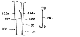
- the direction in which the air mix door 50 moves is shown as the door moving direction DRs
- the direction orthogonal to the door moving direction DRs on the plate surface of the air mix door 50 is shown as the door width direction DRw.
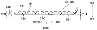
- the air mix door 50 includes a plate-shaped door body 52 and a pair of racks 54 and 55 that mesh with a pinion 32 connected to a drive shaft 30. There is.
- the door body 52 is made of a flexible thin plate member formed of a resin such as polypropylene.
- the door body 52 has a door front portion 521 located on the upstream side (that is, upwind side) of the air flow in the air passage, and a door back portion 522 located on the downstream side (that is, leeward side) of the air flow in the air passage. ing.
- the pair of racks 54 and 55 are formed so as to extend along the door moving direction DRs in the door front portion 521 of the door main body portion 52.
- the pair of racks 54 and 55 project from the door front surface portion 521 of the door body portion 52 toward the windward side.
- the pair of racks 54 and 55 are formed at a portion inside the both ends in the door width direction DRw.
- the pair of racks 54 and 55 are integrally molded with the door body 52. That is, the door body 52 and the pair of racks 54 and 55 are configured as integrally molded products.
- the pinion 32 is connected to the drive shaft 30 as shown in FIG.
- the drive shaft 30 is rotatably supported at both ends by bearing holes formed on the side wall surface of the case 12. Then, one end of the drive shaft 30 is coupled to a door drive device such as a servomotor.
- the door body 52 includes a cold air side end 52A forming one end of the door moving direction DRs, a hot air side end 52B forming the other end of the door moving direction DRs, and a cold air side end 52A. It has a door intermediate portion 52C located between the hot air side end portion 52B and the door intermediate portion 52B.
- the cold air side end 52A is a door end facing the cold air opening edge 23 when the air mix door 50 is displaced to a closing position that closes the cold air opening 22a.
- the cold air side end portion 52A is curved in an arc shape so that one side of the door moving direction DRs protrudes toward the windward side.
- the warm air side end 52B is a door end facing the warm air opening edge 21 when the air mix door 50 is displaced to a closing position that closes the warm air opening 20a.
- the warm air side end 52B is curved in an arc shape so that the other side of the door moving direction DRs protrudes toward the windward side.
- the door intermediate portion 52C covers the cold air opening 22a when the air mix door 50 is displaced to the closing position where the cold air opening 22a is closed, and is displaced to the closing position where the air mix door 50 closes the hot air opening 20a. It is a portion that covers the warm air opening 20a at the time of the displacement.
- the door intermediate portion 52C has a plate thickness Td equivalent to that of the cold air side end portion 52A and the warm air side end portion 52B. As a result, the door intermediate portion 52C has the same rigidity as the cold air side end portion 52A and the hot air side end portion 52B.
- the door main body 52 is a main body central portion 523 sandwiched between the pair of racks 54 and 55 in the door width direction DRw, and a pair of main body side portions 524 located outside the pair of racks 54 and 55 in the door width direction DRw. Has 525.
- the case 12 is formed with a pair of guide rails 122 and 124 that slidably support the door main body 52 at positions corresponding to the pair of main body side portions 524 and 525 of the door main body 52.
- a pair of main body side portions 524 and 525 are interposed between the pair of guide rails 122 and 124.
- the guide rail 122 located on the windward side faces the door front portion 521 of the door body portion 52
- the guide rail 124 located on the leeward side faces the door body portion. It faces the back surface portion 522 of the door 52.
- the pair of guide rails 122 and 124 guide the movement of the air mix door 50 and extend along the door movement direction DRs.
- the pair of guide rails 122 and 124 have rail ends 122a and 124a that guide both ends of the pair of main body side portions 524 and 525 in the door moving direction DRs, and the rail end portions 122a, The 124a also extends along the door moving direction DRs.
- the pair of guide rails 122 and 124 are curved so as to bulge toward the leeward side so that the door main body 52 is supported at three points of the substantially central portion and the substantially both end portions of the door moving direction DRs. .. That is, the pair of guide rails 122 and 124 have a shape curved in an arc shape when viewed from the door width direction DRw. The distance between the pair of guide rails 122 and 124 is substantially constant in the extending direction.
- a pair of main body side portions 524 and 525 of the door main body portion 52 are inserted between the pair of guide rails 122 and 124.
- the door body 52 is flat in a single state, but when both ends thereof are inserted between the pair of guide rails 122 and 124, the door body 52 is elastically deformed along the curved shape of the pair of guide rails 122 and 124. doing.
- the door main body 52 is supported by a pair of guide rails 122 and 124 at three points, a substantially central portion and a substantially both end portions of the door moving direction DRs.
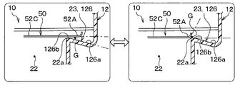
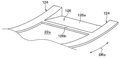
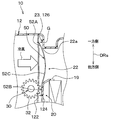
- the case 12 is formed with a cold air seal portion 126 facing the cold air side end portion 52A of the air mix door 50 when the air mix door 50 is displaced to the closed position of the cold air opening 22a. Further, the case 12 is formed with a warm air seal portion 128 facing the warm air side end portion 52B of the air mix door 50 when the air mix door 50 is displaced to the closed position of the warm air opening 20a.
- the cold air seal portion 126 constitutes a door facing wall portion that forms a gap flow path G extending along the door moving direction DRs with the cold air side end portion 52A.
- the distance between the cold air side end portion 52A and the cold air seal portion 126 is on the downstream side of the air flow so that the gap flow path G becomes a tapered flow path. It is configured to become smaller toward.
- the distance between the cold air side end portion 52A and the cold air sealing portion 126 decreases toward the downstream side in the flow direction of the air leaking through the gap flow path G (that is, the leaking air).
- This leaked air is air that leaks from between the door end and the door facing wall toward the passage downstream of the opening when the sliding door is displaced to a position where the opening is closed.
- the leaked air is air that leaks from between the cold air side end portion 52A and the cold air seal portion 126 toward the cold air passage 22 when the air mix door 50 is displaced to the closed position of the cold air opening 22a. ..
- the leaked air is mainly in the door moving direction DRs, unlike the flow direction of the air passing through the cold air opening 22a (that is, the mainstream air) when the air mix door 50 is displaced to the open position of the cold air opening 22a. It flows along.
- the cold air seal portion 126 is provided with an inclined portion 126a that is inclined with respect to the door moving direction DRs so as to move away from the cold air side end portion 52A as the distance from the cold air opening 22a increases.
- the inclined portion 126a is provided at a position facing the cold air side end portion 52A when the air mix door 50 is displaced to a position where the cold air opening 22a is closed.
- the inclined portion 126a is configured such that the inclined angle ⁇ s formed by the inclined surface facing the cold air side end portion 52A and the door moving direction DRs is an acute angle. Further, the inclined portion 126a is inclined with respect to the door moving direction DRs so that the distance from the cold air side end portion 52A becomes continuously large as the distance from the cold air opening 22a increases. In other words, the inclined portion 126a is inclined with respect to the door moving direction DRs so that the passage area of the gap flow path G becomes continuously smaller toward the cold air opening 22a.
- the inclined portion 126a may have at least an inner surface facing the cold air side end portion 52A inclined with respect to the door moving direction DRs. For example, the inclined portion 126a may have an outer surface that does not face the cold air side end portion 52A extending along the door moving direction DRs.
- the portions constituting the pair of main body side portions 524 and 525 are guided by the pair of guide rails 122 and 124. Therefore, the inclined portion 126a is not provided at a portion of the cold air sealing portion 126 facing the pair of main body side portions 524 and 525. That is, the inclined portion 126a is provided at a portion of the cold air sealing portion 126 facing the central portion 523 of the main body.
- the cold air seal portion 126 is provided with a flat portion 126b at a position closer to the cold air opening 22a than the inclined portion 126a and having a smaller inclination angle with respect to the door moving direction DRs than the inclined portion 126a.
- the flat portion 126b is provided at a position facing the cold air side end portion 52A when the air mix door 50 is displaced to a position where the cold air opening 22a is closed.
- the flat portion 126b is a portion of the cold air sealing portion 126 that is connected to the cold air opening 22a.
- the flat portion 126b is closer to the cold air side end portion 52A than the inclined portion 126a so that the distance from the cold air side end portion 52A is the smallest than that of the inclined portion 126a.
- the flat portion 126b extends along the door moving direction DRs so that the distance from the cold air opening 22a is substantially constant.
- the flat portion 126b has a flat shape so as to extend substantially parallel to the portion of the cold air side end portion 52A facing the cold air seal portion 126.
- the length of the flat portion 126b in the door moving direction DRs is smaller than the length in the door moving direction DRs of the inclined portion 126a.
- the flat portion 126b is inclined with respect to the door moving direction DRs if the gap flow path G formed between the flat portion 126b and the cold air opening 22a is configured so as not to become a divergent flow path. You may be doing it.
- the vehicle air conditioner includes a blower, a door drive device that rotationally drives the drive shaft 30, and an air conditioner control device that controls the operation of the servomotors that drive the doors 25, 27, and 29.
- the air conditioning controller consists of a well-known microcomputer including a processor, memory, etc. and its peripheral circuits.
- This air-conditioning control device stores an air-conditioning control program stored in a memory, and controls the operation of a controlled device connected to the output side by performing various arithmetic processes based on the program.
- the operation panel is provided with an operation switch for turning on / off the air conditioning in the vehicle interior and a temperature setting switch for setting the set temperature in the vehicle interior.
- the vehicle air conditioner executes the air conditioner control program stored in the memory. That is, the air conditioning controller reads the detection signal of the sensor group and the operation signal of the operation panel, and calculates the target blowing temperature TAO of the air blown into the vehicle interior based on various signals. Then, the air conditioning control device determines the rotation speed of the blower, the drive position of the air mix door 50, and the open / closed state of each of the doors 25, 27, and 29 based on the target blowout temperature TAO and the like, and the determined control state can be obtained. The control signal is output to various controlled devices. The air conditioning controller periodically executes a series of routines such as reading various signals, determining a control state, and outputting control signals to various controlled devices.
- the air conditioning controller When the air conditioning controller outputs a control signal to a door drive device (not shown) to rotate drive the drive shaft 30, the pinion 32 connected to the drive shaft 30 meshes with the racks 54 and 55 provided on the door body 52. , The air mix door 50 slides and moves.
- the cold air adjusted to a desired temperature by the evaporator 16 bypasses the heater core 18. After flowing like this, it is blown into the vehicle interior through a predetermined opening. According to this, air having a temperature lower than that outside the passenger compartment is provided to the passenger compartment.
- the air passing through the evaporator 16 reaches a desired temperature in the heater core 18. After being heated, it is blown into the vehicle interior through a predetermined opening. According to this, air having a temperature higher than that outside the passenger compartment is provided to the passenger compartment.
- the sealing property between the cold air sealing portion 126 and the cold air side end portion 52A may be insufficient.
- the air mix door 50 is self-excited by forming a minute gap flow path G extending in the door moving direction DRs between the cold air seal portion 126 and the cold air side end portion 52A. It may vibrate.
- the air mix door 50 self-excitedly vibrates, an abnormal noise is generated due to a collision between the cold air seal portion 126 and the cold air side end portion 52A.
- FIG. 8 is an explanatory diagram for explaining the door structure CE of the air mix door D which is a comparative example of the present embodiment.
- the door end DE is provided so that the gap flow path G formed between the door end DE of the air mix door D and the cold air seal portion HS of the case H becomes a divergent flow path.
- the distance between the air and the cold air seal portion HS increases toward the downstream side of the air flow.
- the door structure CE is provided with a curved portion R that curves in an arc shape with respect to the cold air sealing portion HS so as to move away from the cold air side end portion 52A as it approaches the cold air opening 22a.
- the door end DE of the air mix door D corresponds to the cold air side end 52A of the air mix door 50 of the present embodiment.
- the cold air seal portion HS of the case H corresponds to the cold air seal portion 126 of the case 12 of the present embodiment.
- the door structure CE of the comparative example is formed between the door end DE and the cold air seal portion HS when the air mix door 50 is in the closed position or the slight opening position of the cold air opening 22a.
- the gap flow path G to be formed becomes a divergent flow path.
- the door end DE of the air mix door D approaches the cold air seal portion HS of the case H due to vibration as shown by the arrow A.
- the case where the time is changing is shown.
- the rate of change in the flow path area of the gap flow path G per unit time is larger on the inlet side than on the outlet side. That is, the rate of increase in the pressure loss of the gap flow path G per unit time is larger on the inlet side than on the outlet side, and the increase in the flow path resistance is dominant on the inlet side.
- the rate of change in the flow path area of the gap flow path G per unit time is smaller than that on the inlet side, so that the fluid inertia becomes dominant.
- the inflow amount of air into the gap flow path G sharply decreases.
- the pressure in the gap flow path G decreases.
- the unsteady fluid force Fp acts on the air mix door 50.
- This unsteady fluid force Fp acts in the same direction as the vibration as a force in the direction in which the door end DE is brought closer to the cold air seal portion HS, and therefore acts in the direction of amplifying the vibration.
- the door end DE of the air mix door D is separated from the cold air seal portion HS of the case H by vibration as shown by the arrow B.
- the case where the time changes with the speed is shown.
- the rate of change in the flow path area of the gap flow path G per unit time is larger on the inlet side than on the outlet side. That is, the reduction rate of the pressure loss of the gap flow path G per unit time is larger on the inlet side than on the outlet side, and the reduction of the flow path resistance is dominant on the inlet side.
- the rate of change in the flow path area of the gap flow path G per unit time is smaller than that on the inlet side, so that the fluid inertia becomes dominant.
- the unsteady fluid force acts on the air mix door D in the direction of amplifying the vibration, so that the vibration is likely to occur.
- the cold air side end portion 52A of the air mix door 50 changes with time at a speed in the direction approaching the cold air seal portion 126.
- the rate of change in the flow path area of the gap flow path G per unit time is larger on the outlet side than on the inlet side. That is, the rate of increase in pressure loss of the gap flow path G per unit time is larger on the outlet side than on the inlet side, and the increase in flow path resistance is dominant on the outlet side.
- the rate of change in the flow path area of the gap flow path G per unit time is smaller than that on the outlet side, so that the fluid inertia becomes dominant.
- the unsteady fluid force Fr acts on the air mix door 50.
- This unsteady fluid force Fr acts in the direction opposite to the vibration as a force in the direction of separating the cold air side end portion 52A from the cold air seal portion 126, and thus acts in the direction of attenuating the vibration.
- the rate of change in the flow path area of the gap flow path G per unit time is larger on the outlet side than on the inlet side. That is, the reduction rate of the pressure loss of the gap flow path G per unit time is larger on the outlet side than on the inlet side, and the reduction in the flow path resistance is dominant on the outlet side.
- the rate of change in the flow path area of the gap flow path G per unit time is smaller than that on the outlet side, so that the fluid inertia becomes dominant.
- the unsteady fluid force Fp acts on the air mix door 50.
- This unsteady fluid force Fp acts in the direction opposite to the vibration as a force in the direction of bringing the cold air side end portion 52A closer to the cold air seal portion 126, and thus acts in the direction of attenuating the vibration.
- the unsteady fluid force acts on the air mix door 50 in the direction of attenuating the vibration, so that the effect of suppressing the self-excited vibration can be sufficiently obtained. be able to.
- the present inventors verified the self-excited vibration of the sliding door with an actual machine. According to this verification, in the door structure CE of the comparative example, the distance between the door end DE and the cold air seal portion HS is equal to or greater than the first reference value Gs, and the pressure difference between the front and rear of the air mix door D is the first reference difference ⁇ P. It was caused by the above. On the other hand, in the door structure of the present embodiment, the distance between the cold air side end portion 52A and the cold air seal portion 126 is at least twice the first reference value Gs, and the pressure difference between the front and rear of the air mix door 50 is the second. It was confirmed that it did not occur even if it was 3 times or more of 1 reference difference ⁇ P.
- the distance between the cold air side end portion 52A of the air mix door 50 and the cold air seal portion 126 of the case 12 becomes smaller toward the downstream side of the air flow. According to this, since the unsteady fluid force acts on the air mix door 50 in the direction of attenuating the vibration, the self-excited vibration of the air mix door 50 can be suppressed. As a result, it is possible to suppress the generation of abnormal noise due to the self-excited vibration of the air mix door 50.
- the door structure of the present embodiment it is not necessary to form a spring structure or attach a bristle material or packing to the air mix door 50, so that the air mix door 50 can be manufactured easily. It is possible to suppress the self-excited vibration of the air mix door 50 while suppressing the deterioration of the air mix door 50.
- the gap flow path G formed between the cold air side end portion 52A and the cold air seal portion 126 is a tapered flow path, so that the cold air side end portion 52A and the cold air are cold air.
- the sealing surface in contact with the sealing portion 126 becomes smaller. That is, since the area of contact between the cold air side end portion 52A and the cold air seal portion 126 is reduced, the door operating force required for opening and closing the cold air opening 22a at the air mix door 50 can be reduced.
- the sealing surface in which the cold air side end portion 52A and the cold air sealing portion 126 are in contact with each other becomes smaller. Can be reduced.
- the cold air seal portion 126 includes an inclined portion 126a that is inclined with respect to the door moving direction DRs so as to move away from the cold air side end portion 52A as the distance from the cold air opening 22a increases.
- a tapered flow path can be formed between the cold air seal portion 126 and the cold air side end portion 52A.
- the cold air seal portion 126 is provided with a flat portion 126b at a position closer to the cold air opening 22a than the inclined portion 126a and having a smaller inclination angle with respect to the door moving direction DRs than the inclined portion 126a. According to this, when the air mix door 50 is displaced to the closed position, the contact area (that is, the seal area) between the cold air side end portion 52A of the air mix door 50 and the cold air seal portion 126 can be easily secured. This greatly contributes to the improvement of the sealing property of the air mix door 50.
- the end of the guide rail 124 on the leeward side of the pair of guide rails 122 and 124 is inclined with respect to the door moving direction DRs as in the case of the cold air seal portion 126, the wind pressure when the cold air opening 22a is closed.
- the cold air side end portion 52A is tilted with respect to the door moving direction DRs.
- the inclination of the cold air side end portion 52A with respect to the door moving direction DRs becomes a factor that makes it difficult to displace the air mix door 50 in the door moving direction DRs.
- the entire pair of guide rails 122 and 124 that guide the movement of the air mix door 50 extends along the door movement direction DRs.
- the end portion of the guide rail 124 on the leeward side extends along the door moving direction DRs, unlike the cold air seal portion 126, as shown in FIG. According to this, even if the inclined portion 126a is formed on the cold air sealing portion 126, the air mix door 50 can be displaced in the door moving direction DRs along the pair of guide rails 122 and 124. That is, according to the door structure of the present embodiment, the air mix door 50 can be displaced in the door moving direction DRs, and a tapered flow path can be formed between the cold air seal portion 126 and the cold air side end portion 52A.
- the flat portion 126b is formed with respect to the cold air sealing portion 126, but the cold air sealing portion 126 is not limited to this.
- the cold air seal portion 126 may be formed, for example, so that the inclined portion 126a is connected to the cold air opening 22a.
- the cold air seal portion 126 is provided with an inclined portion 126c that is inclined stepwise with respect to the door moving direction DRs so as to move away from the cold air side end portion 52A as the distance from the cold air opening 22a increases. ing.
- the inclined portion 126c is provided at a position facing the cold air side end portion 52A when the air mix door 50 is displaced to a position where the cold air opening 22a is closed.
- the inclined portion 126c is inclined stepwise with respect to the door moving direction DRs so that the distance from the cold air side end portion 52A gradually increases as the distance from the cold air opening 22a increases.
- the inclined portion 126c is inclined stepwise with respect to the door moving direction DRs so that the passage area of the gap flow path G gradually decreases toward the cold air opening 22a.
- the inclined portion 126c may have at least an inner surface facing the cold air side end portion 52A inclined stepwise with respect to the door moving direction DRs.
- the door structure of the air mix door 50 of the present embodiment can obtain the same effect as that of the first embodiment from the same or the same configuration as that of the first embodiment.
- the cold air seal portion 126 is provided with the inclined portion 126c that is inclined in a stepped manner, but the cold air seal portion 126 is not limited to this.
- the cold air seal portion 126 may be provided with, for example, an inclined portion having each of a continuously inclined portion and a stepwise inclined portion. Further, the cold air seal portion 126 may be formed with an inclined portion having a curved surface whose tangent line intersects the door moving direction DRs.
- the cold air seal portion 126 is not provided with the inclined portion 126a and extends along the door moving direction DRs. That is, the cold air seal portion 126 has a flat shape as a whole along the door moving direction DRs.
- the air mix door 50 when the air mix door 50 is displaced to a position where the cold air opening 22a is closed, the cold air side end portion 52A of the air mix door 50 is separated from the cold air seal portion 126 as the air mix door 50 moves away from the cold air opening 22a. It is inclined with respect to the door moving direction DRs.
- the cold air side end portion 52A is configured so that the inclination angle ⁇ d formed with the door moving direction DRs is an acute angle.
- a bent portion 52D which is a starting point of bending, is provided at a connecting portion between the cold air side end portion 52A and the door intermediate portion 52C.
- the air mix door 50 has a corner portion formed by the bent portion 52D, so that the cold air side end portion 52A is inclined with respect to the door moving direction DRs.
- the air mix door 50 having such a shape can be obtained through a simple manufacturing method such as forming racks 54 and 55 by press molding and then bending the formed body by bending.
- the air mix door 50 may be manufactured by another manufacturing method.
- the door structure of the air mix door 50 of the present embodiment can obtain the same effect as that of the first embodiment from the same or the same configuration as that of the first embodiment.
- the cold air seal portion 126 as the cold air side end portion 52A moves away from the cold air opening 22a when the air mix door 50 is displaced to the closed position of the cold air opening 22a. It is inclined with respect to the door moving direction DRs so as to be away from. By inclining the cold air side end portion 52A of the air mix door 50 in this way, a tapered flow path can be formed between the cold air seal portion 126 and the cold air side end portion 52A.
- the air mix door 50 of the present embodiment can be obtained through a simple manufacturing method. Therefore, according to the door structure of the air mix door 50 of the present embodiment, it is possible to suppress the self-excited vibration of the air mix door 50 while suppressing the deterioration of the manufacturability of the air mix door 50.
- the air mix door 50 is illustrated in which a bent portion 52D serving as a starting point of bending is provided at a connecting portion between the cold air side end portion 52A and the door intermediate portion 52C, but the air mix door 50 is illustrated. Is not limited to this.
- the air mix door 50 may be provided with, for example, an arc-shaped curved portion serving as a starting point of bending at the connecting portion between the cold air side end portion 52A and the door intermediate portion 52C.
- the starting point of bending is not limited to the connecting portion between the cold air side end portion 52A and the door intermediate portion 52C, and may be provided on the door intermediate portion 52C side or the cold air side end portion 52A side of the connecting portion.
- the cold air seal portion 126 is not provided with the inclined portion 126a described in the first embodiment, but the door structure of the air mix door 50 is not limited to this.
- the door structure of the air mix door 50 is realized, for example, in that the cold air seal portion 126 is provided with the inclined portion 126a described in the first embodiment and the cold air side end portion 52A is inclined with respect to the door moving direction DRs. You may be.
- the gap flow path G formed between the cold air side end portion 52A and the cold air seal portion 126 may be a tapered flow path.
- the cold air seal portion 126 is located on the windward side as it moves away from the cold air opening 22a, or the cold air side end 52A is a cold air opening. It may be located on the leeward side as it moves away from the portion 22a.
- the air mix door 50 has a cold air side end portion 52A, a hot air side end portion 52B, and a door intermediate portion 52C.
- the door intermediate portion 52C has at least a part lower rigidity than the cold air side end portion 52A.
- the plate thickness Td2 of the door intermediate portion 52C is smaller than the plate thickness Td1 of the cold air side end portion 52A.
- the plate thickness Td2 of the main body central portion 523 that receives wind pressure when the air mix door 50 is displaced to the closed position of the cold air opening 22a is the plate thickness Td1 of the cold air side end portion 52A.
- the plate thickness Td3 of the pair of main body side portions 524 and 525 guided by the pair of guide rails 122 and 124 is about the same as the plate thickness Td1 of the cold air side end portion 52A.
- the door intermediate portion 52C and the cold air side end portion 52A are flush with each other at the door front portion 521, and the door intermediate portion 52C is the cold air side end portion at the door rear portion 522. It is recessed on the windward side of 52A.
- the door intermediate portion 52C is recessed on the leeward side of the cold air side end portion 52A at the door front portion 521, and the door intermediate portion 52C and the cold air side end portion 52A are formed at the door back portion 522. May be flush.
- the door intermediate portion 52C is recessed on the leeward side of the cold air side end 52A at the door front portion 521, and the door intermediate portion 52C is recessed on the leeward side of the cold air side end 52A at the door rear end 522. May be dented on the windward side.
- the door structure of the air mix door 50 of the present embodiment can obtain the same effect as that of the first embodiment from the same or the same configuration as that of the first embodiment.
- the rigidity of the door intermediate portion 52C of the air mix door 50 is small. Therefore, as shown in FIG. 18, when the air mix door 50 is displaced to the closed position of the cold air opening 22a, the door intermediate portion 52C becomes convex toward the leeward side due to the wind pressure acting on the air mix door 50. It becomes easy to be deformed into a shape.
- the cold air side end portion 52A moves away from the cold air seal portion 126 as the cold air opening 22a moves away from the door moving direction DRs. Tilt.
- the door structure of the air mix door 50 of the present embodiment can also suppress the self-excited vibration of the air mix door 50 while suppressing the deterioration of the manufacturability of the air mix door 50.
- the door structure of the air mix door 50 is not limited to this.
- the cold air seal portion 126 is provided with an inclined portion 126a. It does not have to be. That is, in the door structure of the air mix door 50 shown in the fourth embodiment, for example, as shown in FIG. 19, the cold air seal portion 126 is not provided with the inclined portion 126a, and the cold air seal portion 126 is in the door moving direction. It may extend along the DRs.
- the plate thickness Td3 of the pair of main body side portions 524 and 525 is about the same as the plate thickness Td1 of the cold air side end portion 52A.
- the door intermediate portion 52C is not limited to this. In the door intermediate portion 52C, for example, the plate thickness Td3 of the pair of main body side portions 524 and 525 may be smaller than the plate thickness Td1 of the cold air side end portion 52A.
- the rigidity of the door intermediate portion 52C is reduced by reducing the plate thickness Td2 of the door intermediate portion 52C, but the air mix door 50 is not limited to this.
- the pair of guide rails 122, 124 and the seal portions 126, 128 have a curved shape so as to bulge toward the downstream side of the air flow, but the present invention is not limited to this.
- it may have a linear shape.
- the air mix door 50 is not limited to resin, and may be made of, for example, a thin metal plate.
- the gap flow path G between the cold air side end portion 52A and the cold air seal portion 126 is configured to be a tapered flow path, but the door structure of the air mix door 50 is Not limited to this.
- the warm air side end portion 52B and the warm air side end portion 52B and the warm air side end portion 52B and the warm air side end portion 52B are warm so that the gap flow path formed between the warm air side end portion 52B and the warm air seal portion 128 becomes a tapered flow path.
- the distance from the wind seal portion 128 may become smaller toward the downstream side of the air flow. According to this, since the unsteady fluid force acts on the warm air side end portion 52B of the air mix door 50 in the direction of attenuating the vibration, the self-excited vibration of the air mix door 50 can be suppressed.
- the door structure of the air mix door 50 has a gap formed between the gap flow path G between the cold air side end portion 52A and the cold air seal portion 126, the hot air side end portion 52B, and the hot air seal portion 128.
- Each of the flow paths may be configured to be a tapered flow path. According to this, the unsteady fluid force acts in the direction of attenuating the vibration on each of the cold air side end portion 52A and the warm air side end portion 52B of the air mix door 50, so that the self-excited vibration of the air mix door 50 is suppressed. can do.
- the passage opening / closing device of the present disclosure can be applied to, for example, an inside / outside air switching box having an inside / outside air switching door, and a door structure of a mode switching door such as a defroster door 25, a face door 27, and a foot door 29. Further, the passage opening / closing device of the present disclosure can be applied not only to a vehicle air conditioner but also to various devices for opening / closing an air passage.
- the elements constituting the embodiment are not necessarily essential except when it is clearly stated that they are essential and when they are clearly considered to be essential in principle.
- the aisle switchgear comprises a case and a sliding door that opens and closes an opening in the case.
- the sliding door constitutes one end of the sliding door in the door moving direction and includes a door end facing the opening edge when the sliding door is displaced to a closing position that closes the opening.
- the opening edge includes a door facing wall portion that faces the door end when the sliding door is displaced to the closed position and forms a gap flow path extending along the door moving direction with the door end.
- the distance between the door end and the door facing wall becomes smaller toward the downstream side of the air flow so that the gap flow path becomes a tapered flow path.
- the door facing wall portion includes an inclined portion that inclines with respect to the door moving direction so as to move away from the door end portion as the distance from the opening increases.
- the inclined portion is provided on the door facing wall portion, a tapered flow path can be formed between the door facing wall portion and the door end portion.
- the door facing wall portion is provided with a flat portion having a smaller inclination angle with respect to the door moving direction than the inclined portion at a position closer to the opening than the inclined portion.
- a flat portion having an inclination angle smaller than that of the inclined portion is provided with respect to the door facing wall portion, when the sliding door is displaced to the closed position, the door end portion of the sliding door and the door facing wall portion are provided.
- Contact area that is, seal area
- the door end is inclined with respect to the door moving direction so as to move away from the opening when the sliding door is displaced to the closed position and away from the door facing wall.
- the sliding door has a door intermediate portion that covers the opening when the sliding door is displaced to the closed position.
- the middle part of the door is at least partly less rigid than the end part of the door.
- the middle part of the door is deformed into a convex shape toward the leeward side due to the wind pressure acting on the sliding door when the sliding door is displaced to the closed position. It will be easier.
- the middle part of the door becomes convex toward the leeward side, the sliding door inclines with respect to the door moving direction so that the door end portion moves away from the door facing wall portion as it moves away from the opening. Therefore, even if the rigidity of the door intermediate portion of the sliding door is reduced, a tapered flow path can be formed between the door facing wall portion and the door end portion.
- the passage opening / closing device includes a guide rail that guides the movement of the sliding door.
- the guide rail extends along the direction of movement of the door.
- the sliding door can be displaced along the guide rail in the door moving direction, and a tapered flow path can be formed between the door facing wall portion and the door end portion.
Landscapes
- Engineering & Computer Science (AREA)
- Mechanical Engineering (AREA)
- Physics & Mathematics (AREA)
- Thermal Sciences (AREA)
- Chemical & Material Sciences (AREA)
- Combustion & Propulsion (AREA)
- General Engineering & Computer Science (AREA)
- Air-Conditioning For Vehicles (AREA)
Priority Applications (3)
| Application Number | Priority Date | Filing Date | Title |
|---|---|---|---|
| CN202080068902.2A CN114502399B (zh) | 2019-10-03 | 2020-09-11 | 通路开闭装置 |
| DE112020004751.2T DE112020004751T5 (de) | 2019-10-03 | 2020-09-11 | Durchgangs-Öffnungs-und-Schließ-Vorrichtung |
| US17/700,822 US12077032B2 (en) | 2019-10-03 | 2022-03-22 | Passage opening and closing device |
Applications Claiming Priority (2)
| Application Number | Priority Date | Filing Date | Title |
|---|---|---|---|
| JP2019183215A JP7207249B2 (ja) | 2019-10-03 | 2019-10-03 | 通路開閉装置 |
| JP2019-183215 | 2019-10-03 |
Related Child Applications (1)
| Application Number | Title | Priority Date | Filing Date |
|---|---|---|---|
| US17/700,822 Continuation US12077032B2 (en) | 2019-10-03 | 2022-03-22 | Passage opening and closing device |
Publications (1)
| Publication Number | Publication Date |
|---|---|
| WO2021065421A1 true WO2021065421A1 (ja) | 2021-04-08 |
Family
ID=75337987
Family Applications (1)
| Application Number | Title | Priority Date | Filing Date |
|---|---|---|---|
| PCT/JP2020/034497 Ceased WO2021065421A1 (ja) | 2019-10-03 | 2020-09-11 | 通路開閉装置 |
Country Status (5)
| Country | Link |
|---|---|
| US (1) | US12077032B2 (https=) |
| JP (1) | JP7207249B2 (https=) |
| CN (1) | CN114502399B (https=) |
| DE (1) | DE112020004751T5 (https=) |
| WO (1) | WO2021065421A1 (https=) |
Families Citing this family (1)
| Publication number | Priority date | Publication date | Assignee | Title |
|---|---|---|---|---|
| KR20230100993A (ko) * | 2021-12-29 | 2023-07-06 | 한온시스템 주식회사 | 차량의 공조장치 |
Citations (6)
| Publication number | Priority date | Publication date | Assignee | Title |
|---|---|---|---|---|
| JPS60157913A (ja) * | 1984-01-26 | 1985-08-19 | Nippon Denso Co Ltd | 空気調和装置のダンパ機構 |
| JPH09193645A (ja) * | 1995-11-13 | 1997-07-29 | Denso Corp | 空気通路開閉装置および自動車用空調装置 |
| JPH11291741A (ja) * | 1998-04-13 | 1999-10-26 | Denso Corp | 空気通路の開閉装置 |
| JP2014159252A (ja) * | 2013-02-20 | 2014-09-04 | Denso Corp | 空気通路開閉装置 |
| JP2016052825A (ja) * | 2014-09-03 | 2016-04-14 | 株式会社ケーヒン | 車両用空調装置 |
| JP2018076051A (ja) * | 2016-11-01 | 2018-05-17 | 株式会社デンソー | 通路開閉装置 |
Family Cites Families (25)
| Publication number | Priority date | Publication date | Assignee | Title |
|---|---|---|---|---|
| DE2815262A1 (de) * | 1978-04-08 | 1979-10-18 | Bau & Lufttechnik 18017 | Schalldaemmendes lueftungselement |
| JP4022975B2 (ja) * | 1997-04-07 | 2007-12-19 | 株式会社デンソー | 車両用空調装置 |
| JP4013315B2 (ja) * | 1998-03-11 | 2007-11-28 | 株式会社デンソー | 車両用空調装置 |
| US6296562B1 (en) * | 1998-09-08 | 2001-10-02 | Denso Corporation | Air passage switching device and air conditioning apparatus having the same |
| US6609563B1 (en) * | 1999-04-13 | 2003-08-26 | Calsonic Kansei Corporation | Vehicular air conditioning apparatus including a detachably installed mix door assembly |
| US6224480B1 (en) * | 1999-09-09 | 2001-05-01 | Trw Inc. | Blend door assembly for climate control systems |
| JP4160215B2 (ja) * | 1999-09-29 | 2008-10-01 | カルソニックカンセイ株式会社 | 車両用空気調和装置 |
| EP1092572B1 (en) * | 1999-10-14 | 2005-12-07 | Calsonic Kansei Corporation | Slide door unit for use in automotive air conditioner |
| JP3695390B2 (ja) * | 2001-06-22 | 2005-09-14 | 株式会社デンソー | 空気通路開閉装置および車両用空調装置 |
| JP4538994B2 (ja) * | 2001-07-12 | 2010-09-08 | 株式会社デンソー | 空気通路開閉装置 |
| JP4508483B2 (ja) * | 2001-07-25 | 2010-07-21 | 三菱重工業株式会社 | 車両用空気調和装置 |
| JP3951926B2 (ja) * | 2002-03-11 | 2007-08-01 | 株式会社デンソー | 空気通路開閉装置および車両用空調装置 |
| JP2004114899A (ja) | 2002-09-27 | 2004-04-15 | Denso Corp | 空気通路開閉装置 |
| JP4492108B2 (ja) * | 2003-12-02 | 2010-06-30 | 株式会社デンソー | 空気通路開閉装置および車両用空調装置 |
| JP5195141B2 (ja) * | 2008-08-06 | 2013-05-08 | 株式会社デンソー | 空気通路開閉装置 |
| CN103189222B (zh) * | 2010-10-19 | 2016-01-20 | 株式会社京滨 | 车辆用空调装置 |
| JP5533684B2 (ja) * | 2011-01-14 | 2014-06-25 | 株式会社デンソー | 空気通路開閉装置 |
| US9381788B2 (en) * | 2011-02-15 | 2016-07-05 | Halla Visteon Climate Control Corporation | Air conditioner for vehicle |
| JP2013124077A (ja) | 2011-12-16 | 2013-06-24 | Keihin Corp | 車両用空気調和装置 |
| KR101595244B1 (ko) * | 2012-10-30 | 2016-02-18 | 한온시스템 주식회사 | 차량용 공조장치 |
| JP6031950B2 (ja) * | 2012-11-08 | 2016-11-24 | 株式会社デンソー | 空気通路開閉装置 |
| JP6094453B2 (ja) * | 2013-10-24 | 2017-03-15 | 株式会社デンソー | 空調装置 |
| CN104848508B (zh) * | 2015-04-29 | 2017-12-12 | 广东美的制冷设备有限公司 | 空调器 |
| CN114228442A (zh) * | 2016-12-07 | 2022-03-25 | 翰昂汽车零部件有限公司 | 用于车辆的空调装置 |
| JP2019183215A (ja) | 2018-04-06 | 2019-10-24 | 大同特殊鋼株式会社 | 浸炭機械部品及びその製造方法 |
-
2019
- 2019-10-03 JP JP2019183215A patent/JP7207249B2/ja active Active
-
2020
- 2020-09-11 WO PCT/JP2020/034497 patent/WO2021065421A1/ja not_active Ceased
- 2020-09-11 DE DE112020004751.2T patent/DE112020004751T5/de active Pending
- 2020-09-11 CN CN202080068902.2A patent/CN114502399B/zh active Active
-
2022
- 2022-03-22 US US17/700,822 patent/US12077032B2/en active Active
Patent Citations (6)
| Publication number | Priority date | Publication date | Assignee | Title |
|---|---|---|---|---|
| JPS60157913A (ja) * | 1984-01-26 | 1985-08-19 | Nippon Denso Co Ltd | 空気調和装置のダンパ機構 |
| JPH09193645A (ja) * | 1995-11-13 | 1997-07-29 | Denso Corp | 空気通路開閉装置および自動車用空調装置 |
| JPH11291741A (ja) * | 1998-04-13 | 1999-10-26 | Denso Corp | 空気通路の開閉装置 |
| JP2014159252A (ja) * | 2013-02-20 | 2014-09-04 | Denso Corp | 空気通路開閉装置 |
| JP2016052825A (ja) * | 2014-09-03 | 2016-04-14 | 株式会社ケーヒン | 車両用空調装置 |
| JP2018076051A (ja) * | 2016-11-01 | 2018-05-17 | 株式会社デンソー | 通路開閉装置 |
Also Published As
| Publication number | Publication date |
|---|---|
| US12077032B2 (en) | 2024-09-03 |
| JP2021059153A (ja) | 2021-04-15 |
| JP7207249B2 (ja) | 2023-01-18 |
| US20220212519A1 (en) | 2022-07-07 |
| CN114502399B (zh) | 2024-10-11 |
| CN114502399A (zh) | 2022-05-13 |
| DE112020004751T5 (de) | 2022-06-15 |
Similar Documents
| Publication | Publication Date | Title |
|---|---|---|
| CN104768783B (zh) | 空气通路开闭装置 | |
| JP5533684B2 (ja) | 空気通路開閉装置 | |
| JP4444347B2 (ja) | 車両用空調装置 | |
| CN109153308B (zh) | 车辆用空调单元 | |
| US20090023374A1 (en) | Air passage opening and closing device | |
| US20160001630A1 (en) | Air passage opening/closing device | |
| JP4395796B2 (ja) | 車両用空調装置 | |
| CN101348066B (zh) | 空气通路开闭装置 | |
| JP5195141B2 (ja) | 空気通路開閉装置 | |
| US12077032B2 (en) | Passage opening and closing device | |
| JP2018076051A (ja) | 通路開閉装置 | |
| JP2009184495A (ja) | 空調装置 | |
| JP4720670B2 (ja) | 空調装置のリンク連結部材構造 | |
| JP4957603B2 (ja) | 空気通路開閉装置 | |
| JP5304686B2 (ja) | 車両用空調装置 | |
| JP2007055382A (ja) | 車両用空調装置 | |
| JP6372330B2 (ja) | 車両用空調ユニット | |
| JP2008273234A (ja) | 空気通路開閉ドア | |
| JP4882580B2 (ja) | 車両用空調装置 | |
| JP2009119912A (ja) | 車両用空調装置 | |
| JP3596081B2 (ja) | 自動車用空調装置 | |
| JP2006056379A (ja) | 空調装置 | |
| JP2009119911A (ja) | 車両用空調装置 | |
| JP2009101852A (ja) | 車両用空調装置 | |
| JP2005047368A (ja) | 空調装置 |
Legal Events
| Date | Code | Title | Description |
|---|---|---|---|
| 121 | Ep: the epo has been informed by wipo that ep was designated in this application |
Ref document number: 20871560 Country of ref document: EP Kind code of ref document: A1 |
|
| 122 | Ep: pct application non-entry in european phase |
Ref document number: 20871560 Country of ref document: EP Kind code of ref document: A1 |