WO2021065421A1 - Passage opening/closing device - Google Patents
Passage opening/closing device Download PDFInfo
- Publication number
- WO2021065421A1 WO2021065421A1 PCT/JP2020/034497 JP2020034497W WO2021065421A1 WO 2021065421 A1 WO2021065421 A1 WO 2021065421A1 JP 2020034497 W JP2020034497 W JP 2020034497W WO 2021065421 A1 WO2021065421 A1 WO 2021065421A1
- Authority
- WO
- WIPO (PCT)
- Prior art keywords
- door
- air
- opening
- cold air
- flow path
- Prior art date
Links
- 230000015556 catabolic process Effects 0.000 abstract 1
- 238000006731 degradation reaction Methods 0.000 abstract 1
- 239000000203 mixture Substances 0.000 description 135
- 238000004378 air conditioning Methods 0.000 description 22
- 239000012530 fluid Substances 0.000 description 19
- 238000007789 sealing Methods 0.000 description 17
- 230000008859 change Effects 0.000 description 12
- 230000000052 comparative effect Effects 0.000 description 9
- 238000005452 bending Methods 0.000 description 6
- 230000007423 decrease Effects 0.000 description 5
- 230000006866 deterioration Effects 0.000 description 4
- 230000000694 effects Effects 0.000 description 4
- 230000009467 reduction Effects 0.000 description 4
- 239000011347 resin Substances 0.000 description 4
- 229920005989 resin Polymers 0.000 description 4
- 238000013016 damping Methods 0.000 description 3
- 238000010586 diagram Methods 0.000 description 3
- 238000004519 manufacturing process Methods 0.000 description 3
- 239000000463 material Substances 0.000 description 3
- 238000012856 packing Methods 0.000 description 3
- 239000004743 Polypropylene Substances 0.000 description 2
- 230000002159 abnormal effect Effects 0.000 description 2
- 230000001154 acute effect Effects 0.000 description 2
- 238000013459 approach Methods 0.000 description 2
- 238000007664 blowing Methods 0.000 description 2
- 238000001816 cooling Methods 0.000 description 2
- 239000000498 cooling water Substances 0.000 description 2
- 230000006872 improvement Effects 0.000 description 2
- -1 polypropylene Polymers 0.000 description 2
- 229920001155 polypropylene Polymers 0.000 description 2
- 238000005057 refrigeration Methods 0.000 description 2
- 238000011144 upstream manufacturing Methods 0.000 description 2
- 230000009471 action Effects 0.000 description 1
- 230000006835 compression Effects 0.000 description 1
- 238000007906 compression Methods 0.000 description 1
- 238000001514 detection method Methods 0.000 description 1
- 238000006073 displacement reaction Methods 0.000 description 1
- 230000007613 environmental effect Effects 0.000 description 1
- 238000001704 evaporation Methods 0.000 description 1
- 239000005357 flat glass Substances 0.000 description 1
- 238000010438 heat treatment Methods 0.000 description 1
- 230000007246 mechanism Effects 0.000 description 1
- 239000002184 metal Substances 0.000 description 1
- 238000000034 method Methods 0.000 description 1
- 230000004048 modification Effects 0.000 description 1
- 238000012986 modification Methods 0.000 description 1
- 238000000465 moulding Methods 0.000 description 1
- 238000005192 partition Methods 0.000 description 1
- 230000002093 peripheral effect Effects 0.000 description 1
- 230000008569 process Effects 0.000 description 1
- 230000005855 radiation Effects 0.000 description 1
- 239000003507 refrigerant Substances 0.000 description 1
- 238000009423 ventilation Methods 0.000 description 1
- 238000012795 verification Methods 0.000 description 1
Images


Classifications
-
- B—PERFORMING OPERATIONS; TRANSPORTING
- B60—VEHICLES IN GENERAL
- B60H—ARRANGEMENTS OF HEATING, COOLING, VENTILATING OR OTHER AIR-TREATING DEVICES SPECIALLY ADAPTED FOR PASSENGER OR GOODS SPACES OF VEHICLES
- B60H1/00—Heating, cooling or ventilating [HVAC] devices
- B60H1/00642—Control systems or circuits; Control members or indication devices for heating, cooling or ventilating devices
- B60H1/00664—Construction or arrangement of damper doors
- B60H1/00692—Damper doors moved by translation, e.g. curtain doors
-
- B—PERFORMING OPERATIONS; TRANSPORTING
- B60—VEHICLES IN GENERAL
- B60H—ARRANGEMENTS OF HEATING, COOLING, VENTILATING OR OTHER AIR-TREATING DEVICES SPECIALLY ADAPTED FOR PASSENGER OR GOODS SPACES OF VEHICLES
- B60H1/00—Heating, cooling or ventilating [HVAC] devices
- B60H1/00507—Details, e.g. mounting arrangements, desaeration devices
- B60H1/00514—Details of air conditioning housings
-
- B—PERFORMING OPERATIONS; TRANSPORTING
- B60—VEHICLES IN GENERAL
- B60H—ARRANGEMENTS OF HEATING, COOLING, VENTILATING OR OTHER AIR-TREATING DEVICES SPECIALLY ADAPTED FOR PASSENGER OR GOODS SPACES OF VEHICLES
- B60H1/00—Heating, cooling or ventilating [HVAC] devices
- B60H1/00642—Control systems or circuits; Control members or indication devices for heating, cooling or ventilating devices
- B60H1/00664—Construction or arrangement of damper doors
-
- B—PERFORMING OPERATIONS; TRANSPORTING
- B60—VEHICLES IN GENERAL
- B60H—ARRANGEMENTS OF HEATING, COOLING, VENTILATING OR OTHER AIR-TREATING DEVICES SPECIALLY ADAPTED FOR PASSENGER OR GOODS SPACES OF VEHICLES
- B60H1/00—Heating, cooling or ventilating [HVAC] devices
- B60H1/02—Heating, cooling or ventilating [HVAC] devices the heat being derived from the propulsion plant
- B60H1/04—Heating, cooling or ventilating [HVAC] devices the heat being derived from the propulsion plant from cooling liquid of the plant
- B60H1/08—Heating, cooling or ventilating [HVAC] devices the heat being derived from the propulsion plant from cooling liquid of the plant from other radiator than main radiator
- B60H1/10—Heating, cooling or ventilating [HVAC] devices the heat being derived from the propulsion plant from cooling liquid of the plant from other radiator than main radiator the other radiator being situated in a duct capable of being connected to atmosphere outside vehicle
- B60H1/12—Heating, cooling or ventilating [HVAC] devices the heat being derived from the propulsion plant from cooling liquid of the plant from other radiator than main radiator the other radiator being situated in a duct capable of being connected to atmosphere outside vehicle using an air blower
-
- F—MECHANICAL ENGINEERING; LIGHTING; HEATING; WEAPONS; BLASTING
- F24—HEATING; RANGES; VENTILATING
- F24F—AIR-CONDITIONING; AIR-HUMIDIFICATION; VENTILATION; USE OF AIR CURRENTS FOR SCREENING
- F24F13/00—Details common to, or for air-conditioning, air-humidification, ventilation or use of air currents for screening
- F24F13/24—Means for preventing or suppressing noise
-
- B—PERFORMING OPERATIONS; TRANSPORTING
- B60—VEHICLES IN GENERAL
- B60H—ARRANGEMENTS OF HEATING, COOLING, VENTILATING OR OTHER AIR-TREATING DEVICES SPECIALLY ADAPTED FOR PASSENGER OR GOODS SPACES OF VEHICLES
- B60H1/00—Heating, cooling or ventilating [HVAC] devices
- B60H1/00007—Combined heating, ventilating, or cooling devices
- B60H1/00021—Air flow details of HVAC devices
- B60H2001/00078—Assembling, manufacturing or layout details
- B60H2001/00092—Assembling, manufacturing or layout details of air deflecting or air directing means inside the device
-
- B—PERFORMING OPERATIONS; TRANSPORTING
- B60—VEHICLES IN GENERAL
- B60H—ARRANGEMENTS OF HEATING, COOLING, VENTILATING OR OTHER AIR-TREATING DEVICES SPECIALLY ADAPTED FOR PASSENGER OR GOODS SPACES OF VEHICLES
- B60H1/00—Heating, cooling or ventilating [HVAC] devices
- B60H1/00507—Details, e.g. mounting arrangements, desaeration devices
- B60H2001/006—Noise reduction
-
- B—PERFORMING OPERATIONS; TRANSPORTING
- B60—VEHICLES IN GENERAL
- B60H—ARRANGEMENTS OF HEATING, COOLING, VENTILATING OR OTHER AIR-TREATING DEVICES SPECIALLY ADAPTED FOR PASSENGER OR GOODS SPACES OF VEHICLES
- B60H1/00—Heating, cooling or ventilating [HVAC] devices
- B60H1/00642—Control systems or circuits; Control members or indication devices for heating, cooling or ventilating devices
- B60H1/00664—Construction or arrangement of damper doors
- B60H2001/00714—Details of seals of damper doors
Definitions
- the present disclosure relates to a passage opening / closing device for opening / closing an air passage.
- a damping mechanism for damping the vibration is provided on the back surface of the sliding door (see, for example, Patent Document 1).
- An object of the present disclosure is to provide a passage opening / closing device capable of suppressing self-excited vibration of a sliding door while suppressing deterioration of manufacturability of the sliding door.
- the passage opening / closing device is A case in which an opening edge forming an opening of an air passage is provided inside, and a case It is equipped with a sliding door that is arranged so that it can be slidably moved inside the case and opens and closes the opening.
- the sliding door constitutes one end of the sliding door in the door moving direction and includes a door end that faces the opening edge when the sliding door is displaced to a closing position that closes the opening.
- the opening edge includes a door facing wall portion that faces the door end when the sliding door is displaced to the closed position and forms a gap flow path extending along the door moving direction with the door end. At the door end and the door facing wall, the distance between the door end and the door facing wall becomes smaller toward the downstream side of the air flow so that the gap flow path becomes a tapered flow path.
- the passage opening / closing device of the present disclosure does not form a spring structure or attach a bristle material or packing to the sliding door as in the conventional case, so that the manufacturability of the sliding door deteriorates. It is possible to suppress the self-excited vibration of the sliding door while suppressing the above.
- FIG. 2 is a sectional view taken along line III-III of FIG. It is a schematic diagram which shows a part of a guide rail. It is an enlarged view of the V part of FIG. It is explanatory drawing for demonstrating the flow of air in an indoor air-conditioning unit. It is explanatory drawing for demonstrating the state of the air mix door when it is displaced to the closed position of a cold air opening. It is explanatory drawing for demonstrating the door structure including the air mix door which is the comparative example of 1st Embodiment.
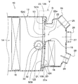
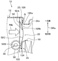
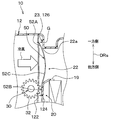
- the indoor air-conditioning unit 10 shown in FIG. 1 is arranged at a substantially central portion in the vehicle width direction of the inside of the instrument panel located at the frontmost portion of the vehicle interior.
- the indoor air-conditioning unit 10 has a case 12 that forms an outer shell thereof and also forms an air passage for blown air that is blown toward the vehicle interior.
- the case 12 is molded of a resin (for example, polypropylene) having a certain degree of elasticity and excellent strength.
- An air inflow space 14 into which the blown air from a blower unit (not shown) flows in is formed on the most upstream side of the air passage formed in the case 12.
- the blower unit is offset from the indoor air conditioning unit 10 on one side (for example, the passenger seat side) in the vehicle width direction.
- the blower unit includes an inside / outside air switching box that switches between the inside / outside air and the outside air, and a blower that blows the air introduced into the inside / outside air switching box.
- the evaporator 16 is arranged on the downstream side of the air flow in the air inflow space 14.
- the evaporator 16 is one of the devices constituting a vapor compression refrigeration cycle (not shown).
- the evaporator 16 is a cooling heat exchanger that cools the air introduced into the air inflow space 14 by evaporating the low-pressure refrigerant in the refrigeration cycle to exert an endothermic action.
- the heater core 18 is arranged on the downstream side of the air flow of the evaporator 16.
- the heater core 18 is a heating heat exchanger that heats the cold air by inflowing high-temperature cooling water that circulates in an engine cooling circuit (not shown) into the inside and exchanging heat between the cooling water and the cold air that has passed through the evaporator 16. ..
- a partition plate portion 19 allows a hot air passage 20 constituting an air passage for flowing cold air to the heater core 18 and a cold air bypassing the heater core 18 to flow.
- the cold air passage 22 constituting the air passage is formed in parallel.
- the hot air passage 20 and the cold air passage 22 are air passages through which air passes.
- a hot air opening 20a serving as an air inlet of the hot air passage 20 and a cold air opening 22a serving as an air inlet of the cold air passage 22 are provided inside the case 12.
- the warm air opening 20a is an opening formed by the hot air opening edge 21 provided inside the case 12.
- the cold air opening 22a is an opening formed by the cold air opening edge 23 provided inside the case 12.
- the hot air opening 20a and the cold air opening 22a form an opening of the air passage.
- an air mix door 50 for adjusting the air volume ratio between the cold air flowing into the hot air passage 20 and the cold air flowing into the cold air passage 22 is arranged between the evaporator 16 and the heater core 18. There is.
- the air mix door 50 constitutes a sliding door that opens and closes the air passage in the passage opening / closing device. That is, the air mix door 50 is composed of a slide door that is slidably arranged inside the case 12 and opens and closes the hot air opening 20a and the cold air opening 22a.
- the sliding door is not a film door that opens and closes by being wound around a drive shaft 30 and moves, but a door that opens and closes by reciprocating while maintaining a predetermined form. Sliding doors are also different from film doors in that they do not have holes for ventilation.
- the air mix door 50 moves upward in the figure as shown by the solid line in the figure, so that the passage opening of the warm air passage 20 increases. That is, when the air mix door 50 is displaced to the position shown by the solid line in the drawing, the opening area of the warm air opening 20a increases.
- the air mix door 50 moves downward in the figure as shown by the broken line in the figure, so that the passage opening of the cold air passage 22 increases. That is, when the air mix door 50 is displaced to the position indicated by the broken line in the drawing, the opening area of the cold air opening 22a increases.
- the indoor air conditioning unit 10 adjusts the drive position of the air mix door 50 to adjust the air volume ratio between the cold air flowing into the heater core 18 and the cold air flowing around the heater core 18, so that the temperature of the air blown into the vehicle interior is adjusted. Is adjusted.
- the air mix door 50 can slide and move inside the case 12 by the rotational force of the pinion 32 connected to the drive shaft 30. The details of the door structure of the air mix door 50 will be described later.
- the case 12 On the most downstream side of the air passage formed in the case 12, a plurality of openings for blowing out temperature-controlled air inside the case 12 into the vehicle interior are formed. Specifically, the case 12 is formed with three openings such as a defroster opening 24, a face opening 26, and a foot opening 28.
- the defroster opening 24 is an opening that blows air toward the inner surface side of the window glass on the front surface of the vehicle.
- the defroster opening 24 is opened and closed by a defroster door 25 provided inside the case 12.
- the defroster door 25 is rotationally driven by a servomotor or the like (not shown).
- the face opening 26 is an opening that blows air toward the upper body side of the occupant in the vehicle interior through a duct (not shown).
- the face opening 26 is opened and closed by a face door 27 provided inside the case 12.
- the face door 27 is rotationally driven by a servomotor or the like (not shown).
- the foot opening 28 is an opening that blows air toward the lower body side of the occupant in the vehicle interior through a duct (not shown).
- the foot opening 28 is opened and closed by a foot door 29 provided inside the case 12.
- the foot door 29 is rotationally driven by a servomotor or the like (not shown).
- FIGS. 2 to 5 the details of the door structure of the air mix door 50 will be described with reference to FIGS. 2 to 5.
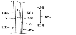
- the direction in which the air mix door 50 moves is shown as the door moving direction DRs
- the direction orthogonal to the door moving direction DRs on the plate surface of the air mix door 50 is shown as the door width direction DRw.
- the air mix door 50 includes a plate-shaped door body 52 and a pair of racks 54 and 55 that mesh with a pinion 32 connected to a drive shaft 30. There is.
- the door body 52 is made of a flexible thin plate member formed of a resin such as polypropylene.
- the door body 52 has a door front portion 521 located on the upstream side (that is, upwind side) of the air flow in the air passage, and a door back portion 522 located on the downstream side (that is, leeward side) of the air flow in the air passage. ing.
- the pair of racks 54 and 55 are formed so as to extend along the door moving direction DRs in the door front portion 521 of the door main body portion 52.
- the pair of racks 54 and 55 project from the door front surface portion 521 of the door body portion 52 toward the windward side.
- the pair of racks 54 and 55 are formed at a portion inside the both ends in the door width direction DRw.
- the pair of racks 54 and 55 are integrally molded with the door body 52. That is, the door body 52 and the pair of racks 54 and 55 are configured as integrally molded products.
- the pinion 32 is connected to the drive shaft 30 as shown in FIG.
- the drive shaft 30 is rotatably supported at both ends by bearing holes formed on the side wall surface of the case 12. Then, one end of the drive shaft 30 is coupled to a door drive device such as a servomotor.
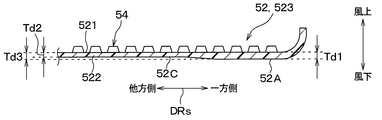
- the door body 52 includes a cold air side end 52A forming one end of the door moving direction DRs, a hot air side end 52B forming the other end of the door moving direction DRs, and a cold air side end 52A. It has a door intermediate portion 52C located between the hot air side end portion 52B and the door intermediate portion 52B.
- the cold air side end 52A is a door end facing the cold air opening edge 23 when the air mix door 50 is displaced to a closing position that closes the cold air opening 22a.
- the cold air side end portion 52A is curved in an arc shape so that one side of the door moving direction DRs protrudes toward the windward side.
- the warm air side end 52B is a door end facing the warm air opening edge 21 when the air mix door 50 is displaced to a closing position that closes the warm air opening 20a.
- the warm air side end 52B is curved in an arc shape so that the other side of the door moving direction DRs protrudes toward the windward side.
- the door intermediate portion 52C covers the cold air opening 22a when the air mix door 50 is displaced to the closing position where the cold air opening 22a is closed, and is displaced to the closing position where the air mix door 50 closes the hot air opening 20a. It is a portion that covers the warm air opening 20a at the time of the displacement.
- the door intermediate portion 52C has a plate thickness Td equivalent to that of the cold air side end portion 52A and the warm air side end portion 52B. As a result, the door intermediate portion 52C has the same rigidity as the cold air side end portion 52A and the hot air side end portion 52B.
- the door main body 52 is a main body central portion 523 sandwiched between the pair of racks 54 and 55 in the door width direction DRw, and a pair of main body side portions 524 located outside the pair of racks 54 and 55 in the door width direction DRw. Has 525.
- the case 12 is formed with a pair of guide rails 122 and 124 that slidably support the door main body 52 at positions corresponding to the pair of main body side portions 524 and 525 of the door main body 52.
- a pair of main body side portions 524 and 525 are interposed between the pair of guide rails 122 and 124.
- the guide rail 122 located on the windward side faces the door front portion 521 of the door body portion 52
- the guide rail 124 located on the leeward side faces the door body portion. It faces the back surface portion 522 of the door 52.
- the pair of guide rails 122 and 124 guide the movement of the air mix door 50 and extend along the door movement direction DRs.
- the pair of guide rails 122 and 124 have rail ends 122a and 124a that guide both ends of the pair of main body side portions 524 and 525 in the door moving direction DRs, and the rail end portions 122a, The 124a also extends along the door moving direction DRs.
- the pair of guide rails 122 and 124 are curved so as to bulge toward the leeward side so that the door main body 52 is supported at three points of the substantially central portion and the substantially both end portions of the door moving direction DRs. .. That is, the pair of guide rails 122 and 124 have a shape curved in an arc shape when viewed from the door width direction DRw. The distance between the pair of guide rails 122 and 124 is substantially constant in the extending direction.
- a pair of main body side portions 524 and 525 of the door main body portion 52 are inserted between the pair of guide rails 122 and 124.
- the door body 52 is flat in a single state, but when both ends thereof are inserted between the pair of guide rails 122 and 124, the door body 52 is elastically deformed along the curved shape of the pair of guide rails 122 and 124. doing.
- the door main body 52 is supported by a pair of guide rails 122 and 124 at three points, a substantially central portion and a substantially both end portions of the door moving direction DRs.
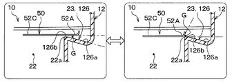
- the case 12 is formed with a cold air seal portion 126 facing the cold air side end portion 52A of the air mix door 50 when the air mix door 50 is displaced to the closed position of the cold air opening 22a. Further, the case 12 is formed with a warm air seal portion 128 facing the warm air side end portion 52B of the air mix door 50 when the air mix door 50 is displaced to the closed position of the warm air opening 20a.
- the cold air seal portion 126 constitutes a door facing wall portion that forms a gap flow path G extending along the door moving direction DRs with the cold air side end portion 52A.
- the distance between the cold air side end portion 52A and the cold air seal portion 126 is on the downstream side of the air flow so that the gap flow path G becomes a tapered flow path. It is configured to become smaller toward.
- the distance between the cold air side end portion 52A and the cold air sealing portion 126 decreases toward the downstream side in the flow direction of the air leaking through the gap flow path G (that is, the leaking air).
- This leaked air is air that leaks from between the door end and the door facing wall toward the passage downstream of the opening when the sliding door is displaced to a position where the opening is closed.
- the leaked air is air that leaks from between the cold air side end portion 52A and the cold air seal portion 126 toward the cold air passage 22 when the air mix door 50 is displaced to the closed position of the cold air opening 22a. ..
- the leaked air is mainly in the door moving direction DRs, unlike the flow direction of the air passing through the cold air opening 22a (that is, the mainstream air) when the air mix door 50 is displaced to the open position of the cold air opening 22a. It flows along.
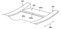
- the cold air seal portion 126 is provided with an inclined portion 126a that is inclined with respect to the door moving direction DRs so as to move away from the cold air side end portion 52A as the distance from the cold air opening 22a increases.
- the inclined portion 126a is provided at a position facing the cold air side end portion 52A when the air mix door 50 is displaced to a position where the cold air opening 22a is closed.
- the inclined portion 126a is configured such that the inclined angle ⁇ s formed by the inclined surface facing the cold air side end portion 52A and the door moving direction DRs is an acute angle. Further, the inclined portion 126a is inclined with respect to the door moving direction DRs so that the distance from the cold air side end portion 52A becomes continuously large as the distance from the cold air opening 22a increases. In other words, the inclined portion 126a is inclined with respect to the door moving direction DRs so that the passage area of the gap flow path G becomes continuously smaller toward the cold air opening 22a.
- the inclined portion 126a may have at least an inner surface facing the cold air side end portion 52A inclined with respect to the door moving direction DRs. For example, the inclined portion 126a may have an outer surface that does not face the cold air side end portion 52A extending along the door moving direction DRs.
- the portions constituting the pair of main body side portions 524 and 525 are guided by the pair of guide rails 122 and 124. Therefore, the inclined portion 126a is not provided at a portion of the cold air sealing portion 126 facing the pair of main body side portions 524 and 525. That is, the inclined portion 126a is provided at a portion of the cold air sealing portion 126 facing the central portion 523 of the main body.
- the cold air seal portion 126 is provided with a flat portion 126b at a position closer to the cold air opening 22a than the inclined portion 126a and having a smaller inclination angle with respect to the door moving direction DRs than the inclined portion 126a.
- the flat portion 126b is provided at a position facing the cold air side end portion 52A when the air mix door 50 is displaced to a position where the cold air opening 22a is closed.
- the flat portion 126b is a portion of the cold air sealing portion 126 that is connected to the cold air opening 22a.
- the flat portion 126b is closer to the cold air side end portion 52A than the inclined portion 126a so that the distance from the cold air side end portion 52A is the smallest than that of the inclined portion 126a.
- the flat portion 126b extends along the door moving direction DRs so that the distance from the cold air opening 22a is substantially constant.
- the flat portion 126b has a flat shape so as to extend substantially parallel to the portion of the cold air side end portion 52A facing the cold air seal portion 126.
- the length of the flat portion 126b in the door moving direction DRs is smaller than the length in the door moving direction DRs of the inclined portion 126a.
- the flat portion 126b is inclined with respect to the door moving direction DRs if the gap flow path G formed between the flat portion 126b and the cold air opening 22a is configured so as not to become a divergent flow path. You may be doing it.
- the vehicle air conditioner includes a blower, a door drive device that rotationally drives the drive shaft 30, and an air conditioner control device that controls the operation of the servomotors that drive the doors 25, 27, and 29.
- the air conditioning controller consists of a well-known microcomputer including a processor, memory, etc. and its peripheral circuits.
- This air-conditioning control device stores an air-conditioning control program stored in a memory, and controls the operation of a controlled device connected to the output side by performing various arithmetic processes based on the program.
- the operation panel is provided with an operation switch for turning on / off the air conditioning in the vehicle interior and a temperature setting switch for setting the set temperature in the vehicle interior.
- the vehicle air conditioner executes the air conditioner control program stored in the memory. That is, the air conditioning controller reads the detection signal of the sensor group and the operation signal of the operation panel, and calculates the target blowing temperature TAO of the air blown into the vehicle interior based on various signals. Then, the air conditioning control device determines the rotation speed of the blower, the drive position of the air mix door 50, and the open / closed state of each of the doors 25, 27, and 29 based on the target blowout temperature TAO and the like, and the determined control state can be obtained. The control signal is output to various controlled devices. The air conditioning controller periodically executes a series of routines such as reading various signals, determining a control state, and outputting control signals to various controlled devices.
- the air conditioning controller When the air conditioning controller outputs a control signal to a door drive device (not shown) to rotate drive the drive shaft 30, the pinion 32 connected to the drive shaft 30 meshes with the racks 54 and 55 provided on the door body 52. , The air mix door 50 slides and moves.
- the cold air adjusted to a desired temperature by the evaporator 16 bypasses the heater core 18. After flowing like this, it is blown into the vehicle interior through a predetermined opening. According to this, air having a temperature lower than that outside the passenger compartment is provided to the passenger compartment.
- the air passing through the evaporator 16 reaches a desired temperature in the heater core 18. After being heated, it is blown into the vehicle interior through a predetermined opening. According to this, air having a temperature higher than that outside the passenger compartment is provided to the passenger compartment.
- the sealing property between the cold air sealing portion 126 and the cold air side end portion 52A may be insufficient.
- the air mix door 50 is self-excited by forming a minute gap flow path G extending in the door moving direction DRs between the cold air seal portion 126 and the cold air side end portion 52A. It may vibrate.
- the air mix door 50 self-excitedly vibrates, an abnormal noise is generated due to a collision between the cold air seal portion 126 and the cold air side end portion 52A.
- FIG. 8 is an explanatory diagram for explaining the door structure CE of the air mix door D which is a comparative example of the present embodiment.
- the door end DE is provided so that the gap flow path G formed between the door end DE of the air mix door D and the cold air seal portion HS of the case H becomes a divergent flow path.
- the distance between the air and the cold air seal portion HS increases toward the downstream side of the air flow.
- the door structure CE is provided with a curved portion R that curves in an arc shape with respect to the cold air sealing portion HS so as to move away from the cold air side end portion 52A as it approaches the cold air opening 22a.
- the door end DE of the air mix door D corresponds to the cold air side end 52A of the air mix door 50 of the present embodiment.
- the cold air seal portion HS of the case H corresponds to the cold air seal portion 126 of the case 12 of the present embodiment.
- the door structure CE of the comparative example is formed between the door end DE and the cold air seal portion HS when the air mix door 50 is in the closed position or the slight opening position of the cold air opening 22a.
- the gap flow path G to be formed becomes a divergent flow path.
- the door end DE of the air mix door D approaches the cold air seal portion HS of the case H due to vibration as shown by the arrow A.
- the case where the time is changing is shown.
- the rate of change in the flow path area of the gap flow path G per unit time is larger on the inlet side than on the outlet side. That is, the rate of increase in the pressure loss of the gap flow path G per unit time is larger on the inlet side than on the outlet side, and the increase in the flow path resistance is dominant on the inlet side.
- the rate of change in the flow path area of the gap flow path G per unit time is smaller than that on the inlet side, so that the fluid inertia becomes dominant.
- the inflow amount of air into the gap flow path G sharply decreases.
- the pressure in the gap flow path G decreases.
- the unsteady fluid force Fp acts on the air mix door 50.
- This unsteady fluid force Fp acts in the same direction as the vibration as a force in the direction in which the door end DE is brought closer to the cold air seal portion HS, and therefore acts in the direction of amplifying the vibration.
- the door end DE of the air mix door D is separated from the cold air seal portion HS of the case H by vibration as shown by the arrow B.
- the case where the time changes with the speed is shown.
- the rate of change in the flow path area of the gap flow path G per unit time is larger on the inlet side than on the outlet side. That is, the reduction rate of the pressure loss of the gap flow path G per unit time is larger on the inlet side than on the outlet side, and the reduction of the flow path resistance is dominant on the inlet side.
- the rate of change in the flow path area of the gap flow path G per unit time is smaller than that on the inlet side, so that the fluid inertia becomes dominant.
- the unsteady fluid force acts on the air mix door D in the direction of amplifying the vibration, so that the vibration is likely to occur.
- the cold air side end portion 52A of the air mix door 50 changes with time at a speed in the direction approaching the cold air seal portion 126.
- the rate of change in the flow path area of the gap flow path G per unit time is larger on the outlet side than on the inlet side. That is, the rate of increase in pressure loss of the gap flow path G per unit time is larger on the outlet side than on the inlet side, and the increase in flow path resistance is dominant on the outlet side.
- the rate of change in the flow path area of the gap flow path G per unit time is smaller than that on the outlet side, so that the fluid inertia becomes dominant.
- the unsteady fluid force Fr acts on the air mix door 50.
- This unsteady fluid force Fr acts in the direction opposite to the vibration as a force in the direction of separating the cold air side end portion 52A from the cold air seal portion 126, and thus acts in the direction of attenuating the vibration.
- the rate of change in the flow path area of the gap flow path G per unit time is larger on the outlet side than on the inlet side. That is, the reduction rate of the pressure loss of the gap flow path G per unit time is larger on the outlet side than on the inlet side, and the reduction in the flow path resistance is dominant on the outlet side.
- the rate of change in the flow path area of the gap flow path G per unit time is smaller than that on the outlet side, so that the fluid inertia becomes dominant.
- the unsteady fluid force Fp acts on the air mix door 50.
- This unsteady fluid force Fp acts in the direction opposite to the vibration as a force in the direction of bringing the cold air side end portion 52A closer to the cold air seal portion 126, and thus acts in the direction of attenuating the vibration.
- the unsteady fluid force acts on the air mix door 50 in the direction of attenuating the vibration, so that the effect of suppressing the self-excited vibration can be sufficiently obtained. be able to.
- the present inventors verified the self-excited vibration of the sliding door with an actual machine. According to this verification, in the door structure CE of the comparative example, the distance between the door end DE and the cold air seal portion HS is equal to or greater than the first reference value Gs, and the pressure difference between the front and rear of the air mix door D is the first reference difference ⁇ P. It was caused by the above. On the other hand, in the door structure of the present embodiment, the distance between the cold air side end portion 52A and the cold air seal portion 126 is at least twice the first reference value Gs, and the pressure difference between the front and rear of the air mix door 50 is the second. It was confirmed that it did not occur even if it was 3 times or more of 1 reference difference ⁇ P.
- the distance between the cold air side end portion 52A of the air mix door 50 and the cold air seal portion 126 of the case 12 becomes smaller toward the downstream side of the air flow. According to this, since the unsteady fluid force acts on the air mix door 50 in the direction of attenuating the vibration, the self-excited vibration of the air mix door 50 can be suppressed. As a result, it is possible to suppress the generation of abnormal noise due to the self-excited vibration of the air mix door 50.
- the door structure of the present embodiment it is not necessary to form a spring structure or attach a bristle material or packing to the air mix door 50, so that the air mix door 50 can be manufactured easily. It is possible to suppress the self-excited vibration of the air mix door 50 while suppressing the deterioration of the air mix door 50.
- the gap flow path G formed between the cold air side end portion 52A and the cold air seal portion 126 is a tapered flow path, so that the cold air side end portion 52A and the cold air are cold air.
- the sealing surface in contact with the sealing portion 126 becomes smaller. That is, since the area of contact between the cold air side end portion 52A and the cold air seal portion 126 is reduced, the door operating force required for opening and closing the cold air opening 22a at the air mix door 50 can be reduced.
- the sealing surface in which the cold air side end portion 52A and the cold air sealing portion 126 are in contact with each other becomes smaller. Can be reduced.
- the cold air seal portion 126 includes an inclined portion 126a that is inclined with respect to the door moving direction DRs so as to move away from the cold air side end portion 52A as the distance from the cold air opening 22a increases.
- a tapered flow path can be formed between the cold air seal portion 126 and the cold air side end portion 52A.
- the cold air seal portion 126 is provided with a flat portion 126b at a position closer to the cold air opening 22a than the inclined portion 126a and having a smaller inclination angle with respect to the door moving direction DRs than the inclined portion 126a. According to this, when the air mix door 50 is displaced to the closed position, the contact area (that is, the seal area) between the cold air side end portion 52A of the air mix door 50 and the cold air seal portion 126 can be easily secured. This greatly contributes to the improvement of the sealing property of the air mix door 50.
- the end of the guide rail 124 on the leeward side of the pair of guide rails 122 and 124 is inclined with respect to the door moving direction DRs as in the case of the cold air seal portion 126, the wind pressure when the cold air opening 22a is closed.
- the cold air side end portion 52A is tilted with respect to the door moving direction DRs.
- the inclination of the cold air side end portion 52A with respect to the door moving direction DRs becomes a factor that makes it difficult to displace the air mix door 50 in the door moving direction DRs.
- the entire pair of guide rails 122 and 124 that guide the movement of the air mix door 50 extends along the door movement direction DRs.
- the end portion of the guide rail 124 on the leeward side extends along the door moving direction DRs, unlike the cold air seal portion 126, as shown in FIG. According to this, even if the inclined portion 126a is formed on the cold air sealing portion 126, the air mix door 50 can be displaced in the door moving direction DRs along the pair of guide rails 122 and 124. That is, according to the door structure of the present embodiment, the air mix door 50 can be displaced in the door moving direction DRs, and a tapered flow path can be formed between the cold air seal portion 126 and the cold air side end portion 52A.
- the flat portion 126b is formed with respect to the cold air sealing portion 126, but the cold air sealing portion 126 is not limited to this.
- the cold air seal portion 126 may be formed, for example, so that the inclined portion 126a is connected to the cold air opening 22a.
- the cold air seal portion 126 is provided with an inclined portion 126c that is inclined stepwise with respect to the door moving direction DRs so as to move away from the cold air side end portion 52A as the distance from the cold air opening 22a increases. ing.
- the inclined portion 126c is provided at a position facing the cold air side end portion 52A when the air mix door 50 is displaced to a position where the cold air opening 22a is closed.
- the inclined portion 126c is inclined stepwise with respect to the door moving direction DRs so that the distance from the cold air side end portion 52A gradually increases as the distance from the cold air opening 22a increases.
- the inclined portion 126c is inclined stepwise with respect to the door moving direction DRs so that the passage area of the gap flow path G gradually decreases toward the cold air opening 22a.
- the inclined portion 126c may have at least an inner surface facing the cold air side end portion 52A inclined stepwise with respect to the door moving direction DRs.
- the door structure of the air mix door 50 of the present embodiment can obtain the same effect as that of the first embodiment from the same or the same configuration as that of the first embodiment.
- the cold air seal portion 126 is provided with the inclined portion 126c that is inclined in a stepped manner, but the cold air seal portion 126 is not limited to this.
- the cold air seal portion 126 may be provided with, for example, an inclined portion having each of a continuously inclined portion and a stepwise inclined portion. Further, the cold air seal portion 126 may be formed with an inclined portion having a curved surface whose tangent line intersects the door moving direction DRs.
- the cold air seal portion 126 is not provided with the inclined portion 126a and extends along the door moving direction DRs. That is, the cold air seal portion 126 has a flat shape as a whole along the door moving direction DRs.
- the air mix door 50 when the air mix door 50 is displaced to a position where the cold air opening 22a is closed, the cold air side end portion 52A of the air mix door 50 is separated from the cold air seal portion 126 as the air mix door 50 moves away from the cold air opening 22a. It is inclined with respect to the door moving direction DRs.
- the cold air side end portion 52A is configured so that the inclination angle ⁇ d formed with the door moving direction DRs is an acute angle.
- a bent portion 52D which is a starting point of bending, is provided at a connecting portion between the cold air side end portion 52A and the door intermediate portion 52C.
- the air mix door 50 has a corner portion formed by the bent portion 52D, so that the cold air side end portion 52A is inclined with respect to the door moving direction DRs.
- the air mix door 50 having such a shape can be obtained through a simple manufacturing method such as forming racks 54 and 55 by press molding and then bending the formed body by bending.
- the air mix door 50 may be manufactured by another manufacturing method.
- the door structure of the air mix door 50 of the present embodiment can obtain the same effect as that of the first embodiment from the same or the same configuration as that of the first embodiment.
- the cold air seal portion 126 as the cold air side end portion 52A moves away from the cold air opening 22a when the air mix door 50 is displaced to the closed position of the cold air opening 22a. It is inclined with respect to the door moving direction DRs so as to be away from. By inclining the cold air side end portion 52A of the air mix door 50 in this way, a tapered flow path can be formed between the cold air seal portion 126 and the cold air side end portion 52A.
- the air mix door 50 of the present embodiment can be obtained through a simple manufacturing method. Therefore, according to the door structure of the air mix door 50 of the present embodiment, it is possible to suppress the self-excited vibration of the air mix door 50 while suppressing the deterioration of the manufacturability of the air mix door 50.
- the air mix door 50 is illustrated in which a bent portion 52D serving as a starting point of bending is provided at a connecting portion between the cold air side end portion 52A and the door intermediate portion 52C, but the air mix door 50 is illustrated. Is not limited to this.
- the air mix door 50 may be provided with, for example, an arc-shaped curved portion serving as a starting point of bending at the connecting portion between the cold air side end portion 52A and the door intermediate portion 52C.
- the starting point of bending is not limited to the connecting portion between the cold air side end portion 52A and the door intermediate portion 52C, and may be provided on the door intermediate portion 52C side or the cold air side end portion 52A side of the connecting portion.
- the cold air seal portion 126 is not provided with the inclined portion 126a described in the first embodiment, but the door structure of the air mix door 50 is not limited to this.
- the door structure of the air mix door 50 is realized, for example, in that the cold air seal portion 126 is provided with the inclined portion 126a described in the first embodiment and the cold air side end portion 52A is inclined with respect to the door moving direction DRs. You may be.
- the gap flow path G formed between the cold air side end portion 52A and the cold air seal portion 126 may be a tapered flow path.
- the cold air seal portion 126 is located on the windward side as it moves away from the cold air opening 22a, or the cold air side end 52A is a cold air opening. It may be located on the leeward side as it moves away from the portion 22a.
- the air mix door 50 has a cold air side end portion 52A, a hot air side end portion 52B, and a door intermediate portion 52C.
- the door intermediate portion 52C has at least a part lower rigidity than the cold air side end portion 52A.
- the plate thickness Td2 of the door intermediate portion 52C is smaller than the plate thickness Td1 of the cold air side end portion 52A.
- the plate thickness Td2 of the main body central portion 523 that receives wind pressure when the air mix door 50 is displaced to the closed position of the cold air opening 22a is the plate thickness Td1 of the cold air side end portion 52A.
- the plate thickness Td3 of the pair of main body side portions 524 and 525 guided by the pair of guide rails 122 and 124 is about the same as the plate thickness Td1 of the cold air side end portion 52A.
- the door intermediate portion 52C and the cold air side end portion 52A are flush with each other at the door front portion 521, and the door intermediate portion 52C is the cold air side end portion at the door rear portion 522. It is recessed on the windward side of 52A.
- the door intermediate portion 52C is recessed on the leeward side of the cold air side end portion 52A at the door front portion 521, and the door intermediate portion 52C and the cold air side end portion 52A are formed at the door back portion 522. May be flush.
- the door intermediate portion 52C is recessed on the leeward side of the cold air side end 52A at the door front portion 521, and the door intermediate portion 52C is recessed on the leeward side of the cold air side end 52A at the door rear end 522. May be dented on the windward side.
- the door structure of the air mix door 50 of the present embodiment can obtain the same effect as that of the first embodiment from the same or the same configuration as that of the first embodiment.
- the rigidity of the door intermediate portion 52C of the air mix door 50 is small. Therefore, as shown in FIG. 18, when the air mix door 50 is displaced to the closed position of the cold air opening 22a, the door intermediate portion 52C becomes convex toward the leeward side due to the wind pressure acting on the air mix door 50. It becomes easy to be deformed into a shape.
- the cold air side end portion 52A moves away from the cold air seal portion 126 as the cold air opening 22a moves away from the door moving direction DRs. Tilt.
- the door structure of the air mix door 50 of the present embodiment can also suppress the self-excited vibration of the air mix door 50 while suppressing the deterioration of the manufacturability of the air mix door 50.
- the door structure of the air mix door 50 is not limited to this.
- the cold air seal portion 126 is provided with an inclined portion 126a. It does not have to be. That is, in the door structure of the air mix door 50 shown in the fourth embodiment, for example, as shown in FIG. 19, the cold air seal portion 126 is not provided with the inclined portion 126a, and the cold air seal portion 126 is in the door moving direction. It may extend along the DRs.
- the plate thickness Td3 of the pair of main body side portions 524 and 525 is about the same as the plate thickness Td1 of the cold air side end portion 52A.
- the door intermediate portion 52C is not limited to this. In the door intermediate portion 52C, for example, the plate thickness Td3 of the pair of main body side portions 524 and 525 may be smaller than the plate thickness Td1 of the cold air side end portion 52A.
- the rigidity of the door intermediate portion 52C is reduced by reducing the plate thickness Td2 of the door intermediate portion 52C, but the air mix door 50 is not limited to this.
- the pair of guide rails 122, 124 and the seal portions 126, 128 have a curved shape so as to bulge toward the downstream side of the air flow, but the present invention is not limited to this.
- it may have a linear shape.
- the air mix door 50 is not limited to resin, and may be made of, for example, a thin metal plate.
- the gap flow path G between the cold air side end portion 52A and the cold air seal portion 126 is configured to be a tapered flow path, but the door structure of the air mix door 50 is Not limited to this.
- the warm air side end portion 52B and the warm air side end portion 52B and the warm air side end portion 52B and the warm air side end portion 52B are warm so that the gap flow path formed between the warm air side end portion 52B and the warm air seal portion 128 becomes a tapered flow path.
- the distance from the wind seal portion 128 may become smaller toward the downstream side of the air flow. According to this, since the unsteady fluid force acts on the warm air side end portion 52B of the air mix door 50 in the direction of attenuating the vibration, the self-excited vibration of the air mix door 50 can be suppressed.
- the door structure of the air mix door 50 has a gap formed between the gap flow path G between the cold air side end portion 52A and the cold air seal portion 126, the hot air side end portion 52B, and the hot air seal portion 128.
- Each of the flow paths may be configured to be a tapered flow path. According to this, the unsteady fluid force acts in the direction of attenuating the vibration on each of the cold air side end portion 52A and the warm air side end portion 52B of the air mix door 50, so that the self-excited vibration of the air mix door 50 is suppressed. can do.
- the passage opening / closing device of the present disclosure can be applied to, for example, an inside / outside air switching box having an inside / outside air switching door, and a door structure of a mode switching door such as a defroster door 25, a face door 27, and a foot door 29. Further, the passage opening / closing device of the present disclosure can be applied not only to a vehicle air conditioner but also to various devices for opening / closing an air passage.
- the elements constituting the embodiment are not necessarily essential except when it is clearly stated that they are essential and when they are clearly considered to be essential in principle.
- the aisle switchgear comprises a case and a sliding door that opens and closes an opening in the case.
- the sliding door constitutes one end of the sliding door in the door moving direction and includes a door end facing the opening edge when the sliding door is displaced to a closing position that closes the opening.
- the opening edge includes a door facing wall portion that faces the door end when the sliding door is displaced to the closed position and forms a gap flow path extending along the door moving direction with the door end.
- the distance between the door end and the door facing wall becomes smaller toward the downstream side of the air flow so that the gap flow path becomes a tapered flow path.
- the door facing wall portion includes an inclined portion that inclines with respect to the door moving direction so as to move away from the door end portion as the distance from the opening increases.
- the inclined portion is provided on the door facing wall portion, a tapered flow path can be formed between the door facing wall portion and the door end portion.
- the door facing wall portion is provided with a flat portion having a smaller inclination angle with respect to the door moving direction than the inclined portion at a position closer to the opening than the inclined portion.
- a flat portion having an inclination angle smaller than that of the inclined portion is provided with respect to the door facing wall portion, when the sliding door is displaced to the closed position, the door end portion of the sliding door and the door facing wall portion are provided.
- Contact area that is, seal area
- the door end is inclined with respect to the door moving direction so as to move away from the opening when the sliding door is displaced to the closed position and away from the door facing wall.
- the sliding door has a door intermediate portion that covers the opening when the sliding door is displaced to the closed position.
- the middle part of the door is at least partly less rigid than the end part of the door.
- the middle part of the door is deformed into a convex shape toward the leeward side due to the wind pressure acting on the sliding door when the sliding door is displaced to the closed position. It will be easier.
- the middle part of the door becomes convex toward the leeward side, the sliding door inclines with respect to the door moving direction so that the door end portion moves away from the door facing wall portion as it moves away from the opening. Therefore, even if the rigidity of the door intermediate portion of the sliding door is reduced, a tapered flow path can be formed between the door facing wall portion and the door end portion.
- the passage opening / closing device includes a guide rail that guides the movement of the sliding door.
- the guide rail extends along the direction of movement of the door.
- the sliding door can be displaced along the guide rail in the door moving direction, and a tapered flow path can be formed between the door facing wall portion and the door end portion.
Landscapes
- Engineering & Computer Science (AREA)
- Mechanical Engineering (AREA)
- Physics & Mathematics (AREA)
- Thermal Sciences (AREA)
- Chemical & Material Sciences (AREA)
- Combustion & Propulsion (AREA)
- General Engineering & Computer Science (AREA)
- Air-Conditioning For Vehicles (AREA)
Abstract
The purpose of the present disclosure is to provide a passage opening/closing device that is capable of suppressing self-excited vibration of a slide door while suppressing a degradation in the manufacturability of the slide door. This passage opening/closing device comprises: a case (12) in which an opening edge part (23) that forms an opening section (22a) of an air passage (22) is provided; and a slide door (50) that is slidably disposed inside the case and opens/closes the opening section. The slide door includes a door end section (52A) that constitutes one end section in the door movement direction of the slide door and faces the opening edge part when the slide door is displaced to a closing position for closing the opening section. The opening edge part includes a door facing wall section (126) that faces the door end section when the slide door is displaced to the closed position and that forms a gap flow passage (G) extending in the door movement direction between the door end section and the door facing wall section. In the door end section and the door facing wall section, a gap between the door end section and the door facing wall section becomes smaller toward the downstream side of an air flow so that the gap flow passage serves as a tapered flow passage.
Description
本出願は、2019年10月3日に出願された日本特許出願番号2019-183215号に基づくもので、ここにその記載内容が参照により組み入れられる。
This application is based on Japanese Patent Application No. 2019-183215 filed on October 3, 2019, the contents of which are incorporated herein by reference.
本開示は、空気通路を開閉する通路開閉装置に関する。
The present disclosure relates to a passage opening / closing device for opening / closing an air passage.
従来、通路開閉装置として、スライドドアの自励振動を抑制するために、スライドドアの背面に振動を減衰させる減衰機構が設けられたものが知られている(例えば、特許文献1参照)。
Conventionally, as a passage opening / closing device, in order to suppress the self-excited vibration of the sliding door, a damping mechanism for damping the vibration is provided on the back surface of the sliding door (see, for example, Patent Document 1).
ところで、特許文献1に記載の発明は、スライドドアに対してバネ構造を造形したり、柔毛材やパッキンを貼付したりする必要があり、スライドドアの製造性が悪化してしまう。このことは本発明者らの鋭意検討の末に見出された。
本開示は、スライドドアの製造性の悪化を抑えつつ、スライドドアの自励振動を抑制可能な通路開閉装置を提供することを目的とする。 By the way, in the invention described in Patent Document 1, it is necessary to form a spring structure for the sliding door, or to attach a bristle material or packing to the sliding door, which deteriorates the manufacturability of the sliding door. This was discovered after diligent studies by the present inventors.
An object of the present disclosure is to provide a passage opening / closing device capable of suppressing self-excited vibration of a sliding door while suppressing deterioration of manufacturability of the sliding door.
本開示の1つの観点によれば、通路開閉装置は、
空気通路の開口部を形成する開口縁部が内部に設けられたケースと、
ケースの内部にスライド移動可能に配置されて開口部を開閉するスライドドアと、を備え、
スライドドアは、スライドドアのドア移動方向の一方側の端部を構成するとともに、スライドドアが開口部を閉鎖する閉鎖位置に変位すると開口縁部に対向するドア端部を含み、
開口縁部は、スライドドアが閉鎖位置に変位した際にドア端部に対向するとともにドア端部との間にドア移動方向に沿って延びる隙間流路を形成するドア対向壁部を含み、
ドア端部およびドア対向壁部は、隙間流路が先細り流路となるように、ドア端部とドア対向壁部との間隔が空気流れ下流側に向かって小さくなっている。 According to one aspect of the present disclosure, the passage opening / closing device is
A case in which an opening edge forming an opening of an air passage is provided inside, and a case
It is equipped with a sliding door that is arranged so that it can be slidably moved inside the case and opens and closes the opening.
The sliding door constitutes one end of the sliding door in the door moving direction and includes a door end that faces the opening edge when the sliding door is displaced to a closing position that closes the opening.
The opening edge includes a door facing wall portion that faces the door end when the sliding door is displaced to the closed position and forms a gap flow path extending along the door moving direction with the door end.
At the door end and the door facing wall, the distance between the door end and the door facing wall becomes smaller toward the downstream side of the air flow so that the gap flow path becomes a tapered flow path.
このように、スライドドアのドア端部とケースの開口縁部のドア対向壁部との間隔を空気流れ下流側に向かって小さくすれば、スライドドアに対して振動を減衰させる方向に非定常流体力が作用するので、スライドドアの自励振動を抑制することができる。加えて、本開示の通路開閉装置は、従来の如く、スライドドアに対して、バネ構造を造形したり、柔毛材やパッキンを貼付したりすることがないので、スライドドアの製造性の悪化を抑えつつ、スライドドアの自励振動を抑制することができる。
In this way, if the distance between the door end of the sliding door and the door facing wall at the opening edge of the case is reduced toward the downstream side of the air flow, the unsteady flow in the direction of damping the vibration with respect to the sliding door. Since physical strength acts, the self-excited vibration of the sliding door can be suppressed. In addition, the passage opening / closing device of the present disclosure does not form a spring structure or attach a bristle material or packing to the sliding door as in the conventional case, so that the manufacturability of the sliding door deteriorates. It is possible to suppress the self-excited vibration of the sliding door while suppressing the above.
なお、各構成要素等に付された括弧付きの参照符号は、その構成要素等と後述する実施形態に記載の具体的な構成要素等との対応関係の一例を示すものである。
Note that the reference symbols in parentheses attached to each component or the like indicate an example of the correspondence between the component or the like and the specific component or the like described in the embodiment described later.
以下、本開示の実施形態について図面を参照して説明する。なお、以下の実施形態において、先行する実施形態で説明した事項と同一もしくは均等である部分には、同一の参照符号を付し、その説明を省略する場合がある。また、実施形態において、構成要素の一部だけを説明している場合、構成要素の他の部分に関しては、先行する実施形態において説明した構成要素を適用することができる。以下の実施形態は、特に組み合わせに支障が生じない範囲であれば、特に明示していない場合であっても、各実施形態同士を部分的に組み合わせることができる。
Hereinafter, embodiments of the present disclosure will be described with reference to the drawings. In the following embodiments, the same reference numerals may be assigned to parts that are the same as or equivalent to those described in the preceding embodiments, and the description thereof may be omitted. Further, when only a part of the component is described in the embodiment, the component described in the preceding embodiment can be applied to the other part of the component. The following embodiments can be partially combined with each other as long as the combination does not cause any trouble, even if not explicitly stated.
(第1実施形態)
本実施形態について、図1~図13を参照して説明する。本実施形態では、本開示の通路開閉装置を車両用空調装置における室内空調ユニット10に適用した例について説明する。 (First Embodiment)
This embodiment will be described with reference to FIGS. 1 to 13. In the present embodiment, an example in which the passage opening / closing device of the present disclosure is applied to the indoorair conditioner unit 10 in the vehicle air conditioner will be described.
本実施形態について、図1~図13を参照して説明する。本実施形態では、本開示の通路開閉装置を車両用空調装置における室内空調ユニット10に適用した例について説明する。 (First Embodiment)
This embodiment will be described with reference to FIGS. 1 to 13. In the present embodiment, an example in which the passage opening / closing device of the present disclosure is applied to the indoor
図1に示す室内空調ユニット10は、車室内の最前部に位置するインストルメントパネルの内側のうち、車両幅方向の略中央部に配置されている。室内空調ユニット10は、その外殻を形成すると共に、車室内へ向かって送風される送風空気の空気通路を形成するケース12を有している。ケース12は、ある程度の弾性を有し、強度的にも優れた樹脂(例えば、ポリプロピレン)にて成形されている。
The indoor air-conditioning unit 10 shown in FIG. 1 is arranged at a substantially central portion in the vehicle width direction of the inside of the instrument panel located at the frontmost portion of the vehicle interior. The indoor air-conditioning unit 10 has a case 12 that forms an outer shell thereof and also forms an air passage for blown air that is blown toward the vehicle interior. The case 12 is molded of a resin (for example, polypropylene) having a certain degree of elasticity and excellent strength.
ケース12に形成された空気通路の最上流側には、図示しないブロワユニットからの送風空気が流入する空気流入空間14が形成されている。ブロワユニットは、図示しないが、室内空調ユニット10に対して車両幅方向の一方側(例えば、助手席側)にオフセット配置されている。ブロワユニットは、車室内空気と車室外空気とを切り替え導入する内外気切替箱と、内外気切替箱に導入された空気を送風する送風機とを含んで構成されている。
An air inflow space 14 into which the blown air from a blower unit (not shown) flows in is formed on the most upstream side of the air passage formed in the case 12. Although not shown, the blower unit is offset from the indoor air conditioning unit 10 on one side (for example, the passenger seat side) in the vehicle width direction. The blower unit includes an inside / outside air switching box that switches between the inside / outside air and the outside air, and a blower that blows the air introduced into the inside / outside air switching box.
ケース12の内部には、空気流入空間14の空気流れ下流側に、蒸発器16が配置されている。蒸発器16は、図示しない蒸気圧縮式の冷凍サイクルを構成する機器の1つである。蒸発器16は、冷凍サイクル内における低圧冷媒を蒸発させて吸熱作用を発揮させることで、空気流入空間14に導入された空気を冷却する冷却用熱交換器である。
Inside the case 12, the evaporator 16 is arranged on the downstream side of the air flow in the air inflow space 14. The evaporator 16 is one of the devices constituting a vapor compression refrigeration cycle (not shown). The evaporator 16 is a cooling heat exchanger that cools the air introduced into the air inflow space 14 by evaporating the low-pressure refrigerant in the refrigeration cycle to exert an endothermic action.
また、ケース12の内部には、蒸発器16の空気流れ下流側に、ヒータコア18が配置されている。ヒータコア18は、図示しないエンジンの冷却回路を循環する高温の冷却水を内部に流入させ、冷却水と蒸発器16を通過した冷風との熱交換によって、冷風を加熱する加熱用熱交換器である。
Further, inside the case 12, the heater core 18 is arranged on the downstream side of the air flow of the evaporator 16. The heater core 18 is a heating heat exchanger that heats the cold air by inflowing high-temperature cooling water that circulates in an engine cooling circuit (not shown) into the inside and exchanging heat between the cooling water and the cold air that has passed through the evaporator 16. ..
ケース12の内部のうち、蒸発器16の空気流れ下流側には、仕切板部19によって、ヒータコア18に冷風を流す空気通路を構成する温風通路20と、ヒータコア18を迂回して冷風を流す空気通路を構成する冷風通路22とが並列に形成されている。温風通路20および冷風通路22は空気が通過する空気通路である。
Inside the case 12, on the downstream side of the air flow of the evaporator 16, a partition plate portion 19 allows a hot air passage 20 constituting an air passage for flowing cold air to the heater core 18 and a cold air bypassing the heater core 18 to flow. The cold air passage 22 constituting the air passage is formed in parallel. The hot air passage 20 and the cold air passage 22 are air passages through which air passes.
具体的には、ケース12の内部には、温風通路20の空気入口となる温風開口部20aおよび冷風通路22の空気入口となる冷風開口部22aが設けられている。温風開口部20aは、ケース12の内側に設けられた温風開口縁部21によって形成される開口部である。冷風開口部22aは、ケース12の内側に設けられた冷風開口縁部23によって形成される開口部である。温風開口部20aおよび冷風開口部22aは、空気通路の開口部を構成する。
Specifically, inside the case 12, a hot air opening 20a serving as an air inlet of the hot air passage 20 and a cold air opening 22a serving as an air inlet of the cold air passage 22 are provided. The warm air opening 20a is an opening formed by the hot air opening edge 21 provided inside the case 12. The cold air opening 22a is an opening formed by the cold air opening edge 23 provided inside the case 12. The hot air opening 20a and the cold air opening 22a form an opening of the air passage.
ケース12の内部のうち、蒸発器16とヒータコア18との間には、温風通路20に流入する冷風と冷風通路22に流入する冷風との風量割合を調整するエアミックスドア50が配置されている。
Inside the case 12, an air mix door 50 for adjusting the air volume ratio between the cold air flowing into the hot air passage 20 and the cold air flowing into the cold air passage 22 is arranged between the evaporator 16 and the heater core 18. There is.
エアミックスドア50は、通路開閉装置における空気通路を開閉するスライドドアを構成している。すなわち、エアミックスドア50は、ケース12の内部にスライド移動可能に配置されて温風開口部20aおよび冷風開口部22aを開閉するスライドドアで構成されている。スライドドアは、駆動軸30に巻き取られて移動することにより開閉動作を行うフィルムドアではなく、所定の形態が維持された状態で往復動することにより開閉動作を行うドアである。スライドドアは、通風用の孔が形成されていない点もフィルムドアとは異なる。
The air mix door 50 constitutes a sliding door that opens and closes the air passage in the passage opening / closing device. That is, the air mix door 50 is composed of a slide door that is slidably arranged inside the case 12 and opens and closes the hot air opening 20a and the cold air opening 22a. The sliding door is not a film door that opens and closes by being wound around a drive shaft 30 and moves, but a door that opens and closes by reciprocating while maintaining a predetermined form. Sliding doors are also different from film doors in that they do not have holes for ventilation.
室内空調ユニット10は、エアミックスドア50が、図中の実線で示すように図中上方側に移動することで、温風通路20の通路開度が増加する。すなわち、エアミックスドア50が図中の実線で示す位置に変位すると、温風開口部20aの開口面積が増加する。
In the indoor air conditioning unit 10, the air mix door 50 moves upward in the figure as shown by the solid line in the figure, so that the passage opening of the warm air passage 20 increases. That is, when the air mix door 50 is displaced to the position shown by the solid line in the drawing, the opening area of the warm air opening 20a increases.
一方、室内空調ユニット10は、エアミックスドア50が、図中の破線で示すように図中下方側に移動することで、冷風通路22の通路開度が増加する。すなわち、エアミックスドア50が図中の破線で示す位置に変位すると、冷風開口部22aの開口面積が増加する。
On the other hand, in the indoor air conditioning unit 10, the air mix door 50 moves downward in the figure as shown by the broken line in the figure, so that the passage opening of the cold air passage 22 increases. That is, when the air mix door 50 is displaced to the position indicated by the broken line in the drawing, the opening area of the cold air opening 22a increases.
室内空調ユニット10は、エアミックスドア50の駆動位置の調整によって、ヒータコア18に流入する冷風とヒータコア18を迂回して流れる冷風との風量割合が調整されることで、車室内へ吹き出す空気の温度が調整される。
The indoor air conditioning unit 10 adjusts the drive position of the air mix door 50 to adjust the air volume ratio between the cold air flowing into the heater core 18 and the cold air flowing around the heater core 18, so that the temperature of the air blown into the vehicle interior is adjusted. Is adjusted.
エアミックスドア50は、駆動軸30に連結されたピニオン32の回転力によって、ケース12の内部をスライド移動可能となっている。なお、エアミックスドア50のドア構造の詳細は後述する。
The air mix door 50 can slide and move inside the case 12 by the rotational force of the pinion 32 connected to the drive shaft 30. The details of the door structure of the air mix door 50 will be described later.
ケース12に形成された空気通路の最下流側には、ケース12の内部で温度調整された空気を車室内に吹き出す開口部が複数形成されている。具体的には、ケース12には、デフロスタ開口部24、フェイス開口部26、フット開口部28といった3つの開口部が形成されている。
On the most downstream side of the air passage formed in the case 12, a plurality of openings for blowing out temperature-controlled air inside the case 12 into the vehicle interior are formed. Specifically, the case 12 is formed with three openings such as a defroster opening 24, a face opening 26, and a foot opening 28.
デフロスタ開口部24は、車両前面の窓ガラスの内面側に向けて空気を吹き出す開口部である。デフロスタ開口部24は、ケース12の内部に設けられたデフロスタドア25によって開閉される。デフロスタドア25は、図示しないサーボモータ等によって回転駆動される。
The defroster opening 24 is an opening that blows air toward the inner surface side of the window glass on the front surface of the vehicle. The defroster opening 24 is opened and closed by a defroster door 25 provided inside the case 12. The defroster door 25 is rotationally driven by a servomotor or the like (not shown).
フェイス開口部26は、図示しないダクトを介して車室内の乗員の上半身側に向けて空気を吹き出す開口部である。フェイス開口部26は、ケース12の内部に設けられたフェイスドア27によって開閉される。フェイスドア27は、図示しないサーボモータ等によって回転駆動される。
The face opening 26 is an opening that blows air toward the upper body side of the occupant in the vehicle interior through a duct (not shown). The face opening 26 is opened and closed by a face door 27 provided inside the case 12. The face door 27 is rotationally driven by a servomotor or the like (not shown).
フット開口部28は、図示しないダクトを介して車室内の乗員の下半身側に向けて空気を吹き出す開口部である。フット開口部28は、ケース12の内部に設けられたフットドア29によって開閉される。フットドア29は、図示しないサーボモータ等によって回転駆動される。
The foot opening 28 is an opening that blows air toward the lower body side of the occupant in the vehicle interior through a duct (not shown). The foot opening 28 is opened and closed by a foot door 29 provided inside the case 12. The foot door 29 is rotationally driven by a servomotor or the like (not shown).
続いて、エアミックスドア50のドア構造の詳細について、図2~図5を参照して説明する。なお、各図面では、エアミックスドア50が移動する方向をドア移動方向DRsとし、エアミックスドア50の板面においてドア移動方向DRsに直交する方向をドア幅方向DRwとして示している。
Subsequently, the details of the door structure of the air mix door 50 will be described with reference to FIGS. 2 to 5. In each drawing, the direction in which the air mix door 50 moves is shown as the door moving direction DRs, and the direction orthogonal to the door moving direction DRs on the plate surface of the air mix door 50 is shown as the door width direction DRw.
図2および図3に示すように、エアミックスドア50は、板状に形成されたドア本体部52および駆動軸30に連結されたピニオン32と噛み合う一対のラック54、55を含んで構成されている。
As shown in FIGS. 2 and 3, the air mix door 50 includes a plate-shaped door body 52 and a pair of racks 54 and 55 that mesh with a pinion 32 connected to a drive shaft 30. There is.
ドア本体部52は、ポリプロピレン等の樹脂によって成形された可撓性を有する薄板部材で構成されている。ドア本体部52は、空気通路における空気流れ上流側(すなわち、風上側)に位置するドア前面部521、空気通路における空気流れ下流側(すなわち、風下側)に位置するドア背面部522を有している。
The door body 52 is made of a flexible thin plate member formed of a resin such as polypropylene. The door body 52 has a door front portion 521 located on the upstream side (that is, upwind side) of the air flow in the air passage, and a door back portion 522 located on the downstream side (that is, leeward side) of the air flow in the air passage. ing.
一対のラック54、55は、ドア本体部52のドア前面部521において、ドア移動方向DRsに沿って延びるように形成されている。一対のラック54、55は、ドア本体部52のドア前面部521から風上側に向かって突出している。一対のラック54、55は、ドア幅方向DRwにおける両端部よりも内側の部位に形成されている。一対のラック54、55は、ドア本体部52と一体に成形されている。すなわち、ドア本体部52および一対のラック54、55は、一体成形物として構成されている。
The pair of racks 54 and 55 are formed so as to extend along the door moving direction DRs in the door front portion 521 of the door main body portion 52. The pair of racks 54 and 55 project from the door front surface portion 521 of the door body portion 52 toward the windward side. The pair of racks 54 and 55 are formed at a portion inside the both ends in the door width direction DRw. The pair of racks 54 and 55 are integrally molded with the door body 52. That is, the door body 52 and the pair of racks 54 and 55 are configured as integrally molded products.
前述したように、ピニオン32は、図1に示すように、駆動軸30に連結されている。駆動軸30は、図示しないが、その両端部がケース12の側壁面に形成された軸受け穴によって回転可能に支持されている。そして、駆動軸30の一端側の端部がサーボモータ等のドア駆動装置に結合されている。
As described above, the pinion 32 is connected to the drive shaft 30 as shown in FIG. Although not shown, the drive shaft 30 is rotatably supported at both ends by bearing holes formed on the side wall surface of the case 12. Then, one end of the drive shaft 30 is coupled to a door drive device such as a servomotor.
ドア本体部52は、ドア移動方向DRsの一方側の端部を構成する冷風側端部52A、ドア移動方向DRsの他方側の端部を構成する温風側端部52B、冷風側端部52Aと温風側端部52Bとの間に位置するドア中間部52Cを有する。
The door body 52 includes a cold air side end 52A forming one end of the door moving direction DRs, a hot air side end 52B forming the other end of the door moving direction DRs, and a cold air side end 52A. It has a door intermediate portion 52C located between the hot air side end portion 52B and the door intermediate portion 52B.
冷風側端部52Aは、エアミックスドア50が冷風開口部22aを閉鎖する閉鎖位置に変位すると冷風開口縁部23に対向するドア端部である。冷風側端部52Aは、ドア移動方向DRsの一方側が風上側に向けて突き出るように円弧状に湾曲している。
The cold air side end 52A is a door end facing the cold air opening edge 23 when the air mix door 50 is displaced to a closing position that closes the cold air opening 22a. The cold air side end portion 52A is curved in an arc shape so that one side of the door moving direction DRs protrudes toward the windward side.
温風側端部52Bは、エアミックスドア50が温風開口部20aを閉鎖する閉鎖位置に変位すると温風開口縁部21に対向するドア端部である。温風側端部52Bは、ドア移動方向DRsの他方側が風上側に向けて突き出るように円弧状に湾曲している。
The warm air side end 52B is a door end facing the warm air opening edge 21 when the air mix door 50 is displaced to a closing position that closes the warm air opening 20a. The warm air side end 52B is curved in an arc shape so that the other side of the door moving direction DRs protrudes toward the windward side.
ドア中間部52Cは、エアミックスドア50が冷風開口部22aを閉鎖する閉鎖位置に変位した際に冷風開口部22aを覆うとともに、エアミックスドア50が温風開口部20aを閉鎖する閉鎖位置に変位した際に温風開口部20aを覆う部位である。
The door intermediate portion 52C covers the cold air opening 22a when the air mix door 50 is displaced to the closing position where the cold air opening 22a is closed, and is displaced to the closing position where the air mix door 50 closes the hot air opening 20a. It is a portion that covers the warm air opening 20a at the time of the displacement.
ドア中間部52Cは、冷風側端部52Aおよび温風側端部52Bと同等の板厚Tdになっている。これにより、ドア中間部52Cは、冷風側端部52Aおよび温風側端部52Bと同等の剛性を有する。
The door intermediate portion 52C has a plate thickness Td equivalent to that of the cold air side end portion 52A and the warm air side end portion 52B. As a result, the door intermediate portion 52C has the same rigidity as the cold air side end portion 52A and the hot air side end portion 52B.
また、ドア本体部52は、ドア幅方向DRwにおいて一対のラック54、55に挟まれる本体中央部523、ドア幅方向DRwにおいて一対のラック54、55の外側に位置する一対の本体側方部524、525を有する。
Further, the door main body 52 is a main body central portion 523 sandwiched between the pair of racks 54 and 55 in the door width direction DRw, and a pair of main body side portions 524 located outside the pair of racks 54 and 55 in the door width direction DRw. Has 525.
ケース12には、ドア本体部52の一対の本体側方部524、525に対応する位置に、ドア本体部52を摺動可能に支持する一対のガイドレール122、124が形成されている。ドア本体部52は、一対の本体側方部524、525が一対のガイドレール122、124の間に介在している。
The case 12 is formed with a pair of guide rails 122 and 124 that slidably support the door main body 52 at positions corresponding to the pair of main body side portions 524 and 525 of the door main body 52. In the door main body 52, a pair of main body side portions 524 and 525 are interposed between the pair of guide rails 122 and 124.
図4に示すように、一対のガイドレール122、124は、風上側に位置するガイドレール122がドア本体部52のドア前面部521に対向し、風下側に位置するガイドレール124がドア本体部52のドア背面部522に対向する。
As shown in FIG. 4, in the pair of guide rails 122 and 124, the guide rail 122 located on the windward side faces the door front portion 521 of the door body portion 52, and the guide rail 124 located on the leeward side faces the door body portion. It faces the back surface portion 522 of the door 52.
一対のガイドレール122、124は、エアミックスドア50の移動をガイドするもので、ドア移動方向DRsに沿って延びている。具体的には、一対のガイドレール122、124は、一対の本体側方部524、525のドア移動方向DRsの両端側をガイドするレール端部122a、124aを有し、当該レール端部122a、124aについてもドア移動方向DRsに沿って延びている。
The pair of guide rails 122 and 124 guide the movement of the air mix door 50 and extend along the door movement direction DRs. Specifically, the pair of guide rails 122 and 124 have rail ends 122a and 124a that guide both ends of the pair of main body side portions 524 and 525 in the door moving direction DRs, and the rail end portions 122a, The 124a also extends along the door moving direction DRs.
また、一対のガイドレール122、124は、ドア本体部52がドア移動方向DRsの略中央部分および略両端部分の3点で支持されるように、風下側に向かって膨らむように湾曲している。すなわち、一対のガイドレール122、124は、ドア幅方向DRwから見たときに、円弧状に湾曲した形状を有している。なお、一対のガイドレール122、124の間隔は、その延在方向において略一定となっている。
Further, the pair of guide rails 122 and 124 are curved so as to bulge toward the leeward side so that the door main body 52 is supported at three points of the substantially central portion and the substantially both end portions of the door moving direction DRs. .. That is, the pair of guide rails 122 and 124 have a shape curved in an arc shape when viewed from the door width direction DRw. The distance between the pair of guide rails 122 and 124 is substantially constant in the extending direction.
エアミックスドア50は、一対のガイドレール122、124の間に、ドア本体部52の一対の本体側方部524、525が挿入されている。ドア本体部52は、単体状態では平坦状であるが、その両端部が一対のガイドレール122、124の間に挿入された状態では、一対のガイドレール122、124の湾曲形状に沿って弾性変形している。エアミックスドア50は、一対のガイドレール122、124によって、ドア本体部52がドア移動方向DRsの略中央部分および略両端部分の3点で支持される。
In the air mix door 50, a pair of main body side portions 524 and 525 of the door main body portion 52 are inserted between the pair of guide rails 122 and 124. The door body 52 is flat in a single state, but when both ends thereof are inserted between the pair of guide rails 122 and 124, the door body 52 is elastically deformed along the curved shape of the pair of guide rails 122 and 124. doing. In the air mix door 50, the door main body 52 is supported by a pair of guide rails 122 and 124 at three points, a substantially central portion and a substantially both end portions of the door moving direction DRs.
図1に戻り、ケース12には、エアミックスドア50が冷風開口部22aの閉鎖位置に変位した際にエアミックスドア50の冷風側端部52Aに対向する冷風シール部126が形成されている。また、ケース12には、エアミックスドア50が温風開口部20aの閉鎖位置に変位した際にエアミックスドア50の温風側端部52Bに対向する温風シール部128が形成されている。
Returning to FIG. 1, the case 12 is formed with a cold air seal portion 126 facing the cold air side end portion 52A of the air mix door 50 when the air mix door 50 is displaced to the closed position of the cold air opening 22a. Further, the case 12 is formed with a warm air seal portion 128 facing the warm air side end portion 52B of the air mix door 50 when the air mix door 50 is displaced to the closed position of the warm air opening 20a.
ここで、冷風シール部126は、冷風側端部52Aとの間にドア移動方向DRsに沿って延びる隙間流路Gを形成するドア対向壁部を構成している。冷風側端部52Aおよび冷風シール部126は、図5に示すように、隙間流路Gが先細り流路となるように、冷風側端部52Aと冷風シール部126との間隔が空気流れ下流側に向かって小さくなるように構成されている。換言すれば、冷風側端部52Aと冷風シール部126との間隔は、隙間流路Gを介して漏れる空気(すなわち、漏れ空気)の流れ方向の下流側に向かって小さくなっている。この漏れ空気は、スライドドアが開口部を閉鎖する位置に変位した際に、ドア端部とドア対向壁部との間から開口部の下流の通路に向けて漏れる空気である。具体的には、漏れ空気は、エアミックスドア50が冷風開口部22aの閉鎖位置に変位した際に冷風側端部52Aと冷風シール部126との間から冷風通路22に向けて漏れる空気である。漏れ空気はエアミックスドア50が冷風開口部22aの開放位置に変位した際に冷風開口部22aを通過する空気(すなわち、主流となる空気)の流れ方向とは異なり、主にドア移動方向DRsに沿って流れる。
Here, the cold air seal portion 126 constitutes a door facing wall portion that forms a gap flow path G extending along the door moving direction DRs with the cold air side end portion 52A. As shown in FIG. 5, in the cold air side end portion 52A and the cold air seal portion 126, the distance between the cold air side end portion 52A and the cold air seal portion 126 is on the downstream side of the air flow so that the gap flow path G becomes a tapered flow path. It is configured to become smaller toward. In other words, the distance between the cold air side end portion 52A and the cold air sealing portion 126 decreases toward the downstream side in the flow direction of the air leaking through the gap flow path G (that is, the leaking air). This leaked air is air that leaks from between the door end and the door facing wall toward the passage downstream of the opening when the sliding door is displaced to a position where the opening is closed. Specifically, the leaked air is air that leaks from between the cold air side end portion 52A and the cold air seal portion 126 toward the cold air passage 22 when the air mix door 50 is displaced to the closed position of the cold air opening 22a. .. The leaked air is mainly in the door moving direction DRs, unlike the flow direction of the air passing through the cold air opening 22a (that is, the mainstream air) when the air mix door 50 is displaced to the open position of the cold air opening 22a. It flows along.
具体的には、冷風シール部126には、冷風開口部22aから遠ざかるに伴って冷風側端部52Aから離れるようにドア移動方向DRsに対して傾斜する傾斜部126aが設けられている。傾斜部126aは、エアミックスドア50が冷風開口部22aを閉鎖する位置に変位した際に冷風側端部52Aに対向する位置に設けられている。
Specifically, the cold air seal portion 126 is provided with an inclined portion 126a that is inclined with respect to the door moving direction DRs so as to move away from the cold air side end portion 52A as the distance from the cold air opening 22a increases. The inclined portion 126a is provided at a position facing the cold air side end portion 52A when the air mix door 50 is displaced to a position where the cold air opening 22a is closed.
傾斜部126aは、冷風側端部52Aに対向する傾斜面とドア移動方向DRsとのなす傾斜角度θsが鋭角となるように構成されている。また、傾斜部126aは、冷風開口部22aから遠ざかるに伴って冷風側端部52Aとの間隔が連続的に大きくなるようにドア移動方向DRsに対して傾斜している。換言すれば、傾斜部126aは、隙間流路Gの通路面積が冷風開口部22aに向かって連続的に小さくなるようにドア移動方向DRsに対して傾斜している。なお、傾斜部126aは、少なくとも冷風側端部52Aに対向する内面がドア移動方向DRsに対して傾斜していればよい。傾斜部126aは、例えば、冷風側端部52Aに対向しない外面がドア移動方向DRsに沿って延びていてもよい。
The inclined portion 126a is configured such that the inclined angle θs formed by the inclined surface facing the cold air side end portion 52A and the door moving direction DRs is an acute angle. Further, the inclined portion 126a is inclined with respect to the door moving direction DRs so that the distance from the cold air side end portion 52A becomes continuously large as the distance from the cold air opening 22a increases. In other words, the inclined portion 126a is inclined with respect to the door moving direction DRs so that the passage area of the gap flow path G becomes continuously smaller toward the cold air opening 22a. The inclined portion 126a may have at least an inner surface facing the cold air side end portion 52A inclined with respect to the door moving direction DRs. For example, the inclined portion 126a may have an outer surface that does not face the cold air side end portion 52A extending along the door moving direction DRs.
ここで、冷風側端部52Aのうち、一対の本体側方部524、525を構成する部位は、一対のガイドレール122、124によってガイドされる。このため、傾斜部126aは、冷風シール部126のうち、一対の本体側方部524、525に対向する部位に設けられていない。すなわち、傾斜部126aは、冷風シール部126のうち、本体中央部523に対向する部位に設けられている。
Here, of the cold air side end portions 52A, the portions constituting the pair of main body side portions 524 and 525 are guided by the pair of guide rails 122 and 124. Therefore, the inclined portion 126a is not provided at a portion of the cold air sealing portion 126 facing the pair of main body side portions 524 and 525. That is, the inclined portion 126a is provided at a portion of the cold air sealing portion 126 facing the central portion 523 of the main body.
加えて、冷風シール部126には、傾斜部126aよりも冷風開口部22aに近い位置に傾斜部126aよりもドア移動方向DRsに対する傾斜角度が小さい平坦部126bが設けられている。平坦部126bは、エアミックスドア50が冷風開口部22aを閉鎖する位置に変位した際に冷風側端部52Aに対向する位置に設けられている。
In addition, the cold air seal portion 126 is provided with a flat portion 126b at a position closer to the cold air opening 22a than the inclined portion 126a and having a smaller inclination angle with respect to the door moving direction DRs than the inclined portion 126a. The flat portion 126b is provided at a position facing the cold air side end portion 52A when the air mix door 50 is displaced to a position where the cold air opening 22a is closed.
平坦部126bは、冷風シール部126において冷風開口部22aに連なる部位である。平坦部126bは、傾斜部126aよりも冷風側端部52Aとの間隔が最も小さくなるように傾斜部126aよりも冷風側端部52Aに近接している。平坦部126bは、冷風開口部22aとの間隔が略一定となるようにドア移動方向DRsに沿って延びている。平坦部126bは、冷風側端部52Aにおける冷風シール部126に対向する部位と略平行に延びるように平坦な形状になっている。平坦部126bは、ドア移動方向DRsにおける長さが、傾斜部126aにおけるドア移動方向DRsにおける長さよりも小さくなっている。
The flat portion 126b is a portion of the cold air sealing portion 126 that is connected to the cold air opening 22a. The flat portion 126b is closer to the cold air side end portion 52A than the inclined portion 126a so that the distance from the cold air side end portion 52A is the smallest than that of the inclined portion 126a. The flat portion 126b extends along the door moving direction DRs so that the distance from the cold air opening 22a is substantially constant. The flat portion 126b has a flat shape so as to extend substantially parallel to the portion of the cold air side end portion 52A facing the cold air seal portion 126. The length of the flat portion 126b in the door moving direction DRs is smaller than the length in the door moving direction DRs of the inclined portion 126a.
ここで、平坦部126bは、平坦部126bと冷風開口部22aとの間に形成される隙間流路Gが、末広がり流路とならないように構成されていれば、ドア移動方向DRsに対して傾斜していてもよい。
Here, the flat portion 126b is inclined with respect to the door moving direction DRs if the gap flow path G formed between the flat portion 126b and the cold air opening 22a is configured so as not to become a divergent flow path. You may be doing it.
続いて、車両用空調装置の電子制御部について説明する。車両用空調装置は、図示しないが、送風機、駆動軸30を回転駆動するドア駆動装置、各ドア25、27、29を駆動するサーボモータの作動を制御する空調制御装置を備えている。
Next, the electronic control unit of the vehicle air conditioner will be described. Although not shown, the vehicle air conditioner includes a blower, a door drive device that rotationally drives the drive shaft 30, and an air conditioner control device that controls the operation of the servomotors that drive the doors 25, 27, and 29.
空調制御装置は、プロセッサ、メモリ等を含む周知のマイクロコンピュータとその周辺回路で構成されている。この空調制御装置は、メモリに記憶された空調制御プログラムが記憶されており、当該プログラムに基づいて各種演算処理を行うことで、出力側に接続された制御対象機器の作動を制御する。
The air conditioning controller consists of a well-known microcomputer including a processor, memory, etc. and its peripheral circuits. This air-conditioning control device stores an air-conditioning control program stored in a memory, and controls the operation of a controlled device connected to the output side by performing various arithmetic processes based on the program.
空調制御装置の入力側には、車室外空気の温度、車室内空気の温度、車室内に入射する日射量等の車両環境状態を検出するセンサ群、操作パネル等が接続されている。なお、操作パネルには、車室内空調をオンオフする作動スイッチ、車室内の設定温度を設定する温度設定スイッチが設けられている。
On the input side of the air conditioning controller, a group of sensors that detect vehicle environmental conditions such as the temperature of the air outside the vehicle interior, the temperature of the air inside the vehicle, and the amount of solar radiation incident on the vehicle interior, an operation panel, etc. are connected. The operation panel is provided with an operation switch for turning on / off the air conditioning in the vehicle interior and a temperature setting switch for setting the set temperature in the vehicle interior.
次に、上述した室内空調ユニット10を含む車両用空調装置の作動について説明する。車両用空調装置は、車両作動状態において、作動スイッチが入力されると、空調制御装置がメモリに記憶された空調制御プログラムを実行する。すなわち、空調制御装置は、センサ群の検出信号および操作パネルの操作信号を読み込み、各種信号に基づいて、車室内へ吹き出す空気の目標吹出温度TAOを算出する。そして、空調制御装置は、目標吹出温度TAO等に基づいて、送風機の回転数、エアミックスドア50の駆動位置、各ドア25、27、29の開閉状態を決定し、決定した制御状態が得られるように各種制御対象機器に制御信号を出力する。空調制御装置は、各種信号の読み込み、制御状態の決定、各種制御対象機器への制御信号を出力といった一連のルーチンを周期的に実行する。
Next, the operation of the vehicle air conditioner including the above-mentioned indoor air conditioner unit 10 will be described. In the vehicle operating state, when the operation switch is input, the vehicle air conditioner executes the air conditioner control program stored in the memory. That is, the air conditioning controller reads the detection signal of the sensor group and the operation signal of the operation panel, and calculates the target blowing temperature TAO of the air blown into the vehicle interior based on various signals. Then, the air conditioning control device determines the rotation speed of the blower, the drive position of the air mix door 50, and the open / closed state of each of the doors 25, 27, and 29 based on the target blowout temperature TAO and the like, and the determined control state can be obtained. The control signal is output to various controlled devices. The air conditioning controller periodically executes a series of routines such as reading various signals, determining a control state, and outputting control signals to various controlled devices.
空調制御装置が図示しないドア駆動装置に制御信号を出力して駆動軸30を回転駆動すると、駆動軸30に連結されたピニオン32とドア本体部52に設けられたラック54、55との噛み合いによって、エアミックスドア50がスライド移動する。
When the air conditioning controller outputs a control signal to a door drive device (not shown) to rotate drive the drive shaft 30, the pinion 32 connected to the drive shaft 30 meshes with the racks 54 and 55 provided on the door body 52. , The air mix door 50 slides and moves.
室内空調ユニット10は、図6の破線で示すように、エアミックスドア50が温風開口部20aを閉鎖する位置にある場合、蒸発器16で所望の温度に調整された冷風がヒータコア18を迂回するように流れた後、所定の開口部を介して車室内へ吹き出される。これによると、車室内へ車室外よりも温度の低い空気が提供される。
In the indoor air conditioning unit 10, when the air mix door 50 is in the position of closing the hot air opening 20a, as shown by the broken line in FIG. 6, the cold air adjusted to a desired temperature by the evaporator 16 bypasses the heater core 18. After flowing like this, it is blown into the vehicle interior through a predetermined opening. According to this, air having a temperature lower than that outside the passenger compartment is provided to the passenger compartment.
また、室内空調ユニット10は、図6の実線で示すように、エアミックスドア50が冷風開口部22aを閉鎖する位置にある場合、蒸発器16を通過した空気がヒータコア18にて所望の温度に加熱された後、所定の開口部を介して車室内へ吹き出される。これによると、車室内へ車室外よりも温度の高い空気が提供される。
Further, in the indoor air conditioning unit 10, as shown by the solid line in FIG. 6, when the air mix door 50 is in the position of closing the cold air opening 22a, the air passing through the evaporator 16 reaches a desired temperature in the heater core 18. After being heated, it is blown into the vehicle interior through a predetermined opening. According to this, air having a temperature higher than that outside the passenger compartment is provided to the passenger compartment.
ここで、エアミックスドア50が冷風開口部22aを閉鎖する位置にある場合、冷風側端部52Aの一部が冷風シール部126に当接することで、冷風通路22への冷風が漏れ出ることが抑制される。
Here, when the air mix door 50 is in a position where the cold air opening 22a is closed, a part of the cold air side end portion 52A abuts on the cold air seal portion 126, so that cold air may leak to the cold air passage 22. It is suppressed.
ところが、冷風シール部126と冷風側端部52Aとのシール性が不充分となることがある。この場合、図7に示すように、冷風シール部126と冷風側端部52Aとの間にドア移動方向DRsに延びる微小な隙間流路Gが形成されることで、エアミックスドア50が自励振動することがある。エアミックスドア50が自励振動すると、冷風シール部126と冷風側端部52Aとの衝突等によって異音が生じてしまう。
However, the sealing property between the cold air sealing portion 126 and the cold air side end portion 52A may be insufficient. In this case, as shown in FIG. 7, the air mix door 50 is self-excited by forming a minute gap flow path G extending in the door moving direction DRs between the cold air seal portion 126 and the cold air side end portion 52A. It may vibrate. When the air mix door 50 self-excitedly vibrates, an abnormal noise is generated due to a collision between the cold air seal portion 126 and the cold air side end portion 52A.
図8は、本実施形態の比較例となるエアミックスドアDのドア構造CEを説明するための説明図である。図8に示すドア構造CEは、エアミックスドアDのドア端部DEとケースHの冷風シール部HSとの間に形成される隙間流路Gが末広がり流路となるように、ドア端部DEと冷風シール部HSとの間隔が空気流れ下流側に向かって大きくなっている。具体的には、ドア構造CEは、冷風シール部HSに対して、冷風開口部22aに近づくに伴って冷風側端部52Aから離れるように円弧状に湾曲する湾曲部Rが設けられている。なお、エアミックスドアDのドア端部DEは、本実施形態のエアミックスドア50の冷風側端部52Aに対応する。ケースHの冷風シール部HSは、本実施形態のケース12の冷風シール部126に対応する。
FIG. 8 is an explanatory diagram for explaining the door structure CE of the air mix door D which is a comparative example of the present embodiment. In the door structure CE shown in FIG. 8, the door end DE is provided so that the gap flow path G formed between the door end DE of the air mix door D and the cold air seal portion HS of the case H becomes a divergent flow path. The distance between the air and the cold air seal portion HS increases toward the downstream side of the air flow. Specifically, the door structure CE is provided with a curved portion R that curves in an arc shape with respect to the cold air sealing portion HS so as to move away from the cold air side end portion 52A as it approaches the cold air opening 22a. The door end DE of the air mix door D corresponds to the cold air side end 52A of the air mix door 50 of the present embodiment. The cold air seal portion HS of the case H corresponds to the cold air seal portion 126 of the case 12 of the present embodiment.
比較例のドア構造CEは、図9に示すように、エアミックスドア50が冷風開口部22aの閉鎖位置や微少開度位置にある場合、ドア端部DEと冷風シール部HSとの間に形成される隙間流路Gが末広がり流路となる。
As shown in FIG. 9, the door structure CE of the comparative example is formed between the door end DE and the cold air seal portion HS when the air mix door 50 is in the closed position or the slight opening position of the cold air opening 22a. The gap flow path G to be formed becomes a divergent flow path.
図10の左枠内は、末広がり流路となる隙間流路Gにおいて、矢印Aに示すように振動によってエアミックスドアDのドア端部DEがケースHの冷風シール部HSに近づく方向の速度で時間変化している場合を図示している。このとき、単位時間あたりの隙間流路Gの流路面積の変化率は入口側が出口側よりも大きくなる。すなわち、単位時間あたりの隙間流路Gの圧力損失の増加率は、出口側よりも入口側が大きく、入口側では流路抵抗の増加が支配的となる。出口側では、単位時間あたりの隙間流路Gの流路面積の変化率が入口側に比べて小さいため、流体慣性が支配的となる。
In the left frame of FIG. 10, in the gap flow path G which is the divergent flow path, the door end DE of the air mix door D approaches the cold air seal portion HS of the case H due to vibration as shown by the arrow A. The case where the time is changing is shown. At this time, the rate of change in the flow path area of the gap flow path G per unit time is larger on the inlet side than on the outlet side. That is, the rate of increase in the pressure loss of the gap flow path G per unit time is larger on the inlet side than on the outlet side, and the increase in the flow path resistance is dominant on the inlet side. On the outlet side, the rate of change in the flow path area of the gap flow path G per unit time is smaller than that on the inlet side, so that the fluid inertia becomes dominant.
このように、比較例のドア構造CEでは、ドア端部DEがケースHの冷風シール部HSに近づく方向の速度で時間変化するとき、隙間流路Gへの空気の流入量が急激に減少するが、出口側の空気の流出量に大きな変化がないため、隙間流路G内の圧力が低下する。これにより、エアミックスドア50には非定常流体力Fpが作用する。この非定常流体力Fpは、ドア端部DEを冷風シール部HSに近付ける向きの力として、振動と同一方向に作用するため、振動を増幅させる方向に作用する。
As described above, in the door structure CE of the comparative example, when the door end DE changes with time at a speed in the direction approaching the cold air seal portion HS of the case H, the inflow amount of air into the gap flow path G sharply decreases. However, since there is no significant change in the amount of air outflow on the outlet side, the pressure in the gap flow path G decreases. As a result, the unsteady fluid force Fp acts on the air mix door 50. This unsteady fluid force Fp acts in the same direction as the vibration as a force in the direction in which the door end DE is brought closer to the cold air seal portion HS, and therefore acts in the direction of amplifying the vibration.
一方、図10の右枠内は、末広がり流路となる隙間流路Gにおいて、矢印Bに示すように振動によってエアミックスドアDのドア端部DEがケースHの冷風シール部HSから離れる方向の速度で時間変化している場合を図示している。このとき、単位時間あたりの隙間流路Gの流路面積の変化率は入口側が出口側よりも大きくなる。すなわち、単位時間あたりの隙間流路Gの圧力損失の減少率は、出口側よりも入口側が大きく、入口側では流路抵抗の減少が支配的となる。出口側では、単位時間あたりの隙間流路Gの流路面積の変化率が入口側に比べて小さいため、流体慣性が支配的となる。
On the other hand, in the right frame of FIG. 10, in the gap flow path G which is the divergent flow path, the door end DE of the air mix door D is separated from the cold air seal portion HS of the case H by vibration as shown by the arrow B. The case where the time changes with the speed is shown. At this time, the rate of change in the flow path area of the gap flow path G per unit time is larger on the inlet side than on the outlet side. That is, the reduction rate of the pressure loss of the gap flow path G per unit time is larger on the inlet side than on the outlet side, and the reduction of the flow path resistance is dominant on the inlet side. On the outlet side, the rate of change in the flow path area of the gap flow path G per unit time is smaller than that on the inlet side, so that the fluid inertia becomes dominant.
このように、比較例のドア構造CEでは、ドア端部DEがケースHの冷風シール部HSから離れる方向の速度で時間変化するとき、隙間流路Gへの空気の流入量が急激に増加するが、出口側の空気の流出量に大きな変化がないため、隙間流路G内の圧力が上昇する。これにより、エアミックスドア50には非定常流体力Frが作用する。この非定常流体力Fpは、ドア端部DEを冷風シール部HSから離す向きの力として、振動と同一方向に作用するため、振動を増幅させる方向に作用する。
As described above, in the door structure CE of the comparative example, when the door end DE changes with time at a speed in the direction away from the cold air seal portion HS of the case H, the inflow amount of air into the gap flow path G sharply increases. However, since there is no significant change in the amount of air outflow on the outlet side, the pressure in the gap flow path G rises. As a result, the unsteady fluid force Fr acts on the air mix door 50. This unsteady fluid force Fp acts in the same direction as the vibration as a force in the direction of separating the door end DE from the cold air seal portion HS, and therefore acts in the direction of amplifying the vibration.
このように、末広がりとなる隙間流路Gを有する比較例のドア構造CEでは、エアミックスドアDに対して振動を増幅させる方向に非定常流体力が作用するので振動が発生し易い。
As described above, in the door structure CE of the comparative example having the divergent gap flow path G, the unsteady fluid force acts on the air mix door D in the direction of amplifying the vibration, so that the vibration is likely to occur.
これに対して、本実施形態のエアミックスドア50のドア構造は、図11に示すように、エアミックスドア50が冷風開口部22aの閉鎖位置や微少開度位置にある場合、冷風側端部52Aと冷風シール部126との間に形成される隙間流路Gが先細り流路となる。
On the other hand, in the door structure of the air mix door 50 of the present embodiment, as shown in FIG. 11, when the air mix door 50 is in the closed position or the minute opening position of the cold air opening 22a, the cold air side end portion The gap flow path G formed between the 52A and the cold air seal portion 126 serves as a tapered flow path.
図12の左枠内は、先細り流路となる隙間流路Gにおいて、矢印Cに示すように振動によってエアミックスドア50の冷風側端部52Aが冷風シール部126に近づく方向の速度で時間変化している場合を図示している。このとき、単位時間あたりの隙間流路Gの流路面積の変化率は出口側が入口側よりも大きくなる。すなわち、単位時間あたりの隙間流路Gの圧力損失増加率は入口側より出口側が大きく、出口側では流路抵抗の増加が支配的となる。入口側では単位時間あたりの隙間流路Gの流路面積の変化率は出口側と比べ小さいため、流体慣性が支配的となる。
In the left frame of FIG. 12, in the gap flow path G which is a tapered flow path, as shown by arrow C, the cold air side end portion 52A of the air mix door 50 changes with time at a speed in the direction approaching the cold air seal portion 126. The case where it is done is illustrated. At this time, the rate of change in the flow path area of the gap flow path G per unit time is larger on the outlet side than on the inlet side. That is, the rate of increase in pressure loss of the gap flow path G per unit time is larger on the outlet side than on the inlet side, and the increase in flow path resistance is dominant on the outlet side. On the inlet side, the rate of change in the flow path area of the gap flow path G per unit time is smaller than that on the outlet side, so that the fluid inertia becomes dominant.
このように、エアミックスドア50のドア構造では、冷風側端部52Aが冷風シール部126に近づく方向の速度で時間変化するとき、隙間流路Gからの空気の流出量が急激に減少するが、入口側の流入量には大きな変化がないため、隙間流路G内の圧力が上昇する。これにより、エアミックスドア50には非定常流体力Frが作用する。この非定常流体力Frは、冷風側端部52Aを冷風シール部126から離す向きの力として、振動と反対方向に作用するので、振動を減衰させる方向に作用する。
As described above, in the door structure of the air mix door 50, when the cold air side end portion 52A changes with time at a speed in the direction approaching the cold air seal portion 126, the amount of air flowing out from the gap flow path G sharply decreases. Since there is no significant change in the inflow amount on the inlet side, the pressure in the gap flow path G rises. As a result, the unsteady fluid force Fr acts on the air mix door 50. This unsteady fluid force Fr acts in the direction opposite to the vibration as a force in the direction of separating the cold air side end portion 52A from the cold air seal portion 126, and thus acts in the direction of attenuating the vibration.
一方、図12の右枠内は、先細り流路となる隙間流路Gにおいて、矢印Eに示すように振動によってエアミックスドア50の冷風側端部52Aが冷風シール部126から離れる方向の速度で時間変化している場合を図示している。このとき、単位時間あたりの隙間流路Gの流路面積の変化率は出口側が入口側よりも大きくなる。すなわち、単位時間あたりの隙間流路Gの圧力損失の減少率は入口側より出口側が大きく、出口側では流路抵抗の減少が支配的となる。入口側では単位時間あたりの隙間流路Gの流路面積の変化率は出口側と比べ小さい為、流体慣性が支配的となる。
On the other hand, in the right frame of FIG. 12, in the gap flow path G which is the tapered flow path, the speed of the cold air side end 52A of the air mix door 50 away from the cold air seal 126 due to vibration as shown by arrow E. The case where the time is changing is shown. At this time, the rate of change in the flow path area of the gap flow path G per unit time is larger on the outlet side than on the inlet side. That is, the reduction rate of the pressure loss of the gap flow path G per unit time is larger on the outlet side than on the inlet side, and the reduction in the flow path resistance is dominant on the outlet side. On the inlet side, the rate of change in the flow path area of the gap flow path G per unit time is smaller than that on the outlet side, so that the fluid inertia becomes dominant.
このように、エアミックスドア50のドア構造では、冷風側端部52Aが冷風シール部126にから離れる方向の速度で時間変化するとき、隙間流路Gからの空気の流出量が急激に増大するが、入口側の流入量に大きな変化がない。このため、隙間流路G内の圧力が減少する。これにより、エアミックスドア50には、非定常流体力Fpが作用する。この非定常流体力Fpは、冷風側端部52Aを冷風シール部126に近づける向きの力として、振動と反対方向に作用するので、振動を減衰させる方向に作用する。
As described above, in the door structure of the air mix door 50, when the cold air side end portion 52A changes with time at a speed in the direction away from the cold air seal portion 126, the amount of air flowing out from the gap flow path G sharply increases. However, there is no significant change in the inflow on the entrance side. Therefore, the pressure in the gap flow path G is reduced. As a result, the unsteady fluid force Fp acts on the air mix door 50. This unsteady fluid force Fp acts in the direction opposite to the vibration as a force in the direction of bringing the cold air side end portion 52A closer to the cold air seal portion 126, and thus acts in the direction of attenuating the vibration.
したがって、先細りとなる隙間流路Gを有する本実施形態のドア構造では、エアミックスドア50に対して振動を減衰させる方向に非定常流体力が作用するので自励振動の抑止効果を充分に得ることができる。
Therefore, in the door structure of the present embodiment having the tapered gap flow path G, the unsteady fluid force acts on the air mix door 50 in the direction of attenuating the vibration, so that the effect of suppressing the self-excited vibration can be sufficiently obtained. be able to.
ここで、本発明者らは実機にてスライドドアの自励振動について検証した。この検証によると、比較例のドア構造CEでは、ドア端部DEと冷風シール部HSとの間隔が第1基準値Gs以上、且つ、エアミックスドアDの前後の圧力差が第1基準差ΔP以上で生じていた。これに対して、本実施形態のドア構造では、冷風側端部52Aと冷風シール部126との間隔が第1基準値Gsの2倍以上、且つ、エアミックスドア50の前後の圧力差が第1基準差ΔPの3倍以上でも生じないことが確認された。
Here, the present inventors verified the self-excited vibration of the sliding door with an actual machine. According to this verification, in the door structure CE of the comparative example, the distance between the door end DE and the cold air seal portion HS is equal to or greater than the first reference value Gs, and the pressure difference between the front and rear of the air mix door D is the first reference difference ΔP. It was caused by the above. On the other hand, in the door structure of the present embodiment, the distance between the cold air side end portion 52A and the cold air seal portion 126 is at least twice the first reference value Gs, and the pressure difference between the front and rear of the air mix door 50 is the second. It was confirmed that it did not occur even if it was 3 times or more of 1 reference difference ΔP.
以上説明した室内空調ユニット10は、エアミックスドア50の冷風側端部52Aとケース12の冷風シール部126との間隔を空気流れ下流側に向かって小さくなっている。これによると、エアミックスドア50に対して振動を減衰させる方向に非定常流体力が作用するので、エアミックスドア50の自励振動を抑制することができる。この結果、エアミックスドア50の自励振動に伴う異音の発生を抑制することができる。
In the indoor air conditioning unit 10 described above, the distance between the cold air side end portion 52A of the air mix door 50 and the cold air seal portion 126 of the case 12 becomes smaller toward the downstream side of the air flow. According to this, since the unsteady fluid force acts on the air mix door 50 in the direction of attenuating the vibration, the self-excited vibration of the air mix door 50 can be suppressed. As a result, it is possible to suppress the generation of abnormal noise due to the self-excited vibration of the air mix door 50.
加えて、本実施形態のドア構造によれば、エアミックスドア50に対して、バネ構造を造形したり、柔毛材やパッキンを貼付したりする必要がないので、エアミックスドア50の製造性の悪化を抑えつつ、エアミックスドア50の自励振動を抑制することができる。
In addition, according to the door structure of the present embodiment, it is not necessary to form a spring structure or attach a bristle material or packing to the air mix door 50, so that the air mix door 50 can be manufactured easily. It is possible to suppress the self-excited vibration of the air mix door 50 while suppressing the deterioration of the air mix door 50.
また、本実施形態のドア構造によれば、冷風側端部52Aと冷風シール部126との間に形成される隙間流路Gが先細り流路となっているので、冷風側端部52Aと冷風シール部126とが接するシール面が小さくなる。すなわち、冷風側端部52Aと冷風シール部126とが接触する面積が小さくなるので、エアミックスドア50にて冷風開口部22aを開閉する際に必要なドア操作力を小さくすることができる。
Further, according to the door structure of the present embodiment, the gap flow path G formed between the cold air side end portion 52A and the cold air seal portion 126 is a tapered flow path, so that the cold air side end portion 52A and the cold air are cold air. The sealing surface in contact with the sealing portion 126 becomes smaller. That is, since the area of contact between the cold air side end portion 52A and the cold air seal portion 126 is reduced, the door operating force required for opening and closing the cold air opening 22a at the air mix door 50 can be reduced.
さらに、本実施形態のドア構造によれば、冷風側端部52Aと冷風シール部126とが接するシール面が小さくなるので、シール性の確保のためにシール面の型の作り込み等の工数を少なくすることができる。
Further, according to the door structure of the present embodiment, the sealing surface in which the cold air side end portion 52A and the cold air sealing portion 126 are in contact with each other becomes smaller. Can be reduced.
具体的には、冷風シール部126は、冷風開口部22aから遠ざかるに伴って冷風側端部52Aから離れるようにドア移動方向DRsに対して傾斜する傾斜部126aを含んでいる。これにより、冷風シール部126と冷風側端部52Aとの間に先細り流路を形成することができる。
Specifically, the cold air seal portion 126 includes an inclined portion 126a that is inclined with respect to the door moving direction DRs so as to move away from the cold air side end portion 52A as the distance from the cold air opening 22a increases. As a result, a tapered flow path can be formed between the cold air seal portion 126 and the cold air side end portion 52A.
また、冷風シール部126には、傾斜部126aよりも冷風開口部22aに近い位置に、傾斜部126aよりもドア移動方向DRsに対する傾斜角度が小さい平坦部126bが設けられている。これによると、エアミックスドア50が閉鎖位置に変位した際に、エアミックスドア50の冷風側端部52Aと冷風シール部126の接触面積(すなわち、シール面積)が確保され易くなる。このことは、エアミックスドア50のシール性の向上に大きく寄与する。
Further, the cold air seal portion 126 is provided with a flat portion 126b at a position closer to the cold air opening 22a than the inclined portion 126a and having a smaller inclination angle with respect to the door moving direction DRs than the inclined portion 126a. According to this, when the air mix door 50 is displaced to the closed position, the contact area (that is, the seal area) between the cold air side end portion 52A of the air mix door 50 and the cold air seal portion 126 can be easily secured. This greatly contributes to the improvement of the sealing property of the air mix door 50.
ここで、一対のガイドレール122、124のうち風下側のガイドレール124の端部が冷風シール部126と同様にドア移動方向DRsに対して傾斜していると、冷風開口部22aの閉鎖時に風圧によって冷風側端部52Aがドア移動方向DRsに対して傾斜する。冷風側端部52Aがドア移動方向DRsに対して傾斜することは、エアミックスドア50をドア移動方向DRsに変位させ難くなる要因となる。
Here, if the end of the guide rail 124 on the leeward side of the pair of guide rails 122 and 124 is inclined with respect to the door moving direction DRs as in the case of the cold air seal portion 126, the wind pressure when the cold air opening 22a is closed. The cold air side end portion 52A is tilted with respect to the door moving direction DRs. The inclination of the cold air side end portion 52A with respect to the door moving direction DRs becomes a factor that makes it difficult to displace the air mix door 50 in the door moving direction DRs.
これに対して、本実施形態のドア構造は、エアミックスドア50の移動をガイドする一対のガイドレール122、124の全体が、ドア移動方向DRsに沿って延びている。具体的には、一対のガイドレール122、124のうち風下側のガイドレール124の端部は、図13に示すように、冷風シール部126とは異なりドア移動方向DRsに沿って延びている。これによれば、冷風シール部126に傾斜部126aを形成したとしても、エアミックスドア50を一対のガイドレール122、124に沿ってドア移動方向DRsに変位させることができる。すなわち、本実施形態のドア構造によれば、エアミックスドア50をドア移動方向DRsに変位させつつ、冷風シール部126と冷風側端部52Aとの間に先細り流路を形成することができる。
On the other hand, in the door structure of the present embodiment, the entire pair of guide rails 122 and 124 that guide the movement of the air mix door 50 extends along the door movement direction DRs. Specifically, of the pair of guide rails 122 and 124, the end portion of the guide rail 124 on the leeward side extends along the door moving direction DRs, unlike the cold air seal portion 126, as shown in FIG. According to this, even if the inclined portion 126a is formed on the cold air sealing portion 126, the air mix door 50 can be displaced in the door moving direction DRs along the pair of guide rails 122 and 124. That is, according to the door structure of the present embodiment, the air mix door 50 can be displaced in the door moving direction DRs, and a tapered flow path can be formed between the cold air seal portion 126 and the cold air side end portion 52A.
(第1実施形態の変形例)
上述の実施形態の如く、冷風シール部126に対して平坦部126bが形成されていることが望ましいが、冷風シール部126はこれに限定されない。冷風シール部126は、例えば、傾斜部126aが冷風開口部22aに連なるように形成されていてもよい。 (Modified example of the first embodiment)
As in the above embodiment, it is desirable that theflat portion 126b is formed with respect to the cold air sealing portion 126, but the cold air sealing portion 126 is not limited to this. The cold air seal portion 126 may be formed, for example, so that the inclined portion 126a is connected to the cold air opening 22a.
上述の実施形態の如く、冷風シール部126に対して平坦部126bが形成されていることが望ましいが、冷風シール部126はこれに限定されない。冷風シール部126は、例えば、傾斜部126aが冷風開口部22aに連なるように形成されていてもよい。 (Modified example of the first embodiment)
As in the above embodiment, it is desirable that the
(第2実施形態)
次に、第2実施形態について、図14を参照して説明する。本実施形態では、第1実施形態と異なる部分について主に説明する。 (Second Embodiment)
Next, the second embodiment will be described with reference to FIG. In this embodiment, the parts different from the first embodiment will be mainly described.
次に、第2実施形態について、図14を参照して説明する。本実施形態では、第1実施形態と異なる部分について主に説明する。 (Second Embodiment)
Next, the second embodiment will be described with reference to FIG. In this embodiment, the parts different from the first embodiment will be mainly described.
図14に示すように、冷風シール部126には、冷風開口部22aから遠ざかるに伴って冷風側端部52Aから離れるようにドア移動方向DRsに対して階段状に傾斜する傾斜部126cが設けられている。
As shown in FIG. 14, the cold air seal portion 126 is provided with an inclined portion 126c that is inclined stepwise with respect to the door moving direction DRs so as to move away from the cold air side end portion 52A as the distance from the cold air opening 22a increases. ing.
傾斜部126cは、エアミックスドア50が冷風開口部22aを閉鎖する位置に変位した際に冷風側端部52Aに対向する位置に設けられている。傾斜部126cは、冷風開口部22aから遠ざかるに伴って冷風側端部52Aとの間隔が段階的に大きくなるようにドア移動方向DRsに対して階段状に傾斜している。換言すれば、傾斜部126cは、隙間流路Gの通路面積が冷風開口部22aに向かって段階的に小さくなるようにドア移動方向DRsに対して階段状に傾斜している。なお、傾斜部126cは、少なくとも冷風側端部52Aに対向する内面がドア移動方向DRsに対して階段状に傾斜していればよい。
The inclined portion 126c is provided at a position facing the cold air side end portion 52A when the air mix door 50 is displaced to a position where the cold air opening 22a is closed. The inclined portion 126c is inclined stepwise with respect to the door moving direction DRs so that the distance from the cold air side end portion 52A gradually increases as the distance from the cold air opening 22a increases. In other words, the inclined portion 126c is inclined stepwise with respect to the door moving direction DRs so that the passage area of the gap flow path G gradually decreases toward the cold air opening 22a. The inclined portion 126c may have at least an inner surface facing the cold air side end portion 52A inclined stepwise with respect to the door moving direction DRs.
その他の構成は、第1実施形態と同様である。本実施形態のエアミックスドア50のドア構造は、第1実施形態と共通または均等な構成から奏される効果を、第1実施形態と同様に得ることができる。
Other configurations are the same as in the first embodiment. The door structure of the air mix door 50 of the present embodiment can obtain the same effect as that of the first embodiment from the same or the same configuration as that of the first embodiment.
(第2実施形態の変形例)
第2実施形態では、冷風シール部126に階段状に傾斜する傾斜部126cが設けられているものを例示したが、冷風シール部126はこれに限定されない。冷風シール部126は、例えば、連続的に傾斜する部位と階段状に傾斜する部位それぞれを有する傾斜部が設けられていてもよい。また、冷風シール部126には、接線がドア移動方向DRsと交差する曲面を有する傾斜部が形成されていてもよい。 (Modified example of the second embodiment)
In the second embodiment, the coldair seal portion 126 is provided with the inclined portion 126c that is inclined in a stepped manner, but the cold air seal portion 126 is not limited to this. The cold air seal portion 126 may be provided with, for example, an inclined portion having each of a continuously inclined portion and a stepwise inclined portion. Further, the cold air seal portion 126 may be formed with an inclined portion having a curved surface whose tangent line intersects the door moving direction DRs.
第2実施形態では、冷風シール部126に階段状に傾斜する傾斜部126cが設けられているものを例示したが、冷風シール部126はこれに限定されない。冷風シール部126は、例えば、連続的に傾斜する部位と階段状に傾斜する部位それぞれを有する傾斜部が設けられていてもよい。また、冷風シール部126には、接線がドア移動方向DRsと交差する曲面を有する傾斜部が形成されていてもよい。 (Modified example of the second embodiment)
In the second embodiment, the cold
(第3実施形態)
次に、第3実施形態について、図15を参照して説明する。本実施形態では、第1実施形態と異なる部分について主に説明する。 (Third Embodiment)
Next, the third embodiment will be described with reference to FIG. In this embodiment, the parts different from the first embodiment will be mainly described.
次に、第3実施形態について、図15を参照して説明する。本実施形態では、第1実施形態と異なる部分について主に説明する。 (Third Embodiment)
Next, the third embodiment will be described with reference to FIG. In this embodiment, the parts different from the first embodiment will be mainly described.
図15に示すように、冷風シール部126には、傾斜部126aが設けられておらず、ドア移動方向DRsに沿って延びている。すなわち、冷風シール部126は、全体としてドア移動方向DRsに沿う平坦な形状になっている。
As shown in FIG. 15, the cold air seal portion 126 is not provided with the inclined portion 126a and extends along the door moving direction DRs. That is, the cold air seal portion 126 has a flat shape as a whole along the door moving direction DRs.
一方、エアミックスドア50の冷風側端部52Aは、エアミックスドア50が冷風開口部22aを閉鎖する位置に変位した際に、冷風開口部22aから遠ざかるに伴って冷風シール部126から離れるようにドア移動方向DRsに対して傾斜している。
On the other hand, when the air mix door 50 is displaced to a position where the cold air opening 22a is closed, the cold air side end portion 52A of the air mix door 50 is separated from the cold air seal portion 126 as the air mix door 50 moves away from the cold air opening 22a. It is inclined with respect to the door moving direction DRs.
冷風側端部52Aは、ドア移動方向DRsとのなす傾斜角度θdが鋭角となるように構成されている。冷風側端部52Aとドア中間部52Cとの接続部分には、曲げの起点となる屈曲部52Dが設けられている。エアミックスドア50は、屈曲部52Dによって角部が形成されることで、冷風側端部52Aがドア移動方向DRsに対して傾斜している。
The cold air side end portion 52A is configured so that the inclination angle θd formed with the door moving direction DRs is an acute angle. A bent portion 52D, which is a starting point of bending, is provided at a connecting portion between the cold air side end portion 52A and the door intermediate portion 52C. The air mix door 50 has a corner portion formed by the bent portion 52D, so that the cold air side end portion 52A is inclined with respect to the door moving direction DRs.
このような形状を有するエアミックスドア50は、例えば、プレス成形によってラック54、55を形成した後、当該形成体を曲げ加工によって折り曲げるといった簡易な製造手法を経て得ることができる。なお、エアミックスドア50は他の製造手法によって製造されていてもよい。
The air mix door 50 having such a shape can be obtained through a simple manufacturing method such as forming racks 54 and 55 by press molding and then bending the formed body by bending. The air mix door 50 may be manufactured by another manufacturing method.
その他の構成は、第1実施形態と同様である。本実施形態のエアミックスドア50のドア構造は、第1実施形態と共通または均等な構成から奏される効果を、第1実施形態と同様に得ることができる。
Other configurations are the same as in the first embodiment. The door structure of the air mix door 50 of the present embodiment can obtain the same effect as that of the first embodiment from the same or the same configuration as that of the first embodiment.
本実施形態のエアミックスドア50のドア構造は、冷風側端部52Aが、エアミックスドア50が冷風開口部22aの閉鎖位置に変位した際に冷風開口部22aから遠ざかるに伴って冷風シール部126から離れるようにドア移動方向DRsに対して傾斜している。このように、エアミックスドア50の冷風側端部52Aを傾斜させることでも、冷風シール部126と冷風側端部52Aとの間に先細り流路を形成することができる。
In the door structure of the air mix door 50 of the present embodiment, the cold air seal portion 126 as the cold air side end portion 52A moves away from the cold air opening 22a when the air mix door 50 is displaced to the closed position of the cold air opening 22a. It is inclined with respect to the door moving direction DRs so as to be away from. By inclining the cold air side end portion 52A of the air mix door 50 in this way, a tapered flow path can be formed between the cold air seal portion 126 and the cold air side end portion 52A.
加えて、本実施形態のエアミックスドア50は、簡易な製造手法を経て得ることができる。このため、本実施形態のエアミックスドア50のドア構造によれば、エアミックスドア50の製造性の悪化を抑えつつ、エアミックスドア50の自励振動を抑制することができる。
In addition, the air mix door 50 of the present embodiment can be obtained through a simple manufacturing method. Therefore, according to the door structure of the air mix door 50 of the present embodiment, it is possible to suppress the self-excited vibration of the air mix door 50 while suppressing the deterioration of the manufacturability of the air mix door 50.
(第3実施形態の変形例)
上述の第3実施形態では、エアミックスドア50として冷風側端部52Aとドア中間部52Cとの接続部分に曲げの起点となる屈曲部52Dが設けられたものを例示したが、エアミックスドア50はこれに限定されない。エアミックスドア50は、例えば、冷風側端部52Aとドア中間部52Cとの接続部分に曲げの起点となる円弧状の湾曲部が設けられていてもよい。また、曲げの起点は、冷風側端部52Aとドア中間部52Cとの接続部分に限らず、当該接続部分よりもドア中間部52C側や冷風側端部52A側に設けられていてもよい。 (Modified example of the third embodiment)
In the third embodiment described above, theair mix door 50 is illustrated in which a bent portion 52D serving as a starting point of bending is provided at a connecting portion between the cold air side end portion 52A and the door intermediate portion 52C, but the air mix door 50 is illustrated. Is not limited to this. The air mix door 50 may be provided with, for example, an arc-shaped curved portion serving as a starting point of bending at the connecting portion between the cold air side end portion 52A and the door intermediate portion 52C. Further, the starting point of bending is not limited to the connecting portion between the cold air side end portion 52A and the door intermediate portion 52C, and may be provided on the door intermediate portion 52C side or the cold air side end portion 52A side of the connecting portion.
上述の第3実施形態では、エアミックスドア50として冷風側端部52Aとドア中間部52Cとの接続部分に曲げの起点となる屈曲部52Dが設けられたものを例示したが、エアミックスドア50はこれに限定されない。エアミックスドア50は、例えば、冷風側端部52Aとドア中間部52Cとの接続部分に曲げの起点となる円弧状の湾曲部が設けられていてもよい。また、曲げの起点は、冷風側端部52Aとドア中間部52Cとの接続部分に限らず、当該接続部分よりもドア中間部52C側や冷風側端部52A側に設けられていてもよい。 (Modified example of the third embodiment)
In the third embodiment described above, the
上述の第3実施形態では、冷風シール部126に第1実施形態で説明した傾斜部126aが設けられていないが、エアミックスドア50のドア構造はこれに限定されない。エアミックスドア50のドア構造は、例えば、冷風シール部126に第1実施形態で説明した傾斜部126aが設けられるとともに、冷風側端部52Aがドア移動方向DRsに対して傾斜するもので実現されていてもよい。なお、エアミックスドア50のドア構造は、冷風側端部52Aと冷風シール部126との間に形成される隙間流路Gが先細り流路となっていればよい。ドア構造は、例えば、隙間流路Gが先細り流路となっていれば、冷風シール部126が冷風開口部22aから遠ざかるに伴って風上側に位置していたり、冷風側端部52Aが冷風開口部22aから遠ざかるに伴って風下側に位置していたりしてもよい。
In the third embodiment described above, the cold air seal portion 126 is not provided with the inclined portion 126a described in the first embodiment, but the door structure of the air mix door 50 is not limited to this. The door structure of the air mix door 50 is realized, for example, in that the cold air seal portion 126 is provided with the inclined portion 126a described in the first embodiment and the cold air side end portion 52A is inclined with respect to the door moving direction DRs. You may be. In the door structure of the air mix door 50, the gap flow path G formed between the cold air side end portion 52A and the cold air seal portion 126 may be a tapered flow path. In the door structure, for example, if the gap flow path G is a tapered flow path, the cold air seal portion 126 is located on the windward side as it moves away from the cold air opening 22a, or the cold air side end 52A is a cold air opening. It may be located on the leeward side as it moves away from the portion 22a.
(第4実施形態)
次に、第4実施形態について、図16~図18を参照して説明する。本実施形態では、第1実施形態と異なる部分について主に説明する。 (Fourth Embodiment)
Next, the fourth embodiment will be described with reference to FIGS. 16 to 18. In this embodiment, the parts different from the first embodiment will be mainly described.
次に、第4実施形態について、図16~図18を参照して説明する。本実施形態では、第1実施形態と異なる部分について主に説明する。 (Fourth Embodiment)
Next, the fourth embodiment will be described with reference to FIGS. 16 to 18. In this embodiment, the parts different from the first embodiment will be mainly described.
図16に示すように、エアミックスドア50は、冷風側端部52A、温風側端部52B、およびドア中間部52Cを有する。そして、ドア中間部52Cは、少なくとも一部が冷風側端部52Aよりも剛性が小さくなっている。
As shown in FIG. 16, the air mix door 50 has a cold air side end portion 52A, a hot air side end portion 52B, and a door intermediate portion 52C. The door intermediate portion 52C has at least a part lower rigidity than the cold air side end portion 52A.
図17に示すように、ドア中間部52Cは、その板厚Td2が冷風側端部52Aの板厚Td1よりも小さくなっている。具体的には、ドア中間部52Cは、エアミックスドア50が冷風開口部22aの閉鎖位置に変位した際に風圧を受ける本体中央部523の板厚Td2が、冷風側端部52Aの板厚Td1よりも小さくなっている。すなわち、ドア中間部52Cは、一対のガイドレール122、124にガイドされる一対の本体側方部524、525の板厚Td3が冷風側端部52Aの板厚Td1と同程度になっている。
As shown in FIG. 17, the plate thickness Td2 of the door intermediate portion 52C is smaller than the plate thickness Td1 of the cold air side end portion 52A. Specifically, in the door intermediate portion 52C, the plate thickness Td2 of the main body central portion 523 that receives wind pressure when the air mix door 50 is displaced to the closed position of the cold air opening 22a is the plate thickness Td1 of the cold air side end portion 52A. Is smaller than That is, in the door intermediate portion 52C, the plate thickness Td3 of the pair of main body side portions 524 and 525 guided by the pair of guide rails 122 and 124 is about the same as the plate thickness Td1 of the cold air side end portion 52A.
ここで、本実施形態のエアミックスドア50は、ドア前面部521にてドア中間部52Cと冷風側端部52Aとが面一となり、ドア背面部522にてドア中間部52Cが冷風側端部52Aよりも風上側に窪んでいる。なお、エアミックスドア50は、例えば、ドア前面部521にてドア中間部52Cが冷風側端部52Aよりも風下側に窪み、ドア背面部522にてドア中間部52Cと冷風側端部52Aとが面一になっていてもよい。また、エアミックスドア50は、例えば、ドア前面部521にてドア中間部52Cが冷風側端部52Aよりも風下側に窪み、ドア背面部522にてドア中間部52Cが冷風側端部52Aよりも風上側に窪んでいてもよい。
Here, in the air mix door 50 of the present embodiment, the door intermediate portion 52C and the cold air side end portion 52A are flush with each other at the door front portion 521, and the door intermediate portion 52C is the cold air side end portion at the door rear portion 522. It is recessed on the windward side of 52A. In the air mix door 50, for example, the door intermediate portion 52C is recessed on the leeward side of the cold air side end portion 52A at the door front portion 521, and the door intermediate portion 52C and the cold air side end portion 52A are formed at the door back portion 522. May be flush. Further, in the air mix door 50, for example, the door intermediate portion 52C is recessed on the leeward side of the cold air side end 52A at the door front portion 521, and the door intermediate portion 52C is recessed on the leeward side of the cold air side end 52A at the door rear end 522. May be dented on the windward side.
その他の構成は、第1実施形態と同様である。本実施形態のエアミックスドア50のドア構造は、第1実施形態と共通または均等な構成から奏される効果を、第1実施形態と同様に得ることができる。
Other configurations are the same as in the first embodiment. The door structure of the air mix door 50 of the present embodiment can obtain the same effect as that of the first embodiment from the same or the same configuration as that of the first embodiment.
特に、本実施形態のエアミックスドア50は、エアミックスドア50のドア中間部52Cの剛性が小さくなっている。このため、図18に示すように、エアミックスドア50が冷風開口部22aの閉鎖位置に変位した際に、エアミックスドア50に作用する風圧によってドア中間部52Cが風下側に向けて凸となる形状に変形し易くなる。エアミックスドア50は、ドア中間部52Cが風下側に向けて凸となると、冷風側端部52Aが冷風開口部22aから遠ざかるに伴って冷風シール部126から離れるようにドア移動方向DRsに対して傾斜する。このため、エアミックスドア50のドア中間部52Cの剛性を小さくしても、冷風シール部126と冷風側端部52Aとの間に先細り流路を形成することができる。したがって、本実施形態のエアミックスドア50のドア構造によっても、エアミックスドア50の製造性の悪化を抑えつつ、エアミックスドア50の自励振動を抑制することができる。
In particular, in the air mix door 50 of the present embodiment, the rigidity of the door intermediate portion 52C of the air mix door 50 is small. Therefore, as shown in FIG. 18, when the air mix door 50 is displaced to the closed position of the cold air opening 22a, the door intermediate portion 52C becomes convex toward the leeward side due to the wind pressure acting on the air mix door 50. It becomes easy to be deformed into a shape. In the air mix door 50, when the door intermediate portion 52C becomes convex toward the leeward side, the cold air side end portion 52A moves away from the cold air seal portion 126 as the cold air opening 22a moves away from the door moving direction DRs. Tilt. Therefore, even if the rigidity of the door intermediate portion 52C of the air mix door 50 is reduced, a tapered flow path can be formed between the cold air seal portion 126 and the cold air side end portion 52A. Therefore, the door structure of the air mix door 50 of the present embodiment can also suppress the self-excited vibration of the air mix door 50 while suppressing the deterioration of the manufacturability of the air mix door 50.
(第4実施形態の変形例)
上述の第4実施形態では、冷風シール部126に対して傾斜部126aが設けられているものを例示したが、エアミックスドア50のドア構造はこれに限定されない。エアミックスドア50のドア構造は、冷風側端部52Aと冷風シール部126との間に形成される隙間流路Gが先細り流路となるのであれば、冷風シール部126に傾斜部126aが設けられていなくてもよい。すなわち、第4実施形態で示したエアミックスドア50のドア構造は、例えば、図19に示すように、冷風シール部126に傾斜部126aが設けられておらず、冷風シール部126がドア移動方向DRsに沿って延びていてもよい。 (Modified example of the fourth embodiment)
In the fourth embodiment described above, the case where theinclined portion 126a is provided with respect to the cold air sealing portion 126 is illustrated, but the door structure of the air mix door 50 is not limited to this. In the door structure of the air mix door 50, if the gap flow path G formed between the cold air side end portion 52A and the cold air seal portion 126 is a tapered flow path, the cold air seal portion 126 is provided with an inclined portion 126a. It does not have to be. That is, in the door structure of the air mix door 50 shown in the fourth embodiment, for example, as shown in FIG. 19, the cold air seal portion 126 is not provided with the inclined portion 126a, and the cold air seal portion 126 is in the door moving direction. It may extend along the DRs.
上述の第4実施形態では、冷風シール部126に対して傾斜部126aが設けられているものを例示したが、エアミックスドア50のドア構造はこれに限定されない。エアミックスドア50のドア構造は、冷風側端部52Aと冷風シール部126との間に形成される隙間流路Gが先細り流路となるのであれば、冷風シール部126に傾斜部126aが設けられていなくてもよい。すなわち、第4実施形態で示したエアミックスドア50のドア構造は、例えば、図19に示すように、冷風シール部126に傾斜部126aが設けられておらず、冷風シール部126がドア移動方向DRsに沿って延びていてもよい。 (Modified example of the fourth embodiment)
In the fourth embodiment described above, the case where the
上述の第4実施形態では、ドア中間部52Cとして、一対の本体側方部524、525の板厚Td3が冷風側端部52Aの板厚Td1と同程度になっているものを例示したが、ドア中間部52Cはこれに限定されない。ドア中間部52Cは、例えば、一対の本体側方部524、525の板厚Td3が冷風側端部52Aの板厚Td1よりも小さくなっていてもよい。
In the fourth embodiment described above, as the door intermediate portion 52C, the plate thickness Td3 of the pair of main body side portions 524 and 525 is about the same as the plate thickness Td1 of the cold air side end portion 52A. The door intermediate portion 52C is not limited to this. In the door intermediate portion 52C, for example, the plate thickness Td3 of the pair of main body side portions 524 and 525 may be smaller than the plate thickness Td1 of the cold air side end portion 52A.
上述の第4実施形態では、ドア中間部52Cの板厚Td2を小さくすることでドア中間部52Cの剛性を低下させるものを例示したが、エアミックスドア50はこれに限定されない。
In the above-mentioned fourth embodiment, the rigidity of the door intermediate portion 52C is reduced by reducing the plate thickness Td2 of the door intermediate portion 52C, but the air mix door 50 is not limited to this.
(他の実施形態)
以上、本開示の代表的な実施形態について説明したが、本開示は、上述の実施形態に限定されることなく、例えば、以下のように種々変形可能である。 (Other embodiments)
Although the typical embodiments of the present disclosure have been described above, the present disclosure is not limited to the above-described embodiments, and can be variously modified as follows, for example.
上述の実施形態の如く、一対のガイドレール122、124および各シール部126、128は、空気流れ下流側に向かって膨らむように湾曲した形状になっていることが望ましいが、これに限らず、例えば、直線的な形状になっていてもよい。
As in the above embodiment, it is desirable that the pair of guide rails 122, 124 and the seal portions 126, 128 have a curved shape so as to bulge toward the downstream side of the air flow, but the present invention is not limited to this. For example, it may have a linear shape.
上述の実施形態では、エアミックスドア50が樹脂で形成される例について説明したが、これに限定されない。エアミックスドア50は、樹脂に限らず、例えば、金属製の薄板で構成されていてもよい。
In the above-described embodiment, an example in which the air mix door 50 is formed of resin has been described, but the present invention is not limited to this. The air mix door 50 is not limited to resin, and may be made of, for example, a thin metal plate.
上述の実施形態では、冷風側端部52Aと冷風シール部126との間の隙間流路Gが先細り流路となるように構成されているものを例示したが、エアミックスドア50のドア構造はこれに限定されない。
In the above-described embodiment, the gap flow path G between the cold air side end portion 52A and the cold air seal portion 126 is configured to be a tapered flow path, but the door structure of the air mix door 50 is Not limited to this.
エアミックスドア50のドア構造は、例えば、温風側端部52Bおよび温風シール部128との間に形成される隙間流路が先細り流路となるように、温風側端部52Bと温風シール部128との間隔が空気流れ下流側に向かって小さくなっていてもよい。これによると、エアミックスドア50の温風側端部52Bに対して振動を減衰させる方向に非定常流体力が作用するので、エアミックスドア50の自励振動を抑制することができる。
In the door structure of the air mix door 50, for example, the warm air side end portion 52B and the warm air side end portion 52B and the warm air side end portion 52B are warm so that the gap flow path formed between the warm air side end portion 52B and the warm air seal portion 128 becomes a tapered flow path. The distance from the wind seal portion 128 may become smaller toward the downstream side of the air flow. According to this, since the unsteady fluid force acts on the warm air side end portion 52B of the air mix door 50 in the direction of attenuating the vibration, the self-excited vibration of the air mix door 50 can be suppressed.
また、エアミックスドア50のドア構造は、冷風側端部52Aと冷風シール部126との間の隙間流路Gおよび温風側端部52Bおよび温風シール部128との間に形成される隙間流路それぞれが先細り流路となるように構成されていてもよい。これによると、エアミックスドア50の冷風側端部52Aおよび温風側端部52Bそれぞれに対して振動を減衰させる方向に非定常流体力が作用するので、エアミックスドア50の自励振動を抑制することができる。
Further, the door structure of the air mix door 50 has a gap formed between the gap flow path G between the cold air side end portion 52A and the cold air seal portion 126, the hot air side end portion 52B, and the hot air seal portion 128. Each of the flow paths may be configured to be a tapered flow path. According to this, the unsteady fluid force acts in the direction of attenuating the vibration on each of the cold air side end portion 52A and the warm air side end portion 52B of the air mix door 50, so that the self-excited vibration of the air mix door 50 is suppressed. can do.
上述の各実施形態では、本開示の通路開閉装置を車両用空調装置の室内空調ユニット10に対して適用する例について説明したが、これに限定されない。本開示の通路開閉装置は、例えば、内外気切替ドアを有する内外気切替箱や、デフロスタドア25、フェイスドア27、フットドア29といったモード切替ドアのドア構造に適用可能である。また、本開示の通路開閉装置は、車両用空調装置に限らず、空気通路を開閉する様々な装置に対して適用することができる。
In each of the above-described embodiments, an example in which the passage opening / closing device of the present disclosure is applied to the indoor air-conditioning unit 10 of the vehicle air-conditioning device has been described, but the present invention is not limited thereto. The passage opening / closing device of the present disclosure can be applied to, for example, an inside / outside air switching box having an inside / outside air switching door, and a door structure of a mode switching door such as a defroster door 25, a face door 27, and a foot door 29. Further, the passage opening / closing device of the present disclosure can be applied not only to a vehicle air conditioner but also to various devices for opening / closing an air passage.
上述の実施形態において、実施形態を構成する要素は、特に必須であると明示した場合および原理的に明らかに必須であると考えられる場合等を除き、必ずしも必須のものではないことは言うまでもない。
Needless to say, in the above-described embodiment, the elements constituting the embodiment are not necessarily essential except when it is clearly stated that they are essential and when they are clearly considered to be essential in principle.
上述の実施形態において、実施形態の構成要素の個数、数値、量、範囲等の数値が言及されている場合、特に必須であると明示した場合および原理的に明らかに特定の数に限定される場合等を除き、その特定の数に限定されない。
In the above-described embodiment, when numerical values such as the number, numerical value, amount, range, etc. of the components of the embodiment are mentioned, when it is clearly stated that it is particularly essential, and in principle, it is clearly limited to a specific number. Except as the case, it is not limited to the specific number.
上述の実施形態において、構成要素等の形状、位置関係等に言及するときは、特に明示した場合および原理的に特定の形状、位置関係等に限定される場合等を除き、その形状、位置関係等に限定されない。
In the above-described embodiment, when referring to the shape, positional relationship, etc. of a component or the like, the shape, positional relationship, etc., unless otherwise specified or limited in principle to a specific shape, positional relationship, etc. Etc. are not limited.
(まとめ)
上述の実施形態の一部または全部で示された第1の観点によれば、通路開閉装置は、ケースと、ケースの開口部を開閉するスライドドアと、を備える。スライドドアは、スライドドアのドア移動方向の一方側の端部を構成するとともに、スライドドアが開口部を閉鎖する閉鎖位置に変位すると開口縁部に対向するドア端部を含む。開口縁部は、スライドドアが閉鎖位置に変位した際にドア端部に対向するとともにドア端部との間にドア移動方向に沿って延びる隙間流路を形成するドア対向壁部を含む。ドア端部およびドア対向壁部は、隙間流路が先細り流路となるように、ドア端部とドア対向壁部との間隔が空気流れ下流側に向かって小さくなっている。 (Summary)
According to the first aspect shown in part or all of the above embodiments, the aisle switchgear comprises a case and a sliding door that opens and closes an opening in the case. The sliding door constitutes one end of the sliding door in the door moving direction and includes a door end facing the opening edge when the sliding door is displaced to a closing position that closes the opening. The opening edge includes a door facing wall portion that faces the door end when the sliding door is displaced to the closed position and forms a gap flow path extending along the door moving direction with the door end. At the door end and the door facing wall, the distance between the door end and the door facing wall becomes smaller toward the downstream side of the air flow so that the gap flow path becomes a tapered flow path.
第2の観点によれば、ドア対向壁部は、開口部から遠ざかるに伴ってドア端部から離れるようにドア移動方向に対して傾斜する傾斜部を含んでいる。このように、ドア対向壁部に傾斜部を設ける構成とすれば、ドア対向壁部とドア端部との間に先細り流路を形成することができる。
According to the second viewpoint, the door facing wall portion includes an inclined portion that inclines with respect to the door moving direction so as to move away from the door end portion as the distance from the opening increases. In this way, if the inclined portion is provided on the door facing wall portion, a tapered flow path can be formed between the door facing wall portion and the door end portion.
第3の観点によれば、ドア対向壁部は、傾斜部よりも開口部に近い位置に、傾斜部よりもドア移動方向に対する傾斜角度が小さい平坦部が設けられている。このように、ドア対向壁部に対して傾斜部よりも傾斜角度の小さい平坦部を設ける構成とすれば、スライドドアが閉鎖位置に変位した際に、スライドドアのドア端部とドア対向壁部の接触面積(すなわち、シール面積)が確保され易くなる。このことは、スライドドアのシール性の向上の大きく寄与する。
According to the third viewpoint, the door facing wall portion is provided with a flat portion having a smaller inclination angle with respect to the door moving direction than the inclined portion at a position closer to the opening than the inclined portion. In this way, if a flat portion having an inclination angle smaller than that of the inclined portion is provided with respect to the door facing wall portion, when the sliding door is displaced to the closed position, the door end portion of the sliding door and the door facing wall portion are provided. Contact area (that is, seal area) can be easily secured. This greatly contributes to the improvement of the sealing property of the sliding door.
第4の観点によれば、ドア端部は、スライドドアが閉鎖位置に変位した際に開口部から遠ざかるに伴ってドア対向壁部から離れるようにドア移動方向に対して傾斜している。このように、スライドドアのドア端部を傾斜させることでも、ドア対向壁部とドア端部との間に先細り流路を形成することができる。
According to the fourth viewpoint, the door end is inclined with respect to the door moving direction so as to move away from the opening when the sliding door is displaced to the closed position and away from the door facing wall. By inclining the door end of the sliding door in this way, a tapered flow path can be formed between the door facing wall and the door end.
第5の観点によれば、スライドドアは、スライドドアが閉鎖位置に変位した際に開口部を覆うドア中間部を有する。ドア中間部は、少なくとも一部がドア端部よりも剛性が小さくなっている。
According to the fifth aspect, the sliding door has a door intermediate portion that covers the opening when the sliding door is displaced to the closed position. The middle part of the door is at least partly less rigid than the end part of the door.
このように、スライドドアのドア中間部の剛性を小さくすれば、スライドドアが閉鎖位置に変位した際にスライドドアに作用する風圧によってドア中間部が風下側に向けて凸となる形状に変形し易くなる。スライドドアは、ドア中間部が風下側に向けて凸となると、ドア端部が開口部から遠ざかるに伴ってドア対向壁部から離れるようにドア移動方向に対して傾斜する。このため、スライドドアのドア中間部の剛性を小さくしても、ドア対向壁部とドア端部との間に先細り流路を形成することができる。
In this way, if the rigidity of the middle part of the sliding door is reduced, the middle part of the door is deformed into a convex shape toward the leeward side due to the wind pressure acting on the sliding door when the sliding door is displaced to the closed position. It will be easier. When the middle part of the door becomes convex toward the leeward side, the sliding door inclines with respect to the door moving direction so that the door end portion moves away from the door facing wall portion as it moves away from the opening. Therefore, even if the rigidity of the door intermediate portion of the sliding door is reduced, a tapered flow path can be formed between the door facing wall portion and the door end portion.
第6の観点によれば、通路開閉装置は、スライドドアの移動をガイドするガイドレールを備える。ガイドレールは、ドア移動方向に沿って延びている。これによると、スライドドアをガイドレールに沿ってドア移動方向に変位させつつ、ドア対向壁部とドア端部との間に先細り流路を形成することができる。
According to the sixth viewpoint, the passage opening / closing device includes a guide rail that guides the movement of the sliding door. The guide rail extends along the direction of movement of the door. According to this, the sliding door can be displaced along the guide rail in the door moving direction, and a tapered flow path can be formed between the door facing wall portion and the door end portion.
Claims (6)
- 空気が通過する空気通路(22)を開閉する通路開閉装置であって、
前記空気通路の開口部(22a)を形成する開口縁部(23)が内部に設けられたケース(12)と、
前記ケースの内部にスライド移動可能に配置されて前記開口部を開閉するスライドドア(50)と、を備え、
前記スライドドアは、前記スライドドアのドア移動方向の一方側の端部を構成するとともに、前記スライドドアが前記開口部を閉鎖する閉鎖位置に変位すると前記開口縁部に対向するドア端部(52A)を含み、
前記開口縁部は、前記スライドドアが前記閉鎖位置に変位した際に前記ドア端部に対向するとともに前記ドア端部との間に前記ドア移動方向に沿って延びる隙間流路(G)を形成するドア対向壁部(126)を含み、
前記ドア端部および前記ドア対向壁部は、前記隙間流路が先細り流路となるように、前記ドア端部と前記ドア対向壁部との間隔が空気流れ下流側に向かって小さくなっている、通路開閉装置。 A passage opening / closing device that opens / closes an air passage (22) through which air passes.
A case (12) in which an opening edge (23) forming an opening (22a) of the air passage is provided inside, and a case (12).
A slide door (50) that is slidably arranged inside the case and opens and closes the opening is provided.
The sliding door constitutes one end of the sliding door in the door moving direction, and when the sliding door is displaced to a closing position that closes the opening, the door end (52A) facing the opening edge. ) Including
The opening edge forms a gap flow path (G) that faces the door end and extends along the door moving direction with the door end when the sliding door is displaced to the closed position. Includes the door facing wall (126)
In the door end and the door facing wall, the distance between the door end and the door facing wall is reduced toward the downstream side of the air flow so that the gap flow path becomes a tapered flow path. , Passage opening and closing device. - 前記ドア対向壁部は、前記開口部から遠ざかるに伴って前記ドア端部から離れるように前記ドア移動方向に対して傾斜する傾斜部(126a、126c)を含んでいる、請求項1に記載の通路開閉装置。 The first aspect of the present invention, wherein the door facing wall portion includes an inclined portion (126a, 126c) that inclines with respect to the door moving direction so as to move away from the door end portion as the distance from the opening increases. Passage opening and closing device.
- 前記ドア対向壁部は、前記傾斜部よりも前記開口部に近い位置に、前記傾斜部よりも前記ドア移動方向に対する傾斜角度が小さい平坦部(126b)が設けられている、請求項2に記載の通路開閉装置。 The second aspect of the present invention, wherein the door facing wall portion is provided with a flat portion (126b) having a smaller inclination angle with respect to the door moving direction than the inclined portion at a position closer to the opening than the inclined portion. Passage opening and closing device.
- 前記ドア端部は、前記スライドドアが前記閉鎖位置に変位した際に前記開口部から遠ざかるに伴って前記ドア対向壁部から離れるように前記ドア移動方向に対して傾斜している、請求項1ないし3のいずれか1つに記載の通路開閉装置。 1. The door end is inclined with respect to the door moving direction so as to move away from the door facing wall as the sliding door is displaced to the closed position and moves away from the opening. The passage opening / closing device according to any one of 3 and 3.
- 前記スライドドアは、前記スライドドアが前記閉鎖位置に変位した際に前記開口部を覆うドア中間部(52C)を有し、
前記ドア中間部は、少なくとも一部が前記ドア端部よりも剛性が小さくなっている、請求項1ないし4のいずれか1つに記載の通路開閉装置。 The sliding door has a door intermediate portion (52C) that covers the opening when the sliding door is displaced to the closed position.
The passage opening / closing device according to any one of claims 1 to 4, wherein at least a part of the door intermediate portion has a rigidity smaller than that of the door end portion. - 前記スライドドアの移動をガイドするガイドレール(122、124)を備え、
前記ガイドレールは、前記ドア移動方向に沿って延びている、請求項1ないし5のいずれか1つに記載の通路開閉装置。 A guide rail (122, 124) for guiding the movement of the sliding door is provided.
The passage opening / closing device according to any one of claims 1 to 5, wherein the guide rail extends along the door moving direction.
Priority Applications (3)
| Application Number | Priority Date | Filing Date | Title |
|---|---|---|---|
| CN202080068902.2A CN114502399A (en) | 2019-10-03 | 2020-09-11 | Passage opening/closing device |
| DE112020004751.2T DE112020004751T5 (en) | 2019-10-03 | 2020-09-11 | Passage opening and closing device |
| US17/700,822 US20220212519A1 (en) | 2019-10-03 | 2022-03-22 | Passage opening and closing device |
Applications Claiming Priority (2)
| Application Number | Priority Date | Filing Date | Title |
|---|---|---|---|
| JP2019183215A JP7207249B2 (en) | 2019-10-03 | 2019-10-03 | Aisle opening and closing device |
| JP2019-183215 | 2019-10-03 |
Related Child Applications (1)
| Application Number | Title | Priority Date | Filing Date |
|---|---|---|---|
| US17/700,822 Continuation US20220212519A1 (en) | 2019-10-03 | 2022-03-22 | Passage opening and closing device |
Publications (1)
| Publication Number | Publication Date |
|---|---|
| WO2021065421A1 true WO2021065421A1 (en) | 2021-04-08 |
Family
ID=75337987
Family Applications (1)
| Application Number | Title | Priority Date | Filing Date |
|---|---|---|---|
| PCT/JP2020/034497 WO2021065421A1 (en) | 2019-10-03 | 2020-09-11 | Passage opening/closing device |
Country Status (5)
| Country | Link |
|---|---|
| US (1) | US20220212519A1 (en) |
| JP (1) | JP7207249B2 (en) |
| CN (1) | CN114502399A (en) |
| DE (1) | DE112020004751T5 (en) |
| WO (1) | WO2021065421A1 (en) |
Citations (6)
| Publication number | Priority date | Publication date | Assignee | Title |
|---|---|---|---|---|
| JPS60157913A (en) * | 1984-01-26 | 1985-08-19 | Nippon Denso Co Ltd | Damper mechanism of air conditioner |
| JPH09193645A (en) * | 1995-11-13 | 1997-07-29 | Denso Corp | Air passage opening/closing device and air conditioner for automobile |
| JPH11291741A (en) * | 1998-04-13 | 1999-10-26 | Denso Corp | Opening/closing device for air passage |
| JP2014159252A (en) * | 2013-02-20 | 2014-09-04 | Denso Corp | Air passage switchgear |
| JP2016052825A (en) * | 2014-09-03 | 2016-04-14 | 株式会社ケーヒン | Vehicular air conditioner |
| JP2018076051A (en) * | 2016-11-01 | 2018-05-17 | 株式会社デンソー | Passage opening/closing device |
Family Cites Families (24)
| Publication number | Priority date | Publication date | Assignee | Title |
|---|---|---|---|---|
| DE2815262A1 (en) * | 1978-04-08 | 1979-10-18 | Bau & Lufttechnik 18017 | Room ventilator mounted in outside wall - has control flap moved from inside and carrying sound absorbing layers |
| JP4022975B2 (en) * | 1997-04-07 | 2007-12-19 | 株式会社デンソー | Air conditioner for vehicles |
| JP4013315B2 (en) * | 1998-03-11 | 2007-11-28 | 株式会社デンソー | Air conditioner for vehicles |
| US6296562B1 (en) * | 1998-09-08 | 2001-10-02 | Denso Corporation | Air passage switching device and air conditioning apparatus having the same |
| DE60029667T2 (en) * | 1999-04-13 | 2006-12-14 | Calsonic Kansei Corp. | Automotive air conditioning system |
| US6224480B1 (en) * | 1999-09-09 | 2001-05-01 | Trw Inc. | Blend door assembly for climate control systems |
| JP4160215B2 (en) * | 1999-09-29 | 2008-10-01 | カルソニックカンセイ株式会社 | Air conditioner for vehicles |
| EP1092572B1 (en) * | 1999-10-14 | 2005-12-07 | Calsonic Kansei Corporation | Slide door unit for use in automotive air conditioner |
| JP3695390B2 (en) * | 2001-06-22 | 2005-09-14 | 株式会社デンソー | Air passage opening and closing device and vehicle air conditioner |
| JP4538994B2 (en) * | 2001-07-12 | 2010-09-08 | 株式会社デンソー | Air passage opening and closing device |
| JP4508483B2 (en) * | 2001-07-25 | 2010-07-21 | 三菱重工業株式会社 | Air conditioner for vehicles |
| JP3951926B2 (en) * | 2002-03-11 | 2007-08-01 | 株式会社デンソー | Air passage opening and closing device and vehicle air conditioner |
| JP4492108B2 (en) * | 2003-12-02 | 2010-06-30 | 株式会社デンソー | Air passage opening and closing device and vehicle air conditioner |
| JP5195141B2 (en) * | 2008-08-06 | 2013-05-08 | 株式会社デンソー | Air passage opening and closing device |
| JP5568642B2 (en) * | 2010-10-19 | 2014-08-06 | 株式会社ケーヒン | Air conditioner for vehicles |
| JP5533684B2 (en) * | 2011-01-14 | 2014-06-25 | 株式会社デンソー | Air passage opening and closing device |
| US9381788B2 (en) * | 2011-02-15 | 2016-07-05 | Halla Visteon Climate Control Corporation | Air conditioner for vehicle |
| JP2013124077A (en) * | 2011-12-16 | 2013-06-24 | Keihin Corp | Air conditioning apparatus for vehicle |
| KR101595244B1 (en) * | 2012-10-30 | 2016-02-18 | 한온시스템 주식회사 | Air conditioner for vehicle |
| JP6031950B2 (en) * | 2012-11-08 | 2016-11-24 | 株式会社デンソー | Air passage opening and closing device |
| JP6094453B2 (en) * | 2013-10-24 | 2017-03-15 | 株式会社デンソー | Air conditioner |
| CN104848508B (en) * | 2015-04-29 | 2017-12-12 | 广东美的制冷设备有限公司 | Air conditioner |
| WO2018106042A1 (en) * | 2016-12-07 | 2018-06-14 | 한온시스템 주식회사 | Air conditioning device for vehicles |
| JP2019183215A (en) | 2018-04-06 | 2019-10-24 | 大同特殊鋼株式会社 | Carburization machine component and manufacturing method therefor |
-
2019
- 2019-10-03 JP JP2019183215A patent/JP7207249B2/en active Active
-
2020
- 2020-09-11 DE DE112020004751.2T patent/DE112020004751T5/en active Pending
- 2020-09-11 WO PCT/JP2020/034497 patent/WO2021065421A1/en active Application Filing
- 2020-09-11 CN CN202080068902.2A patent/CN114502399A/en active Pending
-
2022
- 2022-03-22 US US17/700,822 patent/US20220212519A1/en active Pending
Patent Citations (6)
| Publication number | Priority date | Publication date | Assignee | Title |
|---|---|---|---|---|
| JPS60157913A (en) * | 1984-01-26 | 1985-08-19 | Nippon Denso Co Ltd | Damper mechanism of air conditioner |
| JPH09193645A (en) * | 1995-11-13 | 1997-07-29 | Denso Corp | Air passage opening/closing device and air conditioner for automobile |
| JPH11291741A (en) * | 1998-04-13 | 1999-10-26 | Denso Corp | Opening/closing device for air passage |
| JP2014159252A (en) * | 2013-02-20 | 2014-09-04 | Denso Corp | Air passage switchgear |
| JP2016052825A (en) * | 2014-09-03 | 2016-04-14 | 株式会社ケーヒン | Vehicular air conditioner |
| JP2018076051A (en) * | 2016-11-01 | 2018-05-17 | 株式会社デンソー | Passage opening/closing device |
Also Published As
| Publication number | Publication date |
|---|---|
| JP7207249B2 (en) | 2023-01-18 |
| CN114502399A (en) | 2022-05-13 |
| DE112020004751T5 (en) | 2022-06-15 |
| JP2021059153A (en) | 2021-04-15 |
| US20220212519A1 (en) | 2022-07-07 |
Similar Documents
| Publication | Publication Date | Title |
|---|---|---|
| JP6031950B2 (en) | Air passage opening and closing device | |
| US9434234B2 (en) | Air passage opening/closing device | |
| JP4444347B2 (en) | Air conditioner for vehicles | |
| US20160001630A1 (en) | Air passage opening/closing device | |
| US20090023374A1 (en) | Air passage opening and closing device | |
| CN101348066B (en) | Air passage opening and closing device | |
| JP5195141B2 (en) | Air passage opening and closing device | |
| JP2009018643A (en) | Vehicle air conditioner | |
| JP4720670B2 (en) | Link connection member structure of air conditioner | |
| WO2021065421A1 (en) | Passage opening/closing device | |
| JP2009184495A (en) | Air conditioner | |
| JP2009143338A (en) | Vehicular air-conditioner | |
| JP2009035070A (en) | Vehicular air conditioner | |
| JP2007055382A (en) | Air-conditioner for vehicle | |
| JP2018076051A (en) | Passage opening/closing device | |
| JP4957603B2 (en) | Air passage opening and closing device | |
| JP2008044404A (en) | Ventilation flue switching device | |
| JP6372330B2 (en) | Air conditioning unit for vehicles | |
| JP5304686B2 (en) | Air conditioner for vehicles | |
| JP4882580B2 (en) | Air conditioner for vehicles | |
| JP2008273234A (en) | Air passage opening/closing door | |
| JP2009119912A (en) | Vehicular air conditioner | |
| JP5098590B2 (en) | Air conditioner for vehicles | |
| JP3596081B2 (en) | Automotive air conditioners | |
| JP2009006896A (en) | Vehicle air-conditioner |
Legal Events
| Date | Code | Title | Description |
|---|---|---|---|
| 121 | Ep: the epo has been informed by wipo that ep was designated in this application |
Ref document number: 20871560 Country of ref document: EP Kind code of ref document: A1 |
|
| 122 | Ep: pct application non-entry in european phase |
Ref document number: 20871560 Country of ref document: EP Kind code of ref document: A1 |