JP6372330B2 - Air conditioning unit for vehicles - Google Patents
Air conditioning unit for vehicles Download PDFInfo
- Publication number
- JP6372330B2 JP6372330B2 JP2014246954A JP2014246954A JP6372330B2 JP 6372330 B2 JP6372330 B2 JP 6372330B2 JP 2014246954 A JP2014246954 A JP 2014246954A JP 2014246954 A JP2014246954 A JP 2014246954A JP 6372330 B2 JP6372330 B2 JP 6372330B2
- Authority
- JP
- Japan
- Prior art keywords
- air
- passage
- heater
- air passage
- guide member
- Prior art date
- Legal status (The legal status is an assumption and is not a legal conclusion. Google has not performed a legal analysis and makes no representation as to the accuracy of the status listed.)
- Active
Links
Images


Classifications
-
- B—PERFORMING OPERATIONS; TRANSPORTING
- B60—VEHICLES IN GENERAL
- B60H—ARRANGEMENTS OF HEATING, COOLING, VENTILATING OR OTHER AIR-TREATING DEVICES SPECIALLY ADAPTED FOR PASSENGER OR GOODS SPACES OF VEHICLES
- B60H1/00—Heating, cooling or ventilating [HVAC] devices
Description
本発明は、空調された空気を車室内へ吹き出す車両用空調ユニットの構造に関するものである。 The present invention relates to a structure of a vehicle air conditioning unit that blows out air-conditioned air into a passenger compartment.
この種の車両用空調ユニットは、空調ケース内に配置された加熱用熱交換器を有し、車両用空調ユニットが吹き出す吹出空気は、加熱用熱交換器へ流れる空気の割合と加熱用熱交換器を迂回して流れる空気の割合とが調節されることで温度調節される。このとき、例えば最大冷房時(MAXCOOL時)には、吹出空気は加熱用熱交換器により加熱されることなく吹き出されることが好ましいが、空調ケース内において加熱用熱交換器の熱の影響を全く受けずに加熱用熱交換器を迂回させて空気を流すことは困難である。すなわち、車両用空調ユニットには、加熱用熱交換器の熱により冷風が加熱される再熱という問題がある。 This type of vehicle air-conditioning unit has a heat exchanger for heating arranged in an air-conditioning case, and the blown air blown out by the vehicle air-conditioning unit is the ratio of the air flowing to the heating heat exchanger and the heat exchange for heating. The temperature is adjusted by adjusting the proportion of air flowing around the vessel. At this time, for example, at the time of maximum cooling (at the time of MAXCOOL), it is preferable that the blown air is blown out without being heated by the heat exchanger for heating, but the influence of the heat of the heat exchanger for heating in the air conditioning case is affected. It is difficult to flow air by bypassing the heat exchanger for heating without receiving it at all. That is, the vehicle air conditioning unit has a problem of reheating in which the cold air is heated by the heat of the heating heat exchanger.
例えば車両用空調ユニットの小型化に伴って空調ケース内の冷却用熱交換器と加熱用熱交換器とが相互に近接して配置されるようになるため、この加熱用熱交換器による再熱を低減する技術は重要なものとなっている。そして、この再熱を低減する技術は従来から種々提案されており、その1つとして例えば特許文献1に記載された車両用空調ユニットが挙げられる。
For example, as the vehicle air conditioning unit is downsized, the cooling heat exchanger and the heating heat exchanger in the air conditioning case are arranged close to each other. The technology to reduce this has become important. Various techniques for reducing this reheating have been proposed in the past, and one example thereof is a vehicle air conditioning unit described in
その特許文献1の車両用空調ユニットは、空調ケースと、加熱用熱交換器と、軸心部とドア部と支持部とを備えたロータリードアと、そのロータリードアにヒンジ部を介して接続された再熱防止ドアとを有している。そして、その再熱防止ドアは、加熱用熱交換器の空気流れ上流側に設けられ、加熱用熱交換器へ流れる空気の空気通路を全開にする位置と全閉にする位置との間でロータリードアの回転に伴って変位する。
The vehicle air-conditioning unit of
また、加熱用熱交換器の温水経路途中に配置したウォーターバルブにより、温水経路を流れる温水の流量を制御する車両用空調ユニットも知られている。 There is also known a vehicle air conditioning unit that controls the flow rate of hot water flowing through the hot water path using a water valve arranged in the middle of the hot water path of the heat exchanger for heating.
上記特許文献1の車両用空調ユニットは、加熱用熱交換器による再熱を低減できるが、その再熱低減のために再熱防止ドアという可動機構を備える必要があり車両用空調ユニットを複雑な構造にするという問題がある。
Although the vehicle air conditioning unit of
一方、加熱用熱交換器の温水経路途中にウォーターバルブを配置した車両用空調ユニットでは、最大冷房時にはウォーターバルブにて温水経路を閉じて温水循環を止めることにより加熱用熱交換器による再熱を低減できるが、その再熱低減のためにウォーターバルブを備える必要があり車両用空調ユニットを複雑な構造にするという問題がある。 On the other hand, in a vehicle air conditioning unit in which a water valve is arranged in the middle of the hot water path of the heating heat exchanger, reheating by the heating heat exchanger is performed by closing the hot water path and stopping the hot water circulation at the time of maximum cooling. Although it can be reduced, it is necessary to provide a water valve to reduce the reheat, and there is a problem that the vehicle air conditioning unit has a complicated structure.
本発明は上記点に鑑みて、加熱器による再熱を簡単な構造で低減することを目的とする。 In view of the above points, an object of the present invention is to reduce reheating by a heater with a simple structure.
上記目的を達成するため、請求項1に記載の発明では、空気が流通する第1空気通路(16)、第1空気通路へ接続され第1空気通路から空気が流入する第2空気通路(17)、および、第1空気通路へ第2空気通路と並列に接続され第1空気通路から空気が流入すると共に第2空気通路と空気流れ下流側で合流している第3空気通路(18)が形成された空調ケース(11)と、第3空気通路に配置され、空気が流入する加熱器空気流入面(151a)および空気が流出する加熱器空気流出面(151b)を有して第3空気通路を流れる空気を加熱する加熱器(15)と、加熱器に対する空気流れ下流側に配置されて第3空気通路を開閉する開閉装置(14)と、加熱器に対する空気流れ上流側に配置され、第3空気通路が開閉装置により閉じられた状態のときに第1空気通路から第2空気通路に流れる空気が、第3空気通路側に進入することを抑制する板状のガイド部材(32)と、第1空気通路に配置され、空気が流入する冷却器空気流入面(131a)および空気が流出する冷却器空気流出面(131b)を有して第1空気通路を流れる空気を冷却する冷却器(13)と、を備え、加熱器と冷却器は、加熱器空気流入面と冷却器空気流出面とが直交するように配置され、ガイド部材は、空調ケースにおける加熱器空気流入面に対向する部位と加熱器空気流入面との間に形成された加熱器空気流入通路(181)に配置されるとともに、加熱器空気流入通路を複数個に分割するように構成されていることを特徴とする車両用空調ユニット。
また、請求項3に記載の発明では、空気が流通する第1空気通路(16)、第1空気通路へ接続され第1空気通路から空気が流入する第2空気通路(17)、および、第1空気通路へ第2空気通路と並列に接続され第1空気通路から空気が流入すると共に第2空気通路と空気流れ下流側で合流している第3空気通路(18)が形成された空調ケース(11)と、第3空気通路に配置され、空気が流入する加熱器空気流入面(151a)および空気が流出する加熱器空気流出面(151b)を有して第3空気通路を流れる空気を加熱する加熱器(15)と、加熱器に対する空気流れ下流側に配置されて第3空気通路を開閉する開閉装置(14)と、加熱器に対する空気流れ上流側に配置され、第3空気通路が開閉装置により閉じられた状態のときに第1空気通路から第2空気通路に流れる空気が、第3空気通路側に進入することを抑制する板状のガイド部材(32)と、第1空気通路に配置され、空気が流入する冷却器空気流入面(131a)および空気が流出する冷却器空気流出面(131b)を有して第1空気通路を流れる空気を冷却する冷却器(13)と、を備え、加熱器と冷却器は、加熱器空気流入面と冷却器空気流出面とが直交するように配置され、加熱器は、空気と熱交換する流体を流通させるチューブ(152)が多数積層されて構成され、ガイド部材は、加熱器空気流入面と加熱器空気流出面の並び方向に沿って見たときに、チューブと重なる位置に配置されていることを特徴とする車両用空調ユニット。
In order to achieve the above object, according to the first aspect of the present invention, the first air passage (16) through which air flows and the second air passage (17) connected to the first air passage and into which air flows from the first air passage (17). ), And a third air passage (18) connected to the first air passage in parallel with the second air passage, and air flows from the first air passage and merges with the second air passage on the downstream side of the air flow. A third air having an air conditioning case (11) formed, a heater air inflow surface (151a) through which air flows and a heater air outflow surface (151b) through which air flows out. heater for heating the air flowing through the passage (15), opening and closing device for opening and closing the third air passage is disposed air flow downstream side against the heater (14), the air flow upstream side with respect to the heater Arranged, the third air passage by the switchgear Air flowing from the first air passage to the second air passage in a state Flip was found to suppress plate-like guide member from entering into the third air passage side (3 2), arranged in the first air passage A cooler (13) having a cooler air inflow surface (131a) through which air flows in and a cooler air outflow surface (131b) through which air flows out to cool the air flowing through the first air passage. The heater and the cooler are arranged so that the heater air inflow surface and the cooler air outflow surface are orthogonal to each other, and the guide member is located in the air-conditioning case at a portion facing the heater air inflow surface and the heater air inflow surface. An air conditioning unit for a vehicle, which is arranged in a heater air inflow passage (181) formed between the two and the heater air inflow passage.
According to a third aspect of the present invention, the first air passage (16) through which air flows, the second air passage (17) connected to the first air passage and into which air flows from the first air passage, An air conditioning case in which a third air passage (18) is formed which is connected in parallel to the second air passage to the first air passage and in which air flows from the first air passage and merges with the second air passage on the downstream side of the air flow. (11) and a heater air inflow surface (151a) through which the air flows in and a heater air outflow surface (151b) through which the air flows out through the third air passage. A heater (15) for heating, an opening / closing device (14) disposed on the downstream side of the air flow with respect to the heater to open and close the third air passage, and an upstream portion of the air flow with respect to the heater. Closed by a switchgear A plate-shaped guide member (32) that suppresses the air flowing from the first air passage to the second air passage from entering the third air passage, and cooling that is arranged in the first air passage and into which air flows. A cooler (13) having a cooler air inflow surface (131a) and a cooler air outflow surface (131b) through which air flows out, and cooling the air flowing through the first air passage. The heater air inflow surface and the cooler air outflow surface are arranged so as to be orthogonal to each other, and the heater is configured by laminating a large number of tubes (152) for circulating a fluid that exchanges heat with air. An air conditioning unit for a vehicle, which is disposed at a position overlapping with a tube when viewed along the direction in which the heater air inflow surface and the heater air outflow surface are aligned.
これによると、第3空気通路が開閉装置により閉じられた状態のときに、板状のガイド部材にて第3空気通路側への空気の進入が抑制されるため、加熱器による再熱を簡単な構造で低減することができる。 According to this, when the third air passage is closed by the opening / closing device, the plate-like guide member suppresses the entry of air to the third air passage side, so that reheating by the heater is easy. Can be reduced with a simple structure.
なお、この欄および特許請求の範囲で記載した各手段の括弧内の符号は、後述する実施形態に記載の具体的手段との対応関係を示すものである。 In addition, the code | symbol in the bracket | parenthesis of each means described in this column and the claim shows the correspondence with the specific means as described in embodiment mentioned later.
以下、本発明の実施形態について図に基づいて説明する。なお、以下の各実施形態相互において、互いに同一もしくは均等である部分には、図中、同一符号を付してある。 Hereinafter, embodiments of the present invention will be described with reference to the drawings. In the following embodiments, the same or equivalent parts are denoted by the same reference numerals in the drawings.
(第1実施形態)
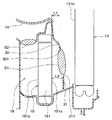
図1は、エンジンルームに配設されたコンプレッサおよびコンデンサ等から構成される冷凍サイクルを備えた車両用空調装置の一部を構成する室内ユニット部のうち、熱交換器部を収容している車両用空調ユニット10(以下、単に空調ユニット10と呼ぶ)の縦断面図である。なお、図1の各矢印DR1、DR2は、空調ユニット10が車両に搭載された車両搭載状態での向きを示す。すなわち、図1の両端矢印DR1は車両前後方向DR1を示し、両端矢印DR2は車両上下方向DR2を示している。
(First embodiment)
FIG. 1 shows a vehicle in which a heat exchanger part is housed among indoor unit parts constituting a part of a vehicle air conditioner provided with a refrigeration cycle including a compressor and a condenser disposed in an engine room. It is a longitudinal cross-sectional view of the air conditioning unit 10 (hereinafter, simply referred to as the air conditioning unit 10). In addition, each arrow DR1, DR2 of FIG. 1 shows the direction in the vehicle mounting state in which the
空調ユニット10は、車室内前部の不図示の計器盤内側において、車両左右方向すなわち車両幅方向の略中央部に配置される。車両用空調装置の上記室内ユニット部は、図1に示す空調ユニット10と、計器盤内側において助手席側にオフセット配置される図示しない送風機ユニットとに大別される。
The
この送風機ユニットは、周知のごとく、車室外空気である外気または車室内空気である内気を切替導入する内外気切替箱と、この内外気切替箱に導入された空気を送風する遠心式送風機とを備えている。この送風機ユニットの送風空気は、図1に示す空調ユニット10の空調ケース11内のうち、最前部の空気流入空間12に流入するようになっている。
As is well known, this blower unit includes an inside / outside air switching box for switching and introducing outside air as vehicle exterior air or inside air as vehicle interior air, and a centrifugal blower for blowing air introduced into the inside / outside air switch box. I have. The air blown from the blower unit flows into the
図1、図2に示すように、空調ユニット10は、空調ケース11、蒸発器13、エアミックスドア14、ヒータコア15、および吹出モードドア25などを備えている。空調ケース11は、車室内へ向かって流れる空気の通路を構成するもので、蒸発器13、エアミックスドア14、ヒータコア15、および吹出モードドア25を収容している。
As shown in FIGS. 1 and 2, the
空調ケース11は、ポリプロピレンのようなある程度の弾性を有し、機械的強度に優れた樹脂にて成形されている。空調ケース11は、成形上の型抜きの都合、および空調ケース11内への空調機器の組付上の理由等から、具体的には複数の分割ケースに分割して成形した後に、この複数の分割ケースを一体に締結する構成になっている。すなわち、空調ケース11は、複数のケース構成部材111が一体となって構成されている。
The
また、空調ケース11内には、空気流入空間12から空気が流れる複数の空気通路16、17、18が形成されている。詳細には、第1空気通路としての上流側通路16、第2空気通路としての冷風通路17、および、第3空気通路としての温風通路18が空調ケース11内に形成されている。上流側通路16は、冷風通路17および温風通路18に対して空気流れ上流側に配置され、空気流入空間12からの空気が流入する。
In the
冷風通路17は、上流側通路16を通過した空気である冷風を冷たいまま流すための空気通路であり、上流側通路16へ接続されている。冷風通路17には、その上流側通路16を通過した空気が上流側通路16から流入する。
The
温風通路18は、上流側通路16を通過した空気を加熱するための空気通路であり、冷風通路17と並列に上流側通路16へ接続されている。温風通路18には、上流側通路16を通過した空気が上流側通路16から流入する。そして、温風通路18は、冷風通路17と空気流れ下流側で合流している。
The
蒸発器13は、周知のように車両空調用冷凍サイクルの膨張弁等の減圧装置により減圧された低圧冷媒が流入し、この低圧冷媒が送風空気から吸熱して蒸発することにより、蒸発器13を通過する空気を冷却するようになっている。そして、蒸発器13は上流側通路16に配置されている。すなわち、蒸発器13は、上流側通路16を流れる送風空気を冷却する冷却器として機能し、冷風通路17と温風通路18との両方に対し空気流れ上流側に配置されている。
As is well known, the
蒸発器13は、空気が冷却されつつ通過する直方体状の冷却器コア部131を有し、その冷却器コア部131は、空気が流入する矩形状の冷却器空気流入面131aと、空気が流出する矩形状の冷却器空気流出面131bとを有している。
The
蒸発器13は、空調ユニット10の空調ケース11内において空気流入空間12の後方部に設けられ、冷却器空気流入面131aおよび冷却器空気流出面131bが車両上下方向DR2および車両幅方向(すなわち、車両前後方向DR1および車両上下方向DR2に直交する方向。図1、図2の紙面に対して垂直方向)に延びるように縦配置されている。
The
ヒータコア15は、周知のように、車両エンジンのエンジン冷却水である温水を熱源として、空気を加熱するものである。すなわち、ヒータコア15は、蒸発器13で冷却された空気を加熱する温水式の加熱器である。言い換えれば、ヒータコア15は温風通路18に配置され、その温風通路18を流れる空気を加熱する。
As is well known, the
ヒータコア15は、空気が加熱されつつ通過する直方体状の加熱器コア部151を有し、その加熱器コア部151は、空気が流入する矩形状の加熱器空気流入面151aと、空気が流出する矩形状の加熱器空気流出面151bとを有している。そして、ヒータコア15は、その加熱器空気流入面151aおよび加熱器空気流出面151bが車両上下方向DR2および車両幅方向に延びるように縦配置されている。
The
より詳細には、蒸発器13とヒータコア15は、冷却器空気流出面131bと加熱器空気流入面151aとが平行な状態で配置されるとともに、冷却器空気流出面131bにおける下方側の領域と加熱器空気流入面151aとが対向するように配置されている。なお、ここでいう「平行」は、実用上許容される誤差を含む略平行である。
More specifically, the
エアミックスドア14は、車両幅方向へ延びるドア軸心を中心として矢印MV1のように回動するロータリ式ドアであり、例えばアクチュエータ等により回動させられる。そして、エアミックスドア14はヒータコア15に対し空気流れ下流側に配置されている。
The
詳細に言えば、エアミックスドア14は、そのエアミックスドア14の回動位置に応じて、冷風通路17の開放度合を増減すると共に温風通路18の開放度合を増減する。すなわち、エアミックスドア14は、矢印a1のように冷風通路17を流れる空気の風量と、矢印a2のように温風通路18を流れる空気の風量との風量割合を調整して、車室内への吹出空気温度を調整する。
More specifically, the
具体的に、エアミックスドア14は、冷風通路17を全開状態にする一方で温風通路18を全閉状態にする最大冷房位置すなわちMAXCOOL位置から、冷風通路17を全閉状態にする一方で温風通路18を全開状態にする最大暖房位置すなわちMAXHOT位置までの範囲で回動する。従って、エアミックスドア14は、ヒータコア15に対する空気流れ下流側にて温風通路18を開閉する開閉装置として機能すると共に、冷風通路17を開閉する開閉装置としても機能する。図1では、最大冷房位置にあるエアミックスドア14が図示されている。
Specifically, the
空調ケース11の上面部のうち車両前方側部位にデフロスタ開口部20が開口しており、空調ケース11の上面部のうちデフロスタ開口部20に対する車両後方側部位にフェイス開口部21が開口している。また、フット開口部22はフェイス開口部21よりも車両後方側に設けられている。
A
デフロスタ開口部20は、冷風通路17および温風通路18からの空気が互いに合流して成る空調空気を車両前面ガラス内面に向けて吹き出すための開口部である。フェイス開口部21は、その空調空気を乗員の頭胸部に向かって吹き出すための開口部である。また、フット開口部22は、その空調空気を車室内の乗員の足元部に向けて吹き出すための開口部である。
The
吹出モードドア25は、エアミックスドア14と共通のドア軸心を中心として矢印MV2のように回動するロータリ式ドアであり、例えばサーボモータ等のアクチュエータにより回動させられる。そして、吹出モードドア25は、その吹出モードドア25の回動位置に応じて、デフロスタ開口部20とフェイス開口部21とフット開口部22とを選択的に開閉する。なお、吹出モードドア25はエアミックスドア14とは別個に作動する。
The blow-out
吹出モードドア25は、吹出口モードをフェイスモード、バイレベルモード、フットモード、フットデフロスタモードまたはデフロスタモードのいずれに切り替えることが可能となっている。図1では、吹出口モードがフェイスモードとなっているときの吹出モードドア25が図示されている。
The
上述したように、温風通路18はヒータコア15に対する空気流れ下流側にてエアミックスドア14により開閉されるので、温風通路18においてその開閉される側とは逆側であるヒータコア15に対する空気流れ上流側は常に開放されたままとなっている。
As described above, since the
そして、本実施形態では、ヒータコア15に対する空気流れ上流側に、加熱器空気流入面151aの一部を覆うようにして板状の第1ガイド部材30と板状の第2ガイド部材31とが配置されている。なお、第1ガイド部材30と第2ガイド部材31は、本発明のガイド部材を構成している。
In the present embodiment, the plate-like
より詳細には、第1ガイド部材30は、加熱器空気流入面151aにおける冷風通路17に近い側の部位の車両幅方向全域を覆うように配置されている。第2ガイド部材31は、加熱器空気流入面151aにおける冷風通路17から遠い側の部位の車両幅方向全域を覆うように配置されている。
In more detail, the
加熱器空気流入面151aにおける第1ガイド部材30および第2ガイド部材31にて覆われていない部位の開口面積S1は、温風通路18におけるヒータコア15よりも空気流れ下流側の部位の最小通路面積S2よりも大きくなっている。
The opening area S1 of the portion not covered with the
第1ガイド部材30は、空調ケース11と一体成形されている。また、第1ガイド部材30は、車両幅方向に沿って見たときに蒸発器13側に向かって凸となる円弧状になっている。
The
第1ガイド部材30と加熱器空気流入面151aとの間の隙間は、第2ガイド部材31に近い側の隙間が第2ガイド部材31から遠い側の隙間よりも大きくなっている。
In the gap between the
第2ガイド部材31は、空調ケース11と一体成形されている。また、第2ガイド部材31は、加熱器空気流入面151aと平行な平板になっている。
The
第1ガイド部材30における第2ガイド部材31側の端部301と加熱器空気流入面151aとの距離L1は、第2ガイド部材31における第1ガイド部材30側の端部311と加熱器空気流入面151aとの距離L2よりも短くなっている。
The distance L1 between the
ここで、図3に基づいて、第1ガイド部材30および第2ガイド部材31を備えていない従来の空調ユニットにおける再熱発生メカニズムについて説明する。
エアミックスドア14により温風通路18が全閉された状態のとき(すなわち、最大冷房時)には、蒸発器13を通過する冷風である空気は、矢印a3に示すように冷風通路17へと流れる。このとき、蒸発器13から吹き出た空気の一部は、温風通路18側に進入して加熱器空気流入面151aを舐めるように流れて加熱されてしまう。
Here, based on FIG. 3, the reheat generation mechanism in the conventional air conditioning unit which is not provided with the
When the
また、蒸発器13から吹き出た空気の一部は、矢印a5に示すように、加熱器空気流入面151aから加熱器空気流出面151bに向かって加熱器コア部151内を流れた後、加熱器空気流出面151bから加熱器空気流入面151aに向かって加熱器コア部151内を流れて加熱され、この加熱された空気が冷風通路17へ流れる主流に合流して冷風通路17へと流れる。
Further, as shown by an arrow a5, a part of the air blown out from the
これらにより、空気が加熱される再熱という問題が生じる。 As a result, there arises a problem of reheating in which air is heated.
これに対し、本実施形態では、エアミックスドア14により温風通路18が全閉された状態のときに蒸発器13を通過した空気は、第1ガイド部材30および第2ガイド部材31により温風通路18側への進入等が抑制されて、ヒータコア15による再熱が低減される。
On the other hand, in this embodiment, the air that has passed through the
具体的には、蒸発器13を通過した空気は、第2ガイド部材31に衝突して冷風通路17側に流れの向きが変えられるため、温風通路18側への進入が抑制される。
Specifically, since the air that has passed through the
また、第1ガイド部材30および第2ガイド部材31を備えている場合、温風通路18側に進入した空気の一部は、矢印a4に示すように、加熱器コア部151内を流れる循環流となり、この循環流a4の空気も加熱されてしまう。因みに、この循環流a4は、蒸発器13から吹き出て冷風通路17へ流れる主流の粘性で駆動されて発生する。
In addition, when the
この循環流a4と冷風通路17へ流れる主流との接触により熱交換が行われるが、循環流a4と主流との接触による熱交換の場合は、従来のように加熱器コア部151で加熱された空気が冷風通路17へ流れる主流に合流する場合よりも、再熱の度合いは小さくなる。
Heat exchange is performed by contact between the circulation flow a4 and the main flow flowing into the
そして、それらが相俟って、ヒータコア15による再熱が低減される。因みに、第1ガイド部材30および第2ガイド部材31を備える空調ユニット10と、第1ガイド部材30および第2ガイド部材31を備えていない空調ユニットとを用意し、エアミックスドア14により温風通路18が全閉された状態のときの吹き出し空気温度を実測したところ、再熱による吹き出し空気温度の上昇量は、第1ガイド部材30および第2ガイド部材31を備える空調ユニット10の方が、第1ガイド部材30および第2ガイド部材31を備えていない空調ユニットよりも、1.5℃低くなることが確認された。
And together, they reduce reheating by the
また、加熱器空気流入面151aにおける第1ガイド部材30および第2ガイド部材31にて覆われていない部位の開口面積S1を、温風通路18におけるヒータコア15よりも空気流れ下流側の部位の最小通路面積S2よりも大きくしているため、エアミックスドア14により温風通路18が全開された状態のとき(すなわち、最大暖房時)の通風抵抗増加を防止することができる。
Further, the opening area S1 of the portion that is not covered by the
また、第1ガイド部材30を、車両幅方向に沿って見たときに蒸発器13側に向かって凸となる円弧状にしているため、蒸発器13から吹き出て冷風通路17へと流れる主流が第1ガイド部材30近傍を通過する際の通風抵抗増加を防止することができる。
Further, since the
また、第1ガイド部材30と加熱器空気流入面151aとの間の隙間を、第2ガイド部材31に近い側の隙間が第2ガイド部材31から遠い側の隙間よりも大きくなるようにしているため、エアミックスドア14により温風通路18が開かれた状態のときに、加熱器空気流入面151aにおける第1ガイド部材30にて覆われている部位に、空気をスムーズに流入させることができる。
Further, the gap between the
また、第1ガイド部材30における第2ガイド部材31側の端部301と加熱器空気流入面151aとの距離L1を、第2ガイド部材31における第1ガイド部材30側の端部311と加熱器空気流入面151aとの距離L2よりも短くしている。このため、エアミックスドア14により温風通路18が全閉された状態のときに、第2ガイド部材31に衝突して冷風通路17側に流れの向きが変えられた空気は、第1ガイド部材30よりも蒸発器13側の空間を通過しやすく、第1ガイド部材30よりも加熱器空気流入面151a側の空間には流入しにくい。
Further, the distance L1 between the
以上述べたように、本実施形態によると、第1ガイド部材30および第2ガイド部材31を設けるという簡単な構造で、ヒータコア15による再熱を低減することができる。
As described above, according to this embodiment, reheating by the
(第2実施形態)
本発明の第2実施形態について説明する。以下、第1実施形態と異なる部分についてのみ説明する。
(Second Embodiment)
A second embodiment of the present invention will be described. Only the parts different from the first embodiment will be described below.
なお、図4、5の各矢印DR1、DR2、DR3は、空調ユニット10が車両に搭載された車両搭載状態での向きを示す。このうち、図5の両端矢印DR3は車両左右方向(すなわち車両幅方向)DR3を示している。また、図6は従来の空調ユニットを示すものであって、第2実施形態の図5に相当する図である。
In addition, each arrow DR1, DR2, DR3 of FIG. 4, 5 shows the direction in the vehicle mounting state in which the
図4、5に示すように、本実施形態ではヒータコア15の配置が第1実施形態と異なっている。具体的には、第1実施形態のヒータコア15は縦配置であるが、本実施形態のヒータコア15は、その加熱器空気流入面151aおよび加熱器空気流出面151bが車両の水平方向へ二次元的に延びるように、横配置されている。
As shown in FIGS. 4 and 5, in the present embodiment, the arrangement of the
より詳細には、蒸発器13とヒータコア15は、冷却器空気流出面131bと加熱器空気流入面151aとが直交状態で配置されている。なお、ここでいう「直交」は、実用上許容される誤差を含む略直交である。
More specifically, in the
また、加熱器空気流入面151aが下方で加熱器空気流出面151bが上方に位置しており、加熱器空気流入面151aと空調ケース11の底部内壁面との間に、温風通路18の一部である加熱器空気流入通路181が形成されている。そして、エアミックスドア14により温風通路18が開かれた状態のときには、蒸発器13から吹き出た空気は、加熱器空気流入通路181を通って加熱器コア部151に流入するようになっている。なお、空調ケース11の底部内壁面は、本発明の空調ケースにおける加熱器空気流入面に対向する部位に相当する。
Further, the heater
加熱器コア部151は、温水を流通させるチューブ152が多数積層されて構成され、チューブ152の長手方向が車両前後方向DR1と一致している。
The
ヒータコア15に対する空気流れ上流側に位置する加熱器空気流入通路181には、加熱器空気流入通路181を複数個に分割する板状のガイド部材32が配置されている。
A plate-shaped
ガイド部材32は、空調ケース11と一体成形されており、空調ケース11の底部内壁面から上方に向かって延びるとともに、車両前後方向DR1に延びている。
The
ガイド部材32は、本実施形態では2個設けられており、これにより加熱器空気流入通路181は3個の空間に細分化されている。
In this embodiment, two
ガイド部材32は、車両上下方向DR2に沿って見たときに、換言すると、加熱器空気流入面151aと加熱器空気流出面151bの並び方向に沿って見たときに、加熱器コア部151のチューブ152と重なる位置に配置されている。
When viewed along the vehicle vertical direction DR2, in other words, when the
ここで、図6に基づいて、ガイド部材32を備えていない従来の空調ユニットにおける再熱発生メカニズムについて説明する。
Here, based on FIG. 6, the reheat generation mechanism in the conventional air-conditioning unit which is not provided with the
エアミックスドアにより温風通路が全閉された状態のときには、図6に示すように、蒸発器13を通過する冷風である空気は、冷風通路17へと流れるとともに、一部は加熱器空気流入通路181に進入する。
When the hot air passage is fully closed by the air mix door, as shown in FIG. 6, the air that is the cold air passing through the
加熱器空気流入通路181に進入した空気は、矢印a7に示すように、蒸発器13下流側の圧力差により加熱器空気流入通路181内でUターン流となる。そして、このUターン流の空気は、加熱器空気流入面151aを舐めるように流れて加熱されてしまう。
The air that has entered the heater
これに対し、本実施形態では、エアミックスドア14により温風通路18が全閉された状態のときに加熱器空気流入通路181に進入した空気は、矢印a6に示すように、ガイド部材32にて細分化された各々の加熱器空気流入通路181内でUターン流となる。
On the other hand, in the present embodiment, the air that has entered the heater
このように、細分化された各々の加熱器空気流入通路181はUターン流に対して通風抵抗が大きくなるため、Uターン流が抑制され、加熱器空気流入通路181への空気の進入が抑制される。その結果、Uターン流の合計空気量は従来の空調ユニットにおけるUターン流の空気量よりも少なくなり、Uターン流の空気が加熱器コア部151表面から拾う熱が減り、ヒータコア15による再熱が低減される。
As described above, since each of the subdivided heater
因みに、ガイド部材32を備える空調ユニット10と、ガイド部材32を備えていない空調ユニットとを用意し、エアミックスドア14により温風通路18が全閉された状態のときの吹き出し空気温度を実測したところ、再熱による吹き出し空気温度の上昇量は、ガイド部材32を備える空調ユニット10の方が、ガイド部材32を備えていない空調ユニットよりも、0.5℃程度低くなることが確認された。
Incidentally, the
また、ガイド部材32を、車両上下方向DR2に沿って見たときに加熱器コア部151のチューブ152と重なる位置に配置しているため、エアミックスドア14により温風通路18が全開された状態のとき(すなわち、最大暖房時)の空気流に対してガイド部材32は通風抵抗とならない。
Further, since the
以上述べたように、本実施形態によると、ガイド部材32を設けるという簡単な構造で、ヒータコア15による再熱を低減することができる。
As described above, according to this embodiment, reheating by the
(他の実施形態)
(1)上述の各実施形態において、エアミックスドア14は、ヒータコア15に対する空気流れ下流側にて温風通路18を開閉するが、逆に、ヒータコア15に対する空気流れ上流側にて温風通路18を開閉しても差し支えない。但し、温風通路18がヒータコア15に対する空気流れ上流側にて開閉される場合には、第1ガイド部材30、第2ガイド部材31、およびガイド部材32は、ヒータコア15に対する空気流れ下流側に設けられる。要するに、エアミックスドア14は、ヒータコア15に対する空気流れ上流側と空気流れ下流側との一方にて温風通路18を開閉し、それと共に、第1ガイド部材30、第2ガイド部材31、およびガイド部材32は、ヒータコア15に対する空気流れ上流側と空気流れ下流側との他方に設けられればよい。
(Other embodiments)
(1) In each of the above-described embodiments, the
(2)上述の各実施形態において、空調ケース11は、複数のケース構成部材111が一体となって構成されているが、単一のケース構成部材111で構成されていてもよい。
(2) In each of the above-described embodiments, the
(3)上述の各実施形態において、第1ガイド部材30、第2ガイド部材31、およびガイド部材32は、空調ケース11と一体成形されているが、第1ガイド部材30、第2ガイド部材31、およびガイド部材32は、空調ケース11とは別に加工した後、空調ケース11に接合してもよい。
(3) In each above-mentioned embodiment, although the
(4)上述の各実施形態において、エアミックスドア14は、温風通路18を開閉すると共に、冷風通路17も開閉するが、冷風通路17を開閉する機能を備えていなくても差し支えない。例えば、エアミックスドア14とは別の開閉装置で冷風通路17が開閉されてもよい。
(4) In each of the above-described embodiments, the
(5)上述の各実施形態において、エアミックスドア14および吹出モードドア25は何れもロータリ式ドアであるが、そのドア形式に限定はない。例えばエアミックスドア14および吹出モードドア25は平板形状のドアであっても差し支えない。
(5) In each of the embodiments described above, the
なお、本発明は上記した実施形態に限定されるものではなく、特許請求の範囲に記載した範囲内において適宜変更が可能である。また、上記各実施形態は、互いに無関係なものではなく、組み合わせが明らかに不可な場合を除き、適宜組み合わせが可能である。 In addition, this invention is not limited to above-described embodiment, In the range described in the claim, it can change suitably. Further, the above embodiments are not irrelevant to each other, and can be combined as appropriate unless the combination is clearly impossible.
また、上記各実施形態において、実施形態を構成する要素は、特に必須であると明示した場合および原理的に明らかに必須であると考えられる場合等を除き、必ずしも必須のものではないことは言うまでもない。 In each of the above-described embodiments, it is needless to say that elements constituting the embodiment are not necessarily indispensable except for the case where it is clearly indicated that the element is essential and the case where the element is clearly considered essential in principle. Yes.
また、上記各実施形態において、実施形態の構成要素の個数、数値、量、範囲等の数値が言及されている場合、特に必須であると明示した場合および原理的に明らかに特定の数に限定される場合等を除き、その特定の数に限定されるものではない。 Further, in each of the above embodiments, when numerical values such as the number, numerical value, quantity, range, etc. of the constituent elements of the embodiment are mentioned, it is clearly limited to a specific number when clearly indicated as essential and in principle. The number is not limited to the specific number except for the case.
また、上記各実施形態において、構成要素等の材質、形状、位置関係等に言及するときは、特に明示した場合および原理的に特定の材質、形状、位置関係等に限定される場合等を除き、その材質、形状、位置関係等に限定されるものではない。 In each of the above embodiments, when referring to the material, shape, positional relationship, etc. of the constituent elements, etc., unless otherwise specified, or in principle limited to a specific material, shape, positional relationship, etc. The material, shape, positional relationship, etc. are not limited.
11 空調ケース
14 エアミックスドア(開閉装置)
15 ヒータコア(加熱器)
16 上流側通路(第1空気通路)
17 冷風通路(第2空気通路)
18 第3温風通路(空気通路)
30 第1ガイド部材(ガイド部材)
31 第2ガイド部材(ガイド部材)
32 ガイド部材
151a 加熱器空気流入面
151b 加熱器空気流出面
11 Air-
15 Heater core (heater)
16 Upstream passage (first air passage)
17 Cold air passage (second air passage)
18 3rd hot air passage (air passage)
30 1st guide member (guide member)
31 Second guide member (guide member)
32
Claims (3)
前記第3空気通路に配置され、前記空気が流入する加熱器空気流入面(151a)および前記空気が流出する加熱器空気流出面(151b)を有して前記第3空気通路を流れる前記空気を加熱する加熱器(15)と、
前記加熱器に対する空気流れ下流側に配置されて前記第3空気通路を開閉する開閉装置(14)と、
前記加熱器に対する空気流れ上流側に配置され、前記第3空気通路が前記開閉装置により閉じられた状態のときに前記第1空気通路から前記第2空気通路に流れる前記空気が、前記第3空気通路側に進入することを抑制する板状のガイド部材(32)と、
前記第1空気通路に配置され、前記空気が流入する冷却器空気流入面(131a)および前記空気が流出する冷却器空気流出面(131b)を有して前記第1空気通路を流れる前記空気を冷却する冷却器(13)と、を備え、
前記加熱器と前記冷却器は、前記加熱器空気流入面と前記冷却器空気流出面とが直交するように配置され、
前記ガイド部材は、前記空調ケースにおける前記加熱器空気流入面に対向する部位と前記加熱器空気流入面との間に形成された加熱器空気流入通路(181)に配置されるとともに、前記加熱器空気流入通路を複数個に分割するように構成されていることを特徴とする車両用空調ユニット。 A first air passage (16) through which air flows, a second air passage (17) connected to the first air passage and into which the air flows from the first air passage, and the second air passage to the first air passage. An air conditioning case (11) connected in parallel with an air passage and formed with a third air passage (18) where the air flows in from the first air passage and merges with the second air passage on the downstream side of the air flow. When,
The air flowing in the third air passage having a heater air inflow surface (151a) through which the air flows and a heater air outflow surface (151b) through which the air flows out are disposed in the third air passage. A heater (15) for heating;
A switchgear (14) for opening and closing said third air passage are arranged in the air flow downstream side against the heater,
The air that is arranged on the upstream side of the air flow with respect to the heater and that flows from the first air passage to the second air passage when the third air passage is closed by the switchgear is the third air. A plate-like guide member ( 32) for suppressing entry into the passage side ;
The air flowing through the first air passage having a cooler air inflow surface (131a) through which the air flows and a cooler air outflow surface (131b) through which the air flows out are disposed in the first air passage. A cooler (13) for cooling,
The heater and the cooler are arranged such that the heater air inflow surface and the cooler air outflow surface are orthogonal to each other,
The guide member is disposed in a heater air inflow passage (181) formed between a portion of the air conditioning case facing the heater air inflow surface and the heater air inflow surface, and the heater A vehicle air-conditioning unit configured to divide an air inflow passage into a plurality of parts.
前記第3空気通路に配置され、前記空気が流入する加熱器空気流入面(151a)および前記空気が流出する加熱器空気流出面(151b)を有して前記第3空気通路を流れる前記空気を加熱する加熱器(15)と、 The air flowing in the third air passage having a heater air inflow surface (151a) through which the air flows and a heater air outflow surface (151b) through which the air flows out are disposed in the third air passage. A heater (15) for heating;
前記加熱器に対する空気流れ下流側に配置されて前記第3空気通路を開閉する開閉装置(14)と、 An opening and closing device (14) disposed on the downstream side of the air flow with respect to the heater to open and close the third air passage;
前記加熱器に対する空気流れ上流側に配置され、前記第3空気通路が前記開閉装置により閉じられた状態のときに前記第1空気通路から前記第2空気通路に流れる前記空気が、前記第3空気通路側に進入することを抑制する板状のガイド部材(32)と、 The air that is arranged on the upstream side of the air flow with respect to the heater and that flows from the first air passage to the second air passage when the third air passage is closed by the switchgear is the third air. A plate-like guide member (32) for suppressing entry into the passage side;
前記第1空気通路に配置され、前記空気が流入する冷却器空気流入面(131a)および前記空気が流出する冷却器空気流出面(131b)を有して前記第1空気通路を流れる前記空気を冷却する冷却器(13)と、を備え、 The air flowing through the first air passage having a cooler air inflow surface (131a) through which the air flows and a cooler air outflow surface (131b) through which the air flows out are disposed in the first air passage. A cooler (13) for cooling,
前記加熱器と前記冷却器は、前記加熱器空気流入面と前記冷却器空気流出面とが直交するように配置され、 The heater and the cooler are arranged such that the heater air inflow surface and the cooler air outflow surface are orthogonal to each other,
前記加熱器は、前記空気と熱交換する流体を流通させるチューブ(152)が多数積層されて構成され、前記ガイド部材は、前記加熱器空気流入面と前記加熱器空気流出面の並び方向に沿って見たときに、前記チューブと重なる位置に配置されていることを特徴とする車両用空調ユニット。 The heater is configured by laminating a plurality of tubes (152) through which a fluid that exchanges heat with the air flows, and the guide member is arranged along an arrangement direction of the heater air inflow surface and the heater air outflow surface. The vehicle air conditioning unit is disposed at a position overlapping the tube when viewed from above.
Priority Applications (4)
| Application Number | Priority Date | Filing Date | Title |
|---|---|---|---|
| JP2014246954A JP6372330B2 (en) | 2014-12-05 | 2014-12-05 | Air conditioning unit for vehicles |
| BR112017011310-4A BR112017011310B1 (en) | 2014-12-05 | 2015-11-26 | AIR CONDITIONING UNIT FOR A VEHICLE. |
| CN201580065497.8A CN107000539B (en) | 2014-12-05 | 2015-11-26 | Vehicular air-conditioning unit |
| PCT/JP2015/005868 WO2016088338A1 (en) | 2014-12-05 | 2015-11-26 | Vehicular air-conditioning unit |
Applications Claiming Priority (1)
| Application Number | Priority Date | Filing Date | Title |
|---|---|---|---|
| JP2014246954A JP6372330B2 (en) | 2014-12-05 | 2014-12-05 | Air conditioning unit for vehicles |
Publications (3)
| Publication Number | Publication Date |
|---|---|
| JP2016107799A JP2016107799A (en) | 2016-06-20 |
| JP2016107799A5 JP2016107799A5 (en) | 2017-03-16 |
| JP6372330B2 true JP6372330B2 (en) | 2018-08-15 |
Family
ID=56091301
Family Applications (1)
| Application Number | Title | Priority Date | Filing Date |
|---|---|---|---|
| JP2014246954A Active JP6372330B2 (en) | 2014-12-05 | 2014-12-05 | Air conditioning unit for vehicles |
Country Status (4)
| Country | Link |
|---|---|
| JP (1) | JP6372330B2 (en) |
| CN (1) | CN107000539B (en) |
| BR (1) | BR112017011310B1 (en) |
| WO (1) | WO2016088338A1 (en) |
Families Citing this family (1)
| Publication number | Priority date | Publication date | Assignee | Title |
|---|---|---|---|---|
| FR3082605A1 (en) * | 2018-06-13 | 2019-12-20 | Valeo Systemes Thermiques | HEATING VENTILATION AND AIR CONDITIONING SYSTEM |
Family Cites Families (7)
| Publication number | Priority date | Publication date | Assignee | Title |
|---|---|---|---|---|
| JP2000071753A (en) * | 1998-08-31 | 2000-03-07 | Denso Corp | Air cooling apparatus for vehicle |
| JP2003034114A (en) * | 2001-07-19 | 2003-02-04 | Zexel Valeo Climate Control Corp | Air-conditioning device for vehicle |
| EP1641643B1 (en) * | 2003-06-30 | 2008-01-16 | Behr GmbH & Co. KG | Air-conditioning system for vehicles |
| JP5127157B2 (en) * | 2006-05-18 | 2013-01-23 | 株式会社日本クライメイトシステムズ | Air conditioner for vehicles |
| JP5127204B2 (en) * | 2006-11-20 | 2013-01-23 | 株式会社日本クライメイトシステムズ | Air conditioner for vehicles |
| JP2012224112A (en) * | 2011-04-15 | 2012-11-15 | Valeo Japan Co Ltd | Air conditioner for vehicle |
| JP5545267B2 (en) * | 2011-05-17 | 2014-07-09 | 株式会社デンソー | Air conditioner for vehicles |
-
2014
- 2014-12-05 JP JP2014246954A patent/JP6372330B2/en active Active
-
2015
- 2015-11-26 WO PCT/JP2015/005868 patent/WO2016088338A1/en active Application Filing
- 2015-11-26 CN CN201580065497.8A patent/CN107000539B/en active Active
- 2015-11-26 BR BR112017011310-4A patent/BR112017011310B1/en active IP Right Grant
Also Published As
| Publication number | Publication date |
|---|---|
| CN107000539B (en) | 2019-03-29 |
| CN107000539A (en) | 2017-08-01 |
| BR112017011310A2 (en) | 2018-01-02 |
| BR112017011310B1 (en) | 2022-09-06 |
| WO2016088338A1 (en) | 2016-06-09 |
| JP2016107799A (en) | 2016-06-20 |
Similar Documents
| Publication | Publication Date | Title |
|---|---|---|
| JP5569513B2 (en) | Air conditioner for vehicles | |
| JP4444347B2 (en) | Air conditioner for vehicles | |
| JP4811385B2 (en) | Air conditioner for vehicles | |
| JP6221890B2 (en) | Air conditioning unit for vehicles | |
| CN107000538B (en) | Air conditioning unit for vehicle | |
| JP2010018248A (en) | Air conditioner for vehicle | |
| JP6269432B2 (en) | Air conditioner for vehicles | |
| JP6372330B2 (en) | Air conditioning unit for vehicles | |
| JP4985604B2 (en) | Air conditioner for vehicles | |
| JP2006001378A (en) | Air conditioner for vehicle | |
| JP5962499B2 (en) | In-vehicle air conditioner | |
| JP2005306166A (en) | Air-conditioner for vehicle | |
| JP5532545B2 (en) | Air conditioner | |
| JP2008265447A (en) | Vehicular air-conditioner | |
| WO2017065101A1 (en) | Air-conditioning unit for vehicles | |
| JP4624773B2 (en) | Air conditioner for vehicles | |
| JP2009018644A (en) | Vehicle air conditioner | |
| JP4645537B2 (en) | Air conditioner for vehicles | |
| JP2009006896A (en) | Vehicle air-conditioner | |
| JP2011207278A (en) | Air conditioning case | |
| JP2006224734A (en) | Vehicular air conditioner | |
| JP5556757B2 (en) | Air conditioner for vehicles | |
| WO2016031136A1 (en) | Vehicle air conditioning unit | |
| JP2011207279A (en) | Air conditioning case | |
| JP2009196507A (en) | Air-conditioning device for vehicle |
Legal Events
| Date | Code | Title | Description |
|---|---|---|---|
| A521 | Request for written amendment filed |
Free format text: JAPANESE INTERMEDIATE CODE: A523 Effective date: 20170207 |
|
| A621 | Written request for application examination |
Free format text: JAPANESE INTERMEDIATE CODE: A621 Effective date: 20170629 |
|
| TRDD | Decision of grant or rejection written | ||
| A01 | Written decision to grant a patent or to grant a registration (utility model) |
Free format text: JAPANESE INTERMEDIATE CODE: A01 Effective date: 20180619 |
|
| A61 | First payment of annual fees (during grant procedure) |
Free format text: JAPANESE INTERMEDIATE CODE: A61 Effective date: 20180702 |
|
| R151 | Written notification of patent or utility model registration |
Ref document number: 6372330 Country of ref document: JP Free format text: JAPANESE INTERMEDIATE CODE: R151 |
|
| R250 | Receipt of annual fees |
Free format text: JAPANESE INTERMEDIATE CODE: R250 |
|
| R250 | Receipt of annual fees |
Free format text: JAPANESE INTERMEDIATE CODE: R250 |
|
| R250 | Receipt of annual fees |
Free format text: JAPANESE INTERMEDIATE CODE: R250 |