WO2021060402A1 - ヘッドアップディスプレイ用プロジェクター - Google Patents
ヘッドアップディスプレイ用プロジェクター Download PDFInfo
- Publication number
- WO2021060402A1 WO2021060402A1 PCT/JP2020/036115 JP2020036115W WO2021060402A1 WO 2021060402 A1 WO2021060402 A1 WO 2021060402A1 JP 2020036115 W JP2020036115 W JP 2020036115W WO 2021060402 A1 WO2021060402 A1 WO 2021060402A1
- Authority
- WO
- WIPO (PCT)
- Prior art keywords
- layer
- liquid crystal
- light
- cholesteric liquid
- projector
- Prior art date
Links
Images


Classifications
-
- G—PHYSICS
- G03—PHOTOGRAPHY; CINEMATOGRAPHY; ANALOGOUS TECHNIQUES USING WAVES OTHER THAN OPTICAL WAVES; ELECTROGRAPHY; HOLOGRAPHY
- G03B—APPARATUS OR ARRANGEMENTS FOR TAKING PHOTOGRAPHS OR FOR PROJECTING OR VIEWING THEM; APPARATUS OR ARRANGEMENTS EMPLOYING ANALOGOUS TECHNIQUES USING WAVES OTHER THAN OPTICAL WAVES; ACCESSORIES THEREFOR
- G03B21/00—Projectors or projection-type viewers; Accessories therefor
- G03B21/54—Accessories
- G03B21/56—Projection screens
- G03B21/60—Projection screens characterised by the nature of the surface
- G03B21/62—Translucent screens
-
- G—PHYSICS
- G02—OPTICS
- G02B—OPTICAL ELEMENTS, SYSTEMS OR APPARATUS
- G02B27/00—Optical systems or apparatus not provided for by any of the groups G02B1/00 - G02B26/00, G02B30/00
- G02B27/01—Head-up displays
- G02B27/0101—Head-up displays characterised by optical features
-
- G—PHYSICS
- G02—OPTICS
- G02B—OPTICAL ELEMENTS, SYSTEMS OR APPARATUS
- G02B27/00—Optical systems or apparatus not provided for by any of the groups G02B1/00 - G02B26/00, G02B30/00
- G02B27/28—Optical systems or apparatus not provided for by any of the groups G02B1/00 - G02B26/00, G02B30/00 for polarising
- G02B27/286—Optical systems or apparatus not provided for by any of the groups G02B1/00 - G02B26/00, G02B30/00 for polarising for controlling or changing the state of polarisation, e.g. transforming one polarisation state into another
-
- G—PHYSICS
- G02—OPTICS
- G02B—OPTICAL ELEMENTS, SYSTEMS OR APPARATUS
- G02B5/00—Optical elements other than lenses
- G02B5/20—Filters
- G02B5/26—Reflecting filters
-
- G—PHYSICS
- G02—OPTICS
- G02B—OPTICAL ELEMENTS, SYSTEMS OR APPARATUS
- G02B5/00—Optical elements other than lenses
- G02B5/30—Polarising elements
- G02B5/3016—Polarising elements involving passive liquid crystal elements
-
- G—PHYSICS
- G02—OPTICS
- G02B—OPTICAL ELEMENTS, SYSTEMS OR APPARATUS
- G02B5/00—Optical elements other than lenses
- G02B5/30—Polarising elements
- G02B5/3025—Polarisers, i.e. arrangements capable of producing a definite output polarisation state from an unpolarised input state
-
- G—PHYSICS
- G02—OPTICS
- G02F—OPTICAL DEVICES OR ARRANGEMENTS FOR THE CONTROL OF LIGHT BY MODIFICATION OF THE OPTICAL PROPERTIES OF THE MEDIA OF THE ELEMENTS INVOLVED THEREIN; NON-LINEAR OPTICS; FREQUENCY-CHANGING OF LIGHT; OPTICAL LOGIC ELEMENTS; OPTICAL ANALOGUE/DIGITAL CONVERTERS
- G02F1/00—Devices or arrangements for the control of the intensity, colour, phase, polarisation or direction of light arriving from an independent light source, e.g. switching, gating or modulating; Non-linear optics
- G02F1/01—Devices or arrangements for the control of the intensity, colour, phase, polarisation or direction of light arriving from an independent light source, e.g. switching, gating or modulating; Non-linear optics for the control of the intensity, phase, polarisation or colour
- G02F1/13—Devices or arrangements for the control of the intensity, colour, phase, polarisation or direction of light arriving from an independent light source, e.g. switching, gating or modulating; Non-linear optics for the control of the intensity, phase, polarisation or colour based on liquid crystals, e.g. single liquid crystal display cells
- G02F1/137—Devices or arrangements for the control of the intensity, colour, phase, polarisation or direction of light arriving from an independent light source, e.g. switching, gating or modulating; Non-linear optics for the control of the intensity, phase, polarisation or colour based on liquid crystals, e.g. single liquid crystal display cells characterised by the electro-optical or magneto-optical effect, e.g. field-induced phase transition, orientation effect, guest-host interaction or dynamic scattering
- G02F1/13718—Devices or arrangements for the control of the intensity, colour, phase, polarisation or direction of light arriving from an independent light source, e.g. switching, gating or modulating; Non-linear optics for the control of the intensity, phase, polarisation or colour based on liquid crystals, e.g. single liquid crystal display cells characterised by the electro-optical or magneto-optical effect, e.g. field-induced phase transition, orientation effect, guest-host interaction or dynamic scattering based on a change of the texture state of a cholesteric liquid crystal
-
- G—PHYSICS
- G02—OPTICS
- G02B—OPTICAL ELEMENTS, SYSTEMS OR APPARATUS
- G02B27/00—Optical systems or apparatus not provided for by any of the groups G02B1/00 - G02B26/00, G02B30/00
- G02B27/01—Head-up displays
- G02B27/0101—Head-up displays characterised by optical features
- G02B2027/0112—Head-up displays characterised by optical features comprising device for genereting colour display
-
- G—PHYSICS
- G02—OPTICS
- G02B—OPTICAL ELEMENTS, SYSTEMS OR APPARATUS
- G02B27/00—Optical systems or apparatus not provided for by any of the groups G02B1/00 - G02B26/00, G02B30/00
- G02B27/01—Head-up displays
- G02B27/0101—Head-up displays characterised by optical features
- G02B2027/0118—Head-up displays characterised by optical features comprising devices for improving the contrast of the display / brillance control visibility
-
- G—PHYSICS
- G02—OPTICS
- G02B—OPTICAL ELEMENTS, SYSTEMS OR APPARATUS
- G02B27/00—Optical systems or apparatus not provided for by any of the groups G02B1/00 - G02B26/00, G02B30/00
- G02B27/01—Head-up displays
- G02B27/0101—Head-up displays characterised by optical features
- G02B2027/0145—Head-up displays characterised by optical features creating an intermediate image
-
- G—PHYSICS
- G03—PHOTOGRAPHY; CINEMATOGRAPHY; ANALOGOUS TECHNIQUES USING WAVES OTHER THAN OPTICAL WAVES; ELECTROGRAPHY; HOLOGRAPHY
- G03B—APPARATUS OR ARRANGEMENTS FOR TAKING PHOTOGRAPHS OR FOR PROJECTING OR VIEWING THEM; APPARATUS OR ARRANGEMENTS EMPLOYING ANALOGOUS TECHNIQUES USING WAVES OTHER THAN OPTICAL WAVES; ACCESSORIES THEREFOR
- G03B21/00—Projectors or projection-type viewers; Accessories therefor
- G03B21/14—Details
- G03B21/28—Reflectors in projection beam
Definitions
- the present invention relates to a projector used for a head-up display.
- head-up display head-up display system
- head-up display head-up display system
- the head-up display is also referred to as "HUD”.
- HUD is an abbreviation for "Head up Display”.
- the driver can obtain various information such as a map, running speed, and vehicle condition while looking at the outside world in front of him without moving his eyes significantly. However, it can be expected to drive more safely.
- the projected light projected by the projector is transmitted through the transmission window provided on the dashboard and projected onto the windshield glass (combiner) with a built-in half mirror to display the image on the windshield glass.
- the windshield glass combiner
- External light entering from the outside is known as one of the causes of deterioration of the projector constituting the HUD.
- sunlight or the like incident from the windshield glass penetrates the inside of the dashboard through a transparent window provided on the dashboard and invades the inside of the projector. However, it travels in the opposite light path to the projected light.
- Various members constituting the projector such as mirrors, polarizing plates, intermediate image screens, and light sources (image forming means), are heated and deteriorated by sunlight traveling through an optical path opposite to the projected light. To do.
- a plurality of mirrors are usually provided for the purpose of changing the optical path of the projected light and lengthening the optical path length of the projected light.
- a cold mirror is used as a mirror for the purpose of preventing deterioration of the constituent members due to the above-mentioned sunlight.
- a cold mirror is a mirror that reflects visible light and transmits infrared rays.
- Patent Document 1 describes a reflective member (selective reflector) using a cholesteric liquid crystal layer (cholesteric liquid crystal structure). Is illustrated.
- the cholesteric liquid crystal layer is a layer formed by fixing the cholesteric liquid crystal phase.
- the cholesteric liquid crystal phase selectively reflects light in a specific wavelength range of circularly polarized light in a specific turning direction.
- Patent Document 1 as a reflecting member (selective reflecting plate) constituting a projector, a cholesteric liquid crystal layer that selectively reflects blue light, a cholesteric liquid crystal layer that selectively reflects green light, and red light are selectively selected.
- a reflective member having a polarization selective reflection layer having a cholesteric liquid crystal layer that reflects light is used as a reflecting member (selective reflecting plate) constituting a projector.
- the cholesteric liquid crystal layer as a reflective member of the HUD projector, among the light contained in the sunlight that penetrates into the projector and reverses the optical path of the projected light, not only infrared rays but also each cholesteric liquid crystal layer is selectively selected. Visible light outside the reflected wavelength range can also be transmitted. Therefore, according to a reflective member using a selective reflective layer having wavelength selectivity such as a cholesteric liquid crystal layer, it is possible to prevent heating of the member not only by infrared rays but also by visible light, and the sunlight of the member constituting the HUD projector can be used. Deterioration can be reduced more preferably.
- HUDs used for in-vehicle use and the like are required to have a larger screen for projected images.
- a method of forming an image by scanning an optical beam using an LED or the like as a light source of a projector is preferable.
- the wavelength of the light beam fluctuates due to heat generation of the light source due to use.
- a reflective member using a selective reflective layer such as a cholesteric liquid crystal layer has a high wavelength dependence of reflectance. Therefore, if a reflective member using a selective reflection layer is used in a projector for HUD that forms an image with a light beam, the reflectance will decrease when the wavelength of the light beam fluctuates due to heat generation of the light source or the like. The brightness of the projected image is reduced, and the color balance of the projected image is lost.
- An object of the present invention is to solve such a problem of the prior art, and a reflective member having a selective reflective layer such as a cholesteric liquid crystal layer is used, and the light beam is projected even when the wavelength of the light beam fluctuates.
- An object of the present invention is to provide a HUD projector capable of suppressing a decrease in the brightness of an image and an imbalance in the color balance of a projected image.
- the present invention has the following configuration.
- a light source for forming a projected image and It has two or more selective reflection layers having different selective reflection center wavelengths and a reflection member having an interference suppression layer having a thickness of 10 ⁇ m or more, which reflects visible light.
- the interference suppression layer is a projector for a head-up display located on the incident side of the light from the light source with respect to the selective reflection layer.
- [6] The projector for a head-up display according to any one of [1] to [5], wherein the reflecting member has a polarization conversion layer that converts linearly polarized light into circularly polarized light.
- the retardation Re in the plane direction of the polarization conversion layer is 100 to 450 nm.
- the polarization conversion layer is a layer formed by fixing a liquid crystal compound twist-oriented with a twist angle of less than 360 ° along a spiral axis extending in the thickness direction.
- a projector for HUD can be provided.
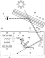
- FIG. 1 is a diagram conceptually showing an example of the HUD projector of the present invention.
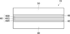
- FIG. 2 is a diagram conceptually showing a reflective member of the HUD projector shown in FIG.
- FIG. 3 is a conceptual diagram for explaining the operation of the conventional reflective member.
- FIG. 4 is a conceptual diagram for explaining the operation of the conventional reflective member.
- FIG. 5 is a conceptual diagram for explaining the operation of the conventional reflective member.
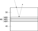
- FIG. 6 is a conceptual diagram for explaining the operation of the reflective member of the present invention.
- FIG. 7 is a conceptual diagram for explaining the operation of the reflective member of the present invention.
- FIG. 8 is a conceptual diagram for explaining the operation of the reflective member of the present invention.
- FIG. 9 is a conceptual diagram for explaining a method of forming an alignment film.
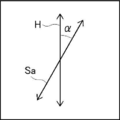
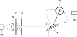
- FIG. 10 is a conceptual diagram for explaining a method for measuring the wavelength dependence of p-polarized reflectance.
- visible light is light having a wavelength visible to the human eye among electromagnetic waves, and indicates light in the wavelength range of 380 to 780 nm.
- Invisible light is light in a wavelength region of less than 380 nm or in a wavelength region of more than 780 nm.
- the light in the wavelength range of 420 to 490 nm is blue light (B light)
- the light in the wavelength range of 495 to 570 nm is green light (G light).
- the light in the wavelength range of 620 to 750 nm is red light (R light).
- infrared rays indicate a wavelength range of more than 780 nm and 2000 nm or less in invisible light.
- p-polarized light means polarized light that oscillates in a direction parallel to the incident surface of light.
- the incident surface means a surface perpendicular to the reflecting surface (such as the surface of the windshield glass) and containing the incident light rays and the reflected light rays.
- the vibration plane of the electric field vector is parallel to the entrance plane.
- the in-plane phase difference (in-plane retardation Re) is a value measured using AxoScan manufactured by Axometrics. Unless otherwise specified, the measurement wavelength is 550 nm.
- projection image means an image based on the projection of light from a projector to be used, not the surrounding landscape such as the front.
- the projected image is observed as a virtual image that appears to emerge beyond the projected image display portion of the windshield glass when viewed from the observer.
- the “screen image” means an image displayed on a drawing device of a projector or an image drawn on an intermediate image screen or the like by the drawing device. In contrast to a virtual image, the image is a real image.
- the "visible light transmittance” is the A light source visible light transmittance defined in JIS R 3212: 2015 (safety glass test method for automobiles). That is, the transmittance of each wavelength in the range of 380 to 780 nm is measured with a spectrophotometer using an A light source, and the transmittance is obtained from the wavelength distribution and wavelength interval of the CIE (International Lighting Commission) light adaptation standard luminous efficiency. It is the transmittance obtained by multiplying the transmittance at each wavelength by the weighting coefficient and weight averaging.
- CIE International Lighting Commission
- liquid crystal composition and the liquid crystal compound include those which no longer exhibit liquid crystal property due to curing or the like as a concept.
- the projector for HUD of the present invention is a projector used for HUD mounted on vehicles such as automobiles and trains, aircraft, and ships.
- FIG. 1 conceptually shows an example of the HUD projector of the present invention.
- the HUD projector 10 of the present invention shown in FIG. 1 includes an image forming unit 12, an intermediate image screen 14, a reflecting member 16, and a concave mirror 18.
- the HUD projector is also simply referred to as a projector.
- the projected light projected by the projector 10 is transmitted to the windshield glass 26 through the transmission window 24 provided on the dashboard 20, and is observed by the user O. Similar to the known HUD, in the HUD of the illustrated example, the user O observes a virtual image of the image projected on the windshield glass 26.
- the HUD using the projector 10 of the present invention is not limited to the HUD (Windshield HUD) that projects the projected image on the windshield glass 26 as shown in the illustrated example. That is, as the HUD using the projector 10 of the present invention, various known HUDs that project the projected image on various members, such as a HUD (combiner HUD) that projects the projected image on a so-called combiner, can be used in various ways.
- the image forming unit 12 includes a light source 30, a mirror 32, a polarizing plate 34, and a light deflector 36.
- the image forming unit 12 is a so-called light beam scanner that forms an image by scanning a light beam.
- the image forming unit 12 emits three light beams modulated according to the projected image from the light source 30, combines the three light beams with the mirror 32, converts them into p-polarized light with the polarizing plate 34, and emits light.
- Two-dimensional scanning is performed by the deflector 36.
- the projector 10 two-dimensionally scans a light beam modulated according to a projected image by an optical deflector 36, creates a real image by an intermediate image screen 14, and converts this real image into a predetermined optical path by a reflecting member 16 and a concave mirror 18. Reflects on. As described above, this reflected light passes through the transmission window 24 provided in the dashboard 20 and is projected onto the windshield glass 26 and observed by the user O (see the alternate long and short dash line).
- the image forming unit 12 has an R light source 30R that emits a red light beam, a G light source 30G that emits a green light beam, and a B light source 30B that emits a blue light beam as the light source 30.
- the light source 30 (R light source 30R, G light source 30G, and B light source 30B) is not limited, and various light sources used for image formation by scanning a light beam can be used. Examples of the light source 30 include an LED (Light Emitting Diode), a discharge tube, a laser light source, and the like.
- the LED includes a light emitting diode, an organic light emitting diode (OLED (Organic Light Emitting Diode), and the like.
- the half-value width of the emitted light of the light source 30 is not limited, but is preferably narrow to some extent.
- the half-value width (half-value full width) of the emitted light of the light source 30 is preferably 20 nm or less, more preferably 15 nm or less, further preferably 10 nm or less, and particularly preferably 7 nm or less.
- the selective reflection layer having a narrow selective reflection region can be used in the reflection member 16 described later, and the projector 10 due to the intrusion of sunlight can be used.
- the effect of the present invention that is, the deterioration of the constituent members can be suitably prevented, and the decrease in the reflectance of the reflecting member due to the fluctuation of the emission wavelength of the light source 30 can be more preferably exhibited. It is preferable in that the image quality is improved.
- the half-value width of the light source 30 is preferably 5 nm or more in terms of brightening the projected light and brightening the virtual image projected on the windshield.
- the wavelengths on the long wavelength side and the short wavelength side which are 50% of the maximum brightness (maximum value) of the emitted light, are found by using a spectrophotometer or the like, and the wavelength on the long wavelength side is found.
- the measurement may be performed by a known method that reduces the wavelength on the short wavelength side from the above.
- the R light source 30R, the G light source 30G, and the B light source 30B are modulated and driven according to the projected image by known control means and driving means (not shown).
- a known light modulator may be used to modulate the light beam emitted by the light source according to the projected image.
- known methods such as intensity modulation and pulse width modulation can be used.
- the image forming unit 12 of the illustrated example corresponds to a full-color projected image that reflects red light, green light, and blue light, but the present invention is not limited to this. That is, in the present invention, the light source 30 has only the R light source 30R and the G light source 30G, or has only the R light source 30R and the B light source 30B, or has only the G light source 30G and the B light source 30B. It may be the one corresponding to the projected image. In this respect, the mirror 32 shown below is also the same.
- the image forming unit 12 includes an R mirror 32R that reflects the emitted light of the R light source 30R, a G mirror 32G that reflects the emitted light of the G light source 30G, and a B mirror 32B that reflects the emitted light of the B light source 30B.
- the R mirror 32R is an ordinary light reflection mirror used in an optical device.
- the G mirror 32G and the B mirror 32B are known dichroic mirrors, the G mirror 32G reflects green light and transmits light in other wavelength ranges, and the B mirror 32B reflects blue light. Then, other light is transmitted.
- the red light beam emitted by the R light source 30R is reflected by the R mirror 32R and passes through the G mirror 32G and the B mirror 32B.
- the green light beam emitted by the G light source 30G is reflected by the G mirror 32G and passes through the B mirror 32B.
- the blue light beam emitted by the B light source 30B is reflected by the B mirror 32B.
- the polarizing plate 34 converts the incident light beam into p-polarized light (p-linearly polarized light).
- the polarizing plate 34 is not limited, and various known linear polarizing plates (linearly polarized lighters) can be used.
- a polarizing plate in which thin films having different refractive index anisotropy are laminated can be mentioned.
- the polarizing plate in which thin films having different refractive index anisotropy are laminated for example, those described in Japanese Patent Publication No. 9-506837 can be used.
- a polarizing plate can be formed using a wide variety of materials.
- one of the first materials needs to have a different refractive index than the second material in the chosen direction.
- This difference in refractive index can be achieved by a variety of methods, including stretching, extrusion, or coating during or after film formation.
- a commercially available product may be used as the polarizing plate in which thin films having different refractive index anisotropy are laminated.
- a product in which a reflective polarizing plate and a temporary support are laminated may be used.
- Examples of commercially available products include DBEF (manufactured by 3M) and APF (Advanced Polarizing Film (manufactured by 3M)).
- an absorption type polarizing plate containing an iodine compound and a general linear polarizing plate such as a reflection type polarizing plate such as a wire grid can also be used.
- the light beam (light beam) modulated according to the projected image polarized by the polarizing plate 34 is two-dimensionally scanned by the light deflector 36.
- the light deflector 36 is not limited, and various known light deflectors capable of scanning a light beam two-dimensionally can be used.
- Examples of the optical deflector 36 include a galvanometer mirror (galvanometer mirror), a combination of a galvanometer mirror and a polygon mirror, and a MEMS (Micro Electro Mechanical Systems). Among them, MEMS is preferably used.
- the scanning method is not limited, and known light beam scanning methods such as random scan and raster scan can be used. Among them, raster scan is preferably exemplified.
- the light beam can be driven, for example, by a resonant frequency in the horizontal direction and by a sawtooth wave in the vertical direction. Since an image formation (drawing) by light beam scanning does not require a projection lens, the device can be easily miniaturized.
- the image forming unit 12 forms a projected image by scanning the light beam, but the present invention is not limited to this. That is, in the projector of the present invention, various known image forming means used in the HUD projector (imager) can be used as the image forming means. Examples of image forming means include a fluorescent display tube, an LCD (Liquid Crystal Display) and LCOS (Liquid Crystal on Silicon) using a liquid crystal display, an organic electroluminescence (organic EL) display, and a DMD (Digital Micromirror Device). Examples include DLP (Digital Light Processing) used. In these image forming means, an image is projected from the projection lens onto the intermediate image screen 14.
- LCD Liquid Crystal Display
- LCOS Liquid Crystal on Silicon
- DMD Digital Micromirror Device
- DLP Digital Light Processing
- the light source in the present invention is the light source of the backlight unit in the case of LCD and LCOP, and the light source for irradiating the DMD with light in the case of DLP, and is an organic EL.
- the display In the case of a display, the display itself is the light source.
- the projected light emitted from the image forming unit 12 is then made into a real image (visible image) by the intermediate image screen 14.
- the intermediate image screen 14 is not limited, and various known intermediate image screens that realize a projected image in a HUD projector can be used.
- Examples of the intermediate image screen 14 include a scattering film, a microlens array, and a screen for rear projection.
- a plastic material is used as the intermediate image screen 14
- the intermediate image screen 14 has birefringence, the polarizing plane and the light intensity of the polarized light incident on the intermediate image screen 14 are disturbed, and as a result, the projected image is colored.
- unevenness and the like are likely to occur, the problem of color unevenness can be reduced by using a retardation layer having a predetermined retardation.
- the intermediate image screen 14 preferably has a function of spreading and transmitting the incident projected light. This is because the projected image can be enlarged and displayed.
- an intermediate image screen composed of a microlens array is exemplified.
- the microarray lens used in the HUD is described in, for example, Japanese Patent Application Laid-Open No. 2012-226303, Japanese Patent Application Laid-Open No. 2010-145745, and Japanese Patent Application Laid-Open No. 2007-523369.
- the projected light realized by the intermediate image screen 14 is reflected by the reflecting member 16 and the concave mirror 18 into a predetermined optical path, transmitted through the transmission window 24 provided on the dashboard 20, and is windowed. It is projected on the shield glass 26 and observed by the user O (see the one-point chain line).
- the reflective member 16 is a characteristic member of the projector 10 of the present invention.
- the reflective member 16 will be described in detail later.
- the concave mirror 18 is a known concave mirror (concave mirror) used in a HUD projector that magnifies and projects the projected light.
- the projector 10 in the illustrated example uses the reflection member 16 and the concave mirror 18 as members for changing the optical path of the projected light, but the present invention is not limited thereto. That is, the projector of the present invention may not have the concave mirror 18 and may have only the reflective member 16 as a member for changing the optical path of the projected light, or in addition to the reflective member 16 and the concave mirror 18. It may have one or more other light reflecting elements. As the light reflecting element, in addition to a concave mirror and a normal mirror, a free curved mirror and the like can be used. That is, as long as the projector of the present invention has the reflecting member of the present invention, a configuration using various light reflecting elements can be used.
- the reflective member 16 is a characteristic member of the present invention.
- the reflective member 16 also acts as a cold mirror, reflects visible light (red light, green light, and blue light) and transmits infrared light.
- the reflective member 16 has a function as a cold mirror that reflects visible light and transmits infrared rays, so that the infrared rays of sunlight that have entered the projector 10 are transmitted through the reflective member 16 as shown by the broken line. To do. Therefore, it is possible to prevent the infrared rays of sunlight from entering the intermediate image screen 14, the light deflector 36, and the polarizing plate 34 and heating and damaging these members. Further, by using the cholesteric liquid crystal layer described later as the selective reflection layer of the reflection member 16, half of the visible light contained in sunlight is transmitted through the reflection member 16, so that the intermediate image screen 14 and the light are more preferable. It is possible to prevent damage to the deflector 36 and the polarizing plate 34 due to heat.
- FIG. 2 conceptually shows an example of the reflective member 16.
- the reflection member 16 includes a substrate 40, an adhesive layer 42, a selective reflection layer 46, a polarization conversion layer 48, and an interference suppression layer 50.
- the reflection member 16 is arranged so that the interference suppression layer 50 is closer to the incident side of the projected light than the selective reflection layer 46. That is, in FIG. 1, the interference suppression layer 50 is on the upper side in the figure with respect to the selective reflection layer 46.
- the projected light incident on the reflection member 16 is transmitted through the interference suppression layer 50, p-polarized light is converted into circularly polarized light by the polarization conversion layer 48, and is reflected by the selective reflection layer 46, and is reflected by the polarization conversion layer. It is returned to p-polarized light by 48, passes through the interference suppression layer 50, and is reflected toward the concave mirror 18.
- the substrate 40 is for supporting the selective reflection layer 46, the polarization conversion layer 48, and the interference suppression layer 50.
- the substrate 40 is not limited, and various plate-like materials (sheet-like materials, films) capable of supporting these layers can be used.
- a resin film made of various glass plates, polyethylene terephthalate (PET), triacetyl cellulose (TAC), acrylic resin (PMMA (Polymethylryl), etc.), and resin materials such as cycloolefin polymer (COP), and , Acrylic board and the like are exemplified.
- the thickness of the substrate 40 is not limited, and the thickness capable of supporting the selective reflection layer 46, the polarization conversion layer 48, and the interference suppression layer 50 may be appropriately set according to the material forming the substrate 40.
- the substrate 40 of the reflective member 16 is not an indispensable constituent requirement.
- the adhesive layer 42 is for adhering the substrate 40 and the selective reflection layer 46.
- the adhesive layer 42 may be formed from an adhesive. From the viewpoint of curing method, there are hot melt type, thermosetting type, photocuring type, reaction curing type, and pressure-sensitive adhesive type that does not require curing, and the materials are acrylate type, urethane type, urethane acrylate type, and epoxy, respectively.
- the photocuring type is preferable as the curing method.
- the material is preferably an acrylate-based material, a urethane acrylate-based material, an epoxy acrylate-based material, or the like.
- the adhesive layer 42 may be formed by using a highly transparent adhesive transfer tape (OCA (Optical Clear Adhesive) tape).
- OCA Optical Clear Adhesive
- a commercially available product for an image display device particularly a commercially available product for the surface of an image display portion of an image display device may be used.
- Examples of commercially available products include an adhesive sheet manufactured by Panac Co., Ltd. (PD-S1 and the like), an adhesive sheet of the MHM series manufactured by Niei Kako Co., Ltd., and the like.
- the thickness of the adhesive layer is preferably 0.5 to 10 ⁇ m, more preferably 1.0 to 5.0 ⁇ m.
- the thickness of the adhesive layer 42 formed by using the OCA tape may be 10 ⁇ m to 50 ⁇ m, preferably 15 ⁇ m to 30 ⁇ m.
- the selective reflection layer 46 is a layer that reflects light in a wavelength-selective manner. Specifically, the selective reflection layer 46 is a layer that selectively reflects light in a specific wavelength range. In the illustrated example, the selective reflection layer 46 selectively reflects light in the wavelength range of visible light and transmits other infrared rays and the like.
- the selective reflection layer 46 is preferably a polarization reflection layer.
- the polarized light reflecting layer is a layer that reflects any of linearly polarized light, circularly polarized light, and elliptically polarized light.
- the polarized light reflecting layer is preferably a circularly polarized light reflecting layer or a linearly polarized light reflecting layer.
- the circularly polarized light reflecting layer is a layer that reflects circularly polarized light of one of the senses (turning direction) and transmits the other in a selective reflection wavelength range.
- the linearly polarized light reflecting layer is a layer that reflects linearly polarized light in one polarization direction at the center wavelength of selective reflection and transmits linearly polarized light in the polarization direction orthogonal to the reflected polarization direction.
- the polarized light reflecting layer can transmit unreflected polarized light. Therefore, by using the polarized light reflecting layer, a part of light can be transmitted even in the wavelength range where the selective reflecting layer 46 shows reflection.
- the selective reflection layer 46 is preferably a circularly polarized light reflection layer, and particularly preferably a cholesteric liquid crystal layer having a fixed cholesteric liquid crystal phase.
- the selective reflection layer 46 of the reflection member 16 shown in FIG. 2 has a red reflection cholesteric liquid crystal layer 46R having a selective reflection center wavelength in the wavelength region of red light and a wavelength of green light when the incident angle is 45 °. It has a green reflective cholesteric liquid crystal layer 46G having a selective reflection center wavelength in the region and a blue reflective cholesteric liquid crystal layer 46B having a selective reflection center wavelength in the wavelength region of blue light.
- the selective reflection center wavelength of each cholesteric liquid crystal layer is preferably within ⁇ 20 nm, more preferably within ⁇ 10 nm, of the peak wavelength of the light source that emits the corresponding light beam among the above-mentioned light sources 30. , It is more preferable that they match. The same applies to the linearly polarized light reflecting layer described later in this respect.
- the reflective member 16 in the illustrated example corresponds to a full-color projected image that reflects red light, green light, and blue light, but the present invention is not limited to this. That is, in the present invention, the selective reflective layer 46 of the reflective member has only the red reflective cholesteric liquid crystal layer 46R and the green reflective cholesteric liquid crystal layer 46G, or has only the red reflective cholesteric liquid crystal layer 46R and the blue reflective cholesteric liquid crystal layer 46B. Alternatively, it may correspond to a two-color cast image having only the green reflective cholesteric liquid crystal layer 46G and the blue reflective cholesteric liquid crystal layer 46B. Alternatively, the selective reflection layer 46 may have three or more cholesteric liquid crystal layers. That is, in the present invention, the reflective member may have two or more cholesteric liquid crystal layers (selective reflection layers) having different selective reflection center wavelengths. The same applies to the linearly polarized light reflecting layer described later in this respect.
- the cholesteric liquid crystal layer means a layer formed by fixing the cholesteric liquid crystal phase.
- the cholesteric liquid crystal layer may be a layer in which the orientation of the liquid crystal compound in the cholesteric liquid crystal phase is maintained.
- the cholesteric liquid crystal layer is typically polymerized and cured by ultraviolet irradiation, heating, etc. after the polymerizable liquid crystal compound is placed in the oriented state of the cholesteric liquid crystal phase to form a non-fluid layer, and at the same time Any layer may be used as long as it is a layer that has changed to a state in which the orientation form is not changed by an external field or an external force.
- the optical properties of the cholesteric liquid crystal phase are retained in the layer, and the liquid crystal compound in the layer does not have to exhibit liquid crystal property anymore.
- the polymerizable liquid crystal compound may lose its liquid crystal property due to its high molecular weight due to the curing reaction.
- the cholesteric liquid crystal phase selectively reflects the circular polarization of one sense of right-handed or left-handed circular polarization and exhibits circular polarization selective reflection that transmits the circular polarization of the other sense. ..
- a film containing a layer in which a cholesteric liquid crystal phase exhibiting circularly polarized selective reflectivity is fixed many films formed from a composition containing a polymerizable liquid crystal compound have been known conventionally, and the cholesteric liquid crystal layer has been conventionally known. You can refer to the technology.
- the spiral pitch P (one spiral pitch) of the spiral structure is, in other words, the length in the spiral axial direction for one spiral winding.
- the spiral pitch P is the length in the spiral axial direction in which the director of the liquid crystal compound constituting the cholesteric liquid crystal phase rotates 360 °.
- the director of the liquid crystal compound is, for example, a rod-shaped liquid crystal in the long axis direction.
- the direction of the spiral axis of the normal cholesteric liquid crystal layer coincides with the thickness direction of the cholesteric liquid crystal layer.
- SEM scanning Electron Microscope
- the spiral pitch P of the cholesteric liquid crystal layer is twice the distance between the bright lines.
- the spiral pitch P of the cholesteric liquid crystal layer is equal to the length of three bright lines and two dark lines in the thickness direction, that is, the length of three dark lines and two bright lines in the thickness direction. This length is the distance between the centers of the upper and lower bright lines or dark lines in the thickness direction.
- the selective reflection center wavelength and the full width at half maximum (full width at half maximum) of the cholesteric liquid crystal layer can be obtained as an example as follows.
- a spectrophotometer manufactured by JASCO Corporation, V-670
- a decrease peak in transmittance is observed in the selective reflection band.
- the value of the wavelength on the short wavelength side is ⁇ l (nm)
- the value of the wavelength on the long wavelength side is ⁇ h (nm)
- the selective reflection center wavelength ⁇ and the half-value width ⁇ can be expressed by the following equations.
- the selective reflection center wavelength obtained as described above substantially coincides with the wavelength at the center of gravity of the reflection peak of the circular polarization reflection spectrum measured from the normal direction of the cholesteric liquid crystal layer.
- the spiral pitch of the cholesteric liquid crystal phase depends on the type of chiral agent used together with the polymerizable liquid crystal compound and the concentration thereof added, a desired pitch can be obtained by adjusting these.
- a desired pitch can be obtained by adjusting these.
- the cholesteric liquid crystal layer is arranged in order from the one having the shortest center wavelength of selective reflection when viewed from the incident side of the light beam.
- each cholesteric liquid crystal layer a cholesteric liquid crystal layer having a spiral sense of either right or left is used.
- the sense of circularly polarized light reflected by the cholesteric liquid crystal layer matches the sense of spiral.
- the sense of circularly polarized light is the turning direction of circularly polarized light. It is preferable that the cholesteric liquid crystal layers having a plurality of layers having different selective reflection center wavelengths have the same sense of spiral, that is, the swirling direction of the reflected circularly polarized light.
- the ⁇ n can be adjusted by adjusting the type or mixing ratio of the polymerizable liquid crystal compound, or by controlling the temperature at the time of fixing the orientation.
- a plurality of cholesteric liquid crystal layers having the same pitch P and the same spiral sense may be laminated. Circular polarization selectivity can be increased at a specific wavelength by laminating cholesteric liquid crystal layers having the same pitch P and the same spiral sense.
- the plurality of cholesteric liquid crystal layers constituting the selective reflection layer 46 may be formed by laminating a separately prepared cholesteric liquid crystal layer using an adhesive or the like, or on the surface of the previous cholesteric liquid crystal layer formed by the method described later.
- a liquid crystal composition (coating liquid) containing a polymerizable liquid crystal compound or the like may be directly applied, and the steps of orientation and fixing may be repeated, but the latter is preferable.
- the next cholesteric liquid crystal layer directly on the surface of the previously formed cholesteric liquid crystal layer the orientation orientation of the liquid crystal molecules on the air interface side of the previously formed cholesteric liquid crystal layer and the cholesteric liquid crystal layer formed on the cholesteric liquid crystal layer. This is because the orientation directions of the lower liquid crystal molecules are the same, and the polarization characteristics of the laminated body of the cholesteric liquid crystal layer are improved. In addition, interference unevenness that may occur due to uneven thickness of the adhesive layer is not observed.
- the thickness of the cholesteric liquid crystal layer is preferably 0.2 to 10 ⁇ m, more preferably 0.3 to 8.0 ⁇ m, and even more preferably 0.5 to 6.0 ⁇ m.
- the total thickness of the cholesteric liquid crystal layer is preferably 1.0 to 30 ⁇ m, more preferably 2.5 to 25 ⁇ m, and even more preferably 3.0 to 20 ⁇ m.
- cholesteric liquid crystal layer a material and a method for producing the cholesteric liquid crystal layer will be described.
- the material used for forming the cholesteric liquid crystal layer described above include a liquid crystal composition containing a polymerizable liquid crystal compound and a chiral agent (optically active compound). If necessary, the above-mentioned liquid crystal composition mixed with a surfactant, a polymerization initiator, etc. and dissolved in a solvent or the like is further applied to a support, an alignment film, a cholesteric liquid crystal layer as an lower layer, or the like, and cholesteric orientation. After aging, the liquid crystal composition can be fixed by curing to form a cholesteric liquid crystal layer.
- the polymerizable liquid crystal compound may be a rod-shaped liquid crystal compound or a disk-shaped liquid crystal compound, but is preferably a rod-shaped liquid crystal compound.
- Examples of the rod-shaped polymerizable liquid crystal compound forming the cholesteric liquid crystal layer include a rod-shaped nematic liquid crystal compound.
- rod-shaped nematic liquid crystal compounds examples include azomethines, azoxys, cyanobiphenyls, cyanophenyl esters, benzoic acid esters, cyclohexanecarboxylic acid phenyl esters, cyanophenylcyclohexanes, cyano-substituted phenylpyrimidines, and alkoxy-substituted phenylpyrimidines.
- Phenyldioxans, trans, and alkenylcyclohexylbenzonitriles are preferably used. Not only low molecular weight liquid crystal compounds but also high molecular weight liquid crystal compounds can be used.
- the polymerizable liquid crystal compound is obtained by introducing a polymerizable group into the liquid crystal compound.
- the polymerizable group include an unsaturated polymerizable group, an epoxy group, and an aziridinyl group, and an unsaturated polymerizable group is preferable, and an ethylenically unsaturated polymerizable group is particularly preferable.
- the polymerizable group can be introduced into the molecule of the liquid crystal compound by various methods.
- the number of polymerizable groups contained in the polymerizable liquid crystal compound is preferably 1 to 6 in one molecule, and more preferably 1 to 3.
- Examples of polymerizable liquid crystal compounds include Makromol. Chem. , 190, 2255 (1989), Advanced Materials 5, 107 (1993), US Pat. No.
- the amount of the polymerizable liquid crystal compound added to the liquid crystal composition is preferably 80 to 99.9% by mass, preferably 85 to 99.5% by mass, based on the solid content mass (mass excluding the solvent) of the liquid crystal composition. % Is more preferable, and 90 to 99% by mass is further preferable.
- the cholesteric liquid crystal layer may have a low ⁇ n.
- the low ⁇ n cholesteric liquid crystal layer can be formed by using a low ⁇ n polymerizable liquid crystal compound.
- the low ⁇ n polymerizable liquid crystal compound will be specifically described.
- a narrow-band selective reflection layer can be obtained by forming a cholesteric liquid crystal phase using a low ⁇ n polymerizable liquid crystal compound and forming a film in which the cholesteric liquid crystal phase is fixed.
- the low ⁇ n polymerizable liquid crystal compound include the compounds described in WO2015 / 115390, WO2015 / 147243, WO2016 / 035773, JP-A-2015-163596, JP-A-2016-053149 and the like.
- the description of WO2016 / 047648 can also be referred to.
- the liquid crystal compound is also preferably a polymerizable compound represented by the following formula (I) described in WO2016 / 047648.
- A represents a phenylene group which may have a substituent or a trans-1,4-cyclohexylene group which may have a substituent
- L is a single bond, -CH 2.
- the phenylene group in the formula (I) is preferably a 1,4-phenylene group.
- the substituent when "may have a substituent" for the phenylene group and the trans-1,4-cyclohexylene group is not particularly limited, and is, for example, an alkyl group, a cycloalkyl group, an alkoxy group, or an alkyl ether. Examples thereof include a substituent selected from the group consisting of a group, an amide group, an amino group, a halogen atom, and a group composed of a combination of two or more of the above-mentioned substituents.
- the phenylene group and the trans-1,4-cyclohexylene group may have 1 to 4 substituents. When having two or more substituents, the two or more substituents may be the same or different from each other.
- the alkyl group may be either linear or branched.
- the alkyl group preferably has 1 to 30 carbon atoms, more preferably 1 to 10 carbon atoms, and even more preferably 1 to 6 carbon atoms.
- Examples of alkyl groups include methyl group, ethyl group, n-propyl group, isopropyl group, n-butyl group, isobutyl group, sec-butyl group, tert-butyl group, n-pentyl group, isopentyl group and neopentyl.
- alkyl group 1,1-dimethylpropyl group, n-hexyl group, isohexyl group, linear or branched heptyl group, octyl group, nonyl group, decyl group, undecyl group, or dodecyl group can be mentioned.
- the above description regarding the alkyl group is the same for the alkoxy group containing the alkyl group.
- specific examples of the alkylene group when referred to as an alkylene group include a divalent group obtained by removing one arbitrary hydrogen atom in each of the above-mentioned examples of an alkyl group.
- the halogen atom include a fluorine atom, a chlorine atom, a bromine atom, and an iodine atom.
- the number of carbon atoms of the cycloalkyl group is preferably 3 to 20, more preferably 5 or more, preferably 10 or less, more preferably 8 or less, still more preferably 6 or less.
- Examples of the cycloalkyl group include a cyclopropyl group, a cyclobutyl group, a cyclopentyl group, a cyclohexyl group, a cycloheptyl group, and a cyclooctyl group.
- X 3 represents a single bond, -O-, -S-, or -N (Sp 4- Q 4 )-, or a nitrogen atom forming a ring structure with Q 3 and Sp 3.
- Sp 3 and Sp 4 are independently one or more-in a single bond, a linear or branched alkylene group having 1 to 20 carbon atoms, and a linear or branched alkylene group having 1 to 20 carbon atoms.
- the replacement position is not particularly limited. Of these, a tetrahydrofuranyl group is preferable, and a 2-tetrahydrofuranyl group is particularly preferable.
- the m-1 Ls may be the same or different from each other.
- Sp 1 and Sp 2 are independently one or more-in a single bond, a linear or branched alkylene group having 1 to 20 carbon atoms, and a linear or branched alkylene group having 1 to 20 carbon atoms.
- the linking group selected from the group consisting of substituted groups is shown.
- Q 1 and Q 2 each independently represent a polymerizable group selected from the group consisting of a hydrogen atom or a group represented by the above formulas Q-1 to Q-5, where Q 1 and Q 2 have . Either one shows a polymerizable group.
- the polymerizable group an acryloyl group (formula Q-1) or a methacryloyl group (formula Q-2) is preferable.
- m represents an integer of 3 to 12.
- m is preferably an integer of 3 to 9, more preferably an integer of 3 to 7, and even more preferably an integer of 3 to 5.
- the polymerizable compound represented by the formula (I) has at least one phenylene group which may have a substituent as A and a trans-1,4-cyclohexylene group which may have a substituent. It is preferable to include at least one.
- the polymerizable compound represented by the formula (I) preferably contains 1 to 4 trans-1,4-cyclohexylene groups which may have a substituent as A, and preferably contains 1 to 3 of them. Is more preferable, and it is more preferable to contain 2 or 3 of them.
- the polymerizable compound represented by the formula (I) preferably contains 1 or more phenylene groups as A, which may have a substituent, and more preferably 1 to 4 groups. It is more preferable to include 3 pieces, and it is particularly preferable to contain 2 or 3 pieces.
- polymerizable compound represented by the formula (I) in addition to the compounds described in paragraphs 0051 to 0058 of WO2016 / 047648, Japanese Patent Application Laid-Open No. 2013-112631, Japanese Patent Application Laid-Open No. 2010-070543, Examples thereof include the compounds described in Japanese Patent No. 4725516, WO2015 / 115390, WO2015 / 147243, WO2016 / 035873, JP-A-2015-163596, and JP-A-2016-053149.
- the chiral agent has the function of inducing the helical structure of the cholesteric liquid crystal phase. Since the chiral compound has a different sense of spiral or spiral pitch depending on the compound, it may be selected according to the purpose.
- the chiral agent is not particularly limited, and known compounds can be used.
- Examples of chiral agents include Liquid Crystal Device Handbook (Chapter 3, 4-3, TN, Chiral Auxiliary for STN, page 199, Japan Society for the Promotion of Science 142, 1989), JP-A-2003-287623, Examples thereof include compounds described in JP-A-2002-302487, JP-A-2002-080478, JP-A-2002-08851, JP-A-2010-181852, and JP-A-2014-034581.
- the chiral agent generally contains an asymmetric carbon atom, but an axial asymmetric compound or a surface asymmetric compound that does not contain an asymmetric carbon atom can also be used as the chiral agent.
- Examples of axially asymmetric or surface asymmetric compounds include binaphthyl, helicene, paracyclophane, and derivatives thereof.
- the chiral agent may have a polymerizable group. When both the chiral agent and the liquid crystal compound have a polymerizable group, the repeating unit derived from the polymerizable liquid crystal compound and the repeating unit derived from the chiral agent are derived by the polymerization reaction between the polymerizable chiral agent and the polymerizable liquid crystal compound.
- the polymerizable group of the polymerizable chiral agent is preferably a group of the same type as the polymerizable group of the polymerizable liquid crystal compound. Therefore, the polymerizable group of the chiral agent is preferably an unsaturated polymerizable group, an epoxy group or an aziridinyl group, more preferably an unsaturated polymerizable group, and preferably an ethylenically unsaturated polymerizable group. Especially preferable.
- the chiral agent may be a liquid crystal compound.
- an isosorbide derivative As the chiral agent, an isosorbide derivative, an isomannide derivative, a binaphthyl derivative and the like can be preferably used.
- As the isosorbide derivative a commercially available product such as LC756 manufactured by BASF may be used.
- the content of the chiral agent in the liquid crystal composition is preferably 0.01 to 200 mol%, more preferably 1 to 30 mol% of the amount of the polymerizable liquid crystal compound.
- the content of the chiral auxiliary in the liquid crystal composition is intended to be the concentration (mass%) of the chiral agent with respect to the total solid content in the composition.
- the liquid crystal composition preferably contains a polymerization initiator.
- the polymerization initiator used is preferably a photopolymerization initiator capable of initiating the polymerization reaction by irradiation with ultraviolet rays.
- photopolymerization initiators include ⁇ -carbonyl compounds (described in US Pat. No. 2,376,661 and US Pat. No. 2,376,670), acidoin ethers (described in US Pat. No. 2,448,828), and ⁇ -hydrogens.
- Substituent aromatic acidoine compound described in US Pat. No.
- an acylphosphine oxide compound or an oxime compound is also preferable to use an acylphosphine oxide compound or an oxime compound as the polymerization initiator.
- acylphosphine oxide compound for example, a commercially available IRGACURE810 (compound name: bis (2,4,6-trimethylbenzoyl) -phenylphosphine oxide) manufactured by BASF Japan Ltd. can be used.
- Oxime compounds include IRGACURE OXE01 (manufactured by BASF), IRGACURE OXE02 (manufactured by BASF), TR-PBG-304 (manufactured by Changzhou Powerful Electronics New Materials Co., Ltd.), ADEKA ARCULS NCI-831 and ADEKA ARCULS NCI.
- a commercially available product such as -930 (manufactured by ADEKA Corporation) can be used. Only one type of polymerization initiator may be used, or two or more types may be used in combination.
- the content of the photopolymerization initiator in the liquid crystal composition is preferably 0.1 to 20% by mass, more preferably 0.5 to 5% by mass, based on the content of the polymerizable liquid crystal compound.
- the liquid crystal composition may optionally contain a cross-linking agent in order to improve the film strength and durability after curing.
- a cross-linking agent one that cures with ultraviolet rays, heat, humidity or the like can be preferably used.
- the cross-linking agent is not particularly limited and may be appropriately selected depending on the intended purpose.
- cross-linking agent examples include polyfunctional acrylate compounds such as trimethylolpropantri (meth) acrylate and pentaerythritol tri (meth) acrylate; epoxy compounds such as glycidyl (meth) acrylate and ethylene glycol diglycidyl ether; 2,2- Aziridine compounds such as bishydroxymethylbutanol-tris [3- (1-aziridinyl) propionate], 4,4-bis (ethyleneiminocarbonylamino) diphenylmethane; isocyanate compounds such as hexamethylenediisocyanate and biuret-type isocyanate; oxazoline group side Polyoxazoline compounds contained in the chain; alkoxysilane compounds such as vinyltrimethoxysilane and N- (2-aminoethyl) 3-aminopropyltrimethoxysilane can be mentioned.
- polyfunctional acrylate compounds such as trimethylolpropantri (meth) acryl
- a known catalyst can be used depending on the reactivity of the cross-linking agent, and the productivity can be improved in addition to the improvement of the film strength and durability. These may be used alone or in combination of two or more.
- the content of the cross-linking agent is preferably 3 to 20% by mass, more preferably 5 to 15% by mass. By setting the content of the cross-linking agent to 3% by mass or more, the effect of improving the cross-linking density can be obtained, and by setting the content of the cross-linking agent to 20% by mass or less, the stability of the cholesteric liquid crystal layer is lowered. Can be prevented.
- "(meth) acrylate” is used in the meaning of "any one or both of acrylate and methacrylate".
- orientation control agent An orientation control agent may be added to the liquid crystal composition, which contributes to the stable or rapid planar orientation of the cholesteric liquid crystal layer.
- the orientation control agent include the fluorine (meth) acrylate-based polymers described in paragraphs [0018] to [0043] of JP-A-2007-272185, and paragraphs [0031]-[0031] of JP-A-2012-203237. 0034] and the like, and examples thereof include compounds represented by the formulas (I) to (IV) described in JP-A-2013-113913.
- the orientation control agent one type may be used alone, or two or more types may be used in combination.
- the amount of the orientation control agent added to the liquid crystal composition is preferably 0.01 to 10% by mass, more preferably 0.01 to 5% by mass, and 0.02 to 1 to the total mass of the polymerizable liquid crystal compound. Mass% is more preferred.
- the liquid crystal composition may contain at least one selected from various additives such as a surfactant for adjusting the surface tension of the coating film and making the thickness uniform, and a polymerizable monomer. .. Further, in the liquid crystal composition, if necessary, a polymerization inhibitor, an antioxidant, an ultraviolet absorber, a light stabilizer, a coloring material, metal oxide fine particles, etc. are added in a range that does not deteriorate the optical performance. Can be added with.
- the cholesteric liquid crystal layer is a liquid crystal composition obtained by dissolving a polymerizable liquid crystal compound, a polymerization initiator, a chiral agent added as necessary, a surfactant, and the like in a solvent, and the interference suppressing layer 50, an alignment film, and polarization conversion. It is applied on the layer 48 or the previously prepared cholesteric liquid crystal layer and dried to obtain a coating film, and the coating film is irradiated with active light to polymerize the cholesteric liquid crystal composition to obtain cholesteric regularity. An immobilized cholesteric liquid crystal layer can be formed.
- the laminated film composed of a plurality of cholesteric liquid crystal layers can be formed by repeating the above-mentioned manufacturing process of the cholesteric liquid crystal layer.
- the solvent used for preparing the liquid crystal composition is not particularly limited and may be appropriately selected depending on the intended purpose, but an organic solvent is preferably used.
- the organic solvent is not particularly limited and may be appropriately selected depending on the intended purpose.
- the method for applying the liquid crystal composition to the support, the alignment film, the cholesteric liquid crystal layer as the lower layer, and the like is not particularly limited and may be appropriately selected depending on the intended purpose.
- the coating method include wire bar coating method, curtain coating method, extrusion coating method, direct gravure coating method, reverse gravure coating method, die coating method, spin coating method, dip coating method, spray coating method, and slide coating. Law etc. can be mentioned. It can also be carried out by transferring the liquid crystal composition separately coated on the support.
- the liquid crystal molecules are oriented by heating the applied liquid crystal composition.
- the heating temperature is preferably 200 ° C. or lower, more preferably 130 ° C. or lower.
- the liquid crystal composition can be cured by further polymerizing the oriented liquid crystal compound.
- the polymerization may be either thermal polymerization or photopolymerization using light irradiation, but photopolymerization is preferable. It is preferable to use ultraviolet rays for light irradiation.
- the irradiation energy is preferably 20mJ / cm 2 ⁇ 50J / cm 2, more preferably 100 ⁇ 1,500mJ / cm 2.
- light irradiation may be carried out under heating conditions or a nitrogen atmosphere.
- the irradiation ultraviolet wavelength is preferably 350 to 430 nm.
- the polymerization reaction rate is preferably high, preferably 70% or more, and more preferably 80% or more.
- the polymerization reaction rate can be determined by measuring the consumption ratio of the polymerizable functional group by measuring the infrared absorption spectrum.
- the reflective member 16 constituting the projector 10 of the present invention may use a linearly polarized light reflective layer as the selective reflective layer.
- the linearly polarized light reflecting layer include a polarizing plate in which thin films having different refractive index anisotropy are laminated.
- Such a polarizing plate has a high visible light transmittance similar to that of the cholesteric liquid crystal layer, and can reflect the projected light incident obliquely when used in the HUD at a wavelength having high visual sensitivity.
- polarizing plate in which thin films having different refractive index anisotropy are laminated, for example, those described in Japanese Patent Publication No. 9-506837 can be used.
- a polarizing plate when processed under the conditions selected to obtain the refractive index relationship, a polarizing plate can be formed using a wide variety of materials.
- one of the first materials needs to have a different refractive index than the second material in the chosen direction.
- This difference in refractive index can be achieved by a variety of methods, including stretching, extrusion, or coating during or after film formation.
- it is preferable to have similar rheological properties eg, melt viscosity
- a commercially available product can be used as the polarizing plate in which thin films having different refractive index anisotropy are laminated.
- a product in which a reflective polarizing plate and a temporary support are laminated may be used.
- Examples of commercially available products include DBEF (manufactured by 3M) and commercially available optical films sold as APF (Advanced Polarizing Film (manufactured by 3M)).
- the thickness of the linearly polarized light reflecting layer is preferably 1.0 to 50 ⁇ m, more preferably 2.0 to 30 ⁇ m.
- the half-value width of the light reflected by the selective reflection layer 46 is not limited, but it is preferably narrow to some extent.
- the half-value width (half-value full width) of the reflected light of the light incident at an incident angle of 45 ° is preferably 70 nm or less, more preferably 50 nm or less, and further preferably 30 nm or less. preferable.
- the half-value width of the reflected light by the selective reflection layer 46 is such that the reflected brightness of the reflected light of the light incident at an incident angle of 45 ° is 50% of the maximum reflected brightness (maximum value) using a spectrophotometer or the like.
- the wavelengths on the wavelength side and the short wavelength side may be known, and the measurement may be performed by a known method of reducing the wavelength on the short wavelength side from the wavelength on the long wavelength side.
- the reflective member 16 has a polarization conversion layer 48 as shown in FIG.
- the polarization conversion layer 48 is arranged between the interference suppression layer 50 and the selective reflection layer 46, but the present invention is not limited thereto.
- the polarization conversion layer 48 may be provided on the surface of the interference suppression layer 50.
- the reflection member 16 is arranged with the interference suppression layer 50 on the incident side of the projected light with respect to the selective reflection layer 46. Further, the image forming unit 12 projects the projected light of p-polarized light.
- the cholesteric liquid crystal layer constituting the selective reflection layer 46 selectively reflects right or left-handed circularly polarized light.
- the polarization conversion layer 48 converts linearly polarized light into circularly polarized light. Specifically, the polarization conversion layer 48 converts the p-polarized light transmitted through the interference suppression layer 50 into circularly polarized light in the turning direction reflected by the cholesteric liquid crystal layer and transmits the circularly polarized light reflected by the cholesteric liquid crystal layer.
- the circularly polarized light in this case includes not only circularly polarized light but also elliptically polarized light. Therefore, the polarization conversion layer 48 is provided on the incident side of the projected light from the image forming unit 12 with respect to the selective reflection layer 46.
- the polarization conversion layer 48 is preferably a ⁇ / 4 retardation layer having a phase difference in the plane direction of ⁇ / 4. Therefore, in the polarization conversion layer 48, for example, the retardation Re in the plane direction at a wavelength of 550 nm is preferably 100 to 450 nm, and more preferably 120 to 200 nm or 300 to 400 nm. Alternatively, as the polarization conversion layer 48, a 3 ⁇ / 4 retardation layer can also be used.
- the retardation layer is positioned on the slow axis so as to convert p-polarized light into circularly polarized light in the turning direction reflected by the cholesteric liquid crystal layer according to the turning direction of the circularly polarized light reflected by the cholesteric liquid crystal layer. Is set and placed.
- the polarization conversion layer 48 is not limited, and any known polarized light can be used as long as it can convert linearly polarized light into circularly polarized light.
- Examples of the polarization conversion layer 48 include a stretched polycarbonate film, a stretched norbornene-based polymer film, a transparent film oriented containing inorganic particles having compound refraction such as strontium carbonate, and an inorganic dielectric on a support. Examples thereof include a thin film obtained by obliquely depositing a body, a film in which a polymerizable liquid crystal compound is uniaxially oriented and fixed, and a film in which a liquid crystal compound is uniaxially oriented and fixed in orientation.
- a film in which a polymerizable liquid crystal compound is uniaxially oriented and fixed in orientation is preferably exemplified as the polarization conversion layer 48.
- a polarization conversion layer 48 as an example, a liquid crystal composition containing a polymerizable liquid crystal compound is applied to the surface of a temporary support or an alignment film, and the polymerizable liquid crystal compound in the liquid crystal composition is nematically applied in a liquid crystal state. After forming in an orientation, it can be fixed by curing to form.
- the formation of the polarization conversion layer 48 in this case can be performed in the same manner as the above-mentioned formation of the cholesteric liquid crystal layer, except that a chiral agent is not added to the liquid crystal composition.
- the heating temperature is preferably 50 to 120 ° C, more preferably 60 to 100 ° C.
- the polarization conversion layer 48 fixes this orientation by applying a composition containing a polymer liquid crystal compound to the surface of a temporary support, an alignment film, or the like to form a nematic orientation in a liquid crystal state, and then cooling the composition. It may be the obtained layer.
- an optical rotation layer formed by fixing a liquid crystal compound twist-oriented with a twist angle of less than 360 ° along a spiral axis extending along a thickness direction and rotating the polarization direction of linearly polarized light. is also available. That is, as the polarization conversion layer 48, an optical rotation layer (optical rotation film) in which a liquid crystal compound is twisted and oriented can also be used.
- the thickness of the polarization conversion layer 48 is not limited, but is preferably 0.2 to 300 ⁇ m, more preferably 0.5 to 150 ⁇ m, and even more preferably 1.0 to 80 ⁇ m.
- the thickness of the polarization conversion layer 48 formed from the liquid crystal composition is not particularly limited, but is preferably 0.2 to 10 ⁇ m, more preferably 0.5 to 5.0 ⁇ m, and further preferably 0.7 to 2.0 ⁇ m. preferable.
- the reflection member 16 has an interference suppression layer 50 having a thickness of 10 ⁇ m or more on the polarization conversion layer 48.
- the reflection member 16 acting as a cold mirror has such an interference suppression layer 50 on the incident side of the projected light from the image forming unit 12 rather than the selective reflection layer 46, so that the light source 30 Even when the wavelength of the light beam emitted by the projector fluctuates, it prevents the brightness of the projected image from being lowered and the color balance of the projected image from being disturbed.
- Patent Document 1 As shown in Patent Document 1, by using a cholesteric liquid crystal layer having a reflection wavelength range for visible light as a reflection member that exerts the action of a cold mirror in a projector, the reflection wavelength range of the cholesteric liquid crystal layer that smoothes only infrared rays. Visible light other than the above can also be transmitted through the reflecting member. Therefore, by using a reflective member having a cholesteric liquid crystal layer, an intermediate image screen and a polarizing plate due to heating by sunlight that penetrates into the projector and travels in the opposite direction to the projected light, as compared with the case of using a normal cold mirror. Etc. can be prevented from deterioration.
- the reflectance decreases when the wavelength of the light beam fluctuates due to heat generation of the light source or the like.
- the brightness of the projected image is lowered, the color balance of the projected image is lost, and the like.
- the decrease in the reflection intensity of the reflecting member due to the wavelength fluctuation of the light beam is large. The present inventor investigated the cause of this.
- the cholesteric liquid crystal layer is thin, the light reflected by the cholesteric liquid crystal layer interferes inside the cholesteric liquid crystal layer of the upper layer (light inlet / output side), and the reflection wavelength characteristic of the cholesteric liquid crystal layer is the maximum reflection wavelength. It was found that it was caused by a large fluctuation in the vicinity of.
- the reflective member 16 of the illustrated example has three cholesteric liquid crystal layers of a red reflective cholesteric liquid crystal layer 46R, a green reflective cholesteric liquid crystal layer 46G, and a blue reflective cholesteric liquid crystal layer 46B from the substrate 40 side. .. Further, the light beam emitted from the light source 30, that is, the projected light is incident from the blue reflective cholesteric liquid crystal layer 46B side.
- the blue light beam Lb is normally reflected by the blue reflective cholesteric liquid crystal layer 46B on the incident surface side.
- the green light beam Lg passes through the blue reflective cholesteric liquid crystal layer 46B and is reflected by the green reflective cholesteric liquid crystal layer 46G.
- the reflected light beam Lg tries to pass through the blue reflective cholesteric liquid crystal layer 46B.
- the blue reflective cholesteric liquid crystal layer 46B is thin, some of the light beams Lg are blue as shown by the broken line in FIG. 4 due to the difference in the refractive index between the blue reflective cholesteric liquid crystal layer 46B and the air interface.
- the red light beam Lr passes through the blue reflective cholesteric liquid crystal layer 46B and the green reflective cholesteric liquid crystal layer 46G and is reflected by the red reflective cholesteric liquid crystal layer 46R.
- the reflected light beam Lr attempts to pass through the green-reflecting cholesteric liquid crystal layer 46G and the blue-reflecting cholesteric liquid crystal layer 46B.
- the green reflective cholesteric liquid crystal layer 46G and the blue reflective cholesteric liquid crystal layer 46B are thin, similarly, some light beams Lr are caused by the difference in refractive index between the blue reflective cholesteric liquid crystal layer 46B and the air interface.
- interference occurs inside the green reflective cholesteric liquid crystal layer 46G and the blue reflective cholesteric liquid crystal layer 46B.
- the polarization conversion layer 48 is on the blue reflective cholesteric liquid crystal layer 46B, such interference also occurs in the polarization conversion layer 48.
- the cholesteric liquid crystal layer having another cholesteric liquid crystal layer on the incident side of the light beam reflects in the vicinity of the selective reflection center wavelength when the wavelength fluctuation of the light beam (projected light) occurs.
- the rate fluctuates and becomes low.
- the cholesteric liquid crystal layer having another cholesteric liquid crystal layer on the incident side of the light beam has a high wavelength dependence of the reflectance in the vicinity of the selective reflection center wavelength.
- the wavelength dependence of this reflectance increases as the half width of the light beam becomes smaller.
- the reflectance fluctuates greatly due to wavelength fluctuations.
- the wavelengths of the green light beam Lg and the red light beam Lr projected light
- the reflection by the red reflection cholesteric liquid crystal layer 46R and the green reflection cholesteric liquid crystal layer 46G The rate is lowered, and the brightness of the projected image is lowered and the color balance is lost.
- the reflection member 16 has an interference suppression layer 50 having a thickness of 10 ⁇ m or more on the incident side of the projected light, that is, the light beam, rather than the selective reflection layer 46.
- the refractive index of the interference suppression layer 50 (refractive index of the resin) is close to that of the cholesteric liquid crystal layer. Therefore, as conceptually shown in FIG. 6, the blue light beam Lb is reflected by the blue reflective cholesteric liquid crystal layer 46B on the incident surface side, and is emitted through the interference suppressing layer 50.
- the green light beam Lg passes through the interference suppression layer 50 and the blue reflective cholesteric liquid crystal layer 46B and is reflected by the green reflective cholesteric liquid crystal layer 46G.
- the reflected light beam Lg penetrates into the blue-reflecting cholesteric liquid crystal layer 46B, but because there is an interference suppression layer 50 having a refractive index close to that of the blue-reflecting cholesteric liquid crystal layer 46B, it transmits through the blue-reflecting cholesteric liquid crystal layer 46B. Then, it penetrates into the interference suppression layer 50.
- the interference suppression layer 50 has a sufficient thickness, even if the difference in refractive index between the interference suppression layer 50 and the air interface is large, interference inside the interference suppression layer 50 does not occur, and FIG. 7 shows. As shown, the light beam Lg is emitted through the interference suppression layer 50.
- the red light beam Lr passes through the interference suppression layer 50, the blue reflective cholesteric liquid crystal layer 46B and the green reflective cholesteric liquid crystal layer 46G, and is reflected by the red reflective cholesteric liquid crystal layer 46R. Will be done.
- the reflected light beam Lr passes through the green-reflecting cholesteric liquid crystal layer 46G and penetrates into the blue-reflecting cholesteric liquid crystal layer 46B. , It penetrates through the blue reflective cholesteric liquid crystal layer 46B and penetrates into the interference suppression layer 50.
- the interference suppression layer 50 has a sufficient thickness, even if the difference in refractive index between the interference suppression layer 50 and the air interface is large, interference inside the interference suppression layer 50 does not occur, and FIG. 8 shows. As shown, the light beam Lr is emitted through the interference suppression layer 50.
- the reflecting member 16 having the interference suppressing layer 50 on the incident side of the projected light with respect to the selective reflecting layer 46 has a wavelength even if the light beam (projected light) has a small half-value width such as 20 nm or less.
- the reflectance does not fluctuate even if. That is, the reflective member 16 has a small wavelength dependence of the reflectance in the vicinity of the selective reflection center wavelength of each color. Therefore, according to the projector 10 of the present invention using the reflecting member 16 having the interference suppressing layer 50 on the incident side of the projected light with respect to the selective reflecting layer 46, the green light beam is generated by the heat generated by the G light source 30G and the R light source 30R. Even if the wavelengths of the Lg and the red light beam Lr fluctuate, the reflectance does not fluctuate, and a projected image with high brightness and color balance can be stably projected.
- the adhesive layer 42 and the polarization conversion layer 48 are omitted in order to simplify the drawings, but the phenomenon that occurs is the same. Further, the same phenomenon occurs when a linearly polarized light reflecting layer is used instead of the selective reflecting layer 46 that selectively reflects circularly polarized light.
- the thickness of the interference suppression layer 50 is 10 ⁇ m or more. If the thickness of the interference suppression layer 50 is less than 10 ⁇ m, the interference of light cannot be sufficiently suppressed, and the wavelength fluctuation of the light beam (projected light) causes a decrease in brightness and an imbalance in color balance.
- the interference suppression layer 50 for preventing the occurrence of interference in the cholesteric liquid crystal layer needs to be thicker as the half width of the light beam is narrower. Further, the thickness of the interference suppressing layer 50 for preventing the occurrence of interference in the cholesteric liquid crystal layer needs to be increased as the wavelength of the light beam becomes longer.
- the thickness of the interference suppression layer 50 is preferably 20 ⁇ m or more in order to prevent interference of the light beam having a half width of 450 nm. Further, in the case of a light beam having a half width of 10 nm, the thickness of the interference suppressing layer 50 is preferably 28 ⁇ m or more in order to prevent interference of the light beam having a half width of 532 nm.
- the thickness of the interference suppressing layer 50 is preferably 40 ⁇ m or more in order to prevent interference of the light beam having a half width of 633 nm. Considering this point, the thickness of the interference suppressing layer 50 is preferably 40 ⁇ m or more, more preferably 80 ⁇ m or more, further preferably 100 ⁇ m or more, and particularly preferably 400 ⁇ m or more.
- the thickness of the interference suppressing layer 50 is preferably 2.0 mm or less in that the reflective member 16 can be prevented from becoming unnecessarily thick, and the reflective member 16 can be prevented from being easily transferred when it has a curvature. More preferably 1.0 mm or less.
- the interference suppression layer 50 preferably has a high visible light transmittance.
- the visible light transmittance of the interference suppression layer 50 is preferably 80% or more, more preferably 85% or more, and even more preferably 90% or more.
- the in-plane retardation Re of the interference suppression layer 50 is not limited, but a smaller one is preferable.
- the in-plane retardation Re of the interference suppression layer 50 is preferably 10 nm or less, more preferably 5 nm or less, and even more preferably 2 nm or less.
- the refractive index of the interference suppressing layer 50 is also not limited, but it is preferable that the difference in refractive index from the cholesteric liquid crystal layer (selective reflective layer) is small.
- the refractive index of the interference suppression layer 50 is preferably 1.45 to 1.6, more preferably 1.5 to 1.58, and even more preferably 1.52 to 1.56.
- the refractive index of the interference suppression layer 50 is also not limited, but the difference in the refractive index from the cholesteric liquid crystal layer (selective reflection layer) can be increased. It is preferable in that it can be made sufficiently small to prevent reflection of light at the interface between the interference suppressing layer 50 and the cholesteric liquid crystal layer.
- the material for forming the interference suppression layer 50 is not limited, and various resin materials can be used as long as a sufficient visible light transmittance can be obtained.
- resin materials such as TAC, COP, PMMA, polycarbonate (PC) and PET, glass, and acrylic plates. Among them, TAC, COP, PMMA and the like are preferably used.
- the reflective member may include an alignment film as a lower layer to which the liquid crystal composition is applied when the cholesteric liquid crystal layer or the retardation layer is formed.
- the alignment film is subjected to rubbing treatment of organic compounds such as polymers (for example, resins such as polyimide, polyvinyl alcohol, polyester, polyarylate, polyamideimide, polyetherimide, polyamide and modified polyamide), oblique deposition of inorganic compounds, and microgrooves.
- LB film Langmuir-Blogget method
- organic compounds for example, ⁇ -tricosanoic acid, dioctadecylmethylammonium chloride and methyl stearylate
- LB film Langmuir-Blogget method
- an alignment film whose alignment function is generated by applying an electric field, applying a magnetic field, or irradiating light may be used.
- the alignment film made of a polymer is subjected to a rubbing treatment and then the liquid crystal composition is applied to the rubbing treated surface.
- the rubbing treatment can be carried out by rubbing the surface of the polymer layer with paper or cloth in a certain direction.
- the liquid crystal composition may be applied to the surface of the interference suppressing layer 50 that has been subjected to the rubbing treatment without providing the alignment film. That is, the interference suppression layer 50 may act as an alignment film.
- the thickness of the alignment film is not limited, but is preferably 0.01 to 5.0 ⁇ m, more preferably 0.05 to 2.0 ⁇ m.
- the alignment layer may be peeled off together with the temporary support. That is, the alignment film exists only when the reflective member is manufactured, and does not have to be a layer constituting the reflective member when the reflective member is completed.
- Such a reflective member 16 can be manufactured by various methods.
- a film to be an alignment film is formed on the surface of a resin film or the like to be an interference suppression layer 50, and an alignment film is formed by a rubbing treatment or the like.
- the polarization conversion layer 48 is formed on the alignment film, and the selective reflection layer 46 such as a cholesteric liquid crystal layer is formed on the surface of the polarization conversion layer.
- a laminate having an interference suppression layer 50 (alignment film), a polarization conversion layer 48, and a selective reflection layer is attached to a substrate 40 such as a glass plate with the selective reflection layer 46 directed by an adhesive layer 42 such as OCA.
- the reflective member 16 is completed.
- the temporary support may be peeled off to form the substrate 40 and the interference suppression layer 50 with an adhesive layer such as OCA.
- the reflective member 16 may have a hard coat layer on the interference suppressing layer 50 (opposite surface of the selective reflective layer 46) in order to improve scratch resistance.
- the hard coat layer is preferably formed using a composition for forming a hard coat layer.
- the composition for forming a hard coat layer preferably contains a compound having three or more ethylenically unsaturated double bond groups in the molecule.
- Examples of the compound having three or more ethylenically unsaturated double bond groups in the molecule include an ester of a polyhydric alcohol and (meth) acrylic acid, vinylbenzene and its derivative, vinylsulfone, and (meth) acrylamide. Can be mentioned. Among them, from the viewpoint of hardness, a compound having three or more (meth) acryloyl groups is preferable, and an acrylate-based compound that forms a cured product having a high hardness widely used in the art can be mentioned. Examples of such a compound include an ester of a polyhydric alcohol and (meth) acrylic acid.
- ester of the polyhydric alcohol and the (meth) acrylic acid examples include pentaerythritol tetra (meth) acrylate, pentaerythritol tri (meth) acrylate, trimethylolpropane tri (meth) acrylate, and EO-modified trimethylolpropane tri (meth).
- Tris (acetyloxyethyl) isocyanurate and the like can be mentioned.
- Specific compounds of polyfunctional acrylate compounds having three or more (meth) acryloyl groups include KAYARAD DPHA, DPHA-2C, PET-30, TMPTA, TPA-320, manufactured by Nippon Kayaku Co., Ltd. TPA-330, RP-1040, T-1420, D-310, DPCA-20, DPCA-30, DPCA-60 and GPO-303, and V manufactured by Osaka Organic Chemical Industry Co., Ltd. Examples thereof include esterified compounds of polyols such as # 400 and V # 36095D and (meth) acrylic acid.
- UV-1400B UV-1700B, UV-6300B, UV-7550B, UV-7600B, UV-7605B, UV-7610B, UV-7620EA, UV-7630B, UV- 7640B, UV-6630B, UV-7000B, UV-7510B, UV-7461TE, UV-3000B, UV-3200B, UV-3210EA, UV-3310EA, UV-3310B, UV- 3500BA, UV-3520TL, UV-3700B, UV-6100B, UV-6640B, UV-2000B, UV-2010B, UV-2250EA and UV-2750B (manufactured by Nippon Synthetic Chemical Co., Ltd.) , UL-503LN (manufactured by Kyoeisha Chemical Co., Ltd.), Unidic 17-806, 17-813, V-4030 and V-4000BA (manufactured by Dainippon Ink and Chemicals Co., Ltd.), EB-1290K, EB-220 , EB-5129,
- the hard coat layer can be formed by applying the above-mentioned composition for forming a hard coat layer to the surface of the interference suppressing layer 50, drying and curing the hard coat layer.
- the hard coat layer can be formed by the following coating method, but is not limited to this method.
- the coating method includes a dip coating method, an air knife coating method, a curtain coating method, a roller coating method, a wire bar coating method, a gravure coating method, a slide coating method, and an extrusion coating method (die coating method) (Japanese Patent Laid-Open No. 2003-164788). (See Gazette) and known methods such as the microgravure coating method are used. Among them, the microgravure coating method and the die coating method are preferable.
- ⁇ Drying and curing conditions for the hard coat layer> a preferable example of a drying and curing method in the case of forming a layer by coating such as a hard coat layer will be described below.
- it is effective to cure by combining irradiation with ionizing radiation and heat treatment before, at the same time as, or after irradiation.
- the patterns of some manufacturing processes are shown below, but are not limited thereto. In the following example, "-" indicates that the heat treatment has not been performed.
- a step of performing heat treatment at the same time as ionizing radiation curing is also preferable.
- the heat treatment is not particularly limited as long as it does not damage the support of the hard coat film and the constituent layers including the hard coat layer, but is preferably 25 to 150 ° C., more preferably 30 to 80 ° C.
- the time required for the heat treatment varies depending on the molecular weight of the component used, the interaction with other components, the viscosity, etc., but is 15 seconds to 1 hour, preferably 20 seconds to 30 minutes, and more preferably 30 seconds to 5 minutes.
- the type of ionizing radiation is not particularly limited, and examples thereof include X-rays, electron beams, ultraviolet rays, visible light, and infrared rays, but ultraviolet rays are widely used.
- the coating film is ultraviolet curable, it is preferable to irradiate each layer with ultraviolet rays having an irradiation amount of 10 to 1000 mJ / cm 2 with an ultraviolet lamp to cure each layer.
- ultraviolet rays having the above-mentioned energy may be applied at once, or may be divided and irradiated.
- the ultraviolet rays in two or more times. More specifically, initially irradiating ultraviolet light of 150 mJ / cm 2 or lower dose, then irradiated with ultraviolet light of 50 mJ / cm 2 or more high dose, and you were later than the initial It is preferable to apply a high irradiation amount of ultraviolet rays.
- the projected light by the projector 10 is transmitted through the transmission window 24 and projected on the windshield glass 26, and the projected image is observed by the user O.
- the reflective member 16 that exerts the action of the cold mirror has the interference suppressing layer 50, the wavelength dependence of the reflectance by the reflective member 16 is small. Therefore, according to the present invention, even if the wavelength of the light beam fluctuates due to heat generation, the reflectance does not fluctuate due to the reflecting member 16, and a projected image with high brightness and color balance can be stably projected. ..
- the windshield glass 26 means a general window glass and windshield of vehicles such as cars and trains, airplanes, ships, motorcycles, and vehicles such as play equipment.
- Examples of the windshield glass 26 include a half mirror film 60 sandwiched between intermediate films 62 and the laminate sandwiched between two flat glass 64 sheets.
- the flat glass 64 is a known flat glass used for windshield glass, and may be flat, curved, or has both a flat surface and a curved surface.
- the interlayer film 62 known ones used as an interlayer film in laminated glass for windshield such as polyvinyl butyral and ethylene-vinyl acetate copolymer can be used.
- the projector 10 incidents the projected light of p-polarized light on the windshield glass 26. Therefore, the half mirror film 60 of the windshield glass 26 preferably reflects p-polarized light.
- the half mirror film 60 that reflects p-polarized light includes a cholesteric liquid crystal layer that selectively reflects red light, a cholesteric liquid crystal layer that selectively reflects green light, and blue light, which are similar to the above-mentioned cholesteric liquid crystal layer.
- An example is a half mirror film 60 having a three-layer cholesteric liquid crystal layer with a cholesteric liquid crystal layer that selectively reflects, and a ⁇ / 4 retardation layer, and the ⁇ / 4 retardation layer is on the incident side of the projected light.
- Each cholesteric liquid crystal layer reflects circularly polarized light in the same turning direction. Further, the ⁇ / 4 retardation layer has a direction of the slow axis so as to convert the incident p-polarized light into circularly polarized light in the turning direction reflected by the cholesteric liquid crystal layer according to the circularly polarized light reflected by the cholesteric liquid crystal layer.
- the ⁇ / 4 retardation layer converts the incident p-polarized light projected into circularly polarized light and is incident on the cholesteric liquid crystal layer, and the cholesteric liquid crystal layer is formed of circularly polarized light. Is reflected and incident on the ⁇ / 4 retardation layer again, and the ⁇ / 4 retardation layer converts the circularly polarized projected light into the p-polarized projected light. As a result, the half mirror film 60 reflects the projected light of p-polarized light.
- the projector of the present invention is not limited to the one that projects the projected light of p-polarized light, and may project the projected image of s-polarized light.
- the projector projects the projected light of s-polarized light
- the projected light is reflected by the surface of the plate glass, so that it is not necessary to incorporate the half mirror film 60 into the windshield glass.
- the projector of the present invention preferably projects p-polarized projected light because it is possible to observe a projected image using polarized sunglasses and it is not necessary to make the windshield glass into a wedge shape.
- compositions 1, 2 and 3 for forming a narrow-band cholesteric liquid crystal layer Composition 1 for forming a narrow-band cholesteric liquid crystal layer in which the following components are mixed to form a narrow-band cholesteric liquid crystal layer having a selective reflection center wavelength of 450 nm at an incident angle of 45 °, and a selective reflection center wavelength of 450 nm at an incident angle of 45 °.
- the formation composition 3 was prepared.
- compositions 1, 2 and 3 for forming a narrow-band cholesteric liquid crystal layer ⁇ ⁇ Rod-shaped liquid crystal compound 101 55 parts by mass ⁇ Rod-shaped liquid crystal compound 102 30 parts by mass ⁇ Rod-shaped liquid crystal compound 201 13 parts by mass ⁇ Rod-shaped liquid crystal compound 202 2 parts by mass ⁇
- Polymerization initiator IRGACURE OXE01 manufactured by BASF 1.0 part by mass, orientation control agent 1 (fluorine-based horizontal alignment agent 1) 0.01 part by mass, orientation control agent 2 (fluorine-based horizontal alignment agent 2) 0.01 part by mass, right-turning chiral agent LC756 ( Made by BASF) Adjusted according to the target selective reflection center wavelength ⁇ Solvent (methyl ethyl ketone) Amount that makes the solute concentration 20% by mass ⁇ ⁇
- Rod-shaped liquid crystal compound 101 Rod-shaped liquid crystal compound 102
- compositions for forming a narrow-band cholesteric liquid crystal layer 1 to 3 were prepared by adjusting the prescription amount of the right-turning chiral agent LC756.
- a single-layer narrow-band cholesteric liquid crystal layer having a film thickness of 4 ⁇ m was prepared on the temporary support in the same manner as in the production of the reflective member shown below, and the visible region was formed. The light reflection characteristics were confirmed.
- the produced narrow-band cholesteric liquid crystal layers are right-handed circularly polarized reflection layers, and the selective reflection center wavelength at an incident angle of 45 ° is 450 nm for the narrow-band cholesteric liquid crystal layer forming composition 1 and the narrow-band cholesteric liquid crystal layer.
- the composition 2 for forming was 530 nm
- the composition 3 for forming a narrow-band cholesteric liquid crystal layer was 630 nm.
- composition for forming a retardation layer The following components were mixed to prepare a composition for forming a retardation layer having the following composition.
- ⁇ Composition for forming a retardation layer ⁇ ⁇ Mixture 1 100 parts by mass ⁇ Orientation control agent 1 0.05 parts by mass ⁇ Orientation control agent 3 (fluorine-based horizontal alignment agent 3) 0.01 parts by mass ⁇ Polymerization initiator IRGACURE OXE01 (manufactured by BASF) 1.0 part by mass ⁇ Solvent (methyl ethyl ketone) Amount that makes the solute concentration 30% by mass ⁇ -
- Example 1 ⁇ Fabrication of reflective member >> ⁇ Saponification of cellulose acylate film>
- a 40 ⁇ m cellulose acylate film (TAC film) obtained by the same production method as in Example 20 of International Publication No. 2014/112575 is passed through a dielectric heating roll having a temperature of 60 ° C. to bring the film surface temperature to 40 ° C.
- an alkaline solution having the composition shown below was applied to one side of the film using a bar coater at a coating amount of 14 mL / m 2 , and heated to 110 ° C. a steam-type far-infrared heater (manufactured by Noritake Company Limited). ) For 10 seconds.
- the cellulose acylate film 1 was saponified by allowing it to stay in a drying zone at 70 ° C. for 5 seconds and drying.
- the refractive index of the cellulose acylate film 1 was measured by a phase difference measuring device (KOBRA-WPR manufactured by Oji Measuring Instruments Co., Ltd.), it was 1.49.
- the in-plane retardation Re of the cellulose acylate film 1 was measured by AxoScan, it was 2 nm.
- composition of composition for forming an alignment film ⁇ ⁇ 28 parts by mass of modified polyvinyl alcohol ⁇ Citric acid ester (AS3, manufactured by Sankyo Chemical Co., Ltd.) 1.2 parts by mass ⁇ Photoinitiator (Irgacure 2959, manufactured by BASF) 0.84 parts by mass ⁇ Glutaraldehyde 2.8 parts by mass ⁇ 699 parts by mass of water and 226 parts by mass of methanol ⁇
- the composition for forming a retardation layer was applied to the rubbed surface of the alignment film on the cellulose acylate film 1 using a wire bar. After that, the coating film is dried and placed on a hot plate at 50 ° C., and in an environment with an oxygen concentration of 1000 ppm or less, an electrodeless lamp "D valve" (60 mW / cm 2 ) manufactured by Fusion UV Systems Co., Ltd. is used for 6 seconds.
- the liquid crystal phase was fixed by irradiating with ultraviolet rays to obtain a ⁇ / 4 layer ( ⁇ / 4 retardation layer) as a polarization conversion layer.
- the in-plane retardation Re of the retardation layer was measured using AxoScan (manufactured by Axometrics) and found to be 142 nm.
- a coating layer was obtained by applying the composition 1 for forming a narrow-band cholesteric liquid crystal layer to the surface of the formed retardation layer at room temperature using a wire bar so that the thickness of the dry film after drying was 4 ⁇ m. ..
- the coating layer is dried at room temperature for 30 seconds, then heated in an atmosphere of 85 ° C. for 2 minutes, and then in an environment with an oxygen concentration of 1000 ppm or less at 60 ° C. using a fusion D-valve (90 mW / cm 2 lamp).
- UV (ultraviolet) irradiation was performed at an output of 60% for 6 to 12 seconds to fix the cholesteric liquid crystal phase, and a narrow band cholesteric liquid crystal layer having a thickness of 4 ⁇ m was obtained.
- the same process was repeated using the composition 2 for forming a narrow-band cholesteric liquid crystal layer on the surface of the obtained cholesteric liquid crystal layer to obtain a narrow-band cholesteric liquid crystal layer having a thickness of 4 ⁇ m.
- the same process was repeated using the composition 3 for forming a narrow-band cholesteric liquid crystal layer on the surface of the obtained cholesteric liquid crystal layer to obtain a narrow-band cholesteric liquid crystal layer having a thickness of 4 ⁇ m.
- a laminate A having a cellulose acylate film 1 having an alignment film, a retardation layer, and a selective reflection layer composed of three narrow-band cholesteric liquid crystal layers was obtained.
- the reflection spectrum of the laminate A was measured with a spectrophotometer (V-670, manufactured by JASCO Corporation). As a result, a reflection spectrum having a selective reflection center wavelength at a wavelength of 450 nm, a wavelength of 530 nm, and a wavelength of 630 nm was obtained at an incident angle of 45 °.
- the reflection spectrum obtained by measurement with a spectrophotometer is quantified, and the difference between the wavelengths on the short wavelength side and the long wavelength side of the reflectance, which is the average value of the maximum and minimum reflectances of each color, is used.
- the half-price width of the reflected light of blue light, the half-price width of the reflected light of green light, and the half-price width of the reflected light of red light at an incident angle of 45 ° were measured.
- the half-value width of the reflected light of blue light at an incident angle of 45 ° was 33 nm
- the half-value width of the reflected light of green light was 40 nm
- the half-value width of the reflected light of red light was 46 nm.
- the produced laminate A was attached to a glass having a thickness of 2 mm by OCA (MHM-UHV15, manufactured by Niei Kako Co., Ltd.). The sticking was performed with the cholesteric liquid crystal layer (selective reflective layer) facing the glass. This glass serves as a substrate for the reflective member. As a result, a reflective member having a layer structure of glass / OCA / narrow band cholesteric liquid crystal layer / ⁇ / 4 layer / interference suppression layer (TAC) was produced.
- Example 2 A reflective member was produced in the same manner as in Example 1 except that the retardation layer ( ⁇ / 4 layer) was not formed as the polarization conversion layer.
- the layer structure of the produced reflective member is as follows. Glass / OCA / Narrow band cholesteric liquid crystal layer / Interference suppression layer (TAC)
- Example 3 Composition for forming optical rotation layer
- the following components were mixed to prepare a composition for forming an optical rotation layer having the following composition.
- ⁇ Composition for forming an optical rotation layer ⁇
- Mixture 1 100 parts by mass ⁇ Orientation control agent 1 0.05 parts by mass ⁇ Orientation control agent 3 0.02 parts by mass ⁇
- Right swivel chiral agent LC756 (manufactured by BASF) 1.69 parts by mass ⁇
- Polymerization initiator IRGACURE OXE01 (Made by BASF) 1.0 part by mass ⁇ Solvent (methyl ethyl ketone) Amount that makes the solute concentration 20% by mass ⁇ -
- a reflective member was produced in the same manner as in Example 1 except that the optical rotation layer as the polarization conversion layer was similarly formed by using this optical rotation layer forming composition instead of the retardation layer forming composition. did.
- a composition for forming a polarization conversion layer was prepared so that the selective reflection center wavelength ⁇ was 1550 nm when the cholesteric liquid crystal layer was used, and the coating film was prepared so that the number of pitches was 0.7.
- the thickness was 0.7 ⁇ m.
- the layer structure of the produced reflective member is as follows. Glass / OCA / Narrow band cholesteric liquid crystal layer / Optical rotation layer / Interference suppression layer (TAC)
- the selective reflection center wavelength is 450 nm, 530 nm, and 630 nm at an incident angle of 45 °, and the reflectance is 40%.
- a linearly polarized light reflecting plate was produced by forming 2,6-polyethylene naphthalate (PEN) and copolyester (coPEN) of naphthalate 70 / terephthalate 30 by adjusting the thickness of each layer. The linearly polarized light reflector was adjusted so that the average refractive index difference between PEN and coPEN was about 0.1 in order to narrow the reflected light.
- PEN 2,6-polyethylene naphthalate
- coPEN copolyester
- a reflective member was produced in the same manner as in Example 1 except that the ⁇ / 4 layer and the cholesteric liquid crystal layer were not formed on the cellulose acylate film 1 and the linearly polarized light reflector was attached using OCA.
- the layer structure of the produced reflective member is as follows. Glass / OCA / Narrowband linearly polarized light reflector / OCA / Interference suppression layer (TAC)
- Example 5 ⁇ Preparation of hard coat layer composition> Each component was mixed so as to have the following composition, and a hard coat layer composition having a solid content concentration of about 51% by mass was prepared.
- Hard coat layer composition ⁇ -Dipentaerythritol polyacrylate: A-9550W (manufactured by Shin-Nakamura Chemical Industry Co., Ltd.) (six-functional) 44.8 parts by mass-Alkylphenone-based photopolymerization initiator (Ilcagua 184, manufactured by BASF) 4 parts by mass 3,4-epoxycyclohexylmethylmethacrylate: Cyclomer M100 (manufactured by Daicel, molecular weight 196) 22.5 parts by mass, compound 1 0.80 parts by mass, polymer surfactant (manufactured by Dainippon Chemical Industries, Ltd., B1176) 0.05 parts by mass, spherical silica fine particles (manufactured by Nissan Chemical Industries, Ltd.,
- a hard coat layer was prepared by using the prepared hard coat layer composition on the surface of the interference suppression layer of the reflective member prepared in Example 1. Specifically, the hard coat layer composition is applied using a bar at a transport speed of 10 m / min, dried at 60 ° C. for 150 seconds, and then 160 W / at an oxygen concentration of about 0.1% by volume under nitrogen purging. using cm 2 air-cooled metal halide lamp (manufactured by eye graphics Co., Ltd.), intensity 400 mW / cm 2, to form a hard coat layer to cure the coated layer to an irradiation dose of 500 mJ / cm 2.
- cm 2 air-cooled metal halide lamp manufactured by eye graphics Co., Ltd.
- the film thickness of the hard coat layer was measured using a contact type film thickness meter. Specifically, first, the film thickness of the reflective member of Example 5 having a hard coat layer is measured using a contact-type film thickness meter, and similarly, the film thickness of the reflective member of Example 1 is measured. did. Next, the film thickness of the hard coat layer was calculated by subtracting the film thickness of the projected image display member of Example 12 without the hard coat layer from the film thickness of the reflective member of Example 16 having the hard coat layer. The film thickness of the hard coat layer was 6.0 ⁇ m.
- Example 6 A reflective member was produced in the same manner as in Example 1 except that the thickness of the cellulose acylate film (TAC) to be the interference suppressing layer was set to 12 ⁇ m.
- Example 7 A reflective member was produced in the same manner as in Example 1 except that the thickness of the cellulose acylate film (TAC) to be the interference suppressing layer was set to 25 ⁇ m.
- Example 8 A reflective member was produced in the same manner as in Example 1 except that the thickness of the cellulose acylate film (TAC) to be the interference suppressing layer was set to 100 ⁇ m.
- the layer structure of the reflective member in the above example is as follows. Glass / OCA / Narrow band cholesteric liquid crystal layer / ⁇ / 4 layer / Interference suppression layer (TAC)
- Example 9 After preparing the laminated body A in the same manner as in Example 1, the cellulose acylate film 1 was peeled off. After the cellulose acylate film 1 was peeled off, a glass plate having a thickness of 1 mm was attached as an interference suppressing layer to the laminate of the ⁇ / 4 layer and the three cholesteric liquid crystal layers using OCA. The sticking was performed by facing the ⁇ / 4 layer and the glass plate. From this point onward, a reflective member was produced in the same manner as in Example 1. The layer structure of the produced reflective member is as follows. Glass / OCA / Narrow band cholesteric liquid crystal layer / ⁇ / 4 layer / OCA / Glass
- Example 10 A reflective member was produced in the same manner as in Example 1 except that the order of formation of the ⁇ / 4 layer and the cholesteric reflective layer (selective reflective layer) was reversed.
- the layer structure of the produced reflective member is as follows. Glass / OCA / ⁇ / 4 layer / Narrow band cholesteric liquid crystal layer / Interference suppression layer (TAC)
- a cholesteric liquid crystal layer forming composition 5 for forming a liquid crystal layer and a cholesteric liquid crystal layer forming composition 6 for forming a cholesteric liquid crystal layer having an incident angle of 45 ° and a selective reflection center wavelength of 630 nm were prepared.
- compositions 4 to 6 for forming a cholesteric liquid crystal layer were prepared into compositions 4 to 6 for forming a cholesteric liquid crystal layer by adjusting the prescription amount of the right-turning chiral agent LC756.
- a single-layer cholesteric liquid crystal layer having a film thickness of 4 ⁇ m was produced on the temporary support in the same manner as in the production of the reflection member described above, and the reflection characteristics of visible light were exhibited. confirmed.
- all of the produced cholesteric liquid crystal layers are right-handed circularly polarized light reflecting layers, and the selective reflection center wavelength at an incident angle of 45 ° is 450 nm for the cholesteric liquid crystal layer forming composition 4 and 450 nm for the cholesteric liquid crystal layer forming composition 5.
- the wavelength was 530 nm, and the composition 6 for forming a cholesteric liquid crystal layer was 630 nm.
- a reflective member was produced in the same manner as in Example 1 except that the cholesteric liquid crystal layer forming compositions 4 to 6 were used for forming the selective reflective layer (cholesteric liquid crystal layer).
- the layer structure of the produced reflective member is as follows. Glass / OCA / Cholesteric liquid crystal layer / ⁇ / 4 layer / Interference suppression layer (TAC)
- Example 3 A three-layer narrow-band cholesteric liquid crystal layer (selective reflection layer) was produced on the cellulose acylate film 1 on which the alignment film was formed in the same manner as in Example 1. Next, the interference suppression layer (TAC) was faced with the glass plate, and the glass plate was attached by OCA in the same manner as in Example 1.
- the layer structure of the produced reflective member is as follows. Glass / OCA / Interference suppression layer (TAC) / Narrow band cholesteric liquid crystal layer
- a reflective member was produced in the same manner as in Example 1 except that the thickness of the cellulose acylate film (TAC) to be the interference suppressing layer was set to 8 ⁇ m.
- the layer structure of the reflective member in the above example is as follows. Glass / OCA / Narrow band cholesteric liquid crystal layer / ⁇ / 4 layer / Interference suppression layer (TAC)
- the in-plane retardation Re of the interference suppression layer and the half width of reflection of the cholesteric liquid crystal layer were measured in the same manner as in Example 1.
- the light beam (single-point chain line) emitted by the light source 70 is made into parallel light by the collimator lens 72, is made into p-polarized light by the polarizer 74, and is converted into p-polarized light by a reflector 74, and is a reflective member as a sample through a regulation plate 76 having a circular aperture of 1 mm in diameter. It was incident on S. The reflected light from the reflecting member S was incident on the integrating sphere 78, and the amount of reflected light was measured by the spectroscope 80.
- the reflective member S was arranged so that the longitudinal direction of the cellulose acylate film 1 (TAC) at the time of production was parallel to the polarization direction of p-polarized light.
- TAC cellulose acylate film 1
- the slow axis of the ⁇ / 4 layer is 45 ° with respect to the polarization direction of p-polarized light.
- the interference suppression layer TAC, glass
- Example 5 the hard coat layer was used, in Comparative Examples 1 and 3, the cholesteric liquid crystal layer was used, and in Comparative Example 2, the ⁇ / 4 layer was used as the incident surface of the light beam.
- the angle of incidence ⁇ of the light beam (dashed line) on the reflective member S is changed in 1 ° increments from 40 to 50 ° by swinging the reflective member S. I went. Further, as necessary, the position of the integrating sphere 78 was moved as shown by the arrow p in the figure.
- a selective reflection layer such as a cholesteric liquid crystal layer causes a so-called blue shift (short wave shift) in which the reflection wavelength becomes shorter as the incident angle with respect to the normal increases. Utilizing this, the wavelength variation of the light beam was imitated by changing the incident angle ⁇ of the light beam on the reflection member S. The variation in reflectance was calculated with the case where the amount of reflected light was the highest as 100%.
- the wavelength dependence of the p-polarized reflectance was evaluated using the following evaluation criteria using the maximum value of the reflectance variation.
- a Reflectance fluctuation is less than 2%
- B + Reflectance fluctuation is 2% or more and less than 3%
- B Reflectance fluctuation is 3% or more and less than 5%
- C Reflectance fluctuation is 5% or more Even if the wavelength of is changed, the HUD image is hardly affected.
- the B + evaluation is a level at which the tint of the HUD image changes slightly when the wavelength of the light beam changes due to heat.
- the B evaluation is a level at which the color of the HUD image changes to the extent that it does not pose a problem in practical use when the wavelength of the light beam changes due to heat.
- the C evaluation is a level at which the color of the HUD image changes when the wavelength of the light beam changes due to heat.
- P-polarized light is incident from a direction of 45 ° with respect to the normal direction of the reflecting member, and its specular reflected light (in the incident plane, opposite to the normal direction with respect to the incident direction, 45 ° with respect to the normal direction).
- the reflectance spectrum was measured with a spectrophotometer (manufactured by Nippon Kogaku Co., Ltd., V-670).
- the reflective member S was arranged so that the longitudinal direction of the cellulose acylate film 1 (TAC) at the time of production was parallel to the polarization direction of p-polarized light.
- the slow axis of the ⁇ / 4 layer is 45 ° with respect to the polarization direction of p-polarized light.
- the interference suppression layer TAC, glass
- Example 5 the hard coat layer was used, in Comparative Examples 1 and 3, the cholesteric liquid crystal layer was used, and in Comparative Example 2, the ⁇ / 4 layer was used as the incident surface of the light beam.
- the reflectance is multiplied by the coefficient according to the visual sensitivity and the emission spectra of the laser imagers at 450 nm, 515 nm, and 633 nm to calculate the projected image reflectance as the brightness. evaluated.
- Luminance was evaluated according to the following evaluation criteria. A 70% or more B 30% or more to less than 70% C less than 30% A rating is the level at which most of the light beam is reflected and the image is visible on the HUD's P-polarized light reflection system.
- the C rating is a level at which the light beam is hardly reflected and the image cannot be seen by the P polarization reflection system of the HUD.
- Natural light is incident from the interference suppression layer (TAC) surface of the reflective member from a direction of 45 ° with respect to the normal direction of the interference suppression layer, and the transmitted light is measured by a spectrophotometer (V-670, manufactured by JASCO Corporation). The transmittance spectrum was measured.
- TAC interference suppression layer
- V-670 spectrophotometer
- Example 5 the hard coat layer was used, in Comparative Examples 1 and 3, the cholesteric liquid crystal layer was used, and in Comparative Example 2, the ⁇ / 4 layer was used as the incident surface of natural light.
- the transmittance of natural light was calculated by multiplying the reflectance by a coefficient corresponding to the luminosity factor and the emission spectrum of the D65 light source, and evaluated as the amount of sunlight cut.
- the effect of the amount of solar cut was evaluated according to the following evaluation criteria.
- the B evaluation is a level at which a part of visible light is transmitted and a part of sunlight returns to a member upstream of the reflecting member.
- the C rating is a level at which visible light is slightly transmitted and sunlight is almost returned to the member upstream of the reflecting member. The results are shown in the table below.
- the decrease in the reflectance of the reflecting member with respect to the wavelength fluctuation of the light beam (projected light) is suppressed.
- fluctuations in the tint of the image projected by the HUD and a decrease in brightness can be suitably suppressed.
- Example 10 by providing a polarization conversion layer such as a ⁇ / 4 plate and an optical rotation layer on the light incident side of the cholesteric liquid crystal layer which is a selective reflection layer.
- the p-polarized light reflectance can be improved.
- a linearly polarized light reflecting layer can also be preferably used as the selective reflecting layer.
- Example 1 and Example 11 by setting all the reflection half widths of the cholesteric liquid crystal layer to 70 nm or less, a high sunlight blocking effect can be obtained.
- Comparative Examples 1 and 2 having no interference suppression layer Comparative Example 3 in which the cholesteric liquid crystal layer is located on the incident side of the light beam from the interference suppression layer, and the thickness of the interference suppression layer
- Comparative Examples 4 which are insufficient, the reflectance of the reflecting member is greatly reduced with respect to the wavelength fluctuation of the light beam, and the color of the image projected by the HUD is fluctuated. From the above results, the effect of the present invention is clear.
Abstract
Description
HUDによれば、運転者は、前方の外界を見ながら、視線を大きく動かすことなく、地図、走行速度、および、車両の状態など、様々な情報を得ることができるため、各種の情報を得ながら、より安全に運転を行うことが期待できる。
例えば、車両に搭載されたHUDであれば、ウインドシールドガラスから入射した太陽光等が、ダッシュボードに設けられた透過窓を透過してダッシュボードの内部に侵入して、プロシェクターの内部に侵入し、投映光とは逆の光路で進行する。
この投映光とは逆の光路によって進行する太陽光によって、プロジェクターを構成する各種の部材、例えば、ミラー、偏光板、中間像スクリーンおよび光源(画像形成手段)等の各種の部材が加熱され、劣化する。
ここで、HUD用のプロジェクターでは、上述した太陽光による構成部材の劣化防止を目的として、ミラーとして、コールドミラーが用いられる。コールドミラーとは、可視光は反射して、赤外線は透過するミラーである。
コールドミラーを投映光の光路に配置することにより、プロジェクターの内部に侵入した太陽光のうち、最も大きな加熱源となる赤外線は、コールドミラーを透過するので、これ以上、投映光の光路を逆に進行することを防止できる。従って、コールドミラーを用いることで、コールドミラーよりも投映光の光路の上流に位置する部材が、太陽光によって劣化することを防止できる。
コレステリック液晶層とは、コレステリック液晶相を固定してなる層である。周知のように、コレステリック液晶相は、特定の旋回方向の円偏光の、特定の波長域の光を選択的に反射する。
特許文献1には、プロジェクターを構成する反射部材(選択反射板)として、青色光を選択的に反射するコレステリック液晶層と、緑色光を選択的に反射するコレステリック液晶層と、赤色光を選択的に反射するコレステリック液晶層とを有する偏光選択反射層を有する反射部材を用いている。
そのため、コレステリック液晶層のような波長選択性を有する選択反射層を用いる反射部材によれば、赤外線のみならず、可視光による部材の加熱も防止でき、HUDのプロジェクターを構成する部材の太陽光による劣化を、より好適に低減できる。
ところが、コレステリック液晶層のような選択反射層を利用する反射部材は、反射率の波長依存性が高い。そのため、光ビームによって画像を形成するHUD用のプロジェクターに、選択反射層を利用する反射部材を用いると、光源の発熱等によって光ビームの波長が変動した場合に、反射率が低下してしまい、投映像の輝度低下、および、投映像の色バランスの崩れ等が生じてしまう。
[1] 投映像を形成するための光源と、
可視光を反射する、選択反射中心波長が互いに異なる2層以上の選択反射層、および、厚さが10μm以上の干渉抑制層を有する反射部材と、を有し、
反射部材において、干渉抑制層は、選択反射層よりも光源からの光の入射側に位置する、ヘッドアップディスプレイ用プロジェクター。
[2] 選択反射層は、入射角45°で入射した可視光を反射した反射光の半値幅が70nm以下である、[1]に記載のヘッドアップディスプレイ用プロジェクター。
[3] 光源は、出射光の半値幅が20nm以下である、[1]または[2]に記載のヘッドアップディスプレイ用プロジェクター。
[4] 干渉抑制層の厚さが40μm以上である、[1]~[3]のいずれかに記載のヘッドアップディスプレイ用プロジェクター。
[5] 選択反射層が、コレステリック液晶相を固定してなるコレステリック液晶層である、[1]~[4]のいずれかに記載のヘッドアップディスプレイ用プロジェクター。
[6] 反射部材が、直線偏光を円偏光に変換する偏光変換層を有する、[1]~[5]のいずれかに記載のヘッドアップディスプレイ用プロジェクター。
[7] 偏光変換層の面方向のレタデーションReが100~450nmである、[6]に記載のヘッドアップディスプレイ用プロジェクター。
[8] 偏光変換層が、厚さ方向に沿って伸びる螺旋軸に沿って、360°未満の捩れ角で捩れ配向した液晶化合物を固定してなる層である、[6]または[7]に記載のヘッドアップディスプレイ用プロジェクター。
[9] 偏光変換層が、干渉抑制層と選択反射層との間に配置される、[6]~[8]のいずれかに記載のヘッドアップディスプレイ用プロジェクター。
[10] 選択反射層が、直線偏光反射層である、[1]~[4]のいずれかに記載のヘッドアップディスプレイ用プロジェクター。
本明細書において、「画像(screen image)」はプロジェクターの描画デバイスに表示される像または、描画デバイスにより中間像スクリーン等に描画される像を意味する。虚像に対して、画像は実像である。
図1に示す本発明のHUD用プロジェクター10は、画像形成部12と、中間像スクリーン14と、反射部材16と、凹面ミラー18と、を有して構成される。
以下の説明では、HUD用プロジェクターを、単にプロジェクターともいう。
なお、公知のHUDと同様、図示例のHUDでも、使用者Oは、ウインドシールドガラス26に投映された画像の虚像を観察している。
画像形成部12は、光ビームの走査によって画像を形成する、いわゆる光ビームスキャナーである。
プロジェクター10は、投映像に応じて変調した光ビームを、光偏向器36によって二次元的に走査して、中間像スクリーン14によって実像化し、この実像を反射部材16および凹面ミラー18によって所定の光路に反射する。この反射光は、上述のように、ダッシュボード20に設けられた透過窓24を透過して、ウインドシールドガラス26に投映され、使用者Oによって観察される(一点鎖線参照)。
光源30(R光源30R、G光源30GおよびB光源30B)には、制限はなく、光ビームの走査による画像形成に用いられる光源が、各種、利用可能である。
光源30としては、一例として、LED(Light Emitting Diode)、放電管、および、レーザー光源等が例示される。なお、LEDには、発光ダイオード、および、有機発光ダイオード(OLED(Organic Light Emitting Diode)等を含む。
光源30の発光光の半値幅(半値全幅)は、20nm以下が好ましく、15nm以下がより好ましく、10nm以下さらにが好ましく、7nm以下が特に好ましい。
光源30の半値幅を20nm以下とすることにより、後述する反射部材16において、選択的な反射域(反射の半値幅)が狭い選択反射層を用いることができ、太陽光の侵入によるプロジェクター10の構成部材の劣化を好適に防止できる、光源30の出射波長の変動に起因する反射部材の反射率の低下を防止できるという本発明の効果を、より好適に発現できる、フロントガラスに投映した虚像の画質が向上する等の点で好ましい。
投映光を明るくできる、フロントガラスに投映した虚像を明るくできる等の点で、光源30の半値幅は、5nm以上が好ましい。
また、光源30が市販品であれば、半値幅はカタログ値を用いてもよい。
変調は、強度変調およびパルス幅変調等の公知の方法が利用可能である。
すなわち、本発明において、光源30は、R光源30RおよびG光源30Gのみを有する、または、R光源30RおよびB光源30Bのみを有する、または、G光源30GおよびB光源30Bのみを有する、2色の投映像に対応するものでもよい。
この点に関しては、以下に示すミラー32も同様である。
Rミラー32Rは、光学装置に用いられる通常の光反射ミラーである。また、Gミラー32GおよびBミラー32Bは、公知のダイクロイックミラーであり、Gミラー32Gは、緑色光を反射して、それ以外の波長域の光を透過し、Bミラー32Bは、青色光を反射して、それ以外の光を透過する。
これにより、赤色、緑色および青色の3本の光ビームが、1本の光ビームに合波されて、偏光板34に入射される。
偏光板34には、制限はなく、公知の直線偏光板(直線偏光子)が、各種、利用可能である。
偏光板34としては、一例として、屈折率異方性の異なる薄膜を積層した偏光板が挙げられる。屈折率異方性の異なる薄膜を積層した偏光板としては、例えば特表平9-506837号公報などに記載されたものを用いることができる。具体的には、屈折率関係を得るために選ばれた条件下で加工すると、広く様々な材料を用いて、偏光板を形成できる。
一般に、第1の材料の一つが、選ばれた方向において、第2の材料とは異なる屈折率を有することが必要である。この屈折率の違いは、フィルムの形成中、またはフィルムの形成後の延伸、押出成形、或いはコーティングを含む様々な方法で達成できる。さらに、2つの材料が同時押出することができるように、類似のレオロジー特性を有することが好ましい。レオロジー特性としては、例えば、溶融粘度が例示される。
市販品としては、反射型偏光板と仮支持体との積層体となっているものを用いてもよい。市販品としては、例えば、DBEF(3M社製)、および、APF(高度偏光フィルム(Advanced Polarizing Film(3M社製))等が挙げられる。
光偏向器36には、制限はなく、二次元的に光ビームを走査可能な公知の光偏向器が、各種、利用可能である。光偏向器36としては、一例として、ガルバノミラー(ガルバノメーターミラー)、ガルバノミラーとポリゴンミラーとの組み合わせ、および、MEMS(Micro Electro Mechanical Systems、微小電子機械システム)等が例示される。中でも、MEMSは、好適に利用される。
ラスタースキャンにおいて、光ビームは、例えば、水平方向は共振周波数で、垂直方向はのこぎり波で駆動されることができる。光ビーム走査による画像形成(描画)は投射レンズが不要であるため、装置の小型化が容易である。
すなわち、本発明のプロジェクターにおいて、画像形成手段としては、HUDのプロジェクター(イメージャー)で利用されている公知の画像形成手段が、各種、利用可能である。画像形成手段としては、一例として、蛍光表示管、液晶を利用するLCD(Liquid Crystal Display)およびLCOS(Liquid Crystal on Silicon)、有機エレクトロルミネッセンス(有機EL)ディスプレイ、ならびに、DMD(Digital Micromirror Device)を用いるDLP(Digital Light Processing)等が例示される。これらの画像形成手段では、投映レンズから、中間像スクリーン14に画像が投映される。
なお、これらの画像形成手段において、本発明における光源は、LCDおよびLCOPの場合には、バックライトユニットの光源であり、DLPである場合には、DMDに光を照射する光源であり、有機ELディスプレイの場合には、ディスプレイそのものが光源となる。
中間像スクリーン14には、制限はなく、HUDのプロジェクターにおいて、投映像を実像化する公知の中間像スクリーンが、各種、利用可能である。
このような中間像スクリーンとしては、一例として、マイクロレンズアレイで構成される中間像スクリーンが例示される。HUDで用いられるマイクロアレイレンズについては、例えば、特開2012-226303号公報、特開2010-145745号公報、および、特表2007-523369号公報等に記載がある。
反射部材16は、本発明のプロジェクター10の特徴的な部材である。反射部材16に関しては、後に詳述する。
一方、凹面ミラー18は、投映光を拡大投映する、HUDのプロジェクターに用いられる公知の凹面ミラー(凹面鏡)である。
すなわち、本発明のプロジェクターは、凹面ミラー18を有さず、投映光の光路を変更する部材として反射部材16のみを有するものであってもよく、または、反射部材16および凹面ミラー18に加え、他の光反射素子を、1以上、有してもよい。
光反射素子としては、凹面ミラーおよび通常のミラーに加え、自由曲面ミラー等も利用可能である。すなわち、本発明のプロジェクターは、本発明における反射部材を有するものであれば、各種の光反射素子を用いた構成が利用可能である。
反射部材16は、コールドミラーとしての作用も有するもので、可視光(赤色光、緑色光および青色光)を反射して、赤外線を透過する。
ここで、これらの部材を加熱するのは、主に、太陽光に含まれる赤外線である。従って、反射部材16が、可視光を反射して、赤外線を透過するコールドミラーとしての機能を有することで、プロジェクター10に侵入した太陽光の赤外線は、破線で示すように、反射部材16を透過する。従って、太陽光の赤外線が中間像スクリーン14、光偏向器36、および、偏光板34に入射して、これらの部材が加熱して損傷することを防止できる。
また、反射部材16の選択反射層を、後述するコレステリック液晶層とすることにより、太陽光に含まれる可視光も、半分、反射部材16を透過するので、より好適に、中間像スクリーン14、光偏向器36および偏光板34の熱による損傷を防止できる。
図2に示すように、反射部材16は、基板40と、接着層42と、選択反射層46と、偏光変換層48と、干渉抑制層50とを有する。
本発明のプロジェクター10において、反射部材16は、干渉抑制層50を、選択反射層46よりも投映光の入射側にして配置される。すなわち、図1においては、干渉抑制層50が選択反射層46よりも図中上側になる。従って、後述するが、反射部材16に入射した投映光は、干渉抑制層50を透過して、偏光変換層48によってp偏光が円偏光に変換され、選択反射層46によって反射され、偏光変換層48によってp偏光に戻され、干渉抑制層50を透過して、凹面ミラー18に向かって反射される。
基板40は、選択反射層46、偏光変換層48および干渉抑制層50を支持するためのものである。
基板40には、制限はなく、これらの層を支持可能な板状物(シート状物、フィルム)が、各種、利用可能である。一例として、各種のガラス板、ポリエチレンテレフタレート(PET)、トリアセチルセルロース(TAC)、アクリル樹脂(PMMA(Polymethyl methacrylate)等)、および、シクロオレフィンポリマー(COP)等の樹脂材料からなる樹脂フィルム、ならびに、アクリル板等が例示される。
接着層42は、基板40と選択反射層46とを接着するためのものである。
接着層42は接着剤から形成されるものであればよい。
接着剤としては硬化方式の観点からホットメルトタイプ、熱硬化タイプ、光硬化タイプ、反応硬化タイプ、硬化の不要な感圧接着タイプがあり、それぞれ素材としてアクリレート系、ウレタン系、ウレタンアクリレート系、エポキシ系、エポキシアクリレート系、ポリオレフィン系、変性オレフィン系、ポリプロピレン系、エチレンビニルアルコール系、塩化ビニル系、クロロプレンゴム系、シアノアクリレート系、ポリアミド系、ポリイミド系、ポリスチレン系、および、ポリビニルブチラール系などの化合物を使用することができる。作業性および生産性の観点からは、硬化方式として光硬化タイプが好ましい。また、光学的な透明性および耐熱性の観点からは、素材はアクリレート系、ウレタンアクリレート系、および、エポキシアクリレート系等が好ましい。
接着層42の厚さには、制限はない。接着層の厚さは、0.5~10μmが好ましく、1.0~5.0μmがより好ましい。また、OCAテープを用いて形成された接着層42の厚さは、10μm~50μmであってもよく、15μm~30μmが好ましい。
選択反射層46は、波長選択的に光を反射する層である。具体的には、選択反射層46は、特定の波長域の光を選択的に反射する層である。
図示例において、選択反射層46は、可視光の波長域の光を選択的に反射し、それ以外の赤外線等を透過する。
偏光反射層は、円偏光反射層または直線偏光反射層であるのが好ましい。円偏光反射層は、選択的な反射波長域において、いずれか一方のセンス(旋回方向)の円偏光を反射し、かつ他方を透過する層である。また、直線偏光反射層は、選択反射の中心波長において、1つの偏光方向の直線偏光を反射し、反射する偏光方向に直交する偏光方向の直線偏光を透過する層である。
偏光反射層は反射しない偏光を透過させることができる。従って、偏光反射層を用いることで、選択反射層46が反射を示す波長域においても、一部の光を透過させることができる。
図2に示す反射部材16の選択反射層46は、好ましい一例として、入射角が45°の場合において、赤色光の波長域に選択反射中心波長を有する赤色反射コレステリック液晶層46R、緑色光の波長域に選択反射中心波長を有する緑色反射コレステリック液晶層46G、および、青色光の波長域に選択反射中心波長を有する青色反射コレステリック液晶層46Bを有する。
なお、各コレステリック液晶層の選択反射中心波長は、上述した光源30のうち、対応する光ビームを出射する光源のピーク波長の±20nm以内であるのが好ましく、±10nm以内であるのがより好ましく、一致しているのがさらに好ましい。この点に関しては、後述する直線偏光反射層も同様である。
すなわち、本発明において、反射部材の選択反射層46は、赤色反射コレステリック液晶層46Rおよび緑色反射コレステリック液晶層46Gのみを有する、または、赤色反射コレステリック液晶層46Rおよび青色反射コレステリック液晶層46Bのみを有する、または、緑色反射コレステリック液晶層46Gおよび青色反射コレステリック液晶層46Bのみを有する、2色の投映像に対応するものでもよい。または、選択反射層46は、3層以上のコレステリック液晶層を有してもよい。
すなわち、本発明において、反射部材は、選択反射中心波長が異なる2層以上のコレステリック液晶層(選択反射層)を有するものであれば良い。
この点に関しては、後述する直線偏光反射層も同様である。
コレステリック液晶層は、コレステリック液晶相を固定してなる層を意味する。
コレステリック液晶層は、コレステリック液晶相となっている液晶化合物の配向が保持されている層であればよい。コレステリック液晶層は、典型的には、重合性液晶化合物をコレステリック液晶相の配向状態としたうえで、紫外線照射および加熱等によって重合、硬化し、流動性が無い層を形成して、同時に、また外場または外力によって配向形態に変化を生じさせることがない状態に変化した層であればよい。なお、コレステリック液晶層においては、コレステリック液晶相の光学的性質が層中において保持されていれば十分であり、層中の液晶化合物は、もはや液晶性を示していなくてもよい。例えば、重合性液晶化合物は、硬化反応により高分子量化して、もはや液晶性を失っていてもよい。
円偏光選択反射性を示すコレステリック液晶相を固定した層を含むフィルムとして、重合性液晶化合物を含む組成物から形成されたフィルムは従来から数多く知られており、コレステリック液晶層については、それらの従来技術を参照することができる。
螺旋構造の螺旋ピッチP(螺旋1ピッチ)とは、言い換えれば、螺旋の巻き数1回分の螺旋軸方向の長さである。すなわち、螺旋ピッチPは、コレステリック液晶相を構成する液晶化合物のダイレクターが360°回転する螺旋軸方向の長さである。なお、液晶化合物のダイレクターとは、例えば、棒状液晶であれば長軸方向である。通常のコレステリック液晶層の螺旋軸方向は、コレステリック液晶層の厚さ方向と一致する。
また、コレステリック液晶層の断面を走査型電子顕微鏡(SEM(Scanning Electron Microscope))で観察すると、コレステリック液晶相に由来して、厚さ方向に明線(明部)と暗線(暗部)とを交互に有する縞模様が観察される。
コレステリック液晶層の螺旋ピッチPは、明線間の距離の2倍となる。言い替えれば、コレステリック液晶層の螺旋ピッチPは、厚さ方向の明線3本および暗線2本分の長さ、すなわち、厚さ方向の暗線3本および明線2本分の長さに等しい。なお、この長さは、厚さ方向の上下の明線または暗線の中心間距離である。
分光光度計(日本分光社製、V-670)を用いて、法線方向からコレステリック液晶層の反射スペクトルを測定すると、選択反射帯域に透過率の低下ピークがみられる。このピークの極小透過率と低下前の透過率との中間(平均)の透過率となる2つの波長のうち、短波長側の波長の値をλl(nm)、長波長側の波長の値をλh(nm)とすると、選択反射中心波長λと半値幅Δλは下記式で表すことができる。
λ=(λl+λh)/2Δλ=(λh-λl)
上述のように求められる選択反射中心波長は、コレステリック液晶層の法線方向から測定した円偏光反射スペクトルの反射ピークの重心位置にある波長と略一致する。
なお、選択反射中心波長が異なる複数層のコレステリック液晶層は、螺旋のセンスは、すなわち反射する円偏光の旋回方向は、全て同じであるのが好ましい。
選択反射の中心波長が同一の1種のコレステリック液晶層の形成のために、ピッチPが同じで、同じ螺旋のセンスのコレステリック液晶層を複数積層してもよい。ピッチPが同じで、同じ螺旋のセンスのコレステリック液晶層を積層することによって、特定の波長で円偏光選択性を高くすることができる。
先に形成されたコレステリック液晶層の表面に直接次のコレステリック液晶層を形成することにより、先に形成したコレステリック液晶層の空気界面側の液晶分子の配向方位と、その上に形成するコレステリック液晶層の下側の液晶分子の配向方位が一致し、コレステリック液晶層の積層体の偏光特性が良好となるからである。また、接着層の厚さムラに由来して生じ得る干渉ムラが観測されないからである。
また、コレステリック液晶層の厚さの総計は、1.0~30μmが好ましく、2.5~25μmがより好ましく、3.0~20μmがさらに好ましい。
以下、コレステリック液晶層の作製材料および作製方法について説明する。
上述のコレステリック液晶層の形成に用いる材料としては、重合性液晶化合物とキラル剤(光学活性化合物)とを含む液晶組成物等が挙げられる。必要に応じて、さらに、界面活性剤および重合開始剤等と混合して溶剤等に溶解した上述の液晶組成物を、支持体、配向膜、下層となるコレステリック液晶層等に塗布し、コレステリック配向熟成後、液晶組成物の硬化により固定化してコレステリック液晶層を形成することができる。
重合性液晶化合物は、棒状液晶化合物であっても、円盤状液晶化合物であってもよいが、棒状液晶化合物であることが好ましい。
コレステリック液晶層を形成する棒状の重合性液晶化合物の例としては、棒状ネマチック液晶化合物が挙げられる。棒状ネマチック液晶化合物としては、アゾメチン類、アゾキシ類、シアノビフェニル類、シアノフェニルエステル類、安息香酸エステル類、シクロヘキサンカルボン酸フェニルエステル類、シアノフェニルシクロヘキサン類、シアノ置換フェニルピリミジン類、アルコキシ置換フェニルピリミジン類、フェニルジオキサン類、トラン類、および、アルケニルシクロヘキシルベンゾニトリル類が好ましく用いられる。低分子液晶化合物だけではなく、高分子液晶化合物も用いることができる。
重合性液晶化合物の例は、Makromol.Chem.,190巻、2255頁(1989年)、Advanced Materials 5巻、107頁(1993年)、米国特許第4683327号明細書、米国特許第5622648号明細書、米国特許第5770107号明細書、WO95/022586、WO95/024455、WO97/000600、WO98/023580、WO98/052905、特開平1-272551号公報、特開平6-016616号公報、特開平7-110469号公報、特開平11-080081号公報、および、特開2001-328973号公報等に記載の化合物が含まれる。2種類以上の重合性液晶化合物を併用してもよい。2種類以上の重合性液晶化合物を併用すると、配向温度を低下させることができる。
低Δn重合性液晶化合物を利用してコレステリック液晶相を形成し、これを固定したフィルムとすることにより、狭帯域選択反射層を得ることができる。低Δn重合性液晶化合物の例としては、WO2015/115390、WO2015/147243、WO2016/035873、特開2015-163596号公報、および、特開2016-053149号公報等に記載の化合物が挙げられる。半値幅の小さい選択反射層を与える液晶組成物については、WO2016/047648の記載も参照できる。

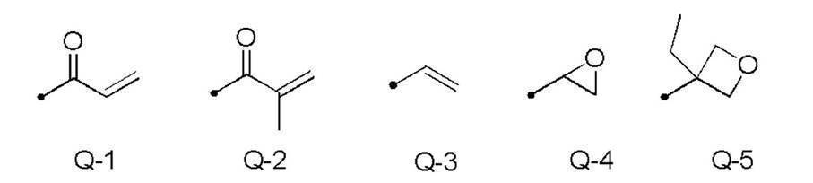
フェニレン基およびトランス-1,4-シクロヘキシレン基について「置換基を有していてもよい」というときの置換基は、特に限定されず、例えば、アルキル基、シクロアルキル基、アルコキシ基、アルキルエーテル基、アミド基、アミノ基、およびハロゲン原子ならびに、上述の置換基を2つ以上組み合わせて構成される基からなる群から選択される置換基が挙げられる。また、置換基の例としては、後述の-C(=O)-X3-Sp3-Q3で表される置換基が挙げられる。フェニレン基およびトランス-1,4-シクロヘキシレン基は、置換基を1~4個有していてもよい。2個以上の置換基を有するとき、2個以上の置換基は互いに同一であっても異なっていてもよい。
重合性基としては、アクリロイル基(式Q-1)またはメタクリロイル基(式Q-2)が好ましい。
キラル剤はコレステリック液晶相の螺旋構造を誘起する機能を有する。キラル化合物は、化合物によって誘起する螺旋のセンスまたは螺旋ピッチが異なるため、目的に応じて選択すればよい。
キラル剤としては、特に制限はなく、公知の化合物を用いることができる。キラル剤の例としては、液晶デバイスハンドブック(第3章4-3項、TN、STN用カイラル剤、199頁、日本学術振興会第142委員会編、1989)、特開2003-287623号、特開2002-302487号、特開2002-080478号、特開2002-080851号、特開2010-181852号、および、特開2014-034581号等の各公報に記載の化合物が挙げられる。
キラル剤は、重合性基を有していてもよい。キラル剤と液晶化合物とがいずれも重合性基を有する場合は、重合性キラル剤と重合性液晶化合物との重合反応により、重合性液晶化合物から誘導される繰り返し単位と、キラル剤から誘導される繰り返し単位とを有するポリマーを形成することができる。この態様では、重合性キラル剤が有する重合性基は、重合性液晶化合物が有する重合性基と、同種の基であることが好ましい。従って、キラル剤の重合性基も、不飽和重合性基、エポキシ基またはアジリジニル基であることが好ましく、不飽和重合性基であることがさらに好ましく、エチレン性不飽和重合性基であることが特に好ましい。
また、キラル剤は、液晶化合物であってもよい。
液晶組成物における、キラル剤の含有量は、重合性液晶化合物量の0.01~200モル%が好ましく、1~30モル%がより好ましい。なお、液晶組成物中におけるキラル剤の含有量は、組成物中の全固形分に対するキラル剤の濃度(質量%)を意図する。
液晶組成物は、重合開始剤を含有していることが好ましい。紫外線照射により重合反応を進行させる態様では、使用する重合開始剤は、紫外線照射によって重合反応を開始可能な光重合開始剤であることが好ましい。
光重合開始剤の例には、α-カルボニル化合物(米国特許第2367661号、米国特許第2367670号の各明細書記載)、アシロインエーテル(米国特許第2448828号明細書記載)、α-炭化水素置換芳香族アシロイン化合物(米国特許第2722512号明細書記載)、多核キノン化合物(米国特許第3046127号、米国特許第2951758号の各明細書記載)、トリアリールイミダゾールダイマーとp-アミノフェニルケトンとの組み合わせ(米国特許第3549367号明細書記載)、アクリジンおよびフェナジン化合物(特開昭60-105667号公報、米国特許第4239850号明細書記載)、アシルフォスフィンオキシド化合物(特公昭63-040799号公報、特公平5-029234号公報、特開平10-095788号公報、特開平10-029997号公報、特開2001-233842号公報、特開2000-080068号公報、特開2006-342166号公報、特開2013-114249号公報、特開2014-137466号公報、特許4223071号公報、特開2010-262028号公報、特表2014-500852号公報記載)、オキシム化合物(特開2000-066385号公報、特許第4454067号公報記載)、および、オキサジアゾール化合物(米国特許第4212970号明細書記載)等が挙げられる。例えば、特開2012-208494号公報の段落0500~0547の記載も参酌できる。
アシルフォスフィンオキシド化合物としては、例えば、市販品のBASFジャパン(株)製のIRGACURE810(化合物名:ビス(2,4,6-トリメチルベンゾイル)-フェニルフォスフィンオキサイド)を用いることができる。オキシム化合物としては、IRGACURE OXE01(BASF社製)、IRGACURE OXE02(BASF社製)、TR-PBG-304(常州強力電子新材料有限公司製)、ならびに、アデカアークルズNCI-831およびアデカアークルズNCI-930(ADEKA社製)等の市販品を用いることができる。
重合開始剤は、1種のみ用いてもよいし、2種以上を併用してもよい。
液晶組成物中の光重合開始剤の含有量は、重合性液晶化合物の含有量に対して0.1~20質量%が好ましく、0.5~5質量%がより好ましい。
液晶組成物は、硬化後の膜強度向上、耐久性向上のため、任意に架橋剤を含有していてもよい。架橋剤としては、紫外線、熱、湿気等で硬化するものが好適に使用できる。
架橋剤としては、特に制限はなく、目的に応じて適宜選択することができる。架橋剤としては、例えば、トリメチロールプロパントリ(メタ)アクリレート、ペンタエリスリトールトリ(メタ)アクリレート等の多官能アクリレート化合物;グリシジル(メタ)アクリレート、エチレングリコールジグリシジルエーテル等のエポキシ化合物;2,2-ビスヒドロキシメチルブタノール-トリス[3-(1-アジリジニル)プロピオネート]、4,4-ビス(エチレンイミノカルボニルアミノ)ジフェニルメタン等のアジリジン化合物;ヘキサメチレンジイソシアネート、ビウレット型イソシアネート等のイソシアネート化合物;オキサゾリン基を側鎖に有するポリオキサゾリン化合物;ビニルトリメトキシシラン、N-(2-アミノエチル)3-アミノプロピルトリメトキシシラン等のアルコキシシラン化合物等が挙げられる。また、架橋剤の反応性に応じて公知の触媒を用いることができ、膜強度および耐久性向上に加えて生産性を向上させることができる。これらは、1種単独で使用してもよいし、2種以上を併用してもよい。
架橋剤の含有量は、3~20質量%が好ましく、5~15質量%がより好ましい。架橋剤の含有量を3質量%以上とすることにより、架橋密度向上の効果を得ることができ、架橋剤の含有量を20質量%以下とすることにより、コレステリック液晶層の安定性の低下を防止できる。
なお、「(メタ)アクリレート」は、「アクリレートおよびメタクリレートのいずれか一方または双方」の意味で使用される。
液晶組成物中には、安定的にまたは迅速にプレーナー配向のコレステリック液晶層とするために寄与する配向制御剤を添加してもよい。配向制御剤の例としては、特開2007-272185号公報の段落[0018]~[0043]等に記載のフッ素(メタ)アクリレート系ポリマー、特開2012-203237号公報の段落[0031]~[0034]等に記載の式(I)~(IV)で表される化合物、および、特開2013-113913号公報に記載の化合物等が挙げられる。
なお、配向制御剤としては1種を単独で用いてもよいし、2種以上を併用してもよい。
その他、液晶組成物は、塗膜の表面張力を調整し厚さを均一にするための界面活性剤、および重合性モノマー等の種々の添加剤から選ばれる少なくとも1種を含有していてもよい。また、液晶組成物中には、必要に応じて、さらに重合禁止剤、酸化防止剤、紫外線吸収剤、光安定化剤、色材、および、金属酸化物微粒子等を、光学性能を低下させない範囲で添加することができる。
なお、複数のコレステリック液晶層からなる積層膜は、コレステリック液晶層の上述の製造工程を繰り返し行うことにより形成することができる。
液晶組成物の調製に使用する溶媒には、特に制限はなく、目的に応じて適宜選択することができるが、有機溶媒が好ましく用いられる。
有機溶媒には、特に制限はなく、目的に応じて適宜選択することができ、例えば、ケトン類、アルキルハライド類、アミド類、スルホキシド類、ヘテロ環化合物、炭化水素類、エステル類、および、エーテル類等が挙げられる。これらは、1種単独で使用してもよいし、2種以上を併用してもよい。これらの中でも、環境への負荷を考慮した場合にはケトン類が特に好ましい。
支持体、配向膜、下層となるコレステリック液晶層等への液晶組成物の塗布方法には、特に制限はなく、目的に応じて適宜選択することができる。塗布方法としては、例えば、ワイヤーバーコーティング法、カーテンコーティング法、押し出しコーティング法、ダイレクトグラビアコーティング法、リバースグラビアコーティング法、ダイコーティング法、スピンコーティング法、ディップコーティング法、スプレーコーティング法、および、スライドコーティング法等が挙げられる。また、別途支持体上に塗設した液晶組成物を転写することによっても実施できる。
塗布した液晶組成物を加熱することにより、液晶分子を配向させる。加熱温度は、200℃以下が好ましく、130℃以下がより好ましい。この配向処理により、重合性液晶化合物が、フィルム面に対して実質的に垂直な方向に螺旋軸を有するようにねじれ配向している光学薄膜が得られる。
光重合反応を促進するため、加熱条件下または窒素雰囲気下で光照射を実施してもよい。照射紫外線波長は350~430nmが好ましい。重合反応率は安定性の観点から、高いほうが好ましく70%以上が好ましく、80%以上がより好ましい。重合反応率は、重合性の官能基の消費割合を赤外線吸収スペクトルの測定により、決定することができる。
本発明のプロジェクター10を構成する反射部材16は、選択反射層として、直線偏光反射層を用いてもよい。
直線偏光反射層としては、例えば、屈折率異方性の異なる薄膜を積層した偏光板が挙げられる。このような偏光板は、コレステリック液晶層と同様に高い可視光線透過率であり、HUDにおける使用時に斜めから入射する投映光を視感度の高い波長において反射することができる。
直線偏光反射層の厚さは、1.0~50μmが好ましく、2.0~30μmがより好ましい。
選択反射層46は、入射角45°で入射した光の反射光の半値幅(半値全幅)が、70nm以下であるのが好ましく、50nm以下であるのがより好ましく、30nm以下であるのがさらに好ましい。
選択反射層46による反射光の半値幅を70nm以下とすることにより、選択反射層46(反射部材16)が、上述のように侵入した太陽光のうち、投映光となる光ビームの近傍以外の波長域の可視光も透過する。これにより、可視光による中間像スクリーン14、光偏向器36および偏光板34等の熱損傷を、より好適に防止できる。
反射部材16は、図1に示すように偏光変換層48を有する。
図示例においては、好ましい態様として、偏光変換層48は、干渉抑制層50と選択反射層46との間に配置されるが、本発明は、これに制限はされない。例えば、偏光変換層48は、干渉抑制層50の表面に設けてもよい。
これに対応して、偏光変換層48は、直線偏光を円偏光に変換するものである。具体的には、偏光変換層48は、干渉抑制層50を透過したp偏光を、コレステリック液晶層が反射する旋回方向の円偏光に変換して透過させ、コレステリック液晶層で反射された円偏光を、再度、p偏光に変換して、干渉抑制層50に入射、透過させる。なお、この場合の円偏光とは、真円の円偏光のみならず、楕円偏光も含む。
従って、偏光変換層48は、選択反射層46よりも画像形成部12からの投映光の入射側に設けられる。
あるいは、偏光変換層48は、3λ/4位相差層も利用可能である。
この際には、位相差層は、コレステリック液晶層が反射する円偏光の旋回方向に応じて、p偏光をコレステリック液晶層が反射する旋回方向の円偏光に変換するように、遅相軸の位置を設定して配置される。
偏光変換層48としては、例えば、延伸されたポリカーボネートフィルム、延伸されたノルボルネン系ポリマーフィルム、炭酸ストロンチウムのような複屈折を有する無機粒子を含有して配向させた透明フィルム、支持体上に無機誘電体を斜め蒸着した薄膜、重合性液晶化合物を一軸配向させて配向固定したフィルム、および、液晶化合物を一軸配向させて配向固定したフィルム等が挙げられる。
このような偏光変換層48は、一例として、仮支持体、または配向膜表面に、重合性液晶化合物を含む液晶組成物を塗布し、そこで液晶組成物中の重合性液晶化合物を液晶状態においてネマチック配向に形成後、硬化によって固定化して、形成することができる。
この場合の偏光変換層48の形成は、液晶組成物中にキラル剤を添加しない以外は、上述のコレステリック液晶層の形成と同様に行うことができる。ただし、液晶組成物の塗布後のネマチック配向の際、加熱温度は50~120℃が好ましく、60~100℃がより好ましい。
反射部材16は、偏光変換層48の上に、厚さが10μm以上の干渉抑制層50を有する。
本発明のプロジェクター10は、コールドミラーとして作用する反射部材16が、選択反射層46よりも画像形成部12からの投映光の入射側に、このような干渉抑制層50を有することにより、光源30が出射する光ビームの波長が変動した場合であっても、投映像の輝度低下および投映像の色バランスの崩れが生じることを防止している。
そのため、コレステリック液晶層を有する反射部材を用いることにより、通常のコールドミラーを用いた場合より、プロジェクターに侵入して、投映光と逆に進行する太陽光による加熱に起因する中間像スクリーンおよび偏光板等の劣化を防止できる。
本発明者は、この原因について検討した。その結果、コレステリック液晶層が薄いため、コレステリック液晶層が反射した光が、上層(光入出射側)のコレステリック液晶層の内部で干渉してしまい、コレステリック液晶層の反射波長特性が、最大反射波長の近傍で大きく変動することに起因することを見出した。
また、光源30が出射した光ビームすなわち投映光は、青色反射コレステリック液晶層46B側から入射する。
これに対して、図4に概念的に示すように、緑色の光ビームLgは、青色反射コレステリック液晶層46Bを透過して、緑色反射コレステリック液晶層46Gによって反射される。反射された光ビームLgは、青色反射コレステリック液晶層46Bを透過しようとする。しかしながら、青色反射コレステリック液晶層46Bが薄いので、一部の光ビームLgは、青色反射コレステリック液晶層46Bと空気界面との屈折率の差に起因して、図4に破線で示すように、青色反射コレステリック液晶層46Bの内部で干渉してしまう。
また、図5に概念的に示すように、赤色の光ビームLrは、青色反射コレステリック液晶層46Bおよび緑色反射コレステリック液晶層46Gを透過して、赤色反射コレステリック液晶層46Rによって反射される。反射された光ビームLrは、緑色反射コレステリック液晶層46Gおよび青色反射コレステリック液晶層46Bを透過しようとする。しかしながら、緑色反射コレステリック液晶層46Gおよび青色反射コレステリック液晶層46Bが薄いので、同様に、一部の光ビームLrは、青色反射コレステリック液晶層46Bと空気界面との屈折率の差に起因して、図5に破線で示すように、緑色反射コレステリック液晶層46Gおよび、青色反射コレステリック液晶層46Bの内部で干渉してしまう。
なお、このような干渉は、青色反射コレステリック液晶層46Bの上に偏光変換層48が有る場合、偏光変換層48の中でも生じる。
すなわち、光ビームの入射側に、他のコレステリック液晶層を有するコレステリック液晶層は、選択反射中心波長の近傍における、反射率の波長依存性が高くなる。この反射率の波長依存性は、光ビームの半値幅が小さいほど大きい。特に、半値幅が20nm以下の光ビームでは、波長変動による反射率の変動が大きい。
その結果、G光源30GおよびR光源30Rの発熱によって、緑色の光ビームLgおよび赤色の光ビームLr(投映光)の波長が変動すると、赤色反射コレステリック液晶層46Rおよび緑色反射コレステリック液晶層46Gによる反射率が低下してしまい、投映像の輝度の低下および色バランスの崩れが生じてしまう。
干渉抑制層50の屈折率(樹脂の屈折率)は、コレステリック液晶層と近い。そのため、図6に概念的に示すように、青色の光ビームLbは、入射面側の青色反射コレステリック液晶層46Bによって反射され、干渉抑制層50を透過して出射される。
反射された光ビームLgは、青色反射コレステリック液晶層46Bに侵入するが、青色反射コレステリック液晶層46Bの上に、屈折率が近い干渉抑制層50が有るので、青色反射コレステリック液晶層46Bを透過して、干渉抑制層50に侵入する。また、干渉抑制層50は、十分な厚さを有するので、干渉抑制層50と空気界面との屈折率の差が大きくても、干渉抑制層50内部での干渉は生じずに、図7に示すように、光ビームLgは、干渉抑制層50を透過して出射される。
反射された光ビームLrは、緑色反射コレステリック液晶層46Gを透過して青色反射コレステリック液晶層46Bに侵入するが、青色反射コレステリック液晶層46Bの上に、屈折率が近い干渉抑制層50が有るので、青色反射コレステリック液晶層46Bを透過して、干渉抑制層50に侵入する。また、干渉抑制層50は、十分な厚さを有するので、干渉抑制層50と空気界面との屈折率の差が大きくても、干渉抑制層50内部での干渉は生じずに、図8に示すように、光ビームLrは、干渉抑制層50を透過して出射される。
そのため、選択反射層46に対して投映光の入射側に干渉抑制層50を有する反射部材16を用いる本発明のプロジェクター10によれば、G光源30GおよびR光源30Rの発熱によって、緑色の光ビームLgおよび赤色の光ビームLrの波長が変動しても、反射率の変動が生じず、高輝度で色バランスの投光な投映像を、安定して投映できる。
また、円偏光を選択的に反射する選択反射層46に変えて、直線偏光反射層を用いた場合にも、同様の現象を生じる。
干渉抑制層50の厚さが10μm未満では、光の干渉を十分に抑制できず、光ビーム(投映光)の波長変動によって、輝度の低下および色バランスの崩れ等を生じてしまう。
ここで、コレステリック液晶層内における干渉の発生を防止するための干渉抑制層50は、光ビームの半値幅が狭いほど、厚くする必要がある。また、コレステリック液晶層内における干渉の発生を防止するための干渉抑制層50の厚さは、光ビームの波長が長いほど、厚くする必要がある。すなわち、光ビームの半値幅が狭いほど、また、光ビームの波長が長いほど、コレステリック液晶層内における干渉が発生し易く、波長変動に起因する反射率の低下が生じやすい。
例えば、半値幅が10nmの光ビームの場合、450nmの光ビームの干渉を防止するためには、干渉抑制層50の厚さは20μm以上とするのが好ましい。また、半値幅が10nmの光ビームの場合、532nmの光ビームの干渉を防止するためには、干渉抑制層50の厚さは28μm以上とするのが好ましい。さらに、半値幅が10nmの光ビームの場合、633nmの光ビームの干渉を防止するためには、干渉抑制層50の厚さは40μm以上とするのが好ましい。
この点を考慮すると、干渉抑制層50の厚さは、40μm以上が好ましく、80μm以上がより好ましく、100μm以上がさらに好ましく、400μm以上が特に好ましい。
反射部材16が不要に厚くなることを防止できる、反射部材16が曲率を持つ時に転写しやすくなることを防止できる等の点で、干渉抑制層50の厚さは、2.0mm以下が好ましく、1.0mm以下がより好ましい。
干渉抑制層50の可視光線透過率は、80%以上が好ましく、85%以上がより好ましく、90%以上がさらに好ましい。
干渉抑制層50の可視光線透過率を80%以上とすることにより、高輝度の投映像を投映できる、反射時の損失が少なく高輝度の投映像を投影できる等の点で好ましい。
干渉抑制層50の面内レタデーションReは、10nm以下が好ましく、5nm以下がより好ましく、2nm以下がさらに好ましい。
干渉抑制層50の面内レタデーションReを10nm以下とすることにより、干渉抑制層50によって投映光の偏光が崩れることを防止できる、直線偏光が入射した場合の干渉が減少する等の点で好ましい。
干渉抑制層50の屈折率は、1.45~1.6が好ましく、1.5~1.58がより好ましく、1.52~1.56さらに好ましい。
干渉抑制層50の屈折率を1.45~1.6とすることにより、干渉抑制層50の屈折率にも、制限はないが、コレステリック液晶層(選択反射層)との屈折率の差を十分に小さくして、干渉抑制層50とコレステリック液晶層との界面での光の反射を防止できる等の点で好ましい。
一例として、TAC、COP、PMMA、ポリカーボネート(PC)およびPET等の樹脂材料、ガラス、ならびに、アクリル板等が例示される。
中でも、TAC、COPおよびPMMA等は好適に利用される。
反射部材は、コレステリック液晶層または位相差層の形成の際に液晶組成物が塗布される下層として、配向膜を含んでいてもよい。
配向膜は、ポリマーなどの有機化合物(例えば、ポリイミド、ポリビニルアルコール、ポリエステル、ポリアリレート、ポリアミドイミド、ポリエーテルイミド、ポリアミドおよび変性ポリアミドなどの樹脂)のラビング処理、無機化合物の斜方蒸着、マイクログルーブを有する層の形成、ならびに、ラングミュア・ブロジェット法(LB膜)を用いた有機化合物(例えば、ω-トリコサン酸、ジオクタデシルメチルアンモニウムクロライドおよびステアリル酸メチル)の累積等の手段で、設けることができる。さらに、電場の付与、磁場の付与または光照射により、配向機能が生じる配向膜を用いてもよい。
特にポリマーからなる配向膜はラビング処理を行ったうえで、ラビング処理面に液晶組成物を塗布することが好ましい。ラビング処理は、ポリマー層の表面を、紙、布で一定方向に、擦ることにより実施することができる。
配向膜を設けずに、干渉抑制層50をラビング処理した表面に、液晶組成物を塗布してもよい。すなわち、干渉抑制層50を配向膜として作用させてもよい。
配向膜の厚みには制限はないが、0.01~5.0μmが好ましく、0.05~2.0μmがより好ましい。
なお、仮支持体を用いて選択反射層等を有する反射部材を作製する場合は、配向層は仮支持体とともに剥離してもよい。すなわち、配向膜は、反射部材の作製時のみに存在し、反射部材が完成した時点では、反射部材を構成する層とはならなくてもよい。
一例として、干渉抑制層50となる樹脂フィルム等の表面に配向膜となる膜を形成し、ラビング処理等によって配向膜を形成する。次いで、配向膜に偏光変換層48を形成し、偏光変換層の表面にコレステリック液晶層等の選択反射層46を形成する。干渉抑制層50(配向膜)、偏光変換層48および選択反射層を有する積層体を、OCA等の接着層42によって、選択反射層46を向けてガラス板等の基板40に貼着することで、反射部材16を完成する。
または、仮支持体に配向膜および偏光変換層48を形成した後、仮支持体を剥離して、OCA等の接着層によって、基板40および干渉抑制層50を形成してもよい。
反射部材16は、必用に応じて、干渉抑制層50の上(選択反射層46の逆面)に、耐擦傷性を向上するために、ハードコート層を有してもよい。
ハードコート層は、ハードコート層形成用組成物を用いて形成するのが好ましい。
ハードコート層形成用組成物は、分子内に3個以上のエチレン性不飽和二重結合基を有する化合物を含むのが好ましい。
エチレン性不飽和二重結合基としては、(メタ)アクリロイル基、ビニル基、スチリル基、および、アリル基等の重合性官能基が挙げられ、中でも、(メタ)アクリロイル基、および、-C(O)OCH=CH2が好ましく、より好ましくは(メタ)アクリロイル基である。エチレン性不飽和二重結合基を有する事によって、高い硬度を維持する事ができ、耐湿熱性も付与する事ができる。さらに、分子内に3個以上のエチレン性不飽和二重結合基を有する事によって、より高い硬度を発現できる。
3個以上の(メタ)アクリロイル基を有する多官能アクリレート系化合物類の具体化合物としては、日本化薬社製のKAYARAD DPHA、同DPHA-2C、同PET-30、同TMPTA、同TPA-320、同TPA-330、同RP-1040、同T-1420、同D-310、同DPCA-20、同DPCA-30、同DPCA-60および同GPO-303、ならびに、大阪有機化学工業社製のV#400およびV#36095D等のポリオールと(メタ)アクリル酸のエステル化物を挙げることができる。
また、紫光UV-1400B、同UV-1700B、同UV-6300B、同UV-7550B、同UV-7600B、同UV-7605B、同UV-7610B、同UV-7620EA、同UV-7630B、同UV-7640B、同UV-6630B、同UV-7000B、同UV-7510B、同UV-7461TE、同UV-3000B、同UV-3200B、同UV-3210EA、同UV-3310EA、同UV-3310B、同UV-3500BA、同UV-3520TL、同UV-3700B、同UV-6100B、同UV-6640B、同UV-2000B、同UV-2010B、同UV-2250EAおよび同UV-2750B(以上、日本合成化学社製)、UL-503LN(共栄社化学社製)、ユニディック17-806、同17-813、同V-4030および同V-4000BA(以上、大日本インキ化学工業社製)、EB-1290K、EB-220、EB-5129、EB-1830およびEB-4358(以上、ダイセルUCB社製)、ハイコープAU-2010および同AU-2020(以上、トクシキ社製)、アロニックスM-1960(東亜合成社製)、ならびに、アートレジンUN-3320HA,UN-3320HC,UN-3320HS、UN-904およびHDP-4Tなどの3官能以上のウレタンアクリレート化合物、アロニックスM-8100、M-8030およびM-9050(以上、東亞合成社製)、ならびに、KBM-8307(ダイセルサイテック社製)などの3官能以上のポリエステル化合物なども好適に使用することができる。
また、分子内に3個以上のエチレン性不飽和二重結合基を有する化合物は単一の化合物から構成しても良いし、複数の化合物を組み合わせて用いる事もできる。
ハードコート層は、干渉抑制層50の表面に、上述したハードコート層形成用組成物を塗布して、乾燥、硬化させることで形成できる。
ハードコート層は以下の塗布方法により形成することができるが、この方法に制限されない。塗布方法としては、ディップコート法、エアーナイフコート法、カーテンコート法、ローラーコート法、ワイヤーバーコート法、グラビアコート法、スライドコート法、エクストルージョンコート法(ダイコート法)(特開2003-164788号公報参照)、および、マイクログラビアコート法等の公知の方法が用いられる。その中でもマイクログラビアコート法、および、ダイコート法が好ましい。
本発明において、ハードコート層など塗布により層形成する場合の、乾燥、硬化方法に関して、好ましい例を以下に述べる。
本発明では、電離放射線による照射と、照射の前、照射と同時または照射後の熱処理とを組み合わせることにより、硬化することが有効である。
以下に、いくつかの製造工程のパターンを示すが、これらに制限はされない。なお、以下の例において、「-」は熱処理を行っていないことを示す。
(1)熱処理 → 電離放射線硬化 → -
(2)熱処理 → 電離放射線硬化 → 熱処理
(3) - → 電離放射線硬化 → 熱処理
例えば、塗膜が紫外線硬化性であれば、紫外線ランプによって10~1000mJ/cm2の照射量の紫外線を照射して各層を硬化するのが好ましい。照射の際には、上述のエネルギーの紫外線を一度に当ててもよいし、分割して照射することもできる。特に塗膜の面内での性能ばらつきを少なくでき、さらに、カールを良化させるという観点からは、2回以上に分割して紫外線を照射するのが好ましい。具体的には、初期に150mJ/cm2以下の低照射量の紫外光を照射し、その後、50mJ/cm2以上の高照射量の紫外光を照射し、かつ、初期よりも後期の方で高い照射量の紫外線を当てるのが好ましい。
上述したように、本発明のプロジェクター10は、コールドミラーの作用を発現する反射部材16が干渉抑制層50を有するので、反射部材16による反射率の波長依存性が小さい。そのため、本発明によれば、発熱によって光ビームの波長が変動しても、反射部材16による反射率の変動が生じず、高輝度で色バランスの投光な投映像を、安定して投映できる。
なお、ウインドシールドガラス26は、車および電車等の車両、飛行機、船舶、二輪車、ならびに、遊具等の乗り物一般の窓ガラスおよび風防ガラスを意味する。
なお、板ガラス64は、ウインドシールドガラスに用いられる公知の板ガラスで、平板状でも、曲面状でも、平面と曲面との両方を有するものでもよい。中間膜62も、ポリビニルブチラールおよびエチレン-酢酸ビニル共重合体等、ウインドシールド用の合わせガラスにおいて中間膜として用いられる公知のものが利用可能である。
p偏光を反射するハーフミラーフィルム60としては、上述したコレステリック液晶層と同様の、赤色光を選択的に反射するコレステリック液晶層、緑色光を選択的に反射するコレステリック液晶層、および、青色光を選択的に反射するコレステリック液晶層との3層のコレステリック液晶層と、λ/4位相差層とを有し、λ/4位相差層を投映光の入射側にするハーフミラーフィルム60が例示される。
また、λ/4位相差層は、コレステリック液晶層が反射する円偏光に応じて、入射するp偏光をコレステリック液晶層が反射する旋回方向の円偏光に変換するように、遅相軸の向きを設定される。
これにより、ハーフミラーフィルム60は、p偏光の投映光を反射する。
しかしながら、偏光サングラスを用いた投映像の観察が可能である、ウインドシールドガラスを楔形にする必要が無い等の点で、本発明のプロジェクターは、p偏光の投映光を投映するのが好ましい。
(狭帯域コレステリック液晶層形成用組成物1、2および3)
下記の成分を混合して、入射角45°で選択反射中心波長が450nmである狭帯域コレステリック液晶層を形成する狭帯域コレステリック液晶層形成用組成物1、入射角45°で選択反射中心波長が530nmである狭帯域コレステリック液晶層を形成する狭帯域コレステリック液晶層形成用組成物2、および、入射角45°で選択反射中心波長が630nmである狭帯域コレステリック液晶層を形成する狭帯域コレステリック液晶層形成用組成物3を調製した。
―――――――――――――――――――――――――――――――――
狭帯域コレステリック液晶層形成用組成物1、2および3
―――――――――――――――――――――――――――――――――
・棒状液晶化合物101 55質量部
・棒状液晶化合物102 30質量部
・棒状液晶化合物201 13質量部
・棒状液晶化合物202 2質量部
・重合開始剤IRGACURE OXE01(BASF社製)
1.0質量部
・配向制御剤1(フッ素系水平配向剤1) 0.01質量部
・配向制御剤2(フッ素系水平配向剤2) 0.01質量部
・右旋回性キラル剤LC756(BASF社製)
目標の選択反射中心波長に合わせて調整
・溶媒(メチルエチルケトン) 溶質濃度が20質量%となる量
―――――――――――――――――――――――――――――――――


狭帯域コレステリック液晶層形成用組成物1~3を用いて、以下に示す反射部材の作製時と同様に仮支持体上に膜厚4μmの単一層の狭帯域コレステリック液晶層を作製し、可視域光の反射特性を確認した。その結果、作製した狭帯域コレステリック液晶層は、全て右円偏光反射層であり、入射角45°における選択反射中心波長は、狭帯域コレステリック液晶層形成用組成物1が450nm、狭帯域コレステリック液晶層形成用組成物2が530nm、狭帯域コレステリック液晶層形成用組成物3が630nmであった。
下記の成分を混合し、下記組成の位相差層形成用組成物を調製した。
―――――――――――――――――――――――――――――――――
位相差層形成用組成物
―――――――――――――――――――――――――――――――――
・混合物1 100質量部
・配向制御剤1 0.05質量部
・配向制御剤3(フッ素系水平配向剤3) 0.01質量部
・重合開始剤IRGACURE OXE01(BASF社製)
1.0質量部
・溶媒(メチルエチルケトン) 溶質濃度が30質量%となる量
―――――――――――――――――――――――――――――――――
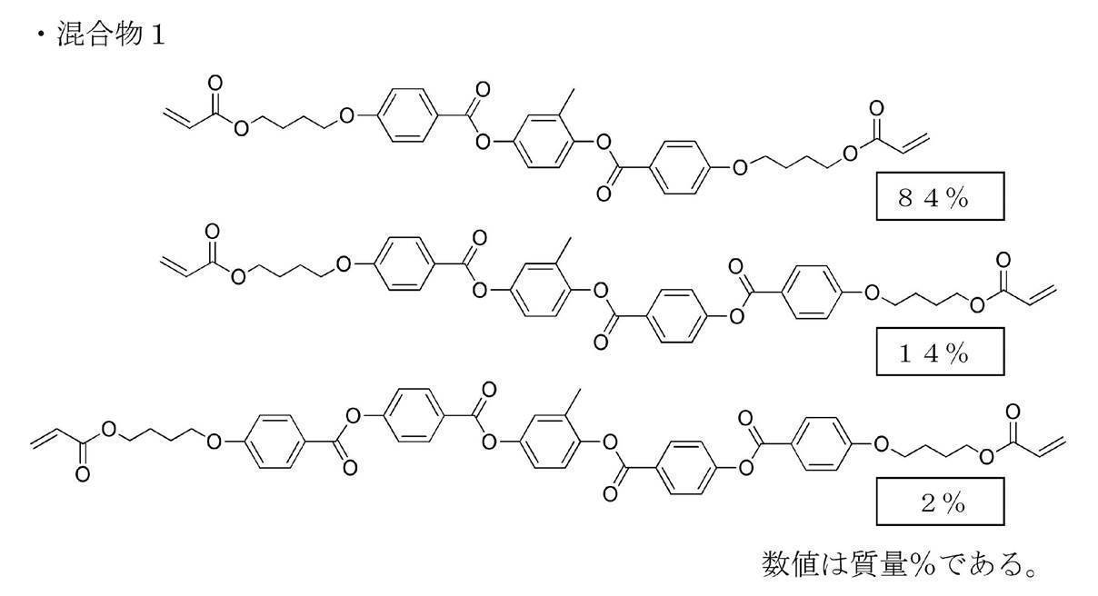

<<反射部材の作製>>
<セルロースアシレートフィルムの鹸化>
国際公開第2014/112575号の実施例20と同一の作製方法で得られた40μmセルロースアシレートフィルム(TACフィルム)を、温度60℃の誘電式加熱ロールを通過させ、フィルム表面温度を40℃に昇温した後に、フィルムの片面に下記に示す組成のアルカリ溶液を、バーコーターを用いて塗布量14mL/m2で塗布し、110℃に加熱したスチーム式遠赤外ヒーター(ノリタケカンパニーリミテド社製)の下に10秒間滞留させた。
次いで、同じくバーコーターを用いて、純水を3mL/m2塗布した。
次いで、ファウンテンコーターによる水洗とエアナイフによる水切りを3回繰り返した後に、70℃の乾燥ゾーンに5秒間滞留させて乾燥し、鹸化処理したセルロースアシレートフィルム1を作製した。
セルロースアシレートフィルム1の屈折率を位相差測定装置(王子計測機器社製、KOBRA-WPR)によって測定したところ、1.49であった。また、セルロースアシレートフィルム1の面内レタデーションReをAxoScanで測定したところ、2nmであった。
アルカリ溶液
―――――――――――――――――――――――――――――――――
・水酸化カリウム 4.7質量部
・水 15.7質量部
・イソプロパノール 64.8質量部
・界面活性剤(C16H33O(CH2CH2O)10H) 1.0質量部
・プロピレングリコール 14.9質量部
―――――――――――――――――――――――――――――――――
鹸化処理したセルロースアシレートフィルム1(透明支持体)の鹸化処理面に、下記に示す組成の配向膜形成用組成物を、ワイヤーバーコーターで24mL/m2塗布し、100℃の温風で120秒乾燥した。
配向膜形成用組成物の組成
―――――――――――――――――――――――――――――――――
・変性ポリビニルアルコール 28質量部
・クエン酸エステル(AS3、三共化学社製) 1.2質量部
・光開始剤(イルガキュア2959、BASF社製) 0.84質量部
・グルタルアルデヒド 2.8質量部
・水 699質量部
・メタノール 226質量部
―――――――――――――――――――――――――――――――――

配向膜を形成したセルロースアシレートフィルム1の配向膜の表面に、図9に概念的に示すように、配向膜面から見て、セルロースアシレートフィルム1の長手方向を基準に時計回りに45°回転させた方向にラビング処理(レーヨン布、圧力:0.1kgf(0.98N)、回転数:1000rpm(revolutions per minute)、搬送速度:10m/min、回数:1往復)を施した。
図9において、Hはセルロースアシレートフィルム1の長手方向、角度αは45°、Saはラビング処理の方向である。
位相差層の面内レタデーションReをAxoScan(アクソメトリクス社製)を用いて測定したところ、142nmであった。
形成した位相差層の表面に、狭帯域コレステリック液晶層形成用組成物1を乾燥後の乾膜の厚さが4μmになるようにワイヤーバーを用いて室温にて塗布して塗布層を得た。塗布層を室温にて30秒間乾燥させた後、85℃の雰囲気で2分間加熱し、その後、酸素濃度1000ppm以下の環境にて60℃でフュージョン製Dバルブ(90mW/cm2のランプ)にて出力60%で6~12秒間UV(ultraviolet)照射し、コレステリック液晶相を固定して、厚さ4μmの狭帯域コレステリック液晶層を得た。
次に、得られたコレステリック液晶層の表面にさらに狭帯域コレステリック液晶層形成用組成物2を用いて同様の工程を繰り返し、厚さ4μmの狭帯域コレステリック液晶層を得た。
次に、得られたコレステリック液晶層の表面にさらに狭帯域コレステリック液晶層形成用組成物3を用いて同様の工程を繰り返し、厚さ4μmの狭帯域コレステリック液晶層を得た。
積層体Aの反射スペクトルを、分光光度計(日本分光株式会社製、V-670)で測定した。その結果、入射角45°において、波長450nm、波長530nm、および、波長630nmに選択反射中心波長を有する反射スペクトルが得られた。
その結果、入射角45°における青色光の反射光の半値幅は33nm、緑色光の反射光の半値幅は40nm、赤色光の反射光の半値幅は46nmであった。
これにより、ガラス/OCA/狭帯域コレステリック液晶層/λ/4層/干渉抑制層(TAC)の層構成を有する反射部材を作製した。
偏光変換層としての位相差層(λ/4層)を形成しない以外には、実施例1と同様にして、反射部材を作製した。作製した反射部材の層構成は、以下のとおりである。
ガラス/OCA/狭帯域コレステリック液晶層/干渉抑制層(TAC)
(旋光層形成用組成物)
下記の成分を混合し、下記組成の旋光層形成用組成物を調製した。
―――――――――――――――――――――――――――――――――
旋光層形成用組成物
―――――――――――――――――――――――――――――――――
・混合物1 100質量部
・配向制御剤1 0.05質量部
・配向制御剤3 0.02質量部
・右旋回性キラル剤LC756(BASF社製) 1.69質量部
・重合開始剤IRGACURE OXE01(BASF社製)
1.0質量部
・溶媒(メチルエチルケトン) 溶質濃度が20質量%となる量
―――――――――――――――――――――――――――――――――
なお、螺旋構造の膜厚dは『螺旋構造のピッチP×ピッチ数』で表せる。上述のように、螺旋構造のピッチPとは、螺旋構造における1ピッチの長さである。また、コレステリック液用層では、選択反射中心波長λは『1ピッチの長さP×面内の平均屈折率n』と一致する(λ=P×n)。従って、ピッチPは『選択反射中心波長λ/面内の平均屈折率n』となる(P=λ/n)。
このことから、コレステリック液晶層とした場合に、選択反射中心波長λが1550nmとなるように、偏光変換層形成用組成物を調製し、ピッチ数が0.7となるように、塗膜の膜厚を0.7μmとした。
作製した反射部材の層構成は、以下のとおりである。
ガラス/OCA/狭帯域コレステリック液晶層/旋光層/干渉抑制層(TAC)
特表平9-506837号公報に記載された方法に基づいて、選択反射中心波長が、入射角45°で波長450nm、波長530nm、および、波長630nmとなり、反射率が40%になるように、2,6-ポリエチレンナフタレート(PEN)とナフタレート70/テレフタレート30のコポリエステル(coPEN)とを、各層の厚さを調整して形成することで、直線偏光反射板を作製した。
なお、直線偏光反射板は、反射光を狭帯域とするため、PENとcoPENの平均屈折率差が0.1程度になる様に調整した。
セルロースアシレートフィルム1に、λ/4層およびコレステリック液晶層を形成せず、OCAを用いて直線偏光反射板を貼着した以外は、実施例1と同様にして、反射部材を作製した。作製した反射部材の層構成は以下のとおりである。
ガラス/OCA/狭帯域直線偏光反射板/OCA/干渉抑制層(TAC)
<ハードコート層組成物の調製>
下記の組成となるように、各成分を混合し、固形分濃度が約51質量%となるハードコート層組成物を作製した。
――――――――――――――――――――――――――――――――――
ハードコート層組成物
――――――――――――――――――――――――――――――――――
・ジペンタエリスリトールポリアクリレート
:A-9550W(新中村化学工業社製)(6官能) 44.8質量部
・アルキルフェノン系光重合開始剤(イルカギュア184、BASF社製)
4質量部
3,4-エポキシシクロヘキシルメチルメタクリレート
:サイクロマーM100(ダイセル社製、分子量196)22.5質量部
・化合物1 0.80質量部
・高分子界面活性剤(大日本化学工業社製、B1176) 0.05質量部
・球形シリカ微粒子 (日産化学工業社製、MEK-AC-2140Z、
平均粒径10~20nm) 8.08質量部
・ベンゾトリアゾール系紫外線吸収剤(Tinuvin928、
BASF社製) 1.15質量部
・シリカ粒子分散液(MiBK溶液 濃度5%) 13質量部
シリカ粒子分散液の溶媒は、MEK:MiBK:酢酸メチル=32:38
:30となるように調製した。
――――――――――――――――――――――――――――――――――
化合物1は特許第4841935号公報の実施例1に記載される方法で合成した。
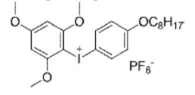
実施例1で作製した反射部材の干渉抑制層の表面に、調製したハードコート層組成物を使用し、ハードコート層を作製した。
具体的には、バーを用いて搬送速度10m/分の条件でハードコート層組成物を塗布し、60℃で150秒乾燥の後、さらに窒素パージ下酸素濃度約0.1体積%で160W/cm2の空冷メタルハライドランプ(アイグラフィックス社製)を用いて、照度400mW/cm2、照射量500mJ/cm2の紫外線を照射して塗布層を硬化させてハードコート層を形成した。
これにより、干渉抑制層の表面にハードコート層を有する以外は、実施例1と同様である、下記の層構成の反射部材を作製した。
ガラス/OCA/狭帯域コレステリック液晶層/λ/4層/干渉抑制層(TAC)/ハードコート層
ハードコート層の膜厚は、接触式の膜厚計を用いて測定した。
具体的には、まず、ハードコート層を有する実施例5の反射部材の膜厚を接触式の膜厚計を用いて測定し、また、同様に、実施例1の反射部材の膜厚を測定した。次いで、ハードコート層を有する実施例16の反射部材の膜厚から、ハードコート層の無い実施例12の投映像表示用部材の膜厚を引いて、ハードコート層の膜厚を算出した。ハードコート層の膜厚は、6.0μmであった。
干渉抑制層となるセルロースアシレートフィルム(TAC)の厚さを12μmにした以外は、実施例1と同様にして、反射部材を作製した。
[実施例7]
干渉抑制層となるセルロースアシレートフィルム(TAC)の厚さを25μmにした以外は、実施例1と同様にして、反射部材を作製した。
[実施例8]
干渉抑制層となるセルロースアシレートフィルム(TAC)の厚さを100μmにした以外は、実施例1と同様にして、反射部材を作製した。
以上の例の反射部材の層構成は、以下のとおりである。
ガラス/OCA/狭帯域コレステリック液晶層/λ/4層/干渉抑制層(TAC)
実施例1と同様にして積層体Aを作製した後、セルロースアシレートフィルム1を剥離した。
セルロースアシレートフィルム1を剥離した後の、λ/4層と3層のコレステリック液晶層との積層体に、OCAを用いて厚さ1mmのガラス板を干渉抑制層として貼着した。貼着は、λ/4層とガラス板とを対面して行った。
これ以降は、実施例1と同様にして、反射部材を作製した。作製した反射部材の層構成は、以下のとおりである。
ガラス/OCA/狭帯域コレステリック液晶層/λ/4層/OCA/ガラス
λ/4層とコレステリック反射層(選択反射層)との形成順を逆にした以外は、実施例1と同様にして、反射部材を作製した。作製した反射部材の層構成は、以下のとおりである。
ガラス/OCA/λ/4層/狭帯域コレステリック液晶層/干渉抑制層(TAC)
(コレステリック液晶層形成用組成物4、5および6)
下記の成分を混合して、入射角45°で選択反射中心波長が450nmであるコレステリック液晶層を形成するコレステリック液晶層形成用組成物4、入射角45°で選択反射中心波長が530nmであるコレステリック液晶層を形成するコレステリック液晶層形成用組成物5、および、入射角45°で選択反射中心波長が630nmであるコレステリック液晶層を形成するコレステリック液晶層形成用組成物6を調製した。
―――――――――――――――――――――――――――――――――
コレステリック液晶層形成用組成物4、5および6
―――――――――――――――――――――――――――――――――
・混合物1 100質量部
・配向制御剤1 0.05質量部
・配向制御剤3 0.02質量部
・右旋回性キラル剤LC756(BASF社製)
目標の反射波長に合わせて調整
・重合開始剤(IRGACURE OXE01、BASF社製)
1.0質量部
・溶媒(メチルエチルケトン) 溶質濃度が20質量%となる量
―――――――――――――――――――――――――――――――――
コレステリック液晶層形成用組成物4~6を用いて、上述した反射部材の作製時と同様に仮支持体上に膜厚4μmの単一層のコレステリック液晶層を作製し、可視域光の反射特性を確認した。その結果、作製したコレステリック液晶層は、全て右円偏光反射層であり、入射角45°における選択反射中心波長は、コレステリック液晶層形成用組成物4が450nm、コレステリック液晶層形成用組成物5が530nm、コレステリック液晶層形成用組成物6が630nmであった。
ガラス/OCA/コレステリック液晶層/λ/4層/干渉抑制層(TAC)
実施例1と同様に反射部材を作製した後、λ/4層および干渉抑制層を剥離して、反射部材を作製した。作製した反射部材の層構成は、以下のとおりである。
ガラス/OCA/狭帯域コレステリック液晶層
[比較例2]
実施例1と同様に反射部材を作製した後、干渉抑制層を剥離して、反射部材を作製した。作製した反射部材の層構成は、以下のとおりである。
ガラス/OCA/狭帯域コレステリック液晶層/λ/4層
配向膜を形成したセルロースアシレートフィルム1に、実施例1と同様にして、3層の狭帯域コレステリック液晶層(選択反射層)を作製した。
次いで、干渉抑制層(TAC)をガラス板に対面して、実施例1と同様にOCAによってガラス板を貼着した。作製した反射部材の層構成は、以下のとおりである。
ガラス/OCA/干渉抑制層(TAC)/狭帯域コレステリック液晶層
干渉抑制層となるセルロースアシレートフィルム(TAC)の厚さを8μmにした以外は、実施例1と同様にして、反射部材を作製した。
以上の例の反射部材の層構成は、以下のとおりである。
ガラス/OCA/狭帯域コレステリック液晶層/λ/4層/干渉抑制層(TAC)
<p偏光反射率の波長依存性>
作製した反射部材について、図10に概念的に示す装置を用いて、p偏光反射率の波長依存性を評価した。
上述したように、光ビームの波長が長いほど、波長変動による反射率の低下が生じやすい。これに対応して、光源70として、中心波長が630nm、半値幅が15nmの光ビームを照射するLEDを用いた。
光源70が出射した光ビーム(一点鎖線)は、コリメータレンズ72で平行光とし、偏光子74によってp偏光にして、直径1mmの円形の開口を有する規制板76を介して、サンプルとなる反射部材Sに入射した。反射部材Sからの反射光を、積分球78に入射して、分光器80によって、反射光の光量を測定した。
反射部材Sは、作製時におけるセルロースアシレートフィルム1(TAC)の長手方向が、p偏光の偏光方向と平行になるように配置した。すなわち、λ/4層の遅相軸は、p偏光の偏光方向に対して45°である。
また、反射部材Sは、干渉抑制層(TAC、ガラス)が光ビームの入射面とした。ただし、実施例5は、ハードコート層を、比較例1および3は、コレステリック液晶層を、比較例2はλ/4層を、それぞれ、光ビームの入射面とした。
コレステリック液晶層等の選択反射層は、法線に対する入射角度が大きくなるにしたがって、反射波長が短波長になる、いわゆるブルーシフト(短波シフト)を生じる。これを利用して、反射部材Sへの光ビームの入射角度θを変更することで、光ビームの波長変動を模した。
反射光量が最高の場合を100%として、反射率の変動を算出した。
A 反射率の変動が2%未満
B+ 反射率の変動が2%以上3%未満
B 反射率の変動が3%以上5%未満
C 反射率の変動が5%以上
A評価は、熱で光ビームの波長が変化しても、HUD画像には殆ど影響がないレベルである。
B+評価は、熱で光ビームの波長が変化した際に、HUD画像の色味が、わずかに変化するレベルである。
B評価は、熱で光ビームの波長が変化した際に、HUD画像の色味が、実用上、問題にならない程度に変化するレベルである。
C評価は、熱で光ビームの波長が変化した際に、HUD画像の色味が変化するレベルである。
反射部材の法線方向に対して45°の方向からP偏光を入射し、その正反射光(入射面内で法線方向に対して入射方向と反対側の、法線方向に対し45°の方向)を分光光度計(日本分光株式会社製、V-670)で反射率スペクトルを測定した。
反射部材Sは、作製時におけるセルロースアシレートフィルム1(TAC)の長手方向が、p偏光の偏光方向と平行になるように配置した。すなわち、λ/4層の遅相軸は、p偏光の偏光方向に対して45°である。また、反射部材Sは、干渉抑制層(TAC、ガラス)を光ビームの入射面とした。ただし、実施例5は、ハードコート層を、比較例1および3は、コレステリック液晶層を、比較例2はλ/4層を、それぞれ、光ビームの入射面とした。これらの条件は、上述した『p偏光反射率の波長依存性の評価』と同様である。
A 70%以上
B 30%以上~70%未満
C 30%未満
A評価は、光ビームの大部分を反射し、HUDのP偏光反射システムで画像が見えるレベルである。
B評価は、光ビームの一部を反射するが、HUDのP偏光反射システムで画像が見えにくいが、実用は可能なレベルである。
C評価は、光ビームがほとんど反射されず、HUDのP偏光反射システムで画像が見えないレベルである。
反射部材の干渉抑制層(TAC)面から干渉抑制層の法線方向に対し45°の方向から自然光を入射し、その透過光を分光光度計(日本分光株式会社製、V-670)測定して透過率スペクトルを測定した。ただし、実施例5は、ハードコート層を、比較例1および3は、コレステリック液晶層を、比較例2はλ/4層を、それぞれ、自然光の入射面とした。
380~780nmでの10nm毎の波長において、反射率に視感度に応じた係数およびD65光源の発光スペクトルをそれぞれ乗じて自然光の透過率を計算し、太陽光カット量として評価した。太陽光カット量の効果は、以下の評価基準にて評価した。
A 透過率60%以上
B 透過率30%以上60%未満
C 透過率30%未満
A評価は、可視光の大部分が透過して、反射部材より上流(投映光光路の上流側)の部材に太陽光がわずかに戻るレベルである。
B評価は、可視光の一部が透過して、反射部材より上流の部材に太陽光が一部戻るレベルである。
C評価は、可視光がわずかに透過して、反射部材より上流の部材に太陽光がほとんど戻るレベルである。
結果を、下記の表に示す。
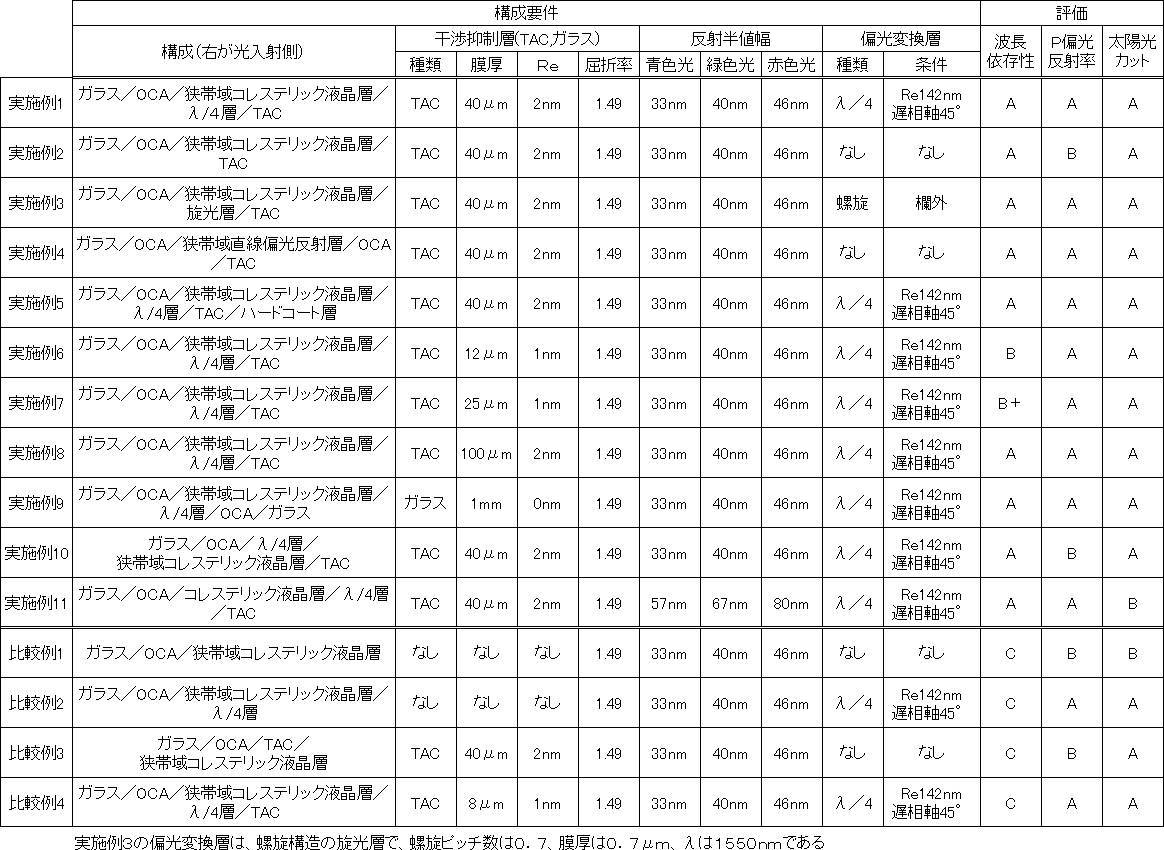
また、実施例1~5および実施例8~11に示されるように、干渉抑制層の膜厚を40μm以上とすることにより、より好適に、光ビームの波長変動に対する反射部材における反射率の低下を抑制できる。また、実施例1~実施例3および実施例10に示されるように、選択反射層であるコレステリック液晶層よりも光入射側にλ/4板および旋光層などの偏光変換層を設けることにより、p偏光反射率を向上できる。また、実施例4に示されるように、選択反射層として、直線偏光反射層も好適に利用可能である。さらに、実施例1と実施例11とに示されるように、コレステリック液晶層の反射半値幅を全て70nm以下とすることにより、高い太陽光カットの効果が得られる。
これに対して、干渉抑制層を有さない比較例1および比較例2、干渉抑制層よりもコレステリック液晶層が光ビームの入射側に位置する比較例3、ならびに、干渉抑制層の厚さが不十分である比較例4は、いずれも、光ビームの波長変動に対する反射部材における反射率の低下が大きく、HUDが投影する画像の色味の変動が生じている。
以上の結果より、本発明の効果は、明らかである。
12 画像形成部
14 中間像スクリーン
16 反射部材
18 凹面ミラー
20 ダッシュボード
24 透過窓
26 ウインドシールドガラス
30,70 光源
30R R光源
30G G光源
30B B光源
32 ミラー
32R Rミラー
32G Gミラー
32B Bミラー
34 偏光板
36 光偏向器
40 基板
42 接着層
46 選択反射層
48 偏光変換層
50 干渉抑制層
60 ハーフミラー
62 中間膜
64 ガラス板
72 コリメータレンズ
74 偏光板
76 規制板
78 積分球
80 分光器
S サンプル
Claims (10)
- 投映像を形成するための光源と、
可視光を反射する、選択反射中心波長が互いに異なる2層以上の選択反射層、および、厚さが10μm以上の干渉抑制層を有する反射部材と、を有し、
前記反射部材において、前記干渉抑制層は、前記選択反射層よりも前記光源からの光の入射側に位置する、ヘッドアップディスプレイ用プロジェクター。 - 前記選択反射層は、入射角45°で入射した可視光を反射した反射光の半値幅が70nm以下である、請求項1に記載のヘッドアップディスプレイ用プロジェクター。
- 前記光源は、出射光の半値幅が20nm以下である、請求項1または2に記載のヘッドアップディスプレイ用プロジェクター。
- 前記干渉抑制層の厚さが40μm以上である、請求項1~3のいずれか1項に記載のヘッドアップディスプレイ用プロジェクター。
- 前記選択反射層が、コレステリック液晶相を固定してなるコレステリック液晶層である、請求項1~4のいずれか1項に記載のヘッドアップディスプレイ用プロジェクター。
- 前記反射部材が、直線偏光を円偏光に変換する偏光変換層を有する、請求項1~5のいずれか1項に記載のヘッドアップディスプレイ用プロジェクター。
- 前記偏光変換層の面方向のレタデーションReが100~450nmである、請求項6に記載のヘッドアップディスプレイ用プロジェクター。
- 前記偏光変換層が、厚さ方向に沿って伸びる螺旋軸に沿って、360°未満の捩れ角で捩れ配向した液晶化合物を固定してなる層である、請求項6または7に記載のヘッドアップディスプレイ用プロジェクター。
- 前記偏光変換層が、前記干渉抑制層と前記選択反射層との間に配置される、請求項6~8のいずれか1項に記載のヘッドアップディスプレイ用プロジェクター。
- 前記選択反射層が、直線偏光反射層である、請求項1~4のいずれか1項に記載のヘッドアップディスプレイ用プロジェクター。
Priority Applications (4)
| Application Number | Priority Date | Filing Date | Title |
|---|---|---|---|
| CN202080066872.1A CN114467048A (zh) | 2019-09-27 | 2020-09-24 | 平视显示器用投影仪 |
| EP20870291.0A EP4036644A4 (en) | 2019-09-27 | 2020-09-24 | PROJECTOR FOR HEADUP DISPLAY |
| JP2021549000A JP7313457B2 (ja) | 2019-09-27 | 2020-09-24 | ヘッドアップディスプレイ用プロジェクター |
| US17/703,559 US20220221718A1 (en) | 2019-09-27 | 2022-03-24 | Head-up display projector |
Applications Claiming Priority (2)
| Application Number | Priority Date | Filing Date | Title |
|---|---|---|---|
| JP2019-177881 | 2019-09-27 | ||
| JP2019177881 | 2019-09-27 |
Related Child Applications (1)
| Application Number | Title | Priority Date | Filing Date |
|---|---|---|---|
| US17/703,559 Continuation US20220221718A1 (en) | 2019-09-27 | 2022-03-24 | Head-up display projector |
Publications (1)
| Publication Number | Publication Date |
|---|---|
| WO2021060402A1 true WO2021060402A1 (ja) | 2021-04-01 |
Family
ID=75166181
Family Applications (1)
| Application Number | Title | Priority Date | Filing Date |
|---|---|---|---|
| PCT/JP2020/036115 WO2021060402A1 (ja) | 2019-09-27 | 2020-09-24 | ヘッドアップディスプレイ用プロジェクター |
Country Status (5)
| Country | Link |
|---|---|
| US (1) | US20220221718A1 (ja) |
| EP (1) | EP4036644A4 (ja) |
| JP (1) | JP7313457B2 (ja) |
| CN (1) | CN114467048A (ja) |
| WO (1) | WO2021060402A1 (ja) |
Families Citing this family (2)
| Publication number | Priority date | Publication date | Assignee | Title |
|---|---|---|---|---|
| CN115315646A (zh) * | 2020-03-30 | 2022-11-08 | 富士胶片株式会社 | 反射膜、挡风玻璃及平视显示器系统 |
| KR20220062833A (ko) * | 2020-11-09 | 2022-05-17 | 현대자동차주식회사 | 차량용 촬영장치 |
Citations (67)
| Publication number | Priority date | Publication date | Assignee | Title |
|---|---|---|---|---|
| US2367661A (en) | 1941-12-31 | 1945-01-23 | Du Pont | Process of photopolymerization |
| US2367670A (en) | 1941-12-31 | 1945-01-23 | Du Pont | Cementing process |
| US2448828A (en) | 1946-09-04 | 1948-09-07 | Du Pont | Photopolymerization |
| US2722512A (en) | 1952-10-23 | 1955-11-01 | Du Pont | Photopolymerization process |
| US2951758A (en) | 1957-05-17 | 1960-09-06 | Du Pont | Photopolymerizable compositions and elements |
| US3046127A (en) | 1957-10-07 | 1962-07-24 | Du Pont | Photopolymerizable compositions, elements and processes |
| US3549367A (en) | 1968-05-24 | 1970-12-22 | Du Pont | Photopolymerizable compositions containing triarylimidazolyl dimers and p-aminophenyl ketones |
| JPS4841935B1 (ja) | 1969-02-20 | 1973-12-10 | ||
| US4212970A (en) | 1977-11-28 | 1980-07-15 | Fuji Photo Film Co., Ltd. | 2-Halomethyl-5-vinyl-1,3,4-oxadiazole compounds |
| US4239850A (en) | 1977-11-29 | 1980-12-16 | Fuji Photo Film Co., Ltd. | Photopolymerizable composition |
| JPS60105667A (ja) | 1983-10-12 | 1985-06-11 | ヘキスト・アクチエンゲゼルシヤフト | トリクロルメチル基を有する感光性化合物及びその製法 |
| US4683327A (en) | 1985-06-24 | 1987-07-28 | Celanese Corporation | Anisotropic heat-curable acrylic terminated monomers |
| JPS6340799B2 (ja) | 1978-07-14 | 1988-08-12 | Basf Ag | |
| JPH01272551A (ja) | 1988-04-22 | 1989-10-31 | Dainippon Printing Co Ltd | 重合性2官能アクリレートモノマー |
| JPH0529234A (ja) | 1991-07-25 | 1993-02-05 | Fujitsu Ltd | エピタキシヤル成長法 |
| JPH0529234B2 (ja) | 1984-11-27 | 1993-04-28 | Esupe Fuaburiiku Fuarumatsuoiteitsusheru Pureparaate Gmbh Unto Co Kg | |
| JPH0616616A (ja) | 1992-07-03 | 1994-01-25 | Canon Inc | 反応性液晶性化合物、高分子液晶化合物、液晶組成物および液晶素子 |
| JPH07110469A (ja) | 1993-08-16 | 1995-04-25 | Dainippon Ink & Chem Inc | 液晶表示素子及びその製造方法 |
| WO1995022586A1 (de) | 1994-02-19 | 1995-08-24 | Basf Aktiengesellschaft | Neue polymerisierbare flüssigkristalline verbindungen |
| WO1995024455A1 (de) | 1994-03-11 | 1995-09-14 | Basf Aktiengesellschaft | Neue polymerisierbare flüssigkristalline verbindungen |
| WO1997000600A2 (de) | 1995-09-01 | 1997-01-09 | Basf Aktiengesellschaft | Polymerisierbare flüssigkristalline verbindungen |
| US5622648A (en) | 1993-10-15 | 1997-04-22 | Merck Patent Gesellschaft Mit Beschrankter Haftung | Reactive liquid crystal compounds |
| JPH09506837A (ja) | 1993-12-21 | 1997-07-08 | ミネソタ・マイニング・アンド・マニュファクチュアリング・カンパニー | 多層光学フィルム |
| JPH1029997A (ja) | 1996-03-04 | 1998-02-03 | Ciba Specialty Chem Holding Inc | アルキルフェニルビスアシルホスフィンオキサイドおよび光開始剤混合物 |
| JPH1095788A (ja) | 1996-08-28 | 1998-04-14 | Ciba Specialty Chem Holding Inc | 光開始剤としての分子錯化合物 |
| WO1998023580A1 (de) | 1996-11-27 | 1998-06-04 | Basf Aktiengesellschaft | Polymerisierbare oligomesogene |
| US5770107A (en) | 1995-10-05 | 1998-06-23 | Merck Patent Gesellschaft Mit Beschrankter Haftung | Reactive liquid crystalline compound |
| WO1998052905A1 (en) | 1997-05-22 | 1998-11-26 | Rolic Ag | New polymerisable liquid crystalline compounds |
| JPH1180081A (ja) | 1997-09-05 | 1999-03-23 | Dainippon Ink & Chem Inc | 液晶性(メタ)アクリレート化合物と組成物及びこれを用いた光学異方体 |
| JP2000066385A (ja) | 1998-08-18 | 2000-03-03 | Ciba Specialty Chem Holding Inc | 高感度で高レジスト厚さのi線ホトレジスト用スルホニルオキシム類 |
| JP2000080068A (ja) | 1998-06-26 | 2000-03-21 | Ciba Specialty Chem Holding Inc | 新規o―アシルオキシム光開始剤 |
| JP2001233842A (ja) | 1999-12-15 | 2001-08-28 | Ciba Specialty Chem Holding Inc | オキシムエステルの光開始剤 |
| JP2001328973A (ja) | 2000-03-13 | 2001-11-27 | Fuji Photo Film Co Ltd | 重合性液晶化合物および光学異方性素子 |
| JP2002080478A (ja) | 2000-06-27 | 2002-03-19 | Fuji Photo Film Co Ltd | 光反応型光学活性化合物、光反応型カイラル剤、液晶組成物、液晶カラーフィルタ、光学フィルム、記録媒体、及び液晶の捻れ構造を変化させる方法 |
| JP2002080851A (ja) | 2000-06-27 | 2002-03-22 | Fuji Photo Film Co Ltd | 光反応型カイラル剤、液晶組成物、液晶カラーフィルタ、光学フィルム、記録媒体、及び液晶の捻れ構造を変化させる方法 |
| JP2002302487A (ja) | 2000-12-14 | 2002-10-18 | Fuji Photo Film Co Ltd | 光学活性化合物、光反応型キラル剤、液晶組成物、液晶の螺旋構造を変化させる方法、液晶の螺旋構造を固定化する方法、液晶カラーフィルター、光学フィルムおよび記録媒体 |
| JP2003164788A (ja) | 2001-12-03 | 2003-06-10 | Fuji Photo Film Co Ltd | 塗布装置 |
| JP2003287623A (ja) | 2002-01-23 | 2003-10-10 | Nitto Denko Corp | 光学フィルム、その製造方法、およびこれを用いた位相差フィルムならびに偏光板 |
| JP2006342166A (ja) | 2001-06-11 | 2006-12-21 | Ciba Specialty Chem Holding Inc | 組み合わされた構造を有するオキシムエステルの光開始剤 |
| JP2007523369A (ja) | 2004-02-04 | 2007-08-16 | マイクロビジョン,インク. | 走査ビームヘッドアップ表示装置および関連システム、および方法 |
| JP2007272185A (ja) | 2006-03-10 | 2007-10-18 | Fujifilm Corp | 組成物、位相差板、液晶表示装置、平均チルト角調整剤、平均チルト角の調整方法 |
| JP4223071B2 (ja) | 2006-12-27 | 2009-02-12 | 株式会社Adeka | オキシムエステル化合物及び該化合物を含有する光重合開始剤 |
| JP2010070543A (ja) | 2008-08-18 | 2010-04-02 | Asahi Glass Co Ltd | 二官能重合性化合物、液晶組成物、光学異方性材料および光学素子 |
| JP2010145745A (ja) | 2008-12-18 | 2010-07-01 | Equos Research Co Ltd | 画像形成装置、及び、ヘッドアップディスプレイ装置 |
| JP2010181852A (ja) | 2008-07-14 | 2010-08-19 | Fujifilm Corp | 光学異方性膜、光学異方性膜の製造方法、液晶セル用基板、及び液晶表示装置 |
| JP2010262028A (ja) | 2009-04-30 | 2010-11-18 | Nippon Steel Chem Co Ltd | ブラックマトリックス用感光性樹脂組成物 |
| JP4725516B2 (ja) | 2004-06-25 | 2011-07-13 | 旭硝子株式会社 | 重合性液晶化合物、液晶組成物、および光学異方性材料 |
| JP2012203237A (ja) | 2011-03-25 | 2012-10-22 | Fujifilm Corp | 光反射性フィルムの製造方法 |
| JP2012208494A (ja) | 2011-03-17 | 2012-10-25 | Fujifilm Corp | 着色感放射線性組成物、着色硬化膜、カラーフィルタ及びカラーフィルタの製造方法、固体撮像素子、液晶表示装置、並びに、染料の製造方法 |
| JP2012226303A (ja) | 2011-12-21 | 2012-11-15 | Pioneer Electronic Corp | 光源ユニット及びヘッドアップディスプレイ |
| JP2013112631A (ja) | 2011-11-28 | 2013-06-10 | Dic Corp | 重合性液晶化合物 |
| JP2013113913A (ja) | 2011-11-25 | 2013-06-10 | Fujifilm Corp | フィルムおよびその製造方法 |
| JP2013114249A (ja) | 2011-12-01 | 2013-06-10 | Toppan Printing Co Ltd | 黒色感光性樹脂組成物およびカラーフィルタ |
| JP2014500852A (ja) | 2010-10-05 | 2014-01-16 | ビーエーエスエフ ソシエタス・ヨーロピア | ベンゾカルバゾール化合物のオキシムエステル誘導体ならびに前記誘導体の光重合性の組成物における光開始剤としての使用 |
| JP2014034581A (ja) | 2012-08-07 | 2014-02-24 | Fujifilm Corp | 液晶組成物、高分子、フィルムおよびコレステリック液晶 |
| WO2014112575A1 (ja) | 2013-01-18 | 2014-07-24 | 富士フイルム株式会社 | 光学フィルム、偏光板、及び画像表示装置 |
| JP2014137466A (ja) | 2013-01-16 | 2014-07-28 | Jsr Corp | 感放射線性着色組成物、着色硬化膜及び表示素子 |
| WO2015115390A1 (ja) | 2014-01-28 | 2015-08-06 | 富士フイルム株式会社 | 重合性化合物、重合性組成物、フィルム、および投映像表示用ハーフミラー |
| WO2015141759A1 (ja) * | 2014-03-20 | 2015-09-24 | 富士フイルム株式会社 | 反射部材、投映スクリーン、コンバイナ、および、遮熱部材 |
| WO2015147243A1 (ja) | 2014-03-28 | 2015-10-01 | 富士フイルム株式会社 | 重合性化合物、ポリマー、重合性組成物、フィルム、および投映像表示用ハーフミラー |
| WO2016003090A1 (ko) | 2014-06-30 | 2016-01-07 | 최창준 | H-bridge 회로를 이용한 직류 전력선 통신 제어장치 |
| WO2016035873A1 (ja) | 2014-09-05 | 2016-03-10 | 富士フイルム株式会社 | 重合性化合物、ポリマー、重合性組成物、およびフィルム |
| WO2016047648A1 (ja) | 2014-09-25 | 2016-03-31 | 富士フイルム株式会社 | 重合性化合物を含む重合性組成物、フィルム、および投映像表示用ハーフミラー |
| JP2016053149A (ja) | 2014-03-28 | 2016-04-14 | 富士フイルム株式会社 | 重合性化合物、ポリマー、重合性組成物、フィルム、および投映像表示用ハーフミラー |
| WO2019035358A1 (ja) * | 2017-08-15 | 2019-02-21 | 富士フイルム株式会社 | 車両用ミラー、車両用画像表示機能付きミラー |
| JP2019132902A (ja) * | 2018-01-29 | 2019-08-08 | 大日本印刷株式会社 | 表示装置、移動体、照明装置および反射板 |
| WO2019163969A1 (ja) * | 2018-02-23 | 2019-08-29 | 富士フイルム株式会社 | 画像表示用合わせガラスの製造方法、画像表示用合わせガラス、および、画像表示システム |
Family Cites Families (3)
| Publication number | Priority date | Publication date | Assignee | Title |
|---|---|---|---|---|
| JP6321988B2 (ja) * | 2014-02-20 | 2018-05-09 | 富士フイルム株式会社 | 遮熱用途に使用可能な反射部材および反射部材を含むプロジェクター |
| CN106255917B (zh) * | 2014-04-30 | 2018-12-07 | 夏普株式会社 | 反射投影型显示装置 |
| EP3321719B1 (en) * | 2015-07-08 | 2021-12-01 | FUJIFILM Corporation | Mirror equipped with image display function |
-
2020
- 2020-09-24 WO PCT/JP2020/036115 patent/WO2021060402A1/ja active Application Filing
- 2020-09-24 JP JP2021549000A patent/JP7313457B2/ja active Active
- 2020-09-24 EP EP20870291.0A patent/EP4036644A4/en active Pending
- 2020-09-24 CN CN202080066872.1A patent/CN114467048A/zh active Pending
-
2022
- 2022-03-24 US US17/703,559 patent/US20220221718A1/en active Pending
Patent Citations (69)
| Publication number | Priority date | Publication date | Assignee | Title |
|---|---|---|---|---|
| US2367661A (en) | 1941-12-31 | 1945-01-23 | Du Pont | Process of photopolymerization |
| US2367670A (en) | 1941-12-31 | 1945-01-23 | Du Pont | Cementing process |
| US2448828A (en) | 1946-09-04 | 1948-09-07 | Du Pont | Photopolymerization |
| US2722512A (en) | 1952-10-23 | 1955-11-01 | Du Pont | Photopolymerization process |
| US2951758A (en) | 1957-05-17 | 1960-09-06 | Du Pont | Photopolymerizable compositions and elements |
| US3046127A (en) | 1957-10-07 | 1962-07-24 | Du Pont | Photopolymerizable compositions, elements and processes |
| US3549367A (en) | 1968-05-24 | 1970-12-22 | Du Pont | Photopolymerizable compositions containing triarylimidazolyl dimers and p-aminophenyl ketones |
| JPS4841935B1 (ja) | 1969-02-20 | 1973-12-10 | ||
| US4212970A (en) | 1977-11-28 | 1980-07-15 | Fuji Photo Film Co., Ltd. | 2-Halomethyl-5-vinyl-1,3,4-oxadiazole compounds |
| US4239850A (en) | 1977-11-29 | 1980-12-16 | Fuji Photo Film Co., Ltd. | Photopolymerizable composition |
| JPS6340799B2 (ja) | 1978-07-14 | 1988-08-12 | Basf Ag | |
| JPS60105667A (ja) | 1983-10-12 | 1985-06-11 | ヘキスト・アクチエンゲゼルシヤフト | トリクロルメチル基を有する感光性化合物及びその製法 |
| JPH0529234B2 (ja) | 1984-11-27 | 1993-04-28 | Esupe Fuaburiiku Fuarumatsuoiteitsusheru Pureparaate Gmbh Unto Co Kg | |
| US4683327A (en) | 1985-06-24 | 1987-07-28 | Celanese Corporation | Anisotropic heat-curable acrylic terminated monomers |
| JPH01272551A (ja) | 1988-04-22 | 1989-10-31 | Dainippon Printing Co Ltd | 重合性2官能アクリレートモノマー |
| JPH0529234A (ja) | 1991-07-25 | 1993-02-05 | Fujitsu Ltd | エピタキシヤル成長法 |
| JPH0616616A (ja) | 1992-07-03 | 1994-01-25 | Canon Inc | 反応性液晶性化合物、高分子液晶化合物、液晶組成物および液晶素子 |
| JPH07110469A (ja) | 1993-08-16 | 1995-04-25 | Dainippon Ink & Chem Inc | 液晶表示素子及びその製造方法 |
| US5622648A (en) | 1993-10-15 | 1997-04-22 | Merck Patent Gesellschaft Mit Beschrankter Haftung | Reactive liquid crystal compounds |
| JPH09506837A (ja) | 1993-12-21 | 1997-07-08 | ミネソタ・マイニング・アンド・マニュファクチュアリング・カンパニー | 多層光学フィルム |
| WO1995022586A1 (de) | 1994-02-19 | 1995-08-24 | Basf Aktiengesellschaft | Neue polymerisierbare flüssigkristalline verbindungen |
| WO1995024455A1 (de) | 1994-03-11 | 1995-09-14 | Basf Aktiengesellschaft | Neue polymerisierbare flüssigkristalline verbindungen |
| WO1997000600A2 (de) | 1995-09-01 | 1997-01-09 | Basf Aktiengesellschaft | Polymerisierbare flüssigkristalline verbindungen |
| US5770107A (en) | 1995-10-05 | 1998-06-23 | Merck Patent Gesellschaft Mit Beschrankter Haftung | Reactive liquid crystalline compound |
| JPH1029997A (ja) | 1996-03-04 | 1998-02-03 | Ciba Specialty Chem Holding Inc | アルキルフェニルビスアシルホスフィンオキサイドおよび光開始剤混合物 |
| JPH1095788A (ja) | 1996-08-28 | 1998-04-14 | Ciba Specialty Chem Holding Inc | 光開始剤としての分子錯化合物 |
| WO1998023580A1 (de) | 1996-11-27 | 1998-06-04 | Basf Aktiengesellschaft | Polymerisierbare oligomesogene |
| WO1998052905A1 (en) | 1997-05-22 | 1998-11-26 | Rolic Ag | New polymerisable liquid crystalline compounds |
| JPH1180081A (ja) | 1997-09-05 | 1999-03-23 | Dainippon Ink & Chem Inc | 液晶性(メタ)アクリレート化合物と組成物及びこれを用いた光学異方体 |
| JP2000080068A (ja) | 1998-06-26 | 2000-03-21 | Ciba Specialty Chem Holding Inc | 新規o―アシルオキシム光開始剤 |
| JP4454067B2 (ja) | 1998-06-26 | 2010-04-21 | チバ ホールディング インコーポレーテッド | 新規o−アシルオキシム光開始剤 |
| JP2000066385A (ja) | 1998-08-18 | 2000-03-03 | Ciba Specialty Chem Holding Inc | 高感度で高レジスト厚さのi線ホトレジスト用スルホニルオキシム類 |
| JP2001233842A (ja) | 1999-12-15 | 2001-08-28 | Ciba Specialty Chem Holding Inc | オキシムエステルの光開始剤 |
| JP2001328973A (ja) | 2000-03-13 | 2001-11-27 | Fuji Photo Film Co Ltd | 重合性液晶化合物および光学異方性素子 |
| JP2002080851A (ja) | 2000-06-27 | 2002-03-22 | Fuji Photo Film Co Ltd | 光反応型カイラル剤、液晶組成物、液晶カラーフィルタ、光学フィルム、記録媒体、及び液晶の捻れ構造を変化させる方法 |
| JP2002080478A (ja) | 2000-06-27 | 2002-03-19 | Fuji Photo Film Co Ltd | 光反応型光学活性化合物、光反応型カイラル剤、液晶組成物、液晶カラーフィルタ、光学フィルム、記録媒体、及び液晶の捻れ構造を変化させる方法 |
| JP2002302487A (ja) | 2000-12-14 | 2002-10-18 | Fuji Photo Film Co Ltd | 光学活性化合物、光反応型キラル剤、液晶組成物、液晶の螺旋構造を変化させる方法、液晶の螺旋構造を固定化する方法、液晶カラーフィルター、光学フィルムおよび記録媒体 |
| JP2006342166A (ja) | 2001-06-11 | 2006-12-21 | Ciba Specialty Chem Holding Inc | 組み合わされた構造を有するオキシムエステルの光開始剤 |
| JP2003164788A (ja) | 2001-12-03 | 2003-06-10 | Fuji Photo Film Co Ltd | 塗布装置 |
| JP2003287623A (ja) | 2002-01-23 | 2003-10-10 | Nitto Denko Corp | 光学フィルム、その製造方法、およびこれを用いた位相差フィルムならびに偏光板 |
| JP2007523369A (ja) | 2004-02-04 | 2007-08-16 | マイクロビジョン,インク. | 走査ビームヘッドアップ表示装置および関連システム、および方法 |
| JP4725516B2 (ja) | 2004-06-25 | 2011-07-13 | 旭硝子株式会社 | 重合性液晶化合物、液晶組成物、および光学異方性材料 |
| JP2007272185A (ja) | 2006-03-10 | 2007-10-18 | Fujifilm Corp | 組成物、位相差板、液晶表示装置、平均チルト角調整剤、平均チルト角の調整方法 |
| JP4223071B2 (ja) | 2006-12-27 | 2009-02-12 | 株式会社Adeka | オキシムエステル化合物及び該化合物を含有する光重合開始剤 |
| JP2010181852A (ja) | 2008-07-14 | 2010-08-19 | Fujifilm Corp | 光学異方性膜、光学異方性膜の製造方法、液晶セル用基板、及び液晶表示装置 |
| JP2010070543A (ja) | 2008-08-18 | 2010-04-02 | Asahi Glass Co Ltd | 二官能重合性化合物、液晶組成物、光学異方性材料および光学素子 |
| JP2010145745A (ja) | 2008-12-18 | 2010-07-01 | Equos Research Co Ltd | 画像形成装置、及び、ヘッドアップディスプレイ装置 |
| JP2010262028A (ja) | 2009-04-30 | 2010-11-18 | Nippon Steel Chem Co Ltd | ブラックマトリックス用感光性樹脂組成物 |
| JP2014500852A (ja) | 2010-10-05 | 2014-01-16 | ビーエーエスエフ ソシエタス・ヨーロピア | ベンゾカルバゾール化合物のオキシムエステル誘導体ならびに前記誘導体の光重合性の組成物における光開始剤としての使用 |
| JP2012208494A (ja) | 2011-03-17 | 2012-10-25 | Fujifilm Corp | 着色感放射線性組成物、着色硬化膜、カラーフィルタ及びカラーフィルタの製造方法、固体撮像素子、液晶表示装置、並びに、染料の製造方法 |
| JP2012203237A (ja) | 2011-03-25 | 2012-10-22 | Fujifilm Corp | 光反射性フィルムの製造方法 |
| JP2013113913A (ja) | 2011-11-25 | 2013-06-10 | Fujifilm Corp | フィルムおよびその製造方法 |
| JP2013112631A (ja) | 2011-11-28 | 2013-06-10 | Dic Corp | 重合性液晶化合物 |
| JP2013114249A (ja) | 2011-12-01 | 2013-06-10 | Toppan Printing Co Ltd | 黒色感光性樹脂組成物およびカラーフィルタ |
| JP2012226303A (ja) | 2011-12-21 | 2012-11-15 | Pioneer Electronic Corp | 光源ユニット及びヘッドアップディスプレイ |
| JP2014034581A (ja) | 2012-08-07 | 2014-02-24 | Fujifilm Corp | 液晶組成物、高分子、フィルムおよびコレステリック液晶 |
| JP2014137466A (ja) | 2013-01-16 | 2014-07-28 | Jsr Corp | 感放射線性着色組成物、着色硬化膜及び表示素子 |
| WO2014112575A1 (ja) | 2013-01-18 | 2014-07-24 | 富士フイルム株式会社 | 光学フィルム、偏光板、及び画像表示装置 |
| WO2015115390A1 (ja) | 2014-01-28 | 2015-08-06 | 富士フイルム株式会社 | 重合性化合物、重合性組成物、フィルム、および投映像表示用ハーフミラー |
| JP2015163596A (ja) | 2014-01-28 | 2015-09-10 | 富士フイルム株式会社 | 重合性化合物、ポリマー、重合性組成物、フィルム、および投映像表示用ハーフミラー |
| WO2015141759A1 (ja) * | 2014-03-20 | 2015-09-24 | 富士フイルム株式会社 | 反射部材、投映スクリーン、コンバイナ、および、遮熱部材 |
| WO2015147243A1 (ja) | 2014-03-28 | 2015-10-01 | 富士フイルム株式会社 | 重合性化合物、ポリマー、重合性組成物、フィルム、および投映像表示用ハーフミラー |
| JP2016053149A (ja) | 2014-03-28 | 2016-04-14 | 富士フイルム株式会社 | 重合性化合物、ポリマー、重合性組成物、フィルム、および投映像表示用ハーフミラー |
| WO2016003090A1 (ko) | 2014-06-30 | 2016-01-07 | 최창준 | H-bridge 회로를 이용한 직류 전력선 통신 제어장치 |
| WO2016035873A1 (ja) | 2014-09-05 | 2016-03-10 | 富士フイルム株式会社 | 重合性化合物、ポリマー、重合性組成物、およびフィルム |
| WO2016047648A1 (ja) | 2014-09-25 | 2016-03-31 | 富士フイルム株式会社 | 重合性化合物を含む重合性組成物、フィルム、および投映像表示用ハーフミラー |
| WO2019035358A1 (ja) * | 2017-08-15 | 2019-02-21 | 富士フイルム株式会社 | 車両用ミラー、車両用画像表示機能付きミラー |
| JP2019132902A (ja) * | 2018-01-29 | 2019-08-08 | 大日本印刷株式会社 | 表示装置、移動体、照明装置および反射板 |
| WO2019163969A1 (ja) * | 2018-02-23 | 2019-08-29 | 富士フイルム株式会社 | 画像表示用合わせガラスの製造方法、画像表示用合わせガラス、および、画像表示システム |
Non-Patent Citations (3)
| Title |
|---|
| ADVANCED MATERIALS, vol. 5, 1993, pages 107 |
| MAKROMOL. CHEM., vol. 190, 1989, pages 2255 |
| See also references of EP4036644A4 |
Also Published As
| Publication number | Publication date |
|---|---|
| JP7313457B2 (ja) | 2023-07-24 |
| JPWO2021060402A1 (ja) | 2021-04-01 |
| CN114467048A (zh) | 2022-05-10 |
| EP4036644A1 (en) | 2022-08-03 |
| EP4036644A4 (en) | 2022-11-30 |
| US20220221718A1 (en) | 2022-07-14 |
Similar Documents
| Publication | Publication Date | Title |
|---|---|---|
| JP6580143B2 (ja) | 投映システムおよび投映システムの中間像スクリーンの製造方法 | |
| JP6336572B2 (ja) | 反射部材、投映スクリーン、コンバイナ、および、遮熱部材 | |
| JP7177176B2 (ja) | 投映像表示用部材、ウインドシールドガラスおよびヘッドアップディスプレイシステム | |
| JP6530763B2 (ja) | 画像表示機能付きミラー | |
| JP7382392B2 (ja) | 投映像表示用部材、ウインドシールドガラスおよびヘッドアップディスプレイシステム | |
| JP6768567B2 (ja) | ウインドシールドガラス、ヘッドアップディスプレイシステム、およびハーフミラーフィルム | |
| JP7299920B2 (ja) | 投映像表示用部材、ウインドシールドガラスおよびヘッドアップディスプレイシステム | |
| WO2018084076A1 (ja) | ウインドシールドガラス、ヘッドアップディスプレイシステム、およびハーフミラーフィルム | |
| JP6880244B2 (ja) | 投映像表示用部材、ウインドシールドガラスおよびヘッドアップディスプレイシステム | |
| JP6194256B2 (ja) | 投映システムおよびプロジェクター | |
| WO2017212755A1 (ja) | ヘッドアップディスプレイシステム | |
| WO2020179787A1 (ja) | 投映像表示用積層フィルム、投映像表示用の合わせガラス、および、画像表示システム | |
| US20220221718A1 (en) | Head-up display projector | |
| JP6193471B2 (ja) | 投映像表示用部材および投映像表示用部材を含む投映システム | |
| CN111566068B (zh) | 图像显示用夹层玻璃的制造方法、图像显示用夹层玻璃及图像显示系统 | |
| JP7260449B2 (ja) | 投映像表示用部材、ウインドシールドガラスおよびヘッドアップディスプレイシステム | |
| JP2019012211A (ja) | 投映像表示用ハーフミラー、ウインドシールドガラスおよびヘッドアップディスプレイシステム | |
| WO2021060407A1 (ja) | 投映像表示用部材、ウインドシールドガラスおよびヘッドアップディスプレイシステム | |
| WO2022123946A1 (ja) | 反射フィルム、ウインドシールドガラスおよびヘッドアップディスプレイシステム | |
| WO2021200655A1 (ja) | 反射フィルム、ウインドシールドガラスおよびヘッドアップディスプレイシステム | |
| JP7247068B2 (ja) | プロジェクター用反射部材およびヘッドアップディスプレイ用プロジェクター | |
| JP2019038707A (ja) | 合わせガラスの製造方法 |
Legal Events
| Date | Code | Title | Description |
|---|---|---|---|
| 121 | Ep: the epo has been informed by wipo that ep was designated in this application |
Ref document number: 20870291 Country of ref document: EP Kind code of ref document: A1 |
|
| ENP | Entry into the national phase |
Ref document number: 2021549000 Country of ref document: JP Kind code of ref document: A |
|
| NENP | Non-entry into the national phase |
Ref country code: DE |
|
| WWE | Wipo information: entry into national phase |
Ref document number: 2020870291 Country of ref document: EP |
|
| ENP | Entry into the national phase |
Ref document number: 2020870291 Country of ref document: EP Effective date: 20220428 |