WO2021002170A1 - 配線システム及び変更された配線システムの製造方法 - Google Patents
配線システム及び変更された配線システムの製造方法 Download PDFInfo
- Publication number
- WO2021002170A1 WO2021002170A1 PCT/JP2020/022969 JP2020022969W WO2021002170A1 WO 2021002170 A1 WO2021002170 A1 WO 2021002170A1 JP 2020022969 W JP2020022969 W JP 2020022969W WO 2021002170 A1 WO2021002170 A1 WO 2021002170A1
- Authority
- WO
- WIPO (PCT)
- Prior art keywords
- wiring
- wiring member
- members
- protective
- control unit
- Prior art date
- Legal status (The legal status is an assumption and is not a legal conclusion. Google has not performed a legal analysis and makes no representation as to the accuracy of the status listed.)
- Ceased
Links
Images


Classifications
-
- H—ELECTRICITY
- H02—GENERATION; CONVERSION OR DISTRIBUTION OF ELECTRIC POWER
- H02G—INSTALLATION OF ELECTRIC CABLES OR LINES, OR OF COMBINED OPTICAL AND ELECTRIC CABLES OR LINES
- H02G3/00—Installations of electric cables or lines or protective tubing therefor in or on buildings, equivalent structures or vehicles
- H02G3/02—Details
- H02G3/04—Protective tubing or conduits, e.g. cable ladders or cable troughs
- H02G3/0462—Tubings, i.e. having a closed section
- H02G3/0487—Tubings, i.e. having a closed section with a non-circular cross-section
-
- B—PERFORMING OPERATIONS; TRANSPORTING
- B60—VEHICLES IN GENERAL
- B60R—VEHICLES, VEHICLE FITTINGS, OR VEHICLE PARTS, NOT OTHERWISE PROVIDED FOR
- B60R16/00—Electric or fluid circuits specially adapted for vehicles and not otherwise provided for; Arrangement of elements of electric or fluid circuits specially adapted for vehicles and not otherwise provided for
- B60R16/02—Electric or fluid circuits specially adapted for vehicles and not otherwise provided for; Arrangement of elements of electric or fluid circuits specially adapted for vehicles and not otherwise provided for electric constitutive elements
- B60R16/0207—Wire harnesses
- B60R16/0215—Protecting, fastening and routing means therefor
-
- B—PERFORMING OPERATIONS; TRANSPORTING
- B60—VEHICLES IN GENERAL
- B60R—VEHICLES, VEHICLE FITTINGS, OR VEHICLE PARTS, NOT OTHERWISE PROVIDED FOR
- B60R16/00—Electric or fluid circuits specially adapted for vehicles and not otherwise provided for; Arrangement of elements of electric or fluid circuits specially adapted for vehicles and not otherwise provided for
- B60R16/02—Electric or fluid circuits specially adapted for vehicles and not otherwise provided for; Arrangement of elements of electric or fluid circuits specially adapted for vehicles and not otherwise provided for electric constitutive elements
- B60R16/03—Electric or fluid circuits specially adapted for vehicles and not otherwise provided for; Arrangement of elements of electric or fluid circuits specially adapted for vehicles and not otherwise provided for electric constitutive elements for supply of electrical power to vehicle subsystems or for
-
- F—MECHANICAL ENGINEERING; LIGHTING; HEATING; WEAPONS; BLASTING
- F16—ENGINEERING ELEMENTS AND UNITS; GENERAL MEASURES FOR PRODUCING AND MAINTAINING EFFECTIVE FUNCTIONING OF MACHINES OR INSTALLATIONS; THERMAL INSULATION IN GENERAL
- F16L—PIPES; JOINTS OR FITTINGS FOR PIPES; SUPPORTS FOR PIPES, CABLES OR PROTECTIVE TUBING; MEANS FOR THERMAL INSULATION IN GENERAL
- F16L57/00—Protection of pipes or objects of similar shape against external or internal damage or wear
-
- H—ELECTRICITY
- H01—ELECTRIC ELEMENTS
- H01B—CABLES; CONDUCTORS; INSULATORS; SELECTION OF MATERIALS FOR THEIR CONDUCTIVE, INSULATING OR DIELECTRIC PROPERTIES
- H01B13/00—Apparatus or processes specially adapted for manufacturing conductors or cables
- H01B13/012—Apparatus or processes specially adapted for manufacturing conductors or cables for manufacturing wire harnesses
-
- H—ELECTRICITY
- H01—ELECTRIC ELEMENTS
- H01B—CABLES; CONDUCTORS; INSULATORS; SELECTION OF MATERIALS FOR THEIR CONDUCTIVE, INSULATING OR DIELECTRIC PROPERTIES
- H01B7/00—Insulated conductors or cables characterised by their form
-
- H—ELECTRICITY
- H02—GENERATION; CONVERSION OR DISTRIBUTION OF ELECTRIC POWER
- H02G—INSTALLATION OF ELECTRIC CABLES OR LINES, OR OF COMBINED OPTICAL AND ELECTRIC CABLES OR LINES
- H02G1/00—Methods or apparatus specially adapted for installing, maintaining, repairing or dismantling electric cables or lines
-
- H—ELECTRICITY
- H02—GENERATION; CONVERSION OR DISTRIBUTION OF ELECTRIC POWER
- H02G—INSTALLATION OF ELECTRIC CABLES OR LINES, OR OF COMBINED OPTICAL AND ELECTRIC CABLES OR LINES
- H02G3/00—Installations of electric cables or lines or protective tubing therefor in or on buildings, equivalent structures or vehicles
- H02G3/02—Details
- H02G3/04—Protective tubing or conduits, e.g. cable ladders or cable troughs
- H02G3/0406—Details thereof
-
- H—ELECTRICITY
- H02—GENERATION; CONVERSION OR DISTRIBUTION OF ELECTRIC POWER
- H02G—INSTALLATION OF ELECTRIC CABLES OR LINES, OR OF COMBINED OPTICAL AND ELECTRIC CABLES OR LINES
- H02G3/00—Installations of electric cables or lines or protective tubing therefor in or on buildings, equivalent structures or vehicles
- H02G3/02—Details
- H02G3/04—Protective tubing or conduits, e.g. cable ladders or cable troughs
- H02G3/0462—Tubings, i.e. having a closed section
- H02G3/0481—Tubings, i.e. having a closed section with a circular cross-section
-
- H—ELECTRICITY
- H02—GENERATION; CONVERSION OR DISTRIBUTION OF ELECTRIC POWER
- H02G—INSTALLATION OF ELECTRIC CABLES OR LINES, OR OF COMBINED OPTICAL AND ELECTRIC CABLES OR LINES
- H02G3/00—Installations of electric cables or lines or protective tubing therefor in or on buildings, equivalent structures or vehicles
- H02G3/02—Details
- H02G3/08—Distribution boxes; Connection or junction boxes
- H02G3/16—Distribution boxes; Connection or junction boxes structurally associated with support for line-connecting terminals within the box
-
- H—ELECTRICITY
- H02—GENERATION; CONVERSION OR DISTRIBUTION OF ELECTRIC POWER
- H02G—INSTALLATION OF ELECTRIC CABLES OR LINES, OR OF COMBINED OPTICAL AND ELECTRIC CABLES OR LINES
- H02G3/00—Installations of electric cables or lines or protective tubing therefor in or on buildings, equivalent structures or vehicles
- H02G3/30—Installations of cables or lines on walls, floors or ceilings
Definitions
- This disclosure relates to a wiring system and a modified wiring system manufacturing method.
- Patent Document 1 discloses that electric wires and signal lines are branched in an intermediate branch box and connected to each load. Further, the intermediate branch box may be provided with a control unit, and the connector provided at the end of the wire harness drawn from each load may be connected to the connector provided in the intermediate branch box. It is disclosed.
- the control unit when connecting the control unit to a plurality of loads, it is desired to facilitate the wiring work of the wire harness. Also, the load built into the vehicle may be replaced or removed. In such a case, it is desired that the wire harness can be easily replaced or deleted.
- an object of the present disclosure is to make it easy to dispose a plurality of wiring members in a vehicle, and to easily cope with partial replacement or deletion of the plurality of wiring members.
- the wiring system of the present disclosure includes a control unit, a plurality of devices connected to the control unit, a plurality of wiring members forming at least a part of a wiring path connecting the control unit and the plurality of devices, and a plurality of wiring members.
- the plurality of protective portions are a wiring system in which the plurality of wiring members are divided into a plurality of groups and protected, and the plurality of protective portions are connected in a separable manner. ..
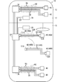
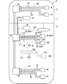
- FIG. 1 is an explanatory diagram showing a state in which a wiring system is incorporated in an automobile.
- FIG. 2 is a perspective view showing a protective portion.
- FIG. 3 is a plan view showing the protection unit.
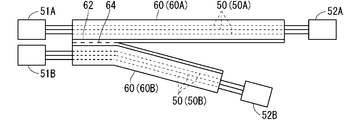
- FIG. 4 is a plan view showing an example in which the protective portion is branched in the middle.
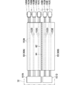
- FIG. 5 is a plan view showing another example in which the protection unit protects the wiring member.
- FIG. 6 is an explanatory diagram showing how the protective portion is removed.
- FIG. 7 is an explanatory diagram showing how another protective unit is added.
- the wiring system of this disclosure is as follows.
- a control unit a plurality of devices connected to the control unit, a plurality of wiring members forming at least a part of a wiring path connecting the control unit and the plurality of devices, and a plurality of protective units.
- the plurality of protection units is a wiring system in which the plurality of wiring members are divided into a plurality of groups to protect the plurality of protection units, and the plurality of protection units are connected in a separable manner. Since the plurality of protective portions are connected in a separable manner, it is easy to collectively dispose the plurality of wiring members in the vehicle. Further, by separating the plurality of protective portions, it is possible to easily deal with partial replacement or deletion of the plurality of wiring members.
- the plurality of wiring members include a common wiring member that is commonly wired in a vehicle and a selective wiring member that is selectively wired in a vehicle, and the common wiring member and the selective wiring member are separate. It may be protected by the protection part of.
- the common wiring member may include at least one of a wiring member for an airbag and a wiring member for a brake. It is easy to leave at least one of the wiring member for the airbag and the wiring member for the brake as a common wiring member in a state of being incorporated in the vehicle.
- the selected wiring member may include at least one of a wiring member for a headlamp, a wiring member for an air conditioner, a wiring member for indoor lighting, and a wiring member for a speaker. At least one of a wiring member for a headlamp, a wiring member for an air conditioner, a wiring member for interior lighting, and a wiring member for a speaker is easily removed from the vehicle as a selection wiring member.
- the plurality of protective portions may be connected via a connecting portion, and a breaking line that is easily broken may be formed in the connecting portion. Multiple protections are easily separated by the break line.
- the ends of the plurality of wiring members may be connected to the connector in a state of being separated from at least the plurality of protective portions.
- a plurality of wiring members are disconnected from the connector or connected to the connector to the device to be connected to each protection unit.
- the manufacturing method of the modified wiring system of this disclosure is as follows.
- a plurality of wiring members and a plurality of protective portions are provided, and the plurality of wiring members are protected by the plurality of protective portions in a state of being divided into a plurality of groups, and the plurality of protective portions can be separated.
- the step (a) in which the wiring system connected in the embodiment is arranged in the vehicle and the step (a) a part and the rest of the plurality of protective portions are separated, and the partial protective portion is separated.
- the wiring member protected by the partial protection portion are left in the vehicle, and the remaining protection portion and the wiring member protected by the remaining protection portion are removed from the vehicle.
- a modified wiring system manufacturing method comprising the step (b) to be performed.
- the plurality of protective portions are connected in a separable manner, it is easy to collectively dispose the plurality of wiring members in the vehicle. Further, by separating the plurality of protective portions, it is possible to easily deal with partial replacement or deletion of the plurality of wiring members.
- the present inventor examined changes in the wire harness architecture when consumers found a desire to "do things in the car". As a result, unknown equipment may appear in order to deal with "what to do in the car” after the car is manufactured, and even in such a case, a wire harness architecture that can be mounted on the car without problems is required. It was found that it can be done.
- the conventional wire harness architecture is formed by a wire harness that binds a plurality of system circuits into one.
- the system circuit is intended to be a circuit related to equipment specifications.
- the conventional wire harness architecture if you want to add a new system circuit, you can only do it by replacing the entire wire harness. This is because, in the conventional wire harness architecture, the electric wires of a plurality of system circuits constituting the wire harness are tied together with tape or the like. Therefore, in the conventional wire harness architecture, the system circuit cannot be easily replaced when unknown equipment appears.
- the inventor of the present application predicts that, in predicting the future of automobiles, consumers will find a desire to "do in the car", and as a result, unknown equipment that has never existed in the automobile market will emerge. did.
- the wire harness architecture according to the present disclosure has a remarkable effect in that the system circuit can be easily replaced even when unknown equipment appears.
- FIG. 1 is an explanatory diagram showing a state in which the wiring system 20 is incorporated in the automobile 10.
- the automobile 10 includes a vehicle 12 including a body that forms the outer shape of the automobile.
- the space inside the vehicle 12 is divided into a vehicle compartment 16 and a front chamber 17 by a partition panel 14.
- the passenger compartment 16 is a space for accommodating occupants.
- the passenger compartment 16 may include a space for accommodating luggage.
- the front chamber 17 is a space on the front side of the passenger compartment 16.
- the front chamber 17 is an engine chamber.
- the front chamber 17 may be a motor chamber.
- the front chamber 17 may be an engine and a motor chamber.
- the front chamber 17 is a luggage compartment.
- At least one control unit 30, 32, 34, 36 is mounted on the automobile 10.
- the control units 30, 32, 34, and 36 are composed of a computer including a CPU (Central Processing Unit).
- CPU Central Processing Unit
- the central control unit 30 is sometimes referred to as a central ECU (Electronic Control Unit).
- the area control units 32, 34, and 36 may also be referred to as an area ECU or a zone ECU.
- the area control units 32, 34, and 36 are arranged in each of the plurality of areas when the automobile 10 is considered to be spatially divided into a plurality of areas.
- the automobile 10 is divided into an area in the front chamber 17 and two front and rear areas in the passenger compartment 16.
- the method of dividing the above area is an example, and may be divided into more or less. Further, the area may be set separately on the left and right in the automobile, or the area may be set separately on the floor, roof, or the like.
- a plurality of devices 40 are provided in each of the plurality of areas.
- the area control units 32, 34, and 36 are connected to the equipment 40 arranged in their own area via a signal line.
- the area control units 32, 34, and 36 transmit or receive at least one of the signals to and from the devices belonging to their own area.
- the central control unit 30 is connected to the above area control units 32, 34, 36 via a signal line 31. As a result, the central control unit 30 performs integrated control of the area control units 32, 34, and 36.
- the central control unit 30 may be omitted. Further, the area control units 32, 34, and 36 may be omitted. In this case, a branch unit for branching the signal line from the central control unit 30 may be provided at the location where the area control units 32, 34, and 36 are provided.
- the automobile 10 is provided with a power source 70.
- the power supply 70 and the plurality of area control units 32, 34, 36 are directly or indirectly connected via the power supply line 72.
- the power supply 70 supplies power to the area control units 32, 34, and 36.
- the ground ground portion 74 in the vehicle is directly or indirectly connected to the plurality of area control units 32, 34, 36 via the ground wire 76.
- the power supply circuit and the ground circuit may be configured as wiring of a system different from the above signal circuit.
- the electric wire 70 and the ground ground portion 74 may be connected to the central control unit 30 via the power supply line 72, the ground wire 76, and the like.
- a plurality of connectors are provided for each of the area control units 32, 34, and 36.
- the wiring system 20 includes an area control unit 32 as an example of a control unit, a plurality of devices 40, a plurality of wiring members 50, and a plurality of protection units 60.
- the example of the wiring system 20 described below may be similarly applied to other area control units 34 and 36.
- the plurality of devices 40 are connected to the area control unit 32.
- the device 40A and the device 40B are shown.
- the plurality of devices 40 when a plurality of devices 40 are distinguished, they are distinguished as device 40A and device 40B.
- the plurality of devices 40 may be more numerous.
- the plurality of wiring members 50 are portions that form at least a part of a wiring path that connects the area control unit 32 and the plurality of devices 40A and 40B.
- the plurality of wiring members 50 include a wiring member 50A and a wiring member 50B.
- a plurality of wiring members 50 are distinguished, they are distinguished as wiring members 50A and 50B.
- the wiring member 50A is a wiring member that connects the area control unit 32 and the device 40A. More specifically, the wiring member 50A is an electric wire.
- the wiring member 50A includes an electric wire for signal transmission, an electric wire for electric power transmission, and an electric wire for grounding.
- the signal wire may be one, two or more.
- the wiring member 50A may include an optical fiber.
- the wiring member 50B is a wiring member that connects the area control unit 32 and the device 40B. More specifically, the wiring member 50B is an electric wire.
- the wiring member 50B includes an electric wire for signal transmission, an electric wire for electric power transmission, and an electric wire for grounding.
- the signal wire may be one, two or more.
- the wiring member 50B may include an optical fiber.
- the protection unit 60 is a member capable of protecting the wiring member 50.
- the protection unit 60 is a tubular member and can be protected by passing the wiring member 50 inside.
- the plurality of protection units 60 protect the wiring member 50 for each of the plurality of groups.
- protection units 60A and 60B are shown.
- protection units 60A and 60B are distinguished as the protection unit 60A and the protection unit 60B.
- the plurality of protection units 60 may be larger.
- the protection unit 60A protects the wiring member 50A
- the protection unit 60B protects the wiring member 50B. That is, the protection units 60A and 60B protect the plurality of wiring members 50A and 50B by dividing them into a plurality of groups.
- the plurality of protective units 60A and 60B are connected in a separable manner. That is, the plurality of protective units 60A and 60B can be handled as an integral body, but can be separated and handled separately as needed.
- protection units 60A and 60B An example of such protection units 60A and 60B will be described later.
- the ends of the plurality of wiring members 50A and 50B are connected to the connectors 51A, 52A, 51B and 52B in a state of being separated among at least the plurality of protection portions 60A and 60B.
- the connector 51A and 52A include a signal terminal, a power supply terminal, and a ground terminal, respectively, and are connected to a signal transmission wire, a power transmission wire, and a ground wire in the wiring member 50A, respectively. ..
- the connector 51A is connected to one connector of the area control unit 32.
- the connector 52A is connected to the device 40A. As a result, the area control unit 32 and the device 40A are connected so as to be able to communicate and supply electric power.
- the connectors 51B and 52B include a signal terminal, a power supply terminal, and a ground terminal, respectively, and are connected to a signal transmission wire, a power transmission wire, and a ground wire in the wiring member 50B, respectively. ..
- the connector 51B is connected to the other connector of the area control unit 32.
- the connector 52B is connected to the device 40B. As a result, the area control unit 32 and the device 40B are connected so as to be able to communicate and supply electric power.
- the connector 51A and the connector 51B connected to the area control unit 32 are separate between the protection units 60A and 60B. Further, the connector 52A and the connector 52B connected to the devices 40A and 40B are separated between the protection units 60A and 60B. Therefore, the wiring members 50A and 50B separately protected by the protection units 60A and 60B can be separately removed from the area control unit 32 and the device 40A or the device 40B.
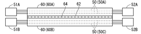
- FIG. 2 is a perspective view showing the protection units 60A and 60B.
- FIG. 3 is a plan view showing the protection units 60A and 60B.
- FIG. 2 shows a state in which the wiring members 50A and 50B are passed through the protection portions 60A and 60B.
- the protection units 60A and 60B are connected by a connecting unit 62.
- the protective portions 60A and 60B are formed in a tubular shape.
- the protective portions 60A and 60B may be a cylinder, an elliptical cylinder, or a square cylinder.
- the connecting portion 62 is a portion that connects a plurality of protective portions 60A and 60B.
- the connecting portion 62 connects the two protective portions 60A and 60B in a parallel state.
- Three or more protective units may be provided.
- the connecting portion may be provided as a portion for connecting adjacent ones among a plurality of protective portions arranged in parallel.
- a break line 64 that is easily broken is formed in the connecting portion 62.
- the breaking line 64 is a linear portion that is easier to break than other portions.
- the break line 64 may be a portion where elongated slits or holes are intermittently formed.
- the breaking line 64 may be a groove-shaped portion.
- the breaking line 64 is formed between the protective portions 60A and 60B so as to extend along the axial direction of the protective portions 60A and 60B. Therefore, when the connecting portion 62 is broken at the breaking line 64, the plurality of protective portions 60A and 60B are separated entirely or partially along the extending direction thereof.
- the configuration in which the protection units 60A and 60B are connected in a easily separable manner is not limited to the above example.
- the protective portions 60A and 60B may be bound by a binding member such as a string or tape, and the string or tape may be cut at the time of separation.
- the binding member is partially provided in the extending direction of the protective portion 60A, the protective portions 60A and 60B can be easily separated by cutting the binding member or the like.
- the connecting body of the protective portions 60A and 60B as described above may be formed by extrusion molding of a resin or the like. Depending on the type of resin, the protective portions 60A and 60B may be formed as flexible bendable protective portions.
- the wiring members 50A and 50B When the wiring members 50A and 50B are inserted into the protective portions 60A and 60B, the wiring members 50A and 50B are protected by the protective portions 60A and 60B.
- the connectors 51A and 51B at one end of the wiring members 50A and 50B are connected to the common area control unit 32. Therefore, the connectors 51A and 51B can be arranged side by side relatively close to each other. Of the plurality of protective portions 60A and 60B, the connectors 51A and 51B sides may remain connected by the connecting portion 62.
- the connectors 52A and 52B at the other ends of the wiring members 50A and 50B are connected to other devices 40A and 40B. If the devices 40A and 40B are relatively close to each other, the connectors 52A and 52B of the plurality of protective portions 60A and 60B may also be left connected by the connecting portion 62. When the devices 40A and 40B are relatively separated, as shown in FIG. 4, the connecting portion 62 may be broken at the portion of the plurality of protective portions 60A and 60B on the connector 52A and 52B side. In this case, the plurality of protection units 60A and 60B are arranged with respect to the automobile 10 so as to be separated on the way from the area control unit 32 to the devices 40A and 40B and to face in different directions.
- the lengths of the protective portions 60A and 60B may be the same or different.
- the protection units 60A and 60B are cut or the like according to the distances, and the lengths of the protection units 60A and the protection units 60B are different. You may be.
- the plurality of protective units 60A and 60B may include a common wiring member that is commonly wired in the vehicle and a selective wiring member that is selectively wired in the vehicle.
- the common wiring member is a wiring member that is wired to the vehicle regardless of the difference in the grade of the automobile, the difference in the optional equipment (either the initial optional equipment or the ex post optional equipment), etc. ..
- Such common wiring members are collectively protected by the protection unit 60A.
- the common wiring member may be at least one of a wiring member for an airbag and a wiring member for a brake, which are commonly equipped regardless of the difference in the grade of the automobile.
- wiring members for airbags such as curtain airbags, which are equipped as optional equipment, may be selected wiring members.
- the brake itself is different depending on the grade, and the wiring member for the brake may be different accordingly.
- the wiring member for the brake may also be a selective wiring member.
- the selected wiring member is a wiring member that may or may not be wired in the vehicle due to differences in the grade of the automobile, differences in optional equipment, and the like. Such a selective wiring member is put together separately from the common wiring member and protected by the protection unit 60B.
- the selected wiring member includes at least one of, for example, a wiring member for a headlamp, a wiring member for an air conditioner, a wiring member for indoor lighting, and a wiring member for a speaker.
- headlamps such as halogen lamps, HID (high-intensity discharge lamps) lamps, and LED (light emission diode) lamps
- air conditioners such as manual air conditioners, auto air conditioners, and cooling capacities
- the wiring members will differ depending on the selected content.
- indoor lighting there are differences in lighting locations, etc., and it is assumed that the wiring members will differ depending on the selected content.
- speakers there are differences in the speaker installation position, number of speakers, etc., and it is assumed that the wiring members will differ depending on the selected content.
- Wiring members include wiring members that are connected to devices that are generally considered to be related to driving or safety, such as airbags and brakes, and devices that are generally considered to be body systems, such as headlamps, air conditioners, interior lighting, and speakers. It may be separated from the wiring member to be connected and protected by a protective unit.
- the wiring member 50A is a common wiring member
- the wiring member 50B is a selective wiring member
- the protection unit 60A protects the wiring member 50A for one device 40A
- the protection unit 60B protects the wiring member for one device 40B.
- each of the protection units 60A and 60B may protect the wiring members for a plurality of devices.
- the protection unit 60A protects the wiring members 150A, 150B, 150C for the plurality of devices 140A, 140B, 140C.
- One end of the wiring members 150A, 150B, and 150C is connected to a common connector 151A, and is connected to the area control unit 32 via the connector 151A.
- the other ends of the wiring members 150A, 150B, 150C are connected to separate connectors 152A, 152B, 152C, and are separately connected to the devices 140A, 140B, 140C, respectively.
- the protection unit 60B protects the wiring members 150D and 150E for a plurality of devices 140D and 140E.
- One end of the wiring members 150D and 150E is connected to a common connector 151D, and is connected to the area control unit 32 via the connector 151D.
- the other ends of the wiring members 150D and 150E are connected to separate connectors 152D and 152E, and are separately connected to the devices 140D and 140E, respectively.
- one end of the plurality of wiring members 150A, 150B, 150C, 150D, 150E is connected to the connectors 151A, 152B in a state of being separated among at least the plurality of protection portions 60A, 60B. Further, the other ends of the plurality of wiring members 150A, 150B, 150C, 150D, 150E are separated from at least the plurality of protection portions 60A, 60B, that is, the other ends of the wiring members 150A, 150B, 150C. It is connected to the connectors 152A, 152B, 152C, 152D, 152E in a state of being separated into a portion and the other end portion of the wiring members 150D, 150E.
- the plurality of wiring members 150A, 150B, 150C are collectively protected by the protection unit 60A.
- the plurality of wiring members 150D and 150E are collectively protected by the protection unit 60B separately from the wiring members 150A, 150B and 150C.
- the wiring system 20 is prepared.
- the protective portions 60A and 60B are connected via the connecting portion 62.
- the wiring members 50A and 50B are separately protected by the protection portions 60A and 60B. It is assumed that the protection unit 60A protects the wiring member 50A as a common wiring member, and the protection unit 60B protects the wiring member 50B as a selection wiring member.
- This wiring system 20 is arranged in the vehicle 12 (step (a)).
- the connectors 51A and 51B are connected to the area control unit 32, and the connectors 52A and 52B are connected to the devices 40A and 40B.
- the wiring members 50A and 50B themselves are also fixed to the vehicle 12 by using a clamp or the like for fixing the electric wire, if necessary. In this case, only the wiring member 50A is fixed to the vehicle 12, and the wiring member 50B does not have to be fixed to the vehicle 12.
- the protective portions 60A and 60B may also be fixed to the vehicle 12 by using a clamp for fixing the electric wire or the like, if necessary. In this case, only the protection unit 60A is fixed to the vehicle 12, and the protection unit 60B does not have to be fixed to the vehicle. For example, when a clamp having a binding band is used, the binding band may penetrate the connecting portion 62 and be wound only around the protective portion 60A.
- step (a) removal of the wiring member 50B, change to another wiring member, or the like may be requested.
- the protective portions 60A and 60B are separated. When there are three or more protective portions, a part of them and the rest may be separated.
- the protection unit 60B and the wiring member 50B protected by the protection unit 60B are removed from the vehicle while the protection unit 60A and the wiring member 50A protected by the protection unit 60A are left in the vehicle 12.
- Step (b) The connectors 51B and 52B are removed from the area control unit 32 and the device 40B.
- another wiring member 50C is arranged along the wiring member 50A as needed.
- the wiring member 50C may be protected by another protection unit 60A.
- a connector 51C is connected to one end of the wiring member 50C, and is connected to the area control unit 32 via the connector 51C.
- a connector 52C is connected to the other end of the wiring member 50C, and is connected to a new device 40C via the connector 52C.
- the wiring member 50C or the protection unit 60C may be combined with the protection unit 60A.
- a binding member 66 such as an adhesive tape or a binding band may be wound around the protective portions 60A and 60C and combined. The binding member 66 may be attached to a portion of the protective portions 60A and 60B in the longitudinal direction thereof.
- a plurality of wiring members protected by the protection unit 60B and a plurality of wiring members protected by the protection unit 60C may be partially different and the rest may be common. ..
- a plurality of wiring members protected by the protection unit 60B to which another wiring member is added may be a plurality of wiring members protected by the protection unit 60C.
- a part of the plurality of wiring members protected by the protection unit 60B may be deleted or changed to another wiring member to be a plurality of wiring members protected by the protection unit 60C. ..
- the wiring member 50A as the selection wiring member can be easily changed to another wiring member 50C while the wiring member 50A as the common wiring member is left in the initial state.
- the wiring system 220 modified in that the protection unit 60B and the wiring member 50B are removed from the wiring system 20 can be easily manufactured.
- the wiring system 320 modified in that the protection unit 60C and the wiring member 50C are arranged in place of the protection unit 60B and the wiring member 50B can be easily manufactured.
- the manufacturing method of the wiring system 20 or the modified wiring systems 220 and 320 configured as described above since the plurality of protection units 60A and 60B are connected in a separable manner via the connection unit 62, It is easy to arrange the plurality of wiring members 50A and 50B together in the vehicle 12. Further, by separating the plurality of protective portions 60A and 60B, it is possible to easily replace or delete the plurality of wiring members 50A and 50B.
- the plurality of wiring members 50A and 50B include a common wiring member (wiring member 50A) and a selective wiring member (wiring member 50B), and these are protected by separate protection units 60A and 60B. Therefore, the selective wiring member (wiring member 50A) can be easily removed while the common wiring member (wiring member 50A) remains assembled in the vehicle 12, and the selective wiring member (wiring member 50A) can be easily removed as needed. 50A) can be easily replaced with another wiring member 50C.
- the plurality of protective portions 60A and 60B can be easily divided along the breaking line 64.
- the ends of the plurality of wiring members 50A and 50B are connected to the connectors 51A, 52A, 51B, 52B and the like in a state of being separated by at least the protection portions 60A and 60B. Therefore, the connector connection and disconnection to the area control unit 32 and the devices 40A and 40B to be connected to the protection units 60A and 60B can be easily performed.
Landscapes
- Engineering & Computer Science (AREA)
- Architecture (AREA)
- Civil Engineering (AREA)
- Structural Engineering (AREA)
- Mechanical Engineering (AREA)
- General Engineering & Computer Science (AREA)
- Manufacturing & Machinery (AREA)
- Details Of Indoor Wiring (AREA)
- Installation Of Indoor Wiring (AREA)
- Protection Of Pipes Against Damage, Friction, And Corrosion (AREA)
- Insulated Conductors (AREA)
Priority Applications (2)
| Application Number | Priority Date | Filing Date | Title |
|---|---|---|---|
| US17/621,439 US20220355748A1 (en) | 2019-07-02 | 2020-06-11 | Wiring system and method for manufacturing changed wiring system |
| CN202080047577.1A CN114026759B (zh) | 2019-07-02 | 2020-06-11 | 配线系统及变更的配线系统的制造方法 |
Applications Claiming Priority (2)
| Application Number | Priority Date | Filing Date | Title |
|---|---|---|---|
| JP2019123552A JP7346943B2 (ja) | 2019-07-02 | 2019-07-02 | 配線システム及び変更された配線システムの製造方法 |
| JP2019-123552 | 2019-07-02 |
Publications (1)
| Publication Number | Publication Date |
|---|---|
| WO2021002170A1 true WO2021002170A1 (ja) | 2021-01-07 |
Family
ID=74100574
Family Applications (1)
| Application Number | Title | Priority Date | Filing Date |
|---|---|---|---|
| PCT/JP2020/022969 Ceased WO2021002170A1 (ja) | 2019-07-02 | 2020-06-11 | 配線システム及び変更された配線システムの製造方法 |
Country Status (4)
| Country | Link |
|---|---|
| US (1) | US20220355748A1 (enExample) |
| JP (1) | JP7346943B2 (enExample) |
| CN (1) | CN114026759B (enExample) |
| WO (1) | WO2021002170A1 (enExample) |
Families Citing this family (1)
| Publication number | Priority date | Publication date | Assignee | Title |
|---|---|---|---|---|
| JP7622658B2 (ja) * | 2022-01-14 | 2025-01-28 | 株式会社オートネットワーク技術研究所 | 配線システム |
Citations (4)
| Publication number | Priority date | Publication date | Assignee | Title |
|---|---|---|---|---|
| JPS61141918U (enExample) * | 1985-02-25 | 1986-09-02 | ||
| JPH0687101U (ja) * | 1993-05-28 | 1994-12-20 | 昭和飛行機工業株式会社 | ワイヤリングハーネスの取付構造 |
| JP2012249428A (ja) * | 2011-05-27 | 2012-12-13 | Yazaki Corp | 合体ワイヤハーネス |
| JP2019102305A (ja) * | 2017-12-04 | 2019-06-24 | 矢崎総業株式会社 | 車両用の回路体 |
Family Cites Families (25)
| Publication number | Priority date | Publication date | Assignee | Title |
|---|---|---|---|---|
| US4272689A (en) * | 1978-09-22 | 1981-06-09 | Harvey Hubbell Incorporated | Flexible wiring system and components therefor |
| JPS5874719U (ja) * | 1981-11-16 | 1983-05-20 | 株式会社フジクラ | フロアケ−ブル |
| JP3682366B2 (ja) * | 1997-12-26 | 2005-08-10 | 古河電気工業株式会社 | ワイヤハーネス及びその製造方法 |
| JP2003100155A (ja) * | 2001-09-21 | 2003-04-04 | Yazaki Corp | ワイヤーハーネス |
| US7039282B2 (en) * | 2004-06-30 | 2006-05-02 | Corning Cable Systems Llc | Optical fiber array with an intermittent profile and method for manufacturing the same |
| US20060045443A1 (en) * | 2004-08-30 | 2006-03-02 | Blazer Bradley J | Fiber optic ribbons having one or more preferential tear portions and method of making the same |
| US20090272576A1 (en) * | 2008-04-30 | 2009-11-05 | Ise Corporation | Vehicle High Power Cable Fastening System and Method |
| JP5618632B2 (ja) * | 2010-05-31 | 2014-11-05 | 矢崎総業株式会社 | ワイヤハーネス |
| JP5811892B2 (ja) * | 2012-02-24 | 2015-11-11 | 住友電装株式会社 | ワイヤハーネス用の外装材 |
| JP5957286B2 (ja) * | 2012-05-09 | 2016-07-27 | 矢崎総業株式会社 | ワイヤハーネス止水構造 |
| JP2014022310A (ja) * | 2012-07-23 | 2014-02-03 | Sumitomo Electric Ind Ltd | 同軸電線ハーネス |
| JP2014107917A (ja) * | 2012-11-27 | 2014-06-09 | Sumitomo Wiring Syst Ltd | ワイヤーハーネス |
| US9026311B1 (en) * | 2013-03-13 | 2015-05-05 | Tuson Rv Brakes, Llc | Trailer sway detection and method for reducing trailer sway utilizing trailer brakes |
| JP2014230321A (ja) * | 2013-05-20 | 2014-12-08 | 住友電装株式会社 | ワイヤーハーネス |
| JP6263501B2 (ja) * | 2015-06-12 | 2018-01-17 | 矢崎総業株式会社 | ワイヤーハーネス |
| DE112016003533B4 (de) * | 2015-08-05 | 2024-10-02 | Yazaki Corporation | Kabelbaum-System und Kabelbaum |
| CN110226206B (zh) * | 2016-10-31 | 2020-10-27 | 住友电气工业株式会社 | 带操作部的线缆 |
| JP6652036B2 (ja) * | 2016-11-07 | 2020-02-19 | 株式会社オートネットワーク技術研究所 | ワイヤーハーネス及びワイヤーハーネスの製造方法 |
| JP6743718B2 (ja) * | 2017-01-31 | 2020-08-19 | 日立金属株式会社 | ケーブルの止水構造、ワイヤハーネス、及びワイヤハーネスの製造方法 |
| JP2019051817A (ja) * | 2017-09-15 | 2019-04-04 | 本田技研工業株式会社 | 車両 |
| JP6453970B1 (ja) * | 2017-10-05 | 2019-01-16 | 株式会社フジクラ | 間欠連結型光ファイバテープ、及び、間欠連結型光ファイバテープの製造方法 |
| JP7020049B2 (ja) * | 2017-10-16 | 2022-02-16 | 住友電気工業株式会社 | ダイス、および、光ファイバテープ心線の製造方法 |
| JP6973341B2 (ja) * | 2018-09-25 | 2021-11-24 | 株式会社オートネットワーク技術研究所 | ワイヤハーネス |
| WO2020121390A1 (ja) * | 2018-12-11 | 2020-06-18 | 株式会社オートネットワーク技術研究所 | ジョイントコネクタ |
| US11038325B2 (en) * | 2019-07-23 | 2021-06-15 | The Boeing Company | Aircraft electrical racetrack systems and methods |
-
2019
- 2019-07-02 JP JP2019123552A patent/JP7346943B2/ja active Active
-
2020
- 2020-06-11 WO PCT/JP2020/022969 patent/WO2021002170A1/ja not_active Ceased
- 2020-06-11 CN CN202080047577.1A patent/CN114026759B/zh active Active
- 2020-06-11 US US17/621,439 patent/US20220355748A1/en not_active Abandoned
Patent Citations (4)
| Publication number | Priority date | Publication date | Assignee | Title |
|---|---|---|---|---|
| JPS61141918U (enExample) * | 1985-02-25 | 1986-09-02 | ||
| JPH0687101U (ja) * | 1993-05-28 | 1994-12-20 | 昭和飛行機工業株式会社 | ワイヤリングハーネスの取付構造 |
| JP2012249428A (ja) * | 2011-05-27 | 2012-12-13 | Yazaki Corp | 合体ワイヤハーネス |
| JP2019102305A (ja) * | 2017-12-04 | 2019-06-24 | 矢崎総業株式会社 | 車両用の回路体 |
Also Published As
| Publication number | Publication date |
|---|---|
| CN114026759B (zh) | 2024-10-25 |
| US20220355748A1 (en) | 2022-11-10 |
| CN114026759A (zh) | 2022-02-08 |
| JP7346943B2 (ja) | 2023-09-20 |
| JP2021009816A (ja) | 2021-01-28 |
Similar Documents
| Publication | Publication Date | Title |
|---|---|---|
| JP6490624B2 (ja) | ワイヤハーネス | |
| US10661729B2 (en) | Circuit body for vehicle | |
| US10583791B2 (en) | Wire harness | |
| JP7239264B2 (ja) | 車両用の回路体 | |
| US9776558B2 (en) | Flasher vehicle interface module | |
| CN109866706B (zh) | 车辆电路体 | |
| CN109866705B (zh) | 车辆电路体和车辆电路体制造方法 | |
| WO2017022850A1 (ja) | ワイヤハーネスシステム、及び、ワイヤハーネス | |
| JPWO2017222076A1 (ja) | 車両用回路体 | |
| KR20090077041A (ko) | 배선 시스템 | |
| US10300867B2 (en) | Wire harness with trunk line distributor | |
| JP7040963B2 (ja) | ワイヤハーネスの製造方法、及び、ワイヤハーネス | |
| WO2021002170A1 (ja) | 配線システム及び変更された配線システムの製造方法 | |
| US9440598B2 (en) | Wiring harness assembly for vehicle including source splice overlay | |
| EP1038728A2 (en) | Headlight circuit for an automobile | |
| US20090251908A1 (en) | Integrated headlight assembly for tactical vehicles | |
| US12227121B1 (en) | Harness for emergency vehicle lights | |
| JP2005295768A (ja) | 電源分配システム | |
| JP4880216B2 (ja) | ワイヤハーネスの組立方法 | |
| JPH08258642A (ja) | 自動車の配線構造 | |
| WO2013176284A1 (ja) | ワイヤーハーネスシステム |
Legal Events
| Date | Code | Title | Description |
|---|---|---|---|
| 121 | Ep: the epo has been informed by wipo that ep was designated in this application |
Ref document number: 20828946 Country of ref document: EP Kind code of ref document: A1 |
|
| NENP | Non-entry into the national phase |
Ref country code: DE |
|
| 122 | Ep: pct application non-entry in european phase |
Ref document number: 20828946 Country of ref document: EP Kind code of ref document: A1 |