WO2020241324A1 - リアクトル - Google Patents
リアクトル Download PDFInfo
- Publication number
- WO2020241324A1 WO2020241324A1 PCT/JP2020/019529 JP2020019529W WO2020241324A1 WO 2020241324 A1 WO2020241324 A1 WO 2020241324A1 JP 2020019529 W JP2020019529 W JP 2020019529W WO 2020241324 A1 WO2020241324 A1 WO 2020241324A1
- Authority
- WO
- WIPO (PCT)
- Prior art keywords
- case
- union
- portions
- protrusion
- reactor
- Prior art date
- Legal status (The legal status is an assumption and is not a legal conclusion. Google has not performed a legal analysis and makes no representation as to the accuracy of the status listed.)
- Ceased
Links
Images






Classifications
-
- H—ELECTRICITY
- H01—ELECTRIC ELEMENTS
- H01F—MAGNETS; INDUCTANCES; TRANSFORMERS; SELECTION OF MATERIALS FOR THEIR MAGNETIC PROPERTIES
- H01F37/00—Fixed inductances not covered by group H01F17/00
-
- H—ELECTRICITY
- H01—ELECTRIC ELEMENTS
- H01F—MAGNETS; INDUCTANCES; TRANSFORMERS; SELECTION OF MATERIALS FOR THEIR MAGNETIC PROPERTIES
- H01F27/00—Details of transformers or inductances, in general
- H01F27/02—Casings
-
- H—ELECTRICITY
- H01—ELECTRIC ELEMENTS
- H01F—MAGNETS; INDUCTANCES; TRANSFORMERS; SELECTION OF MATERIALS FOR THEIR MAGNETIC PROPERTIES
- H01F27/00—Details of transformers or inductances, in general
- H01F27/02—Casings
- H01F27/022—Encapsulation
-
- H—ELECTRICITY
- H01—ELECTRIC ELEMENTS
- H01F—MAGNETS; INDUCTANCES; TRANSFORMERS; SELECTION OF MATERIALS FOR THEIR MAGNETIC PROPERTIES
- H01F27/00—Details of transformers or inductances, in general
- H01F27/06—Mounting, supporting or suspending transformers, reactors or choke coils not being of the signal type
-
- H—ELECTRICITY
- H01—ELECTRIC ELEMENTS
- H01F—MAGNETS; INDUCTANCES; TRANSFORMERS; SELECTION OF MATERIALS FOR THEIR MAGNETIC PROPERTIES
- H01F27/00—Details of transformers or inductances, in general
- H01F27/24—Magnetic cores
- H01F27/26—Fastening parts of the core together; Fastening or mounting the core on casing or support
-
- H—ELECTRICITY
- H01—ELECTRIC ELEMENTS
- H01F—MAGNETS; INDUCTANCES; TRANSFORMERS; SELECTION OF MATERIALS FOR THEIR MAGNETIC PROPERTIES
- H01F27/00—Details of transformers or inductances, in general
- H01F27/24—Magnetic cores
- H01F27/26—Fastening parts of the core together; Fastening or mounting the core on casing or support
- H01F27/266—Fastening or mounting the core on casing or support
-
- H—ELECTRICITY
- H01—ELECTRIC ELEMENTS
- H01F—MAGNETS; INDUCTANCES; TRANSFORMERS; SELECTION OF MATERIALS FOR THEIR MAGNETIC PROPERTIES
- H01F27/00—Details of transformers or inductances, in general
- H01F27/28—Coils; Windings; Conductive connections
- H01F27/30—Fastening or clamping coils, windings, or parts thereof together; Fastening or mounting coils or windings on core, casing, or other support
- H01F27/306—Fastening or mounting coils or windings on core, casing or other support
-
- H—ELECTRICITY
- H01—ELECTRIC ELEMENTS
- H01F—MAGNETS; INDUCTANCES; TRANSFORMERS; SELECTION OF MATERIALS FOR THEIR MAGNETIC PROPERTIES
- H01F41/00—Apparatus or processes specially adapted for manufacturing or assembling magnets, inductances or transformers; Apparatus or processes specially adapted for manufacturing materials characterised by their magnetic properties
- H01F41/02—Apparatus or processes specially adapted for manufacturing or assembling magnets, inductances or transformers; Apparatus or processes specially adapted for manufacturing materials characterised by their magnetic properties for manufacturing cores, coils, or magnets
- H01F41/04—Apparatus or processes specially adapted for manufacturing or assembling magnets, inductances or transformers; Apparatus or processes specially adapted for manufacturing materials characterised by their magnetic properties for manufacturing cores, coils, or magnets for manufacturing coils
- H01F41/12—Insulating of windings
- H01F41/127—Encapsulating or impregnating
-
- H—ELECTRICITY
- H01—ELECTRIC ELEMENTS
- H01F—MAGNETS; INDUCTANCES; TRANSFORMERS; SELECTION OF MATERIALS FOR THEIR MAGNETIC PROPERTIES
- H01F27/00—Details of transformers or inductances, in general
- H01F27/02—Casings
- H01F27/025—Constructional details relating to cooling
Definitions
- Patent Documents 1 and 2 disclose a reactor including a coil, a magnetic core, a case for accommodating a combination of the coil and the magnetic core, and a sealing resin portion filled in the case and covering the outer periphery of the combination. To do.
- Patent Document 1 discloses a structure in which a strip-shaped stay presses an outer core portion of the magnetic core, which is arranged outside the winding portion of the coil, toward the bottom surface side of the case. The stay is arranged on the opening side surface of the case in the outer core portion. Both ends of the stay are screwed to the case.
- the reactor of this disclosure is A coil with a pair of windings arranged in parallel, Magnetic cores arranged inside and outside the winding portion, A holding member that defines the mutual position of the coil and the magnetic core, A case for accommodating the coil, the magnetic core, and the union including the holding member, and A sealing resin portion filled in the case is provided.
- the case includes a bottom plate portion on which the union is placed, a side wall portion surrounding the union, and an opening facing the bottom plate.
- the union is housed in the case so that the axial direction of each of the winding portions is along the depth direction of the case.
- the magnetic core includes an outer core portion that is outside the winding portion and is arranged on the opening side.
- the holding member includes an outer wall portion that covers at least a part of the outer peripheral surface of the outer core portion, and at least one protrusion that projects from the outer wall portion toward the inner peripheral surface of the side wall portion. The protrusion is embedded in the sealing resin portion.
- FIG. 1 is a schematic partial cross-sectional view of the reactor according to the first embodiment cut in a plane parallel to the depth direction and the length direction of the case.
- FIG. 2 is a schematic plan view of the reactor according to the first embodiment in a plan view in the depth direction of the case.
- FIG. 3 is a schematic partial cross-sectional view of the reactor according to the first embodiment cut in a plane parallel to the depth direction and the width direction of the case.
- FIG. 4 is an exploded view illustrating the manufacturing process of the union shown in FIG.
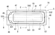
- FIG. 5A is a schematic plan view of the reactor according to the second embodiment.
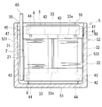
- FIG. 5B is a schematic partial cross-sectional view of the reactor according to the second embodiment as viewed from the side.
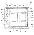
- FIG. 5C is a schematic partial cross-sectional view of the reactor according to the second embodiment as viewed from the front.
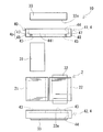
- FIG. 6 is a schematic rear view of the union body provided in the reactor according to the second embodiment.
- FIG. 7 is a schematic exploded side view for explaining the manufacturing process of the union provided in the reactor according to the second embodiment.
- FIG. 8A is a diagram showing a process of forming the sealing resin portion, and is a schematic plan view of the union and the case as viewed from above.
- FIG. 8B is a diagram showing a process of forming the sealing resin portion, and is a schematic partial cross-sectional view of the union and the case as viewed from the side.
- FIG. 9A is a schematic plan view of the reactor according to the third embodiment.
- FIG. 9B is a schematic partial cross-sectional view of the reactor according to the third embodiment as viewed from the side.
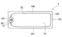
- FIG. 10 is a schematic plan view of a case provided in the reactor according to the third embodiment.
- the union vibrates. Further, when the reactor is an in-vehicle part or the like, the union vibrates due to external vibration during use.
- One of the purposes of the present disclosure is to provide a reactor capable of reducing the amplitude when the union vibrates.
- the reactor of the present disclosure can reduce the amplitude when the union vibrates.
- the reactor according to the embodiment of the present disclosure is A coil with a pair of windings arranged in parallel, Magnetic cores arranged inside and outside the winding portion, A holding member that defines the mutual position of the coil and the magnetic core, A case for accommodating the coil, the magnetic core, and the union including the holding member, and A sealing resin portion filled in the case is provided.
- the case includes a bottom plate portion on which the union is placed, a side wall portion surrounding the union, and an opening facing the bottom plate.
- the union is housed in the case so that the axial direction of each of the winding portions is along the depth direction of the case.
- the magnetic core includes an outer core portion that is outside the winding portion and is arranged on the opening side.
- the holding member includes an outer wall portion that covers at least a part of the outer peripheral surface of the outer core portion, and at least one protrusion that projects from the outer wall portion toward the inner peripheral surface of the side wall portion. The protrusion is embedded in the sealing resin portion.
- the reactor of the present disclosure is provided with a protrusion on the opening side of the case, the amplitude when the union vibrates in a direction intersecting with the depth direction of the case is higher than that in the case without the protrusion. Can be made smaller. There are two reasons for this.
- the direction in which the case intersects in the depth direction may be referred to as an intersection direction.
- the amplitude of the region located on the opening side of the case in the union becomes larger than the amplitude of the region located on the bottom plate side of the case in the union. easy.
- the protrusions locally narrow the distance between the outer peripheral surface of the union and the inner peripheral surface of the side wall of the case on the opening side of the case. The narrow spacing limits the amount of displacement of the union in the case in the crossing direction.
- the contact area becomes smaller when the outer peripheral surface of the union and the inner peripheral surface of the side wall of the case come into contact with each other, as compared with the case where the protrusions are not provided. Therefore, it is difficult for vibration to be transmitted between the union and the case.
- Examples thereof include a form in which the inner peripheral surface is inclined so as to spread from the bottom plate portion side toward the opening side.
- the distance between the outer peripheral surface of the union and the inner peripheral surface of the side wall of the case tends to be large on the opening side of the case.
- the protrusions ensure that the spacing is narrowed.
- the above-mentioned form is also excellent in manufacturability in that the union can be easily stored in the case in the reactor manufacturing process and the case can be easily removed in the case manufacturing process.
- the first rectangle containing the union is virtually taken, and the size along the long side direction of the first rectangle is defined as the long side length, and the first rectangle is defined as the long side length.
- the size along the short side direction of is defined as the short side length.
- the size of the union along the depth direction is defined as the height of the union. Examples thereof include a form in which at least one of the ratio of the height to the long side length and the ratio of the height to the short side length is more than 1.0.
- the shape of the union in the above form is such that the amplitude of the region on the opening side of the case in the union tends to increase when vibrating in the above-mentioned crossing direction. Even in such a form, the amplitude can be reduced by the protrusion.
- a second rectangle including the outer wall portion is virtually taken.
- the outer wall portion has a first surface along the long side direction of the second rectangle and a second surface along the short side direction of the second rectangle.
- the holding member include a first protrusion provided on the first surface and a second protrusion provided on the second surface.
- the shape of at least one of the protrusions may be a spherical shape.
- the state where the protrusion and the inner peripheral surface of the side wall of the case are in contact is the point contact. Therefore, the contact area between the protrusion and the inner peripheral surface is small. From this point, vibration is less likely to be transmitted between the union and the case.
- the holding member includes a plurality of the protrusions. At least one of the protrusions may be in contact with the inner peripheral surface.
- the union includes an end face facing the bottom plate portion and a leg portion.
- the leg portion include a form in which the leg portion projects from the end face toward the bottom plate portion.
- the contact area between the end face of the union and the inner bottom surface of the bottom plate portion of the case is smaller than that in the case where the legs are not provided. Therefore, vibration is less likely to be transmitted between the union and the case.
- 1 and 3 are partial cross-sectional views of the case 5 and the sealing resin portion 6 provided in the reactor 1 cut in a plane parallel to the depth direction of the case 5.
- the union 10 of FIGS. 1 and 3 shows an appearance, not a cross section.
- the cross-sectional view of FIG. 1 corresponds to a cross-sectional view cut along the cutting lines I-I shown in FIG.
- the cross-sectional view of FIG. 3 corresponds to a cross-sectional view cut along the cutting lines III-III shown in FIG.
- FIG. 4 shows an exploded state of the union body 10 provided in the reactor 1 without the mold resin portion 8 described later.
- the reactor 1 includes a coil 2, a magnetic core 3, a holding member 4, a case 5, and a sealing resin portion 6.
- the coil 2 has a pair of winding portions 21 and 22 arranged in parallel.
- the magnetic core 3 is arranged inside and outside the winding portions 21 and 22.
- the holding member 4 defines the mutual position between the coil 2 and the magnetic core 3.
- the case 5 houses the union body 10 including the coil 2, the magnetic core 3, and the holding member 4.
- the case 5 includes a bottom plate portion 51, a side wall portion 52, and an opening portion 55.
- the union body 10 is placed on the bottom plate portion 51.
- the side wall portion 52 surrounds the union body 10.
- the opening 55 opens facing the bottom plate 51.
- the sealing resin portion 6 is filled in the case 5. In FIG. 2, the sealing resin portion 6 is omitted.
- the union body 10 is housed in the case 5 so that the axial directions of the winding portions 21 and 22 are along the depth direction of the case 5.
- this arrangement form is referred to as an upright type.
- the holding member 41 arranged on the opening 55 side of the case 5 in the union body 10 includes at least one protruding portion 4p protruding toward the inner peripheral surface 520 of the side wall portion 52 of the case 5. ..
- the protrusion 4p is embedded in the sealing resin portion 6.
- the protrusion 4p contributes to locally narrowing the distance between the outer peripheral surface 100 of the union body 10 and the inner peripheral surface 520 of the case 5 on the opening 55 side of the case 5.
- Such a protrusion 4p limits the range in which the union body 10 is displaced in the above-mentioned crossing direction in the case 5.
- the configuration of the reactor 1 of the first embodiment will be described in detail.
- the bottom plate portion 51 side of the case 5 is on the bottom, and the side opposite to the bottom plate portion 51 side, that is, the opening 55 side is on the top.
- the depth direction of the case 5 is this vertical direction.
- the vertical direction of the paper surface may be referred to as the height direction.
- the direction orthogonal to the height direction and along the long side portions 541 and 542 shown in FIG. 2 on the side wall portion 52 of the case 5 is defined as the length direction.
- the long side portions 541 and 542 are formed on the side wall portion 52 when the smallest rectangle including the opening 55 is virtually taken in a state where the case 5 is viewed in a plan view in the depth direction.
- the short side portions 531 and 532 which will be described later, are portions of the side wall portion 52 along the short side direction of the virtual rectangle.
- the plan view refers to a state viewed from the depth direction of the case 5.
- the width direction is a direction orthogonal to the height direction and is along the short side portions 531 and 532 of the side wall portion 52 of the case 5.
- the length direction is the left-right direction of the paper in FIGS. 1 and 2.
- the width direction is the vertical direction of the paper surface in FIG. 2, and the horizontal direction of the paper surface in FIG.
- the height direction, the length direction, and the width direction are similarly applied to the second and third embodiments and FIGS. 5A to 10 described later.
- the union body 10 of this example includes a mold resin portion 8 described later in addition to the coil 2, the magnetic core 3, and the holding member 4.
- the appearance of the union body 10 of this example is a rectangular parallelepiped shape.
- the length of the union 10 is larger than the width.
- the height of the union body 10 is larger than the width and is substantially equal to the length.
- the ratio of height to length is about 1.0 and the ratio of height to width is more than 1.0.
- the length, width, and height of the union 10 are as follows. Virtually a rectangle containing the union body 10 in a plan view from the axial direction of the winding portions 21 and 22 or in a plan view from the depth direction of the case 5 when the union body 10 is housed in the case 5. Take.
- the length of the union body 10 is a size along the long side direction of the virtual rectangle, that is, the length of the long side.
- the width of the union body 10 is a size along the short side direction of the virtual rectangle, that is, the short side length.
- the height of the union body 10 is a size along the axial direction or the depth direction.
- the ratio of height to length and the ratio of height to width are less than 1.0 and one of them is more than 1.0, the surface arranged on the inner bottom surface 510 side of the case 5 in the union body 10, here the end surface 105.
- the height is large. It can be said that such a union body 10 has a vertically long shape. It can be said that the vertically long union body 10 easily vibrates in the above-mentioned crossing direction. Further, when vibrating in the crossing direction, it can be said that the amplitude of the region on the opening 55 side of the case 5 tends to increase in the union body 10.
- the larger the value of the above ratio the larger the amplitude tends to be.
- the volume of the union body 10 is constant, the larger the value of the above ratio, the smaller the area of the end face 105 of the union body 10 tends to be.
- the area of the inner bottom surface 510 of the case 5 tends to be small.
- the installation area tends to be small. From the viewpoint of miniaturization of the installation area, for example, at least one of the above-mentioned ratio of height to length and ratio of height to width is 1.2 or more, 1.5 or more, 1.8 or more, 2.0. The above may be sufficient. In the reactor 1 of the first embodiment, even if the union body 10 has a vertically long shape, the above-mentioned amplitude is reduced by the protrusion 4p.
- At least one of the above-mentioned ratio of height to length and ratio of height to width may be 5.0 or less, 4.5 or less, 4.0 or less.
- the height to width ratio is 5.0 or less.
- the coil 2 has a pair of winding portions 21, 22.
- the winding portions 21 and 22 are configured by winding the windings in a spiral shape. Both winding portions 21 and 22 are arranged in parallel so that their axial directions are parallel to each other. In the above-mentioned case storage state, the axial directions of both winding portions 21 and 22 coincide with the height direction.
- both winding portions 21 and 22 are composed of one continuous winding.
- the winding is bent and folded back on the first end surface side of the winding portion 21 to form the other winding portion 22.
- each winding portion 21 and 22 may be composed of separate windings.
- the end portions of the windings are connected to each other on the first end surface side of each winding portion 21 and 22. Joining methods such as welding, crimping, soldering, and brazing can be used for this connection.
- FIG. 1 and the like show only the winding portions 21 and 22, and the end portions of the winding are omitted.
- Examples of the winding include a conductor wire and a coated wire having an insulating coating.
- Examples of the constituent material of the conductor wire include copper and the like.
- Examples of the constituent material of the insulating coating include resins such as polyamide-imide.
- Examples of the covered wire include a covered flat wire having a rectangular cross section, a covered round wire having a circular cross section, and the like.
- Both winding parts 21 and 22 in this example are made of windings having the same specifications, and have the same shape, size, winding direction, and number of turns. Further, the winding portions 21 and 22 of this example are square tubular edgewise coils in which the covering flat wire is edgewise wound.
- the shapes of the winding portions 21 and 22 are rectangular and tubular in this example, but are not particularly limited.
- the shape of the winding portions 21 and 22 may be, for example, a cylindrical shape, an elliptical tubular shape, or a long cylindrical shape. Further, the specifications of the windings forming the both winding portions 21 and 22 and the shapes of the both winding portions 21 and 22 may be different.
- the end face shape of the winding portions 21 and 22 viewed from the axial direction is rectangular. That is, the outer peripheral surfaces of the winding portions 21 and 22 have four flat surfaces and four corner portions.
- the outer peripheral surfaces of the winding portions 21 and 22 are substantially flat. Therefore, the outer peripheral surfaces of the winding portions 21 and 22 and the inner peripheral surface 520 of the case 5 face each other in planes (FIGS. 1 and 3). Therefore, it is easy to secure a large area where the winding portions 21 and 22 and the side wall portion 52 of the case 5 face each other. Further, the distance between the outer peripheral surfaces of the winding portions 21 and 22 and the inner peripheral surface 520 of the case 5 tends to be uniformly reduced.
- the corners of the winding portions 21 and 22 are rounded.
- both winding portions 21 and 22 are orthogonal to the bottom plate portion 51 of the case 5, and the parallel direction of both winding portions 21 and 22 is the long side portion of the side wall portion 52 of the case 5. It is arranged along 541 and 542. That is, both winding portions 21 and 22 are arranged so as to be aligned in the length direction of the case 5.
- one winding portion 21 is arranged on the one short side portion 531 side, and on the left side in FIG.
- the other winding portion 22 is arranged on the other short side portion 532 side, on the right side in FIG.
- the magnetic core 3 of this example has inner core portions 31, 32 and a pair of outer core portions 33, 33.
- the inner core portions 31 and 32 mainly form a portion arranged inside each of the winding portions 21 and 22.
- the axial ends of the inner cores 31 and 32 project from the end faces of the windings 21 and 22.
- the outer core portions 33 and 33 are arranged outside the both winding portions 21 and 22.
- the outer core portions 33 and 33 are provided so as to connect the ends of both inner core portions 31 and 32 to each other.
- the outer core portions 33 and 33 are arranged so as to sandwich the inner core portions 31 and 32 from both ends (see also FIG. 4).
- the magnetic core 3 is formed in an annular shape by connecting the end faces of the inner core portions 31 and 32 and the inner end faces 33e of the outer core portions 33 and 33 (see also FIG. 4). When the coil 2 is excited, a magnetic flux flows through the magnetic core 3 to form a closed magnetic path.
- the shapes of the inner core portions 31 and 32 in this example are shapes that roughly correspond to the inner peripheral shapes of the winding portions 21 and 22. There is a gap between the inner peripheral surfaces of the winding portions 21 and 22 and the outer peripheral surfaces of the inner core portions 31 and 32. The gap is filled with the resin constituting the mold resin portion 8 described later.
- the inner core portions 31 and 32 have a square columnar shape, more specifically a rectangular parallelepiped shape.
- the end face shape of the inner core portions 31 and 32 when viewed from the axial direction is rectangular.
- the corners of the inner cores 31 and 32 are rounded along the corners of the windings 21 and 22.
- the shapes and sizes of both inner core portions 31 and 32 are the same. Both ends of the inner core portions 31 and 32 protruding from the end faces of the winding portions 21 and 22 are inserted into through holes 43 of the holding members 41 and 42 described later (see also FIG. 4).
- the inner core portions 31 and 32 are each composed of one columnar core piece.
- Each core piece constituting the inner core portions 31 and 32 has a length substantially equal to the total length in the axial direction of the winding portions 21 and 22. That is, the inner core portions 31 and 32 are not provided with the magnetic gap material.
- the inner core portions 31 and 32 may be composed of a plurality of core pieces and a magnetic gap material interposed between adjacent core pieces.
- the shape of the outer core portions 33 and 33 is not particularly limited as long as it is a shape that connects the ends of both inner core portions 31 and 32.
- the outer core portions 33, 33 have a rectangular parallelepiped shape.
- the outer core portions 33 and 33 have inner end surfaces 33e facing each end surface of both inner core portions 31 and 32.
- the shape and size of both outer core portions 33 are the same.
- the outer core portions 33 and 33 are each composed of one columnar core piece.
- One outer core portion 33 is located on the outer side of the winding portions 21 and 22, on the opening 55 side of the case 5, and on the upper side in FIG.
- the other outer core portion 33 is located outside the winding portions 21 and 22, and is arranged on the bottom plate portion 51 side of the case 5, or on the lower side in FIG.
- the outer end surface of the outer core portion 33 on the bottom plate portion 51 side is arranged so as to face the inner bottom surface 510 of the bottom plate portion 51.
- the inner core portions 31, 32 and the outer core portions 33, 33 are made of a molded product containing a soft magnetic material.
- the soft magnetic material include metals such as iron and iron alloys and non-metals such as ferrite.
- the iron alloy include Fe—Si alloy and Fe—Ni alloy.
- the molded product containing the soft magnetic material include a powder compact molded product and a composite material molded product.
- the powder compact is obtained by compression molding a powder made of a soft magnetic material, that is, a soft magnetic powder.
- the powder compact has a higher proportion of soft magnetic powder in the core pieces than the composite material.
- the soft magnetic powder is dispersed in the resin.
- a molded product of a composite material is obtained by filling a mold with a raw material obtained by mixing and dispersing soft magnetic powder in an unsolidified resin and solidifying the resin.
- the composite material can easily control the magnetic properties, for example, the relative permeability and the saturation magnetic flux density.
- Soft magnetic powder is an aggregate of soft magnetic particles.
- the soft magnetic particles may be coated particles having an insulating coating on the surface thereof.
- Examples of the constituent material of the insulating coating include phosphate and the like.
- the resin of the composite material examples include a thermosetting resin and a thermoplastic resin.
- the thermosetting resin examples include epoxy resin, phenol resin, silicone resin, urethane resin and the like.
- the thermoplastic resin examples include polyphenylene sulfide (PPS) resin, polyamide (PA) resin, liquid crystal polymer (LCP), polyimide (PI) resin, and fluororesin.
- the PA resin examples include nylon 6, nylon 66, nylon 9T and the like.
- the composite material may contain a filler in addition to the resin. By containing the filler, the heat dissipation of the composite material can be improved.
- the filler for example, a powder made of a non-magnetic material such as ceramics or carbon nanotubes can be used.
- Ceramics include metal or non-metal oxides, nitrides, carbides and the like.
- oxides include alumina, silica, magnesium oxide and the like.
- nitrides include silicon nitride, aluminum nitride, and boron nitride.
- carbide silicon carbide and the like can be mentioned.
- the constituent materials of the inner core portions 31 and 32 and the constituent materials of the outer core portions 33 and 33 may be the same or different.
- the inner core portions 31, 32 and the outer core portions 33, 33 are all molded bodies of a composite material, and the material and content of the soft magnetic powder in each composite material may be different.
- the inner core portions 31 and 32 are made of a composite molded body, and the outer core portions 33 and 33 are made of a dust compact.
- the magnetic core 3 of this example does not have a magnetic gap material.
- the reactor 1 of this example includes two holding members 41 and 42 as the holding members 4, as shown in FIGS. 1, 3 and 4.
- the holding members 41 and 42 include a frame plate described later.
- the frame plate is a portion arranged so as to face each end surface of both winding portions 21 and 22.
- the holding members 41 and 42 include an outer wall portion 40 described later.
- the outer wall portion 40 is a portion surrounding the outer peripheral surface of the outer core portion 33.
- One holding member 41 is arranged on the opening 55 side of the case 5 and surrounds the upper outer core portion 33.
- the other holding member 42 is arranged on the bottom plate portion 51 side of the case 5 and surrounds the lower outer core portion 33.
- the holding members 41 and 42 of this example are all members that can be assembled to the coil 2 and the magnetic core 3.
- the holding members 41 and 42 are assembled to the coil 2 and the magnetic core 3, and the electricity between the winding portions 21 and 22 of the coil 2 and the inner core portions 31 and 32 and the outer core portions 33 and 33 of the magnetic core 3 Ensure target insulation. Further, the holding members 41 and 42 regulate the mutual positions of the coil 2 and the magnetic core 3 to maintain the positioning state. Further, one of the holding members 41 reduces the amplitude of the combined body 10 at the time of vibration by the protrusion 4p.
- both holding members 41 and 42 Basic configurations of both holding members 41 and 42, except that the holding member 41 on the opening 55 side of the case 5 has a protrusion 4p and the holding member 42 on the bottom plate 51 side does not have a protrusion 4p. Is the same. Therefore, in the description of the common configuration, the holding members 41 and 42 may be collectively referred to as the holding member 4.
- the holding member 4 of this example includes a frame plate having a through hole 43 and an outer wall portion 40.
- the frame plate is interposed between the end faces of the winding portions 21 and 22 and the inner end faces 33e of the outer core portions 33 and 33.
- the outer wall portion 40 covers at least a part of the outer peripheral surface of the outer core portion 33, in this example, the entire circumference.
- the shape of the holding member 4 is a rectangular frame in a plan view.
- the outer peripheral surface of the outer wall portion 40 is substantially formed of a flat surface.
- the outer peripheral surface of the outer wall portion 40 includes a side wall portion 52 of the case 5, here four planes facing the short side portions 531 and 532 and the long side portions 541 and 542.
- the outer wall portion 40 has first surfaces 441 and 442 along the long side direction of the following virtual rectangle, and second surfaces 431 and 432 along the short side direction of the rectangle.
- the virtual rectangle is a plan view from the axial direction of the winding portions 21 and 22 when the holding member 4 is assembled to the coil 2 and the magnetic core 3, or the depth direction of the case 5 in the above-mentioned case storage state. It is a rectangle that includes the outer wall portion 40 in a plan view from the above.
- the first surfaces 441 and 442 face the inner surfaces of the long side portions 541 and 542 of the inner peripheral surface 520, respectively.
- the second surfaces 431 and 432 face the inner surfaces of the short side portions 531 and 532 of the inner peripheral surface 520, respectively.
- the frame plate of this example mainly secures electrical insulation between the winding portions 21 and 22 and the outer core portions 33 and 33.
- the frame plate has a pair of through holes 43 penetrating the front and back surfaces of the rectangular plate.
- the ends of the inner core portions 31 and 32 are inserted into the through holes 43.
- the shape of the through hole 43 is a shape that roughly corresponds to the outer peripheral shape of the ends of the inner core portions 31 and 32.
- the four corners of the through hole 43 are formed along the corners of the outer peripheral surfaces of the inner core portions 31 and 32.
- the inner core portions 31 and 32 are held in the through hole 43 by the four corners of the through hole 43.
- a gap is partially formed between the outer peripheral surface of the inner core portions 31 and 32 and the inner peripheral surface of the through hole 43 in a state where the ends of the inner core portions 31 and 32 are inserted. It is provided so that it can be done. This gap communicates with the gap between the inner peripheral surfaces of the winding portions 21 and 22 and the outer peripheral surfaces of the inner core portions 31 and 32.
- the outer wall portion 40 of this example is a rectangular cylinder that surrounds the peripheral edge of the frame plate, and is provided so as to surround the entire circumference of the outer core portion 33.
- the outer wall portion 40 has a recess 44 inside thereof.
- the inner end surface 33e side of the outer core portion 33 is fitted into the recess 44.
- the recess 44 is provided so that a gap is partially formed between the outer peripheral surface of the outer core portion 33 and the inner peripheral surface of the recess 44 in a state where the outer core portion 33 is fitted. There is.
- the gap is filled with the resin constituting the mold resin portion 8 described later.
- the outer core portions 33, 33 and the holding members 41, 42 are integrated by the mold resin portion 8.
- the holding members 41, 42 of this example are configured so that the gap between the outer core portions 33, 33 and the recess 44 and the gap between the inner core portions 31, 32 and the through hole 43 described above communicate with each other. Has been done. By communicating these gaps, it is possible to introduce the resin constituting the mold resin portion 8 between the winding portions 21 and 22 and the inner core portions 31 and 32 when forming the mold resin portion 8. Is.
- the holding member 4 of this example has an inner intervening portion (not shown).
- the inner intervening portion projects from the peripheral edge of the through hole 43 toward the inside of the winding portions 21 and 22, and is inserted between the winding portions 21 and 22 and the inner core portions 31 and 32.
- the winding portions 21 and 22 and the inner core portions 31 and 32 are held at intervals by the inner intervening portion. As a result, electrical insulation between the winding portions 21 and 22 and the inner core portions 31 and 32 is ensured.
- the inner core portions 31 and 32 are positioned with respect to the holding members 41 and 42 by inserting the ends of the inner core portions 31 and 32 into the through holes 43 of the holding members 41 and 42.
- the outer core portions 33, 33 are positioned by fitting the inner end surface 33e side of the outer core portions 33, 33 into the recesses 44 of the holding members 41, 42.
- the winding portions 21 and 22 are positioned by the inner intervening portion. As a result, the winding portions 21, 22 of the coil 2 and the inner core portions 31, 32 and the outer core portions 33, 33 of the magnetic core 3 are held in the positioned state by the holding members 41, 42.
- the protrusion 4p provided on the holding member 41 is provided from the outer wall portion 40 toward the inner peripheral surface 520 of the case 5.
- the holding member 41 of this example includes a plurality of protrusions 47 and 48.
- the first protrusion 47 is provided on the first surfaces 441 and 442. That is, the first protrusion 47 is provided on the surface (FIGS. 2 and 3) facing the long side portions 541 and 542.
- the second protrusion 48 is provided on the second surface 431, 432. That is, the second protrusion 48 is provided on the surface facing the short side portions 531 and 532 (FIGS. 1 and 2).
- two protrusions 47 are provided on the first surfaces 441 and 442 at predetermined intervals in the length direction, respectively.
- Each protrusion 47 on one first surface 441 or 442 is provided at a symmetrical position about the bisector in the length direction of the first surface 441 or 442.
- one protrusion 48 is provided on each of the second surfaces 431 and 432 at the center in the width direction of each of the surfaces 431 and 432, respectively.
- the shapes of the protrusions 47 and 48 are spherically missing.
- the number, position, and shape of the protrusions 4p are not particularly limited and can be appropriately selected.
- the number of protrusions 4p may be one, but a plurality of protrusions 4p is preferable as in this example.
- each of the surfaces 441, 442, 431, and 432 constituting the outer peripheral surface of the outer wall portion 40 is provided with one or more protrusions 4p.
- each of the relatively long surfaces, here the first surfaces 441 and 442, as in this example has a plurality of protrusions 4p.
- protrusion 4p is in contact with the inner peripheral surface 520 of the side wall 52, here the inner surfaces of the long side portions 541 and 542 and the inner surfaces of the short side portions 531 and 532, respectively, so that the union 10 Can be suppressed from being excessively tilted.
- the position in the depth direction is close to the opening 55 of the case 5 in the above-mentioned case storage state.
- the position in the depth direction in the case stored state, among the peripheral edges of the outer wall portion 40 of the holding member 41, the edge of the case 5 on the opening 55 side and the edge of the case 5 on the bottom plate portion 51 side.
- the position on the opening 55 side of the bisector can be mentioned.
- the bisector is a bisector between the upper end edge and the lower end edge of the outer wall portion 40 in FIG.
- the position in the depth direction is on the bottom plate portion 51 side of the bisector.
- the filling amount of the sealing resin portion 6 can be reduced. The reason for this is that the filling amount of the sealing resin portion 6 is adjusted so that at least the protrusion 4p is embedded.
- the positions in the length direction are the first surfaces 441 and 442 and the second surfaces 431. It is close to the ridgeline with 432. The closer the position in the length direction is to the ridgeline, that is, the farther away from the bisectors in the length direction of the first surfaces 441 and 442 along the alignment direction, the smaller the above-mentioned amplitude due to the protrusion 4p. Is easy to obtain.
- the position in the length direction is a point of 10% or more and 25% or less of the length of the first surfaces 441 and 442 along the arrangement direction from the ridge line.
- the holding member 41 may include the protrusions 4p having different positions in the depth direction.
- the plurality of protrusions 47 may be arranged in a staggered pattern on at least one of the first surfaces 441 and 442. If the positions in the depth direction are the same for all the protrusions 4p as in this example, it is easy to adjust the molding conditions of the protrusions 4p. In this respect, the holding member 41 is excellent in manufacturability.
- the shape of the protrusion 4p may be other than a ball-missing shape.
- the shape of at least one protrusion 4p is preferably spherical.
- it is more preferable that the shapes of all the protrusions 4p are spherically missing.
- the state in which the protrusion 4p and the inner peripheral surface 520 of the case 5 are in contact with each other becomes point contact, and the contact area tends to be small.
- Another reason is that it is possible to prevent the protrusion 4p from shearing the sealing resin portion 6 or damaging the inner peripheral surface 520 during vibration.
- a sphere chip is a solid obtained by cutting a sphere with a plane, and has a circular surface and a curved surface that forms a part of a spherical surface.
- the surface of the spherically missing protrusion 4p is formed of the curved surface.
- the diameter of the circular surface corresponds to the diameter of the sphere.
- the shape of the protrusion 4p may be a hemispherical shape or a curved surface in which the diameter of the circular surface described above is less than the diameter of the sphere.
- Examples of the shape other than the spherical shape include a pyramid shape such as a pyramid or a cone, a truncated cone shape such as a truncated cone or a truncated cone, and a columnar shape such as a prism or a cylinder.
- the holding member 41 may include protrusions 4p having different shapes. If the shapes of all the protrusions 4p are the same as in this example, it is easy to adjust the molding conditions of the protrusions 4p. In this respect, the holding member 41 is excellent in manufacturability.
- the amount of protrusion of the outer wall portion 40 from the outer peripheral surface of the protruding portion 4p is such that a predetermined distance is provided between the outer peripheral surface of the outer wall portion 40 and the inner peripheral surface 520 of the side wall portion 52. It may be set appropriately according to the above. In this example, the amount of protrusion in the protrusion 47 may be adjusted according to the distance between the first surfaces 441 and 442 and the inner surfaces of the long side portions 541 and 542 of the inner peripheral surfaces 520. The amount of protrusion in the protrusion 48 may be adjusted according to the distance between the second surface 431 and 432 and the inner surface of the short side portions 531 and 532 of the inner peripheral surface 520.
- the protrusion amount is, for example, 0.5 mm or more and 1.5 mm or less.
- the above-mentioned protrusion amount in the protrusion 4p is adjusted so that the protrusion 4p and the inner peripheral surface 520 of the case 5 do not come into contact with each other in a stationary state in which the reactor 1 is not vibrating.
- the protrusion 4p contributes to reducing the vibration of the union body 10.
- such a protrusion 4p contributes to ensuring a distance between the outer peripheral surface 100 of the union body 10 and the inner peripheral surface 520 of the case 5 larger than the above-mentioned protrusion amount.
- the above interval roughly corresponds to the thickness of the sealing resin portion 6. Therefore, the protrusion 4p also contributes to controlling the thickness of the sealing resin portion 6. Further, since the interval is large to some extent, the electrical insulation between the winding portions 21 and 22 and the inner peripheral surface 520 of the case 5 is enhanced.
- protrusions 47 and 48 in this example comes into contact with the inner peripheral surface 520 as shown in FIG. 2 in the above-mentioned stationary state. Therefore, contact between the winding portions 21 and 22 and both long side portions 541 and 542, contact between the winding portion 21 and the short side portion 531, and contact between the winding portion 22 and the short side portion 532 are prevented. .. Further, the protrusion 47 can appropriately maintain the distance between the two winding portions 21 and 22 and both long side portions 541 and 542. The protrusion 48 can appropriately maintain the distance between the winding portion 21 and the short side portion 531 and the distance between the winding portion 22 and the short side portion 532.
- the holding member 41 may include protrusions 4p having different protrusion amounts depending on the position of the protrusions 4p and the like. In this case, it is preferable that at least one protrusion 4p does not come into contact with the inner peripheral surface 520 of the case 5.
- the amount of protrusion is the same in all the protrusions 4p as in this example, it is easy to adjust the molding conditions of the protrusions 4p. In this respect, the holding member 41 is excellent in manufacturability.
- the protrusion 4p may be provided so as to be in contact with the inner peripheral surface 520 of the case 5 in the above-mentioned stationary state.
- the union body 10 can be positioned with respect to the case 5.
- the protrusion 47 can be used for positioning the union body 10 in the width direction with respect to the case 5.
- the protrusion 48 can be used for positioning the union body 10 in the length direction with respect to the case 5.
- a space corresponding to the above-mentioned protrusion amount is surely provided between the outer peripheral surface 100 of the union body 10 and the inner peripheral surface 520 of the case 5.
- it is desirable that the protrusion 4p does not come into contact with the inner peripheral surface 520 of the case 5 as in this example in the above-mentioned stationary state.
- Examples of the constituent material of the holding member 4 include an electrically insulating material.
- a typical example of the electrical insulating material is a resin.
- Specific examples of the resin include thermosetting resins and thermoplastic resins.
- Examples of the thermosetting resin include epoxy resin, phenol resin, silicone resin, urethane resin, unsaturated polyester resin and the like.
- Examples of the thermoplastic resin include PPS resin, PA resin, LCP, PI resin, fluororesin, polytetrafluoroethylene (PTFE) resin, polybutylene terephthalate (PBT) resin, and acrylonitrile-butadiene-styrene (ABS) resin. Be done.
- the constituent material of the holding member 4 may contain a filler in addition to the above resin. By containing the filler, the heat dissipation of the holding member 4 can be improved.
- fillers see the section on composites.
- the constituent material of the holding member 4 is PPS resin.
- the union body 10 of this example includes a mold resin portion 8.
- the mold resin portion 8 covers at least a part of the outer peripheral surfaces of the outer core portions 33 and 33, and is interposed between the inner peripheral surfaces of the wound portions 21 and 22 and the outer peripheral surfaces of the inner core portions 31 and 32. ..
- the inner core portions 31 and 32 and the outer core portion 33 are integrally held by the mold resin portion 8.
- the winding portions 21 and 22 of the coil 2 and the inner core portions 31 and 32 and the outer core portion 33 of the magnetic core 3 are integrated. Therefore, the coil 2 and the magnetic core 3 can be handled as an integral body.
- the outer core portions 33 and 33 and the holding members 41 and 42 are integrated by the mold resin portion 8.
- the coil 2, the magnetic core 3, and the holding members 41 and 42 are integrated by the mold resin portion 8. Therefore, the union body 10 can be treated as an integral body.
- the outer peripheral surfaces of the winding portions 21 and 22 are not covered by the mold resin portion 8 and are exposed from the mold resin portion 8.
- the mold resin portion 8 only needs to be able to integrally hold the inner core portions 31 and 32 and the outer core portions 33 and 33.
- the mold resin portion 8 does not need to cover the surfaces of the inner core portions 31 and 32 along the circumferential direction, that is, the outer peripheral surfaces of the inner core portions 31 and 32 over the entire length.
- the formation range of the mold resin portion 8 extends to the vicinity of the ends of the inner core portions 31 and 32. It's fine.
- the mold resin portion 8 does not extend to the central portion in the axial direction of the inner core portions 31 and 32 and is formed so as to cover at least the end portion of the outer peripheral surfaces of the inner core portions 31 and 32.
- the mold resin portion 8 may extend to the central portion in the axial direction of the inner core portions 31 and 32.
- the mold resin portion 8 covers the outer peripheral surfaces of the inner core portions 31 and 32 over the entire length, and is formed from one outer core portion 33 to the other outer core portion 33.
- the union body 10 of this example includes an end face 105 facing the bottom plate portion 51 of the case 5 and a leg portion 49.
- the leg portion 49 projects from the end surface 105 toward the inner bottom surface 510 of the bottom plate portion 51.
- the end face 105 and the leg 49 of this example are formed of the mold resin portion 8.
- the leg portion 49 contributes to reducing the contact area between the end surface 105 of the union body 10 and the inner bottom surface 510 of the case 5 as compared with the case where the leg portion 49 is not provided.
- each leg 49 is provided at a symmetrical position about the bisector in the length direction of the end face 105, and is provided at a symmetrical position about the bisector in the width direction. Further, each leg 49 is provided near a corner of a rectangular end face 105. The shape of the leg 49 is spherical.
- the number, position, and shape of the legs 49 are not particularly limited and can be appropriately selected. If the number of legs 49 is a plurality as in this example, the union body 10 is stably placed on the inner bottom surface 510 of the case 5, so that it is difficult to vibrate. The larger the number of legs 49, the easier it is for the union body 10 to be placed in a stable state. The smaller the number of legs 49, the smaller the contact area between the union body 10 and the inner bottom surface 510. When the legs 49 are provided at symmetrical positions on the end surface 105 as in this example, the union body 10 is stably placed on the inner bottom surface 510 of the case 5, so that it is difficult to vibrate. Further, as in this example, if the leg portion 49 is provided not at the central position of the end face 105 but at a position near the peripheral edge of the end face 105, the mounting state of the union body 10 is likely to be stable.
- the shape of the leg 49 may be other than a ball-missing shape.
- the shape of at least one leg portion 49 is preferably ball-missing.
- it is more preferable that the shapes of all the legs 49 are spherically missing. The reason for this is that the leg portion 49 and the inner bottom surface 510 of the case 5 are in point contact, and the contact area tends to be small.
- the legs 49 having different shapes may be provided, if the shapes of all the legs 49 are the same as in this example, it is easy to adjust the molding conditions of the legs 49. In this respect, the mold resin portion 8 is excellent in manufacturability.
- the amount of protrusion of the leg 49 from the end face 105 may be appropriately set according to the size of the gap so that a predetermined gap is provided between the end face 105 and the inner bottom surface 510 of the bottom plate portion 51. ..
- the larger the amount of protrusion the larger the distance between the end face 105 of the union body 10 and the inner bottom surface 510 of the case 5. Therefore, the electrical insulation between the end surface 105 of the union body 10 and the inner bottom surface 510 of the case 5 is enhanced.
- the resin to be the sealing resin portion 6 easily flows between the end surface 105 of the union body 10 and the inner bottom surface 510 of the case 5.
- the smaller the protrusion amount the smaller the interval tends to be. As a result, the height of the case 5 tends to be small.
- the protrusion amount is, for example, 0.5 mm or more and 1.5 mm or less.
- the resin constituting the mold resin portion 8 the resin described in the section of the holding member 4 can be used.
- the constituent material of the mold resin portion 8 may contain the above-mentioned filler in addition to the above-mentioned resin.
- the mold resin portion 8 is made of PPS resin.
- Case 5 By storing the union body 10 as shown in FIG. 1, the case 5 can mechanically protect the union body 10 and protect it from the external environment. The purpose of protection from the external environment is to improve anticorrosion.
- Case 5 of this example is made of metal. Metals have higher thermal conductivity than resins. Therefore, the metal case 5 easily releases the heat of the union body 10 to the outside through the case 5. Therefore, the metal case 5 contributes to the improvement of heat dissipation of the union body 10.
- the case 5 has a bottom plate portion 51, a side wall portion 52, and an opening portion 55.
- the case 5 is a bottomed tubular container having an opening 55 on the side facing the bottom plate portion 51.
- the bottom plate portion 51 is a flat plate member on which the union body 10 is placed.
- the side wall portion 52 is a square tubular body that surrounds the union body 10.
- a storage space for the union body 10 is formed by the bottom plate portion 51 and the side wall portion 52.
- the bottom plate portion 51 and the side wall portion 52 are integrally formed.
- the side wall portion 52 has a height equal to or higher than the height of the union body 10.
- the bottom plate portion 51 of this example has a square plate shape.
- the inner bottom surface 510 on which the union body 10 is placed is substantially formed of a flat surface.
- the side wall portion 52 of this example has a square tubular shape (see FIG. 2).
- the side wall portion 52 has a pair of long side portions 541 and 542 facing each other and a pair of short side portions 531 and 532 facing each other.
- each portion of the long side portions 541, 542 and the short side portions 531 and 532 facing the winding portions 21 and 22 is substantially formed of a flat surface. ..
- the side wall portion 52 of this example has a substantially rectangular tubular shape in a plan view (see FIG. 2).
- the substantially rectangular tubular shape means that the inner peripheral surface 520 of the side wall portion 52 is substantially rectangular when the case 5 is viewed in a plan view.
- the rectangular shape here does not have to be a rectangle in a geometrically strict sense, and includes a shape in which the corners are R-chamfered or a C-chamfered shape, and the range is considered to be substantially rectangular. including.
- the corners of the inner peripheral surface 520 are R-chamfered.
- the corner portion of the inner peripheral surface 520 may be formed of a curved surface having a relatively large radius of curvature (FIG. 5A).
- the inner peripheral surface 520 of the side wall portion 52 may be inclined so as to spread from the bottom plate portion 51 side toward the opening 55 side. More specifically, at least one of the inner surfaces of the long side portions 541 and 542 of the side wall portion 52 and the inner surfaces of the short side portions 531 and 532 are spaced from each other from the bottom plate portion 51 side toward the opening 55 side. It may be tilted to be large. That is, at least one of the inner surfaces of the long side portions 541 and 542 and the short side portions 531 and 532 is formed so as to be inclined outward from the case 5 with respect to the vertical direction of the inner bottom surface 510 of the bottom plate portion 51. You may be.
- the vertical direction corresponds to the height direction of the case 5.
- all of the inner surfaces of the long side portions 541 and 542 and the short side portions 531 and 532 are inclined so that the inner peripheral surface 520 of the side wall portion 52 extends from the bottom plate portion 51 side toward the opening 55 side. (See FIGS. 1 and 3).
- the inclination angle formed by the inner surfaces of the long side portions 541 and 542 and the short side portions 531 and 532 and the vertical line of the inner bottom surface 510 of the bottom plate portion 51 can be appropriately selected.
- Examples of the inclination angle include 0.5 ° or more and 5 ° or less, and further 1 ° or more and 2 ° or less.
- the larger the inclination angle the larger the distance between the outer peripheral surface 100 of the union body 10 and the inner peripheral surface 520 of the side wall portion 52 on the opening 55 side.
- the above-mentioned interval is surely narrowed by the protrusion 4p.
- the amplitude of the above-mentioned union body 10 tends to be small.
- the larger the interval the more difficult it is for the heat of the union body 10 on the opening 55 side to be transferred to the case 5. Therefore, the heat transfer efficiency tends to decrease. That is, it is not preferable that the inclination angle is too large from the viewpoint of heat dissipation. Therefore, the upper limit of the tilt angle is 5 ° or less, and further 2 ° or less.
- the length, width, height, and volume of the case 5 can be appropriately selected.
- the length of the case 5 is, for example, 80 mm or more and 120 mm or less, and further 90 mm or more and 115 mm or less.
- the width of the case 5 is, for example, 30 mm or more and 80 mm or less, and further 35 mm or more and 70 mm or less.
- the height of the case 5 is, for example, 70 mm or more and 140 mm or less, and further 80 mm or more and 130 mm or less. Volume of the case 5, for example, 120 cm 3 or more 1200 cm 3 or less, and a further 200 cm 3 or more 900 cm 3 or less.
- the length is larger than the width and the height is larger than the width.
- the area obtained by the length ⁇ width of the case 5 is smaller than the area obtained by the length ⁇ height of the case 5. That is, the area of the bottom plate portion 51 is smaller than the area of the portion of the side wall portion 52 along the length direction, here the area of the long side portion 541 or 542.
- the case 5 is made of a non-magnetic metal.
- the non-magnetic metal include aluminum and its alloy, magnesium and its alloy, copper and its alloy, silver and its alloy, and austenitic stainless steel.
- the thermal conductivity of these metals is relatively high. Therefore, the metal case 5 can be used as a heat dissipation path.
- the heat of the union 10 is efficiently released to the outside through the case 5. Therefore, the heat dissipation of the union body 10 is improved.
- a resin or the like can be used in addition to the metal.
- the metal case 5 can be manufactured by die casting, for example.
- the case 5 of this example is made of a die-cast product made of aluminum.
- the arrangement form of the union body 10 with respect to the case 5 is an upright type.
- the union body 10 is housed in the case 5 so that the axial directions of the two winding portions 21 and 22 are orthogonal to the inner bottom surface 510 of the bottom plate portion 51.
- the union body 10 of this example is housed in the case 5 so that the parallel direction of both winding portions 21 and 22 is along the long side portions 541 and 542.
- the installation area of the union body 10 with respect to the bottom plate portion 51 can be reduced as compared with the following flat type.
- the flat type is a form described in Patent Documents 1 and 2, and the union is housed in the case so that the parallel direction and the axial direction of both winding portions are orthogonal to the depth direction of the case. That is, in the flat type, the union is housed in the case so that the parallel direction and the axial direction of both winding portions are parallel to the inner bottom surface of the bottom plate portion.
- the size of the union 10 along the parallel direction of both winding portions 21 and 22 and the direction orthogonal to both the axial directions of both winding portions 21 and 22 is the size of both winding portions 21 and 22.
- the upright type can reduce the installation area of the union body 10 as compared with the flat type. Therefore, when the arrangement form of the union body 10 is an upright type, the area of the bottom plate portion 51 is reduced, so that the installation area of the reactor 1 can be saved.
- the reactor 1 can efficiently use the case 5 as a heat dissipation path. Therefore, the reactor 1 easily releases the heat of the coil 2 to the case 5, and has excellent heat dissipation of the combined body 10.
- the distance between the outer peripheral surface 100 of the union body 10 and the inner peripheral surface 520 of the side wall portion 52 is, for example, 0.5 mm or more and 1.5 mm or less, and further 0.5 mm or more and 1 mm or less.
- the distance is the distance between the outer peripheral surface of the outer wall portion 40 of the other holding member 42 located on the bottom plate portion 51 side and the inner surfaces of the long side portions 541 and 542 and the short side portions 531 and 532 of the side wall portion 52.
- the holding member 42 is the member of the union body 10 that is closest to the inner peripheral surface 520 of the side wall portion 52, except for the protrusion 4p.
- the minimum value may be adopted for the above interval.
- the resin to be the sealing resin portion 6 easily wraps around between the union body 10 and the side wall portion 52.
- the interval is 1.5 mm or less and further 1 mm or less, the case 5 tends to be miniaturized.
- the distance between the outer peripheral surfaces of the winding portions 21 and 22 and the inner peripheral surface 520 of the side wall portion 52 becomes smaller. Therefore, the heat dissipation of the union body 10 can be improved.
- the sealing resin portion 6 is filled in the case 5 to seal at least a part of the union body 10.
- the sealing resin portion 6 can mechanically protect the union body 10 and protect it from the external environment. The purpose of protection from the external environment is to improve anticorrosion.
- the sealing resin portion 6 is filled up to the open end of the case 5. Therefore, the entire union body 10 is embedded in the sealing resin portion 6.
- the filling amount of the sealing resin portion 6 may be an amount in which the protrusion 4p of the holding member 41 is embedded.
- a part of the union body 10, for example, the upper end surface of the outer core portion 33 on the opening 55 side may be exposed without being sealed by the sealing resin portion 6. If the protrusion 4p is embedded by the sealing resin portion 6, the winding portions 21 and 22 are surely covered by the sealing resin portion 6 up to the height of the upper end surface of the winding portions 21 and 22. The reason for this is that the protrusion 4p is provided on the outer wall 40 of the holding member 41 on the opening 55 side.
- the outer wall portion 40 of the holding member 41 surrounds the outer core portion 33 located above the upper end surfaces of the winding portions 21 and 22. Further, the sealing resin portion 6 is interposed between the outer peripheral surfaces of the winding portions 21 and 22 of the coil 2 and the inner peripheral surface 520 of the side wall portion 52 of the case 5. As a result, the heat of the coil 2 can be transferred to the case 5 via the sealing resin portion 6. Therefore, the heat dissipation of the union body 10 is improved.
- the resin of the sealing resin portion 6 examples include a thermosetting resin and a thermoplastic resin.
- the thermosetting resin examples include epoxy resin, urethane resin, silicone resin, unsaturated polyester resin and the like.
- the thermoplastic resin examples include PPS resin and the like.
- the sealing resin portion 6 of this example is made of a silicone resin, more specifically, a silicone gel. The higher the thermal conductivity of the sealing resin portion 6, the more preferable. The reason for this is that the heat of the coil 2 can be easily transferred to the case 5. Therefore, the material constituting the sealing resin portion 6 may contain, for example, a filler as described above in addition to the above resin. In order to increase the thermal conductivity of the sealing resin portion 6, the components of the above material may be adjusted.
- the thermal conductivity of the sealing resin portion 6 is preferably, for example, 1 W / m ⁇ K or more, and more preferably 1.5 W / m ⁇ K or more.
- the reactor 1 can be manufactured, for example, by a manufacturing method including the following first to third steps.
- the union body 10 and the case 5 are prepared.
- the union body 10 is stored in the case 5.
- the sealing resin portion 6 is formed in the case 5.
- the union body 10 including the holding member 41 having the above-mentioned protrusion 4p and the case 5 are prepared.
- the union body 10 is manufactured by assembling the coil 2, the magnetic core 3, and the holding member 4.
- the mold resin portion 8 (FIG. 1) is formed.
- the mold resin portion 8 is formed so as to cover the outer peripheral surface of the outer core portion 33 in a state where the coil 2 and the magnetic core 3 are held at predetermined positions by the holding members 41 and 42.
- a part of the resin constituting the mold resin portion 8 has a gap between the outer core portion 33 and the recess 44 and a gap between the inner core portions 31, 32 and the through hole 43.
- the mold resin portion 8 is formed so as to be interposed between the winding portions 21 and 22 and the inner core portions 31 and 32. Further, the coil 2, the magnetic core 3, and the holding member 4 are integrated by the mold resin portion 8.
- the case 5 to be prepared is made of, for example, a non-magnetic metal.
- the case 5 is a die-cast product made of aluminum.
- the union body 10 is stored in the case 5 through the opening 55 of the case 5.
- the union body 10 is housed in the case 5 so that the union body 10 is arranged in the above-mentioned upright type.
- the leg portion 49 is in contact with the inner bottom surface 510 of the case 5, so that the state in which the union body 10 is housed in the case 5 is stably maintained.
- the protrusions 47 and 48 of the holding member 41 can secure a state in which a predetermined distance is provided between the outer peripheral surface 100 of the union body 10 and the inner peripheral surface 520 of the case 5.
- the case 5 is filled with resin to form the sealing resin portion 6 (FIG. 1).
- the case 5 is filled with the resin to be the sealing resin portion 6 with the union body 10 housed in the case 5.
- the resin serving as the sealing resin portion 6 is a silicone resin, more specifically, a silicone gel.
- the case 5 containing the union body 10 For filling the above-mentioned resin, it is preferable to put the case 5 containing the union body 10 in a vacuum tank and inject the above-mentioned resin in a vacuum state. By injecting the resin in a vacuum state, it is possible to prevent the sealing resin portion 6 from containing air bubbles.
- the resin After filling the case 5 with the above-mentioned resin, the resin is solidified to form the sealing resin portion 6 (FIG. 1).
- the solidification of the resin may be carried out under appropriate conditions depending on the resin used.
- the reactor 1 can be used as a component of a circuit that performs a voltage step-up operation or a voltage step-down operation.
- the reactor 1 can be used, for example, as a component of various converters and power conversion devices.
- the converter include an in-vehicle converter mounted on a vehicle, typically a DC-DC converter, an air conditioner converter, and the like.
- the vehicle include a hybrid vehicle, a plug-in hybrid vehicle, an electric vehicle, a fuel cell vehicle, and the like.
- the holding member 41 arranged on the opening 55 side of the case 5 includes the protrusion 4p, the amplitude when the union body 10 vibrates in the direction intersecting the depth direction of the case 5. Can be made smaller.
- the protrusion 4p locally narrows the distance between the outer peripheral surface 100 of the union body 10 and the inner peripheral surface 520 of the case 5 on the opening 55 side of the case 5. As a result, the amount of displacement in the above-mentioned crossing direction in the union body 10, that is, the amplitude tends to be small.
- the distance between the outer peripheral surface 100 of the union body 10 and the inner peripheral surface 520 of the case 5 is set on the opening 55 side of the case 5. It is larger than the bottom plate portion 51 side of the case 5. Further, in the reactor 1 of this example, since the ratio of the height to the width in the union body 10 is more than 1.0, the amplitude on the opening 55 side in the union body 10 tends to be large. Even with such a reactor 1, the amplitude in the crossing direction can be reduced by the protrusion 4p.
- the reactor 1 of this example can reduce the amplitude in the above-mentioned crossing direction for the following reasons (1) to (4).
- the holding member 41 includes a plurality of protrusions 4p.
- protrusions 47 and 48 are provided on the first surfaces 441 and 442 and the second surfaces 431 and 432, respectively. Further, protrusions 47 and 48 are provided at uniform positions on the surfaces 441, 442, 431 and 432. Therefore, as compared with the case where the number of protrusions 4p is one, even if the union body 10 vibrates in any of the above-mentioned crossing directions in the case 5, the amplitude can be reduced more reliably.
- the contact area between the end surface 105 of the union body 10 and the inner bottom surface 510 of the case 5 is about the size of the legs 49. That is, the contact area between the union body 10 and the inner bottom surface 510 of the case 5 is smaller than that in the case where the legs 49 are not provided. As a result, it is difficult for vibration to be transmitted between the union body 10 and the case 5.
- the reactor 1 of the first embodiment can reduce the amplitude of the union body 10 as described above, so that shearing of the sealing resin portion 6 due to the vibration of the union body 10 can be prevented. Therefore, in the reactor 1, the sealing resin portion 6 can maintain the state in which the union body 10 is fixed in the case 5 for a long period of time. Further, the sealing resin portion 6 functions well for a long period of time as a heat dissipation path of the union body 10. Such a reactor 1 can improve the reliability of the fixed structure of the union body 10 and is excellent in heat dissipation. In addition, the reactor 1 can also suppress noise caused by the vibration of the union body 10.
- the reactor 1 of the first embodiment also has the following effects (i) to (iv).
- (I) Miniaturization is possible for the following reasons. (1) Since the arrangement form of the union body 10 is an upright type, the installation area of the union body 10 with respect to the bottom plate portion 51 of the case 5 can be reduced as compared with the above-mentioned flat type. (2) Since the arrangement form of the union body 10 is an upright type, the area where the winding portions 21 and 22 and the side wall portions 52 face each other can be secured larger than that of the flat type. Further, the distance between the winding portions 21 and 22 and the side wall portion 52 can be uniformly reduced. The reactor 1 is thin in that the distance between the union body 10 and the case 5 is small. (3) It is not necessary to provide the resin introduction paths described in Patent Document 2 at the four corners of the case 5. Therefore, the case 5 tends to be small.
- the reactor 1 is excellent in heat dissipation.
- the protrusion 4p appropriately maintains the distance between the two winding portions 21 and 22 and the inner peripheral surface 520 of the case 5. Therefore, the sealing resin portion 6 is appropriately present between the winding portions 21 and 22 and the inner peripheral surface 520 of the case 5.
- the sealing resin portion 6 Since the shape of the protrusion 4p is spherically missing, the sealing resin portion 6 is unlikely to be sheared by the protrusion 4p. That is, the cutting of the heat transfer path by the sealing resin portion 6 is suppressed.
- the reactor 1 is excellent in electrical insulation between the union 10, particularly the winding portions 21 and 22 and the case 5.
- the legs 49 provide a gap between the end surface 105 of the union body 10 and the inner bottom surface 510 of the case 5.
- the reactor 1 is excellent in manufacturability in that the resin to be the sealing resin portion 6 can be easily filled for the following reasons. Further, the sealing resin portion 6 is unlikely to contain air bubbles. Further, it is unlikely that a portion where the sealing resin portion 6 is not filled is generated.
- the protrusion 4p appropriately maintains the distance between the two winding portions 21 and 22 and the inner peripheral surface 520 of the case 5. Therefore, the resin to be the sealing resin portion 6 easily flows between the winding portions 21 and 22 and the inner peripheral surface 520 of the case 5.
- the union body 10 housed in the case 5 is stably supported by the inner bottom surface 510 of the case 5 by the legs 49. Therefore, when the sealing resin portion 6 is filled, it is possible to prevent an excessively narrow gap from being generated due to the union body 10 falling down in the case 5.
- the reactor 1A according to the second embodiment will be described with reference to FIGS. 5A to 8B.
- the basic configuration of the reactor 1A is the same as that of the reactor 1 of the first embodiment.
- the reactor 1A includes a coil 2, a magnetic core 3, holding members 41 and 42, a case 5, and a sealing resin portion 6, as shown in FIG. 5B.
- the holding members 41 and 42 are arranged so as to face each end surface of both winding portions 21 and 22.
- the arrangement form of the union body 10 is an upright type.
- the holding member 41 arranged on the opening 55 side of the case 5 includes protrusions 47 and 48 (see also FIGS. 5A and 6).
- one holding member 41 located on the opening 55 side of the case 5 has an overhanging portion 45.
- a gap 46 is provided between at least one of the long side portions 541 and 542 of the side wall portion 52 and the overhanging portion 45.
- the overhanging portion 45 has the same function as the protruding portion 48, and contributes to the formation of the gap 46 in which the nozzle 65 (FIG. 8B) described later can be arranged.
- the overhanging portion 45 and the gap 46 will be described in detail, and detailed description of the configuration and effects overlapping with the first embodiment will be omitted.
- FIG. 5A the sealing resin portion 6 is omitted.
- 5B and 5C show the case 5 and the sealing resin portion 6 in cross section in order to make the internal structure of the reactor 1A easy to understand.
- FIG. 5B is a partial cross-sectional view taken along the line BB shown in FIG. 5A.
- the union body 10 in the case 5 shows an appearance seen from the side surface, and the case 5 and the sealing resin portion 6 show a cross section cut in a plane parallel to the side surface.
- FIG. 5C is a partial cross-sectional view taken along the line CC shown in FIG. 5A.
- the union body 10 in the case 5 shows an appearance seen from the front, and the case 5 and the sealing resin portion 6 show a cross section cut in a plane parallel to the front.
- one holding member 41 located on the opening 55 side of the case 5 has an overhanging portion 45 protruding toward the short side portion 531 as shown in FIGS. 5A and 5B.
- the holding member 41 of this example has a protrusion 48 protruding toward the short side 532 (see also FIGS. 6 and 7), but does not have a protrusion 48 protruding toward the short side 531. (See also FIGS. 5C and 7).
- the overhanging portion 45 is provided so as to project from a part of the second surface 431 of the holding member 41 facing the short side portion 531.
- the overhanging portion 45 is arranged so that the tip of the overhanging portion 45 is close to the inner surface of the short side portion 531 in a stationary state in which the reactor 1A is not vibrating.
- Such an overhanging portion 45 regulates the position of the union body 10 in the length direction, that is, in the left-right direction of the paper surface of FIGS. 5A and 5B with respect to the case 5.
- the overhanging portion 45 is between the long side portions 541 and 542, and more specifically, the end portion of the long side portions 541 and 542 on the short side portion 531 side. A predetermined gap 46 is formed between them.
- the position and number of the overhanging portions 45 are not particularly limited.
- the position of the overhanging portion 45 may be the center in the width direction of the holding member 41, that is, the vertical direction of the paper surface in FIG. 5A, or may be deviated from the center.
- the number of overhanging portions 45 may be at least one, and may be plural. In this example, one overhanging portion 45 is provided at the center of the holding member 41 in the width direction.
- the shape of the overhanging portion 45 is not particularly limited.
- the overhanging portion 45 has a rectangular shape in a plan view (see FIG. 5A).
- the shape of the overhanging portion 45 is not limited to a rectangular shape in a plan view, and may be another shape such as a polygonal shape, a semicircular shape, or a semi-elliptical shape. Examples of the polygonal shape include a triangular shape and a trapezoidal shape.
- the size of the overhanging portion 45 is set so that a gap 46 having a predetermined size is formed.
- the protruding length of the overhanging portion 45 is 5 mm or more and 15 mm or less, and further 6 mm or more and 12 mm or less.
- the protruding length is adjusted so that the tip of the overhanging portion 45 does not come into contact with the inner surface of the short side portion 531 in the stationary state as described above.
- the width of the overhanging portion 45 is smaller than the width of the holding member 41.
- the width of the overhanging portion 45 is set so that the distance between at least one of the long side portions 541 and 542 and the outer peripheral surface of the overhanging portion 45 is 5 mm or more, and further 6 mm or more.
- the overhanging portion 45 has a thickness that does not easily deform or break.
- the thickness here is a dimension in the height direction, that is, a dimension in the vertical direction of the paper surface in FIG. 5B.
- the thickness of the overhanging portion 45 of this example is about half of the thickness of the holding member 41.
- the thickness of the overhanging portion 45 may be equal to the thickness of the entire holding member 41, or may be further larger than the thickness of the entire holding member 41.
- the overhanging portion 45 may have a rod shape extending from the holding member 41 to the other holding member 42 side.
- the larger the thickness of the overhanging portion 45 the smaller the amount of resin used as the sealing resin portion 6. Therefore, the manufacturing cost can be reduced, for example, the filling time of the resin is shortened.
- the gap 46 is formed between at least one of the long side portions 541 and 542 and the overhanging portion 45 when the reactor 1A is viewed in a plan view.
- a gap 46 is provided between both long side portions 541 and 542 and the overhanging portion 45, respectively. That is, the gaps 46 are provided on both sides of the overhanging portion 45 on one short side portion 531 side.
- the gap 46 is a region surrounded by the second surface 431 of the holding member 41 facing one short side portion 531, the inner surface of the short side portion 531 and the inner surfaces of the long side portions 541 and 542. , It is provided in the area excluding the overhanging portion 45.
- the nozzle 65 for injecting the resin to be the sealing resin portion 6 is inserted into the gap 46 (see FIGS. 8A and 8B).
- the size of the gap 46 is not particularly limited as long as the nozzle 65 (FIG. 8A) can be inserted when the reactor 1A is viewed in a plan view.
- the size of the gap 46 can be adjusted according to the size of the overhanging portion 45. Therefore, even if the diameter of the nozzle 65 is large, a gap 46 into which the nozzle 65 can be inserted can be easily formed. That is, the gap 46 corresponding to the diameter of the nozzle 65 can be easily formed.
- the gap 46 has a diameter of 4 mm or more and a size of 5 mm or more in a plan view.
- the gap 46 is formed so as to communicate with the case 5 from the opening 55 side to the bottom plate portion 51 side.
- the inner surfaces of the long side portions 541, 542 and the short side portions 532 facing the winding portions 21 and 22 are substantially flat. It is configured. Further, of the inner surface of the short side portion 531, the portion facing the overhanging portion 45 is substantially formed of a flat surface. Of the inner surface of the short side portion 531, the portion connected from the short side portion 531 to both long side portions 541 and 542 is composed of a curved surface. In the side wall portion 52 of this example, the ends of the long side portions 541 and 542, here the end portion on the short side portion 531 side, are formed by a curved surface having a relatively large radius of curvature.
- the holding member 41 has an overhanging portion 45 on one short side portion 531 side. Therefore, as shown in FIG. 5B, the union body 10 is arranged offset to the other short side portion 532 side with respect to the case 5.
- FIG. 8A shows the arrangement position of the nozzle 65 in the step of forming the sealing resin portion 6.
- FIG. 8B is a partial cross-sectional view taken along the line BB shown in FIG. 8A.
- the union body 10 in the case 5 shows the appearance seen from the side surface, and the case 5 shows the cross section cut in a plane parallel to the side surface.
- the reactor 1A of the second embodiment can be manufactured by, for example, a manufacturing method including the first step to the third step described in the first embodiment.
- the first step and the second step are as described above.
- particularly the third step will be mainly described as being different from the first embodiment.
- the case 5 is filled with the resin to be the sealing resin portion 6 in the state where the union body 10 is housed to form the sealing resin portion 6.
- the resin is filled by using the nozzle 65 for injecting the resin.
- the above-mentioned resin is filled by inserting the nozzle 65 into the gap 46 formed between the long side portions 541 and 542 of the side wall portion 52 and the overhanging portion 45 of the holding member 41.
- the fluid resin is injected from the bottom plate portion 51 side through the nozzle 65.
- the thermosetting resin may be mixed and stirred and injected into the case 5.
- FIG. 8A illustrates a case where the nozzle 65 is inserted into one of the gaps 46 on the long side portion 541 side.
- the diameter of the nozzle 65 is, for example, 3.5 mm or more and 5 mm or less.
- the tip of the nozzle 65 reaches the vicinity of the bottom plate portion 51 as described below.
- the above-mentioned resin is poured from the opening 55 side of the case 5
- air bubbles are likely to be mixed in the above-mentioned resin.
- air bubbles tend to remain in the sealing resin portion 6.
- air bubbles tend to remain in the sealing resin portion 6 on the bottom plate portion 51 side.
- the nozzle 65 is inserted into the gap 46 and the resin is injected from the bottom plate portion 51 side to the opening 55 side, it is difficult for air bubbles to be mixed into the resin. As a result, air bubbles are unlikely to remain in the sealing resin portion 6.
- the sealing resin portion 6 can be satisfactorily filled in the case 5.
- the tip of the nozzle 65 does not have to reach the vicinity of the bottom plate portion 51.
- the overhanging portion 45 of the holding member 41 and the protruding portions 47 and 48 are arranged close to the short side portions 531 and 532 and the long side portions 541 and 542 of the side wall portion 52, respectively.
- the overhanging portions 45 and the protruding portions 47 and 48 limit the amount of displacement in the length direction and the amount of displacement in the width direction of the union body 10 with respect to the case 5. Therefore, when the resin to be the sealing resin portion 6 is filled in the case 5, it is possible to effectively reduce the displacement of the union body 10.
- the resin injected from the nozzle 65 wraps around between the union 10 and the long side portions 541 and 542 from one short side portion 531 side, and the other short side portion 531 side. It joins on the part 532 side. Therefore, a confluence point of the resin is generated at a place far from the place where the resin is injected.
- FIG. 8A illustrates a case where the nozzle 65 is inserted into one of the gaps 46 on the long side portion 541 side to inject the above-mentioned resin, but the present invention is not limited to this.
- a nozzle may be inserted into the gap 46 on the long side portion 542 side, and the resin may be injected from the two nozzles. After filling the case 5 with the resin, the resin is solidified to form the sealing resin portion 6 (FIG. 5B).
- the reactor 1A of the second embodiment exerts the following effects in addition to the effects of the reactor 1 of the first embodiment described above.
- the overhanging portion 45 locally narrows the distance between the outer peripheral surface 100 of the union body 10 and the inner surface of the short side portion 531 of the case 5. Therefore, the overhanging portion 45 contributes to reducing the amplitude when the union body 10 vibrates in the above-mentioned crossing direction, similarly to the protruding portion 48.
- a gap 46 can be provided between the case 5 and the overhanging portion 45.
- the nozzle 65 With the union body 10 housed in the case 5, the nozzle 65 can be inserted into the gap 46 to fill the case 5 with the resin to be the sealing resin portion 6 from the gap 46.
- the nozzle 65 having a large diameter can be used. If the diameter of the nozzle 65 is large, the resin filling operation can be efficiently performed.
- the nozzle 65 When forming the sealing resin portion 6, the nozzle 65 can be inserted into the gap 46 to inject the resin. Therefore, it is not necessary to provide the resin introduction path described in paragraph [0052] of Patent Document 2, FIG. 2, etc. on the side wall portion 52 of the case 5. Therefore, no special processing is required for the case 5. In this respect, the processing time and manufacturing cost of the case 5 can be reduced.
- the overhanging portion 45 is provided only on one short side portion 531 side of the outer peripheral surface of the holding member 41, and the gap 46 is formed only on the one short side portion 531 side. Therefore, the overhanging portion 45 is also provided on the other short side portion 532 side, and the case 5 tends to be smaller than the case where the gap 46 is provided on both short side portions 531 and 532 sides.
- the reactor 1A of the second embodiment can be satisfactorily filled with the resin to be the sealing resin portion 6 while being miniaturized.
- the reactor 1A of the second embodiment does not have the leg 49
- the leg 49 may be provided.
- the overhanging portion 45 may be provided so that the tip of the overhanging portion 45 is in contact with the inner surface of the short side portion 531 in the above-mentioned stationary state.
- the reactor 1B according to the third embodiment will be described with reference to FIGS. 9A to 10.
- the reactor 1B of the third embodiment is the reactor of the second embodiment in that the short side portion 531 has a mounting seat 56 that supports the overhanging portion 45 of the holding member 41, and the overhanging portion 45 and the mounting seat 56 are fastened to each other.
- Different from 1A The following description will focus on the differences from the above-described second embodiment, and the description of the same items will be omitted.
- FIG. 9A the sealing resin portion 6 is omitted.
- FIG. 9B is a partial cross-sectional view taken along the line BB shown in FIG. 9A.
- the union body 10 in the case 5 shows an appearance seen from the side surface, and the case 5 and the sealing resin portion 6 show a cross section cut in a plane parallel to the side surface.
- the mounting seat 56 projects from the short side portion 531 into the case 5 to support the surface of the overhanging portion 45 on the bottom plate portion 51 side, that is, the lower surface.
- the mounting seat 56 is provided so as to overlap the overhanging portion 45 when the reactor 1B is viewed in a plan view.
- the mounting seat 56 extends from the bottom plate portion 51 along the inner surface of the short side portion 531.
- the overhanging portion 45 has a through hole 450 penetrating in the vertical direction.
- the through hole 450 is formed by embedding a metal collar 451 in the overhanging portion 45.
- the mounting seat 56 has a screw hole 57 on the upper surface side thereof, as shown in FIGS. 9B and 10. The screw hole 57 is formed at a position overlapping the through hole 450 of the overhanging portion 45 when the reactor 1B is viewed in a plan view.
- the overhanging portion 45 and the mounting seat 56 are fastened by bolts 59.
- the bolt 59 is inserted into the through hole 450 of the overhanging portion 45 from the opening 55 side of the case 5, and is screwed into the screw hole 57 of the mounting seat 56.
- FIG. 9A does not show the bolt 59.
- the overhanging portion 45 of the holding member 41 is fastened to the mounting seat 56, so that the union body 10 can be firmly fixed to the case 5. Therefore, the reactor 1B can prevent the union body 10 from falling off from the case 5 due to, for example, an impact or vibration.
- the mounting seat 56 is formed so as to extend from the bottom plate portion 51 along the inner surface of the short side portion 531. Since the mounting seat 56 is present in the case 5, the volume of the case 5 of the reactor 1B is smaller than that of the reactor 1A of the second embodiment (see FIG. 5B). Therefore, as compared with the reactor 1A, the amount of the resin used as the sealing resin portion 6 in the reactor 1B is reduced. Since the amount of resin used as the sealing resin portion 6 is reduced, the reactor 1B can reduce the manufacturing cost.
- the reactor to be evaluated has the same configuration as the reactor 1 of the first embodiment except for the presence or absence of protrusions. That is, each reactor includes a combination body having a coil, a magnetic core, and a holding member, a case, and a sealing resin portion (FIG. 1 and the like). Sample No. The reactor 1 is provided with a total of six protrusions on the outer wall portion of the holding member arranged on the opening side of the case. Sample No. The reactor of 100 does not have a protrusion on the holding member.
- MSC NASTRAN is used as the structural analysis software. This structural analysis software analyzes the stress applied to the reactor and the sealing resin portion when a predetermined vibration is applied.
- the vibration direction is the direction along the short side of the case.
- the vibration acceleration is 20G.
- sample No. In the reactor of 100 a large stress is applied to the entire area of the sealing resin portion on the opening side of the case and corresponding to the long side portion of the case. That is, stress is applied to the sealing resin portion in a planar manner. From this, the sample No. With 100 reactors, it can be said that an excessive shear load is likely to be applied to the interface between the inner peripheral surface of the case and the sealing resin portion. Therefore, there is a concern that the sealing resin portion may coagulate and break or peel off from the case.
- One of the reasons why the range in which a large stress is applied is so wide is considered to be that the amplitude in the vibration direction in the union is relatively large.
- One of the reasons why the range in which a large amount of stress is applied is very narrow is that the amplitude in the vibration direction in the union is the sample No. It is possible that it is smaller than 100.
- At least one of the ratio of height to length and the ratio of height to width in the union 10 is 1.0 or less.
- the holding member 4 satisfies at least one of the following configurations (1) and (2).
- the outer wall portion 40 covers only a part of the outer peripheral surface of the outer core portion 33.
- the holding member 4 includes a plurality of wall pieces erected from the peripheral edge of the frame plate. Each wall piece is provided at a predetermined interval in the circumferential direction of the peripheral edge of the frame plate. At least one wall piece comprises a protrusion 4p. In this form, the contact area between the union body 10 and the sealing resin portion 6 tends to increase.
- the shape of the outer wall portion 40 is a plan view from the axial direction of the through hole 43 or a plan view from the depth direction of the case 5, and is a shape other than a rectangle. Specific examples include a shape in which the outer peripheral surface of the outer wall portion 40 includes a curved surface, for example, an elliptical shape or a race track shape.
- the magnetic core 3 satisfies at least one of the following configurations (1) to (3).
- the number of core pieces constituting the magnetic core 3 is one, two, three, or five or more.
- the magnetic core 3 includes a core piece having a portion arranged inside the winding portion of the coil 2 and a portion arranged outside the winding portion. Examples of such a core piece include a U-shaped core piece and an L-shaped core piece.
- the outer peripheral shapes of the inner core portions 31 and 32 are dissimilar to the inner peripheral shapes of the wound portions 21 and 22.
- the winding portion 21 has a square tubular shape
- the inner core portion 31 has a columnar shape.
- the reactor 1 includes an adhesive layer (not shown) between the end surface 105 of the union body 10 and the inner bottom surface 510 of the bottom plate portion 51.
- the bond 10 is firmly fixed to the case 5 by the adhesive layer. Therefore, the heat of the union body 10 is easily transferred to the bottom plate portion 51 of the case 5.
- the adhesive layer is made of an electrically insulating resin, the electrical insulating property between the union body 10 and the bottom plate portion 51 is enhanced.
- the electrically insulating resin constituting the adhesive layer include a thermosetting resin and a thermoplastic resin.
- the thermosetting resin include epoxy resin, silicone resin, unsaturated polyester resin and the like.
- the thermoplastic resin include PPS resin and LCP.
- the constituent material of the adhesive layer may contain the above-mentioned filler in addition to the above-mentioned resin.
- the adhesive layer may be formed by using a commercially available adhesive sheet or by applying a commercially available adhesive.
Landscapes
- Engineering & Computer Science (AREA)
- Power Engineering (AREA)
- Manufacturing & Machinery (AREA)
- Housings And Mounting Of Transformers (AREA)
- Insulating Of Coils (AREA)
- Manufacturing Cores, Coils, And Magnets (AREA)
- Coils Of Transformers For General Uses (AREA)
- Coils Or Transformers For Communication (AREA)
Priority Applications (2)
| Application Number | Priority Date | Filing Date | Title |
|---|---|---|---|
| US17/611,797 US12308153B2 (en) | 2019-05-24 | 2020-05-15 | Reactor |
| CN202080033448.7A CN113785369B (zh) | 2019-05-24 | 2020-05-15 | 电抗器 |
Applications Claiming Priority (4)
| Application Number | Priority Date | Filing Date | Title |
|---|---|---|---|
| JP2019098078 | 2019-05-24 | ||
| JP2019-098078 | 2019-05-24 | ||
| JP2019192275A JP7146178B2 (ja) | 2019-05-24 | 2019-10-21 | リアクトル |
| JP2019-192275 | 2019-10-21 |
Publications (1)
| Publication Number | Publication Date |
|---|---|
| WO2020241324A1 true WO2020241324A1 (ja) | 2020-12-03 |
Family
ID=73546018
Family Applications (2)
| Application Number | Title | Priority Date | Filing Date |
|---|---|---|---|
| PCT/JP2020/019529 Ceased WO2020241324A1 (ja) | 2019-05-24 | 2020-05-15 | リアクトル |
| PCT/JP2020/019530 Ceased WO2020241325A1 (ja) | 2019-05-24 | 2020-05-15 | リアクトル |
Family Applications After (1)
| Application Number | Title | Priority Date | Filing Date |
|---|---|---|---|
| PCT/JP2020/019530 Ceased WO2020241325A1 (ja) | 2019-05-24 | 2020-05-15 | リアクトル |
Country Status (4)
| Country | Link |
|---|---|
| US (2) | US12217895B2 (https=) |
| JP (2) | JP7146178B2 (https=) |
| CN (2) | CN113841210B (https=) |
| WO (2) | WO2020241324A1 (https=) |
Cited By (1)
| Publication number | Priority date | Publication date | Assignee | Title |
|---|---|---|---|---|
| WO2023026836A1 (ja) * | 2021-08-27 | 2023-03-02 | 株式会社オートネットワーク技術研究所 | リアクトル、コンバータ、及び電力変換装置 |
Families Citing this family (2)
| Publication number | Priority date | Publication date | Assignee | Title |
|---|---|---|---|---|
| JP7368790B2 (ja) * | 2019-12-19 | 2023-10-25 | 株式会社オートネットワーク技術研究所 | リアクトル、コンバータ、及び電力変換装置 |
| JPWO2024204087A1 (https=) * | 2023-03-31 | 2024-10-03 |
Citations (5)
| Publication number | Priority date | Publication date | Assignee | Title |
|---|---|---|---|---|
| JP2012227493A (ja) * | 2011-04-22 | 2012-11-15 | Tamura Seisakusho Co Ltd | コイル装置 |
| JP2013131567A (ja) * | 2011-12-20 | 2013-07-04 | Sumitomo Electric Ind Ltd | リアクトル |
| JP2017028084A (ja) * | 2015-07-22 | 2017-02-02 | 株式会社タムラ製作所 | リアクトル |
| JP2017055096A (ja) * | 2015-09-11 | 2017-03-16 | 株式会社オートネットワーク技術研究所 | リアクトル |
| JP2017199890A (ja) * | 2016-04-26 | 2017-11-02 | 株式会社オートネットワーク技術研究所 | リアクトル |
Family Cites Families (29)
| Publication number | Priority date | Publication date | Assignee | Title |
|---|---|---|---|---|
| US6144280A (en) * | 1996-11-29 | 2000-11-07 | Taiyo Yuden Co., Ltd. | Wire wound electronic component and method of manufacturing the same |
| JP2000077242A (ja) * | 1998-08-31 | 2000-03-14 | Toshiba Tec Corp | 電磁機器 |
| JP3398820B2 (ja) * | 2000-07-28 | 2003-04-21 | ミネベア株式会社 | リアクトル |
| JP3846798B2 (ja) * | 2003-11-05 | 2006-11-15 | Tdk株式会社 | コイル装置の製造方法 |
| MXNL05000025A (es) * | 2005-03-11 | 2006-09-11 | Prolec Ge S De R L De C V | Tanque para aparato electrico inmerso en fluido. |
| JP5118065B2 (ja) * | 2007-01-30 | 2013-01-16 | 株式会社タムラ製作所 | 静止誘導電器の固定構造及び固定部材 |
| JP5208187B2 (ja) * | 2010-11-30 | 2013-06-12 | 三菱電機株式会社 | リアクトル装置 |
| JP5749503B2 (ja) * | 2011-01-27 | 2015-07-15 | 株式会社タムラ製作所 | コア固定具及びコイル装置 |
| JP5893892B2 (ja) * | 2011-10-31 | 2016-03-23 | 株式会社タムラ製作所 | リアクトル及びその製造方法 |
| JP2014036058A (ja) * | 2012-08-07 | 2014-02-24 | Sumitomo Electric Ind Ltd | リアクトル、リアクトル用の組物、コンバータ、及び電力変換装置 |
| JP5954542B2 (ja) * | 2012-11-08 | 2016-07-20 | 株式会社オートネットワーク技術研究所 | リアクトル、コンバータ、電力変換装置、及びリアクトルの製造方法 |
| JP5881015B2 (ja) * | 2012-12-28 | 2016-03-09 | 株式会社オートネットワーク技術研究所 | リアクトル、コンバータ、および電力変換装置 |
| CN103093940B (zh) * | 2013-01-22 | 2016-02-03 | 东莞市盛光电子有限公司 | 电源变压器插头及其组装方法 |
| US9343223B2 (en) * | 2013-03-29 | 2016-05-17 | Tamura Corporation | Reactor |
| JP2015126142A (ja) * | 2013-12-26 | 2015-07-06 | 株式会社オートネットワーク技術研究所 | リアクトル |
| JP6376461B2 (ja) * | 2014-10-15 | 2018-08-22 | 株式会社オートネットワーク技術研究所 | リアクトル |
| JP6365941B2 (ja) * | 2014-11-07 | 2018-08-01 | 株式会社オートネットワーク技術研究所 | リアクトル |
| JP6380753B2 (ja) * | 2014-12-25 | 2018-08-29 | 株式会社オートネットワーク技術研究所 | リアクトル |
| CN105869828B (zh) * | 2015-01-22 | 2018-10-09 | 台达电子工业股份有限公司 | 磁性元件 |
| JP2017028135A (ja) * | 2015-07-23 | 2017-02-02 | 株式会社オートネットワーク技術研究所 | リアクトル |
| CN106469607B (zh) * | 2015-08-19 | 2020-10-27 | 胜美达集团株式会社 | 一种线圈元器件的制造方法及用于制造此线圈元器件的模具设备 |
| WO2017046627A1 (en) * | 2015-09-14 | 2017-03-23 | Appleton Grp, Llc | An arrangement for maintaining desired temperature conditions in an encapsulated transformer |
| KR102483532B1 (ko) * | 2015-10-20 | 2023-01-02 | 엘지이노텍 주식회사 | 전자부품 케이스 |
| JP6418454B2 (ja) * | 2015-12-10 | 2018-11-07 | 株式会社オートネットワーク技術研究所 | リアクトル |
| JP6674872B2 (ja) * | 2016-09-09 | 2020-04-01 | 株式会社タムラ製作所 | リアクトルとその製造方法 |
| JP6851257B2 (ja) * | 2017-05-16 | 2021-03-31 | 株式会社タムラ製作所 | リアクトル |
| JP7133295B2 (ja) * | 2017-08-02 | 2022-09-08 | 株式会社タムラ製作所 | リアクトル |
| JP7022577B2 (ja) | 2017-12-20 | 2022-02-18 | 株式会社タムラ製作所 | リアクトル |
| CN208444723U (zh) * | 2018-02-01 | 2019-01-29 | 台达电子企业管理(上海)有限公司 | 磁性元件及电子设备 |
-
2019
- 2019-10-21 JP JP2019192275A patent/JP7146178B2/ja active Active
- 2019-10-31 JP JP2019199278A patent/JP7146179B2/ja active Active
-
2020
- 2020-05-15 US US17/611,718 patent/US12217895B2/en active Active
- 2020-05-15 WO PCT/JP2020/019529 patent/WO2020241324A1/ja not_active Ceased
- 2020-05-15 US US17/611,797 patent/US12308153B2/en active Active
- 2020-05-15 CN CN202080036782.8A patent/CN113841210B/zh active Active
- 2020-05-15 CN CN202080033448.7A patent/CN113785369B/zh active Active
- 2020-05-15 WO PCT/JP2020/019530 patent/WO2020241325A1/ja not_active Ceased
Patent Citations (5)
| Publication number | Priority date | Publication date | Assignee | Title |
|---|---|---|---|---|
| JP2012227493A (ja) * | 2011-04-22 | 2012-11-15 | Tamura Seisakusho Co Ltd | コイル装置 |
| JP2013131567A (ja) * | 2011-12-20 | 2013-07-04 | Sumitomo Electric Ind Ltd | リアクトル |
| JP2017028084A (ja) * | 2015-07-22 | 2017-02-02 | 株式会社タムラ製作所 | リアクトル |
| JP2017055096A (ja) * | 2015-09-11 | 2017-03-16 | 株式会社オートネットワーク技術研究所 | リアクトル |
| JP2017199890A (ja) * | 2016-04-26 | 2017-11-02 | 株式会社オートネットワーク技術研究所 | リアクトル |
Cited By (5)
| Publication number | Priority date | Publication date | Assignee | Title |
|---|---|---|---|---|
| WO2023026836A1 (ja) * | 2021-08-27 | 2023-03-02 | 株式会社オートネットワーク技術研究所 | リアクトル、コンバータ、及び電力変換装置 |
| JP2023032528A (ja) * | 2021-08-27 | 2023-03-09 | 株式会社オートネットワーク技術研究所 | リアクトル、コンバータ、及び電力変換装置 |
| JP7595846B2 (ja) | 2021-08-27 | 2024-12-09 | 株式会社オートネットワーク技術研究所 | リアクトル、コンバータ、及び電力変換装置 |
| JP2025023053A (ja) * | 2021-08-27 | 2025-02-14 | 株式会社オートネットワーク技術研究所 | リアクトル、コンバータ、及び電力変換装置 |
| JP7765765B2 (ja) | 2021-08-27 | 2025-11-07 | 株式会社オートネットワーク技術研究所 | リアクトル、コンバータ、及び電力変換装置 |
Also Published As
| Publication number | Publication date |
|---|---|
| US12308153B2 (en) | 2025-05-20 |
| US20220215996A1 (en) | 2022-07-07 |
| CN113785369A (zh) | 2021-12-10 |
| CN113785369B (zh) | 2024-03-15 |
| JP7146179B2 (ja) | 2022-10-04 |
| CN113841210A (zh) | 2021-12-24 |
| CN113841210B (zh) | 2024-04-09 |
| JP2020194953A (ja) | 2020-12-03 |
| US12217895B2 (en) | 2025-02-04 |
| JP7146178B2 (ja) | 2022-10-04 |
| WO2020241325A1 (ja) | 2020-12-03 |
| JP2020194951A (ja) | 2020-12-03 |
| US20220223329A1 (en) | 2022-07-14 |
Similar Documents
| Publication | Publication Date | Title |
|---|---|---|
| JP6937992B2 (ja) | リアクトル | |
| WO2020241324A1 (ja) | リアクトル | |
| JP7202544B2 (ja) | リアクトル | |
| JP6489029B2 (ja) | リアクトル | |
| JP7022342B2 (ja) | リアクトル | |
| JP7130188B2 (ja) | リアクトル | |
| US12073975B2 (en) | Reactor | |
| JP7064718B2 (ja) | リアクトル | |
| JP7368790B2 (ja) | リアクトル、コンバータ、及び電力変換装置 | |
| JP7042400B2 (ja) | リアクトル | |
| JP2021048254A (ja) | リアクトル | |
| JP2021057475A (ja) | リアクトル | |
| US12142408B2 (en) | Reactor | |
| WO2022054467A1 (ja) | リアクトル、コンバータ、及び電力変換装置 | |
| JP2020080393A (ja) | リアクトル | |
| WO2020105469A1 (ja) | リアクトル |
Legal Events
| Date | Code | Title | Description |
|---|---|---|---|
| 121 | Ep: the epo has been informed by wipo that ep was designated in this application |
Ref document number: 20813810 Country of ref document: EP Kind code of ref document: A1 |
|
| NENP | Non-entry into the national phase |
Ref country code: DE |
|
| 122 | Ep: pct application non-entry in european phase |
Ref document number: 20813810 Country of ref document: EP Kind code of ref document: A1 |
|
| WWG | Wipo information: grant in national office |
Ref document number: 17611797 Country of ref document: US |