WO2020241280A1 - ポリエステルフィルムとその用途 - Google Patents
ポリエステルフィルムとその用途 Download PDFInfo
- Publication number
- WO2020241280A1 WO2020241280A1 PCT/JP2020/019266 JP2020019266W WO2020241280A1 WO 2020241280 A1 WO2020241280 A1 WO 2020241280A1 JP 2020019266 W JP2020019266 W JP 2020019266W WO 2020241280 A1 WO2020241280 A1 WO 2020241280A1
- Authority
- WO
- WIPO (PCT)
- Prior art keywords
- polyester film
- film
- touch panel
- foldable display
- panel module
- Prior art date
Links
Images

Classifications
-
- C—CHEMISTRY; METALLURGY
- C08—ORGANIC MACROMOLECULAR COMPOUNDS; THEIR PREPARATION OR CHEMICAL WORKING-UP; COMPOSITIONS BASED THEREON
- C08J—WORKING-UP; GENERAL PROCESSES OF COMPOUNDING; AFTER-TREATMENT NOT COVERED BY SUBCLASSES C08B, C08C, C08F, C08G or C08H
- C08J5/00—Manufacture of articles or shaped materials containing macromolecular substances
- C08J5/18—Manufacture of films or sheets
-
- B—PERFORMING OPERATIONS; TRANSPORTING
- B29—WORKING OF PLASTICS; WORKING OF SUBSTANCES IN A PLASTIC STATE IN GENERAL
- B29C—SHAPING OR JOINING OF PLASTICS; SHAPING OF MATERIAL IN A PLASTIC STATE, NOT OTHERWISE PROVIDED FOR; AFTER-TREATMENT OF THE SHAPED PRODUCTS, e.g. REPAIRING
- B29C55/00—Shaping by stretching, e.g. drawing through a die; Apparatus therefor
- B29C55/02—Shaping by stretching, e.g. drawing through a die; Apparatus therefor of plates or sheets
- B29C55/04—Shaping by stretching, e.g. drawing through a die; Apparatus therefor of plates or sheets uniaxial, e.g. oblique
- B29C55/08—Shaping by stretching, e.g. drawing through a die; Apparatus therefor of plates or sheets uniaxial, e.g. oblique transverse to the direction of feed
-
- B—PERFORMING OPERATIONS; TRANSPORTING
- B29—WORKING OF PLASTICS; WORKING OF SUBSTANCES IN A PLASTIC STATE IN GENERAL
- B29C—SHAPING OR JOINING OF PLASTICS; SHAPING OF MATERIAL IN A PLASTIC STATE, NOT OTHERWISE PROVIDED FOR; AFTER-TREATMENT OF THE SHAPED PRODUCTS, e.g. REPAIRING
- B29C55/00—Shaping by stretching, e.g. drawing through a die; Apparatus therefor
- B29C55/02—Shaping by stretching, e.g. drawing through a die; Apparatus therefor of plates or sheets
- B29C55/10—Shaping by stretching, e.g. drawing through a die; Apparatus therefor of plates or sheets multiaxial
- B29C55/12—Shaping by stretching, e.g. drawing through a die; Apparatus therefor of plates or sheets multiaxial biaxial
- B29C55/14—Shaping by stretching, e.g. drawing through a die; Apparatus therefor of plates or sheets multiaxial biaxial successively
- B29C55/143—Shaping by stretching, e.g. drawing through a die; Apparatus therefor of plates or sheets multiaxial biaxial successively firstly parallel to the direction of feed and then transversely thereto
-
- C—CHEMISTRY; METALLURGY
- C08—ORGANIC MACROMOLECULAR COMPOUNDS; THEIR PREPARATION OR CHEMICAL WORKING-UP; COMPOSITIONS BASED THEREON
- C08J—WORKING-UP; GENERAL PROCESSES OF COMPOUNDING; AFTER-TREATMENT NOT COVERED BY SUBCLASSES C08B, C08C, C08F, C08G or C08H
- C08J7/00—Chemical treatment or coating of shaped articles made of macromolecular substances
- C08J7/04—Coating
- C08J7/042—Coating with two or more layers, where at least one layer of a composition contains a polymer binder
-
- C—CHEMISTRY; METALLURGY
- C08—ORGANIC MACROMOLECULAR COMPOUNDS; THEIR PREPARATION OR CHEMICAL WORKING-UP; COMPOSITIONS BASED THEREON
- C08J—WORKING-UP; GENERAL PROCESSES OF COMPOUNDING; AFTER-TREATMENT NOT COVERED BY SUBCLASSES C08B, C08C, C08F, C08G or C08H
- C08J7/00—Chemical treatment or coating of shaped articles made of macromolecular substances
- C08J7/04—Coating
- C08J7/043—Improving the adhesiveness of the coatings per se, e.g. forming primers
-
- C—CHEMISTRY; METALLURGY
- C08—ORGANIC MACROMOLECULAR COMPOUNDS; THEIR PREPARATION OR CHEMICAL WORKING-UP; COMPOSITIONS BASED THEREON
- C08J—WORKING-UP; GENERAL PROCESSES OF COMPOUNDING; AFTER-TREATMENT NOT COVERED BY SUBCLASSES C08B, C08C, C08F, C08G or C08H
- C08J7/00—Chemical treatment or coating of shaped articles made of macromolecular substances
- C08J7/04—Coating
- C08J7/046—Forming abrasion-resistant coatings; Forming surface-hardening coatings
-
- C—CHEMISTRY; METALLURGY
- C09—DYES; PAINTS; POLISHES; NATURAL RESINS; ADHESIVES; COMPOSITIONS NOT OTHERWISE PROVIDED FOR; APPLICATIONS OF MATERIALS NOT OTHERWISE PROVIDED FOR
- C09J—ADHESIVES; NON-MECHANICAL ASPECTS OF ADHESIVE PROCESSES IN GENERAL; ADHESIVE PROCESSES NOT PROVIDED FOR ELSEWHERE; USE OF MATERIALS AS ADHESIVES
- C09J7/00—Adhesives in the form of films or foils
- C09J7/20—Adhesives in the form of films or foils characterised by their carriers
- C09J7/22—Plastics; Metallised plastics
- C09J7/25—Plastics; Metallised plastics based on macromolecular compounds obtained otherwise than by reactions involving only carbon-to-carbon unsaturated bonds
- C09J7/255—Polyesters
-
- G—PHYSICS
- G02—OPTICS
- G02B—OPTICAL ELEMENTS, SYSTEMS OR APPARATUS
- G02B3/00—Simple or compound lenses
- G02B3/0087—Simple or compound lenses with index gradient
-
- G—PHYSICS
- G06—COMPUTING; CALCULATING OR COUNTING
- G06F—ELECTRIC DIGITAL DATA PROCESSING
- G06F1/00—Details not covered by groups G06F3/00 - G06F13/00 and G06F21/00
- G06F1/16—Constructional details or arrangements
- G06F1/1613—Constructional details or arrangements for portable computers
- G06F1/1633—Constructional details or arrangements of portable computers not specific to the type of enclosures covered by groups G06F1/1615 - G06F1/1626
- G06F1/1637—Details related to the display arrangement, including those related to the mounting of the display in the housing
- G06F1/1652—Details related to the display arrangement, including those related to the mounting of the display in the housing the display being flexible, e.g. mimicking a sheet of paper, or rollable
-
- G—PHYSICS
- G06—COMPUTING; CALCULATING OR COUNTING
- G06F—ELECTRIC DIGITAL DATA PROCESSING
- G06F3/00—Input arrangements for transferring data to be processed into a form capable of being handled by the computer; Output arrangements for transferring data from processing unit to output unit, e.g. interface arrangements
- G06F3/01—Input arrangements or combined input and output arrangements for interaction between user and computer
- G06F3/03—Arrangements for converting the position or the displacement of a member into a coded form
- G06F3/041—Digitisers, e.g. for touch screens or touch pads, characterised by the transducing means
- G06F3/0412—Digitisers structurally integrated in a display
-
- G—PHYSICS
- G09—EDUCATION; CRYPTOGRAPHY; DISPLAY; ADVERTISING; SEALS
- G09F—DISPLAYING; ADVERTISING; SIGNS; LABELS OR NAME-PLATES; SEALS
- G09F9/00—Indicating arrangements for variable information in which the information is built-up on a support by selection or combination of individual elements
- G09F9/30—Indicating arrangements for variable information in which the information is built-up on a support by selection or combination of individual elements in which the desired character or characters are formed by combining individual elements
- G09F9/301—Indicating arrangements for variable information in which the information is built-up on a support by selection or combination of individual elements in which the desired character or characters are formed by combining individual elements flexible foldable or roll-able electronic displays, e.g. thin LCD, OLED
-
- H—ELECTRICITY
- H10—SEMICONDUCTOR DEVICES; ELECTRIC SOLID-STATE DEVICES NOT OTHERWISE PROVIDED FOR
- H10K—ORGANIC ELECTRIC SOLID-STATE DEVICES
- H10K77/00—Constructional details of devices covered by this subclass and not covered by groups H10K10/80, H10K30/80, H10K50/80 or H10K59/80
- H10K77/10—Substrates, e.g. flexible substrates
- H10K77/111—Flexible substrates
-
- C—CHEMISTRY; METALLURGY
- C08—ORGANIC MACROMOLECULAR COMPOUNDS; THEIR PREPARATION OR CHEMICAL WORKING-UP; COMPOSITIONS BASED THEREON
- C08J—WORKING-UP; GENERAL PROCESSES OF COMPOUNDING; AFTER-TREATMENT NOT COVERED BY SUBCLASSES C08B, C08C, C08F, C08G or C08H
- C08J2367/00—Characterised by the use of polyesters obtained by reactions forming a carboxylic ester link in the main chain; Derivatives of such polymers
- C08J2367/02—Polyesters derived from dicarboxylic acids and dihydroxy compounds
-
- C—CHEMISTRY; METALLURGY
- C08—ORGANIC MACROMOLECULAR COMPOUNDS; THEIR PREPARATION OR CHEMICAL WORKING-UP; COMPOSITIONS BASED THEREON
- C08J—WORKING-UP; GENERAL PROCESSES OF COMPOUNDING; AFTER-TREATMENT NOT COVERED BY SUBCLASSES C08B, C08C, C08F, C08G or C08H
- C08J2433/00—Characterised by the use of homopolymers or copolymers of compounds having one or more unsaturated aliphatic radicals, each having only one carbon-to-carbon double bond, and only one being terminated by only one carboxyl radical, or of salts, anhydrides, esters, amides, imides, or nitriles thereof; Derivatives of such polymers
- C08J2433/04—Characterised by the use of homopolymers or copolymers of compounds having one or more unsaturated aliphatic radicals, each having only one carbon-to-carbon double bond, and only one being terminated by only one carboxyl radical, or of salts, anhydrides, esters, amides, imides, or nitriles thereof; Derivatives of such polymers esters
- C08J2433/06—Characterised by the use of homopolymers or copolymers of compounds having one or more unsaturated aliphatic radicals, each having only one carbon-to-carbon double bond, and only one being terminated by only one carboxyl radical, or of salts, anhydrides, esters, amides, imides, or nitriles thereof; Derivatives of such polymers esters of esters containing only carbon, hydrogen, and oxygen, the oxygen atom being present only as part of the carboxyl radical
- C08J2433/08—Homopolymers or copolymers of acrylic acid esters
-
- C—CHEMISTRY; METALLURGY
- C08—ORGANIC MACROMOLECULAR COMPOUNDS; THEIR PREPARATION OR CHEMICAL WORKING-UP; COMPOSITIONS BASED THEREON
- C08J—WORKING-UP; GENERAL PROCESSES OF COMPOUNDING; AFTER-TREATMENT NOT COVERED BY SUBCLASSES C08B, C08C, C08F, C08G or C08H
- C08J2439/00—Characterised by the use of homopolymers or copolymers of compounds having one or more unsaturated aliphatic radicals, each having only one carbon-to-carbon double bond, and at least one being terminated by a single or double bond to nitrogen or by a heterocyclic ring containing nitrogen; Derivatives of such polymers
- C08J2439/04—Homopolymers or copolymers of monomers containing heterocyclic rings having nitrogen as ring member
- C08J2439/06—Homopolymers or copolymers of N-vinyl-pyrrolidones
-
- C—CHEMISTRY; METALLURGY
- C08—ORGANIC MACROMOLECULAR COMPOUNDS; THEIR PREPARATION OR CHEMICAL WORKING-UP; COMPOSITIONS BASED THEREON
- C08J—WORKING-UP; GENERAL PROCESSES OF COMPOUNDING; AFTER-TREATMENT NOT COVERED BY SUBCLASSES C08B, C08C, C08F, C08G or C08H
- C08J2475/00—Characterised by the use of polyureas or polyurethanes; Derivatives of such polymers
- C08J2475/04—Polyurethanes
-
- C—CHEMISTRY; METALLURGY
- C09—DYES; PAINTS; POLISHES; NATURAL RESINS; ADHESIVES; COMPOSITIONS NOT OTHERWISE PROVIDED FOR; APPLICATIONS OF MATERIALS NOT OTHERWISE PROVIDED FOR
- C09J—ADHESIVES; NON-MECHANICAL ASPECTS OF ADHESIVE PROCESSES IN GENERAL; ADHESIVE PROCESSES NOT PROVIDED FOR ELSEWHERE; USE OF MATERIALS AS ADHESIVES
- C09J2203/00—Applications of adhesives in processes or use of adhesives in the form of films or foils
- C09J2203/318—Applications of adhesives in processes or use of adhesives in the form of films or foils for the production of liquid crystal displays
-
- C—CHEMISTRY; METALLURGY
- C09—DYES; PAINTS; POLISHES; NATURAL RESINS; ADHESIVES; COMPOSITIONS NOT OTHERWISE PROVIDED FOR; APPLICATIONS OF MATERIALS NOT OTHERWISE PROVIDED FOR
- C09J—ADHESIVES; NON-MECHANICAL ASPECTS OF ADHESIVE PROCESSES IN GENERAL; ADHESIVE PROCESSES NOT PROVIDED FOR ELSEWHERE; USE OF MATERIALS AS ADHESIVES
- C09J2467/00—Presence of polyester
- C09J2467/006—Presence of polyester in the substrate
-
- G—PHYSICS
- G06—COMPUTING; CALCULATING OR COUNTING
- G06F—ELECTRIC DIGITAL DATA PROCESSING
- G06F2203/00—Indexing scheme relating to G06F3/00 - G06F3/048
- G06F2203/041—Indexing scheme relating to G06F3/041 - G06F3/045
- G06F2203/04102—Flexible digitiser, i.e. constructional details for allowing the whole digitising part of a device to be flexed or rolled like a sheet of paper
-
- G—PHYSICS
- G06—COMPUTING; CALCULATING OR COUNTING
- G06F—ELECTRIC DIGITAL DATA PROCESSING
- G06F3/00—Input arrangements for transferring data to be processed into a form capable of being handled by the computer; Output arrangements for transferring data from processing unit to output unit, e.g. interface arrangements
- G06F3/01—Input arrangements or combined input and output arrangements for interaction between user and computer
- G06F3/03—Arrangements for converting the position or the displacement of a member into a coded form
- G06F3/041—Digitisers, e.g. for touch screens or touch pads, characterised by the transducing means
-
- H—ELECTRICITY
- H10—SEMICONDUCTOR DEVICES; ELECTRIC SOLID-STATE DEVICES NOT OTHERWISE PROVIDED FOR
- H10K—ORGANIC ELECTRIC SOLID-STATE DEVICES
- H10K2102/00—Constructional details relating to the organic devices covered by this subclass
- H10K2102/301—Details of OLEDs
- H10K2102/311—Flexible OLED
-
- Y—GENERAL TAGGING OF NEW TECHNOLOGICAL DEVELOPMENTS; GENERAL TAGGING OF CROSS-SECTIONAL TECHNOLOGIES SPANNING OVER SEVERAL SECTIONS OF THE IPC; TECHNICAL SUBJECTS COVERED BY FORMER USPC CROSS-REFERENCE ART COLLECTIONS [XRACs] AND DIGESTS
- Y02—TECHNOLOGIES OR APPLICATIONS FOR MITIGATION OR ADAPTATION AGAINST CLIMATE CHANGE
- Y02E—REDUCTION OF GREENHOUSE GAS [GHG] EMISSIONS, RELATED TO ENERGY GENERATION, TRANSMISSION OR DISTRIBUTION
- Y02E10/00—Energy generation through renewable energy sources
- Y02E10/50—Photovoltaic [PV] energy
- Y02E10/549—Organic PV cells
Definitions
- the present invention relates to a polyester film for a touch panel module base material of a foldable display, a hard coat film for a touch panel module base material of a foldable display, a foldable display, and a portable terminal device, and even if it is repeatedly folded, the image is distorted due to deformation of the film.
- the present invention relates to a foldable display and a portable terminal device that are unlikely to occur, and a polyester film and a hard coat film for a touch panel module base material of the foldable display.
- mobile terminal devices are becoming lighter, and mobile terminal devices such as smartphones are becoming widespread. While mobile terminal devices are required to have various functions, they are also required to be convenient. Therefore, popular mobile terminal devices need to have a small screen size of about 6 inches because they can be easily operated with one hand and are supposed to be stored in a pocket of clothes.
- tablet terminals with a screen size of 7 inches to 10 inches are expected to be used not only for video content and music, but also for business, drawing, reading, etc., and have high functionality.
- it cannot be operated with one hand is inferior in portability, and has a problem in convenience.
- Patent Document 1 a method of making it compact by connecting a plurality of displays has been proposed (see Patent Document 1), but since the bezel part remains, the image is cut off and the visibility is deteriorated. It has become a problem and is not widespread.
- the surface of the display could be protected with a non-flexible material such as glass, but in a foldable display, the foldable portion is used.
- a non-flexible material such as glass
- the foldable portion is used in the case of a one-sided display.
- the foldable display since the portion corresponding to a certain foldable portion is repeatedly folded, there is a problem that the film at the portion is deformed with time and the image displayed on the display is distorted.
- the foldable display uses films for various parts such as polarizing plates, retardation plates, touch panel base materials, base materials for display cells such as organic EL, and protective members on the back surface. , These films were also required to have durability against repeated folding.
- Patent Document 2 a method of partially changing the film thickness has been proposed (see Patent Document 2), but there is a problem of poor mass productivity.
- the present invention is intended to solve the problems of the conventional display members as described above, is excellent in mass productivity, and does not cause distortion in the image displayed in the folded portion after being repeatedly folded.
- a polyester film for a touch panel module base material of a foldable display without creases or cracks in the foldable part is intended to provide.
- the present invention has the following configuration.
- a polyester film for a touch panel module base material of a foldable display that satisfies the following conditions.
- Refractive index in the bending direction is 1.590 to 1.620
- the refractive index in the direction of the folding part is 1.670 to 1.700.
- Refractive index in the thickness direction is 1.520 or less
- Density is 1.380 g / cm 3 or more (Here, the bending direction means a direction orthogonal to the folding portion when the polyester film is folded.) 2.
- the polyester film for a touch panel module base material of the foldable display according to the first aspect wherein the elastic modulus in the bending direction is 2.7 GPa or less and the elastic modulus in the folding portion direction is 4.5 GPa or more. 3.
- the polyester film for a touch panel module base material of the foldable display according to the first or second above wherein the total light transmittance is 85% or more, the haze is 3% or less, and the maximum heat shrinkage rate is 2% or less. 4.
- the polyester film for a touch panel module base material of a foldable display according to any one of the above 1 to 4 which has an easy-adhesion layer on at least one side of the polyester film for a touch panel module base material of the foldable display.
- the polyester for a touch panel module base material of a foldable display according to any one of the above 1 to 5 which has a hard coat layer having a thickness of 1 to 50 ⁇ m on at least one side of the polyester film for a touch panel module base material of the foldable display. the film.
- the polyester film for the touch panel module base material of the foldable display according to any one of the above 1 to 6 is a foldable display included as a base film of the touch panel module, via a foldable portion of the foldable display.
- a mobile terminal device having the foldable display according to the seventh item.
- the foldable display using the polyester film for the touch panel module base material of the foldable display of the present invention maintains mass productivity, and the polyester film does not crack in the foldable portion and is repeatedly folded. It does not cause deformation and does not cause image distortion at the folded portion of the display.
- a mobile terminal device equipped with a foldable display using the polyester film as a base material for a touch panel module as described above provides a beautiful image, is rich in functionality, and is excellent in convenience such as portability.
- the display referred to in the present invention generally refers to a display device, and the types of displays include LCDs, organic EL displays, inorganic EL displays, LEDs, and FEDs, such as LCDs having a bendable structure.
- Organic EL and inorganic EL are preferable.
- organic EL and inorganic EL that can reduce the layer structure are particularly preferable, and organic EL having a wide color gamut is further preferable.
- the foldable display is a display in which one continuous display can be folded in half when carried. By folding, the size can be halved and portability can be improved.
- the bending radius of the foldable display is preferably 5 mm or less, more preferably 3 mm or less. If the bending radius is 5 mm or less, the thickness can be reduced in the folded state. It can be said that the smaller the bending radius is, the better, but the smaller the bending radius, the easier it is to make creases.
- the bending radius is preferably 0.1 mm or more, but may be 0.5 mm or more, or 1 mm or more. Even if the bending radius is 1 mm, it is possible to achieve a practically sufficient thinning when carrying.
- the bending radius when folded is for measuring the portion of reference numeral 11 in the schematic diagram of FIG. 1, and means the radius inside the folded portion when folded.
- the surface protective film described later may be located on the folded outer side or the inner side of the foldable display.
- the foldable display may be folded in three, folded in four, or further, and may be a retractable type called rollable, all of which fall within the scope of the foldable display according to the present invention.
- the polyester film for a foldable display of the present invention may be used for any part as long as it is a component of a foldable display.
- a typical configuration of a foldable display and a portion where the polyester film of the present invention can be used will be described by taking an organic EL display as an example.
- the polyester film for a folding display of the present invention may be simply referred to as the polyester film of the present invention.
- An essential configuration of the foldable organic EL display is an organic EL module, but if necessary, a circularly polarizing plate, a touch panel module, a front surface protective film, a back surface protective film, and the like are provided.
- the mobile terminal device preferably has a touch panel.
- the organic EL module is arranged on the visual side, and further, the touch panel module is preferably arranged between the organic EL module and the circularly polarizing plate.
- the touch panel module preferably has a transparent base material such as a film and a transparent conductive film having a transparent conductive layer arranged on the transparent base material.
- the polyester film in the present invention can be used as a transparent base material for this transparent conductive film.
- the conductive layer preferably contained in the touch panel module may be a transparent and conductive layer, and is not particularly limited, but is a conductive filler-containing layer, a metal layer, a metal oxide layer, and a conductive polymer. Examples include the containing layer.
- the term "transparent” here means that it is sufficient if it is transparent to the naked eye in a state of being processed so as to function as a touch panel, and the conductive part itself does not necessarily have to be transparent.
- an electrode pattern is provided so that the conductive layer functions as a touch panel, and even if the wiring itself is opaque with a metal such as gold, the electrode pattern cannot be seen when the touch panel is viewed with the naked eye, and the image is observed. If possible, the conductive layer can be said to be transparent.
- the conductive filler of the conductive filler-containing layer includes metals such as gold, silver, copper, aluminum, nickel, titanium, iron, zinc, and tin, fillers and fibers of these alloys, metal oxide fillers, and metal coatings. Conductive carbon fibers such as synthetic fibers and carbon nanotubes are preferable.
- the filler of metals, alloys, and metal oxides those having various shapes such as spherical particles, flat particles, flake-like particles, needle-like particles, and fibrous particles can be used. Among these, in terms of bending resistance, flake-like particles, needle-like particles, and fibrous fillers (fibers of metals and their alloys, fibers of metal oxides, metal-coated synthetic fibers, conductive carbon fibers). Is preferable, and further, a fibrous filler is preferable.
- a binder resin is used for the conductive filler-containing layer.
- the binder resin include polyester resin, polyurethane resin, polyamide resin, acrylic resin and the like. Further, these resins are preferably crosslinked.
- the cross-linking agent may be used in combination with each resin, and examples thereof include isocyanate compounds, epoxy resins, melamine compounds, oxazolines, carbodiimides, and compounds having two or more double bonds.
- the content of the conductive filler is preferably 10 to 400 parts by mass with respect to 100 parts by mass of the resin component constituting the conductive layer.
- the conductive filler-containing layer can be provided by a coating method.
- the electrode pattern may be processed by chemical etching or laser etching after coating, or may be provided by printing. Examples include a gravure printing method, a letterpress printing method, an offset printing method, a screen printing method, and an inkjet printing method, which can be selected according to the characteristics of the paint and the fineness of the pattern.
- metals in the metal layer include metals such as gold, silver, copper, aluminum, nickel, titanium, iron, zinc, and tin.
- the metal layer can be provided by a vapor deposition method, a sputtering method, or the like, and the electrode pattern is preferably processed by chemical etching or laser etching after the metal layer is provided.
- the metal oxide layer examples include ZnO, CeO 2 , Sb 2 O 3 , SnO 2 , indium tin oxide (abbreviation: ITO), In 2 O 3 , antimony-doped tin oxide (abbreviation: ATO), and aluminum-doped zinc oxide. (Abbreviation; AZO) and the like can be mentioned.
- the metal oxide layer can be provided by a sputtering method or the like, and the electrode pattern is preferably processed by chemical etching or laser etching after the metal oxide layer is provided.
- Examples of the conductive polymer-containing layer and the conductive polymer include aromatic conjugated poly (paraphenylene), heterocyclic conjugated polypyrrole, polythiophene, aliphatic conjugated polyacetylene, and heteroatomic conjugated polyaniline.
- Aromaated poly paraphenylene
- heterocyclic conjugated polypyrrole polythiophene
- aliphatic conjugated polyacetylene and heteroatomic conjugated polyaniline.
- Mixed conjugated system poly phenylene vinylene
- double-chain conjugated system that has multiple conjugated chains in the molecule
- the above-mentioned conjugated polymer chain grafted or block-co-weighted on a saturated polymer It is also possible to use a high molecular weight conductive agent such as a certain conductive composite.
- the conductive layer containing the conductive polymer may contain the resin components mentioned in the conductive filler-containing layer. As the content of the conductive polymer in the conductive layer containing the conductive polymer, the amount described in the conductive filler-containing layer can be applied as it is.
- the conductive polymer-containing layer can be provided by a coating method, and the electrode pattern can be provided by the same method as described in the conductive filler-containing layer.
- the conductive layer when it is produced, it may be heat-treated in order to stabilize the conductive film (additions and layer strengthening).
- the heat treatment temperature is preferably 30 ° C. or higher, more preferably 50 ° C. or higher, further preferably 70 ° C. or higher, particularly preferably 100 ° C. or higher, preferably 200 ° C. or lower, more preferably 150 ° C. or lower, and further. It is preferably 120 ° C. or lower.
- the heating temperature is at least the above lower limit, stabilization of the conductive film is promoted, which is preferable.
- the base material that can be used is not limited to the base material having high heat resistance, which is preferable.
- the base material is required to have high bending resistance without surface cracks, deformations and cracks at the time of bending even after heat treatment.
- the polyester film for a touch panel module base material of the present invention can maintain high bending resistance without losing or deteriorating the bending resistance after heat treatment.
- the polyester film of the present invention is preferably used as a base film for a touch panel module.
- the base film for the touch panel module of the present invention a polyester film having specific characteristics is used.
- the base film for the touch panel module of the present invention may be simply referred to as a base film or a polyester film.
- the polyester film of the present invention may be a single-layer film made of one or more types of polyester resins, or when two or more types of polyesters are used, it may be a multilayer structure film or a repeating structure supermultilayer laminated film. ..
- polyester resin used for the polyester film examples include polyethylene terephthalate, polybutylene terephthalate, polyethylene-2,6-naphthalate, and a polyester film composed of a copolymer containing the constituent components of these resins as main components. .. Among them, a stretched polyethylene terephthalate film is particularly preferable from the viewpoints of mechanical properties, heat resistance, transparency, price and the like.
- the dicarboxylic acid component of the polyester includes, for example, aliphatic dicarboxylic acids such as adipic acid and sebacic acid; terephthalic acid, isophthalic acid, phthalic acid, and 2,6-naphthalenedicarboxylic acid.
- Aromatic dicarboxylic acids such as; polyfunctional carboxylic acids such as trimellitic acid and pyromellitic acid.
- glycol component examples include fatty acid glycols such as ethylene glycol, diethylene glycol, 1,4-butanediol, propylene glycol and neopentyl glycol; aromatic glycols such as p-xylene glycol; 1,4-cyclohexanedimethanol and the like. Alicyclic glycols; polyethylene glycols having an average molecular weight of 150 to 20,000.
- the mass ratio of the copolymerization component of the preferred copolymer is less than 20% by mass. When it is less than 20% by mass, the film strength, transparency and heat resistance are maintained, which is preferable.
- the ultimate viscosity of at least one type of resin pellet is preferably in the range of 0.50 to 1.0 dl / g.
- the ultimate viscosity is 0.50 dl / g or more, the impact resistance of the obtained film is improved, and it is preferable that the internal circuit of the display is less likely to be broken due to an external impact.
- the ultimate viscosity is 1.00 dl / g or less, the filter pressure increase of the molten fluid does not become too large, and it is preferable that the film production can be operated stably.
- the thickness of the polyester film is preferably 10 to 300 ⁇ m, more preferably 10 to 80 ⁇ m, and even more preferably 25 to 75 ⁇ m.
- the thickness is 10 ⁇ m or more, the effect of improving bending resistance, pencil hardness and impact resistance is observed, and when the thickness is 300 ⁇ m or less, it is advantageous for weight reduction, and also for flexibility, workability and handleability. Excellent.
- the surface of the polyester film of the present invention may be smooth or uneven. However, since it is used for a touch panel of a display, deterioration of optical characteristics due to unevenness is not preferable.
- the haze is preferably 3% or less, more preferably 2% or less, and most preferably 1% or less. When the haze is 3% or less, the visibility of the image can be improved. The smaller the lower limit of the haze, the better, but from the viewpoint of stable production, 0.1% or more is preferable, and 0.3% or more may be used.
- a polyester resin on the surface layer It can be formed by blending particles into the layer or coating a coat layer containing particles in the middle of film formation.
- a known method can be adopted as a method of blending the particles in the polyester resin layer.
- it can be added at any stage in the production of polyester, but is preferably added as a slurry dispersed in ethylene glycol or the like at the stage of esterification or at the stage after the completion of the transesterification reaction and before the start of the polycondensation reaction. Then, the polycondensation reaction may proceed.
- the aggregate inorganic particles are homogeneously dispersed in a monomer solution that is a part of the polyester raw material, and then filtered, and the residue of the polyester raw material before the esterification reaction, during the esterification reaction, or after the esterification reaction is used.
- the method of addition is preferable. According to this method, since the monomer solution has a low viscosity, homogeneous dispersion of particles and high-precision filtration of the slurry can be easily performed, and when added to the rest of the raw material, the dispersibility of the particles is good, which is new. Aggregates are also unlikely to occur. From this point of view, it is particularly preferable to add it to the balance of the raw material in a low temperature state before the esterification reaction.
- the number of protrusions on the film surface can be further reduced by a method (masterbatch method) in which a polyester containing particles is obtained in advance and then the pellets and the pellets containing no particles are kneaded and extruded.
- the polyester film may contain various additives within a range that maintains a preferable range of total light transmittance.
- the additive include an antistatic agent, a UV absorber, and a stabilizer.
- the total light transmittance of the polyester film is preferably 85% or more, more preferably 87% or more. If the transmittance is 85% or more, sufficient visibility can be ensured. It can be said that the higher the total light transmittance of the polyester film, the better, but from the viewpoint of stable production, 99% or less is preferable, and 97% or less may be used.
- the maximum heat shrinkage of the polyester film after heat treatment at 150 ° C. for 30 minutes is preferably 0 to 2% or less, more preferably 0 to 1.5% or less, still more preferably 0 to 1.0% or less. If the maximum heat shrinkage rate is 2% or less, it is possible to suppress flat surface defects such as curls and waviness after being attached to the touch panel module or after the hard coat is applied. When the maximum shrinkage rate is 0% or more, it is difficult for curls to occur due to changes in the thermal dimensions of the polyester film layer and the functional layer after applying various functional layers on the polyester film such as a hard coat by post-processing, and the touch panel is set. The yield is good and preferable.
- the polyester film for a foldable display of the present invention can give sufficient pencil hardness to the hard coat film after laminating the hard coat layer. It is considered that the pencil hardness of the conventional polyester film was lowered due to the deformation of the film in the thickness direction in the pencil hardness evaluation of the pencil hardness of the hard coat film after laminating the hard coat layer. ..
- a high hardness is achieved in the pencil hardness evaluation of the hard coat film by setting the pushing depth after the test force unloading in the film thickness direction by the dynamic ultrafine hardness tester described later to a specific range. be able to.
- the pushing depth after unloading the test force in the film thickness direction is preferably 1.5 ⁇ m or less, more preferably 1.4 ⁇ m or less, and even more preferably 1.3 ⁇ m or less.
- the pushing depth (final deformation amount under load) after unloading the test force is 1.5 ⁇ m or less, the film becomes thicker in the pencil hardness evaluation of the hard coat film after laminating the hard coat layer. It is hard to deform and the pencil hardness can be increased. If the pencil hardness of the hard coat film can be increased, scratches and dents are less likely to occur on the display surface, and the visibility of the display is improved. It can be said that the lower the pushing depth after the test force is unloaded, the better, but 0.3 ⁇ m or more is preferable, and 0.5 ⁇ m or more is more preferable, from the viewpoint of saturating stable production and effects.
- the stretching ratio in the bending direction and the folding direction is adjusted to be high within a range in which the refractive index in the bending direction and the folding direction can be controlled within a preferable range. It is possible to exemplify the setting of conditions such as setting the stretching temperature in the bending direction and the folding direction low, and setting the heat fixing temperature high.
- the polyester film for a foldable display of the present invention does not cause creases, cracks or breaks when folded, and can adjust the neutral surface of the display.
- the neutral surface is a surface on which compressive stress is applied on the inside and tensile stress is applied on the outside when folded, but no stress is applied between them.
- a neutral surface is generally designed on the organic EL layer.
- the neutral surface can be adjusted by the elastic modulus and thickness of each layer. Therefore, the elastic modulus of the polyester film in the bending direction is preferably 2.7 GPa or less, more preferably 2.6 GPa or less, and further preferably 2.5 GPa or less.
- the elastic modulus in the folding direction is preferably 4.5 GPa or more, 4.6 It is more preferably GPa or more, and even more preferably 4.7 GPa or more.
- the surface of the polyester film of the present invention can be treated to improve the adhesion with the resin forming the transparent conductive layer, the adhesive layer, the hard coat layer and the like.
- Examples of the surface treatment method include sandblasting, solvent treatment, and other unevenness treatment, corona discharge treatment, electron beam irradiation treatment, plasma treatment, ozone / ultraviolet irradiation treatment, flame treatment, chromic acid treatment, hot air treatment, and the like. Oxidation treatment and the like can be mentioned and can be used without particular limitation.
- the adhesiveness can be improved by an adhesiveness improving layer such as an easy adhesive layer.
- an adhesiveness improving layer such as an easy adhesive layer.
- acrylic resin, polyester resin, polyurethane resin, polyether resin and the like can be used without particular limitation, and can be formed by a general coating method, preferably a so-called in-line coat formulation.
- the above-mentioned polyester film has, for example, a polymerization step in which inorganic particles are homogeneously dispersed in a monomer solution that is a part of a polyester raw material, filtered, and then added to the rest of the polyester raw material to polymerize the polyester, and the polyester thereof. It can be produced through a film forming step of forming a base film by melt-extruding it into a sheet through a filter, cooling it, and then stretching it.
- PET polyethylene terephthalate
- the PET pellets are mixed and dried at a predetermined ratio, they are supplied to a known melt lamination extruder, extruded into a sheet from a slit-shaped die, and cooled and solidified on a casting roll to form an unstretched film. ..
- a known melt lamination extruder extruded into a sheet from a slit-shaped die, and cooled and solidified on a casting roll to form an unstretched film. ..
- one extruder is sufficient, but in the case of producing a multi-layer film, two or more extruders, two or more layers of manifolds or a merging block (for example, a merging having a square merging part).
- a block can be used to stack a plurality of film layers constituting each outermost layer, extrude two or more sheets from a base, and cool them with a casting roll to form an unstretched film.
- the filter medium used for high-precision filtration of the molten resin is not particularly limited, but the filter medium of the stainless sintered body is excellent in the removal performance of aggregates containing Si, Ti, Sb, Ge and Cu as main components and high melting point organic substances. Therefore, it is preferable.
- the filtered particle size (initial filtration efficiency 95%) of the filter medium is preferably 20 ⁇ m or less, and particularly preferably 15 ⁇ m or less. If the filtered particle size (initial filtration efficiency 95%) of the filter medium exceeds 20 ⁇ m, foreign matter having a size of 20 ⁇ m or more cannot be sufficiently removed. High-precision filtration of the molten resin using a filter medium having a filtered particle size (initial filtration efficiency of 95%) of 20 ⁇ m or less in the filter medium may reduce productivity, but a film with few protrusions due to coarse particles can be obtained. Preferred above.
- the refractive index of the polyester film in at least one of the longitudinal direction (mechanical flow direction) and the width direction is preferably 1.590 to 1.620, and more preferably 1.591 to 1. It is 600.
- the refractive index of the polyester film in the bending direction is preferably 1.590 to 1.620, and more preferably 1.591 to 1.600.
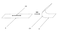
- the bending direction refers to a direction orthogonal to the folding portion (reference numeral 21) assumed in the application of the foldable display, as shown by reference numeral 22 on the polyester film (reference numeral 2) of FIG.
- the refractive index in at least one of the longitudinal direction and the width direction is 1.590 to 1.620, there is little deformation when repeatedly folded, and there is no risk of deteriorating the image quality of the foldable display, which is preferable.
- the refractive index is more preferably 1.591 to 1.600.
- the direction is preferably the above-mentioned bending direction. If it is 1.590 or more, there is no possibility that cracks will occur in the folding portion direction after the bending test described later, and of course, breakage will not occur, so that the visibility of the display can be kept good.
- the refractive index of the polyester film can be effectively adjusted by adjusting the stretching ratio and the stretching temperature. Further, a relaxation step in the stretching direction and multi-step stretching may be used to adjust the refractive index. When performing multi-stage stretching, it is preferable that the stretching ratio of the second and subsequent stages is higher than the stretching ratio of the first stage.
- the refractive index in at least one of the longitudinal direction (mechanical flow direction) and the width direction of the polyester film in the above range more preferably by controlling the refractive index in the bending direction in the above range, at the time of folding. Fatigue due to compressive stress applied to the inside of the fold can be reduced. Fatigue due to compressive stress is thought to occur mainly in the crystal part, and the smaller the number of crystals in the bending direction, the less fatigue. Therefore, it is considered that by lowering the refractive index, the amount of oriented crystals in the bending direction is reduced and compression fatigue is suppressed.
- the creep phenomenon caused by the tensile stress applied to the outside of the folding at the time of folding can be suppressed by reducing the refractive index.
- Fatigue due to tensile stress is thought to occur mainly in the amorphous part, and the molecular chains are aligned and deformed due to repeated stress. It can be inferred that the smaller the number of molecular chains aligned in the bending direction, the smaller the deformation due to alignment.
- the crystallinity that is, the density is preferable.
- the unstretched polyester sheet preferably has a draw ratio of 1.2 to 2.0 times in at least one of the longitudinal direction (mechanical flow direction) and the width direction, 1.7 to 2. 0 times is more preferable.
- the stretching direction is preferably the bending direction.
- a draw ratio of 1.2 times or more is preferable because there is no deformation in post-processing such as during hard coat coating, and a draw ratio of 2.0 times or less is preferable because uneven film thickness does not occur.
- the stretching temperature is preferably 75 to 120 ° C., more preferably 75 to 105 ° C.
- conventionally known means such as a hot air heating method, a roll heating method, and an infrared heating method can be adopted.
- the stretching temperature By setting the stretching temperature to 75 to 120 ° C., it is possible to prevent large thickness unevenness due to stretching at the above stretching ratio.
- the refractive index in the thickness direction can be reduced by stretching at a low temperature as much as possible within a range that does not cause large thickness unevenness as described above.
- the refractive index of the polyester film in the direction orthogonal to the direction in which the refractive index is 1.590 to 1.620 is preferably 1.670 to 1.700. That is, it is preferable that the refractive index in the direction orthogonal to the bending direction (direction of the folded portion) is 1.670 to 1.700.
- the refractive index in the direction orthogonal to the bending direction is 1.670 to 1.700.
- Examples of the method for adjusting the refractive index in the direction orthogonal to the bending direction include stretching ratio, stretching preheating temperature, stretching temperature, multi-stage stretching, and film relaxation.
- the draw ratio is preferably 4.0 to 6.0 times, more preferably 4.4 to 6.0 times.
- the stretching preheating temperature in the direction orthogonal to the bending direction is preferably 70 to 110 ° C.
- the film may be relaxed by 1 to 10% in either the machine flow direction (longitudinal direction) or the vertical direction (width direction).
- the refractive index in the thickness direction is preferably 1.520 or less. By setting it to 1.520 or less, even if the refractive index in the bending direction is designed to be low, it is possible to suppress a decrease in the hardness of the film surface, and it is possible to achieve both flexibility and surface hardness. .. By setting it to 1.520 or less, the pushing depth after unloading the test force in the thickness direction can be reduced, and the hardness of the film surface, particularly the pencil hardness of the hard coat film after laminating the hard coat layer can be improved. It is more preferably 1.515 or less, further preferably 1.510 or less, particularly preferably 1.505 or less, and most preferably 1.500 or less.
- the refractive index in the thickness direction is preferably low, but 1.3 or more is preferable in terms of stable production, and it may be 1.4 or more. Especially preferably, it is 1.410 or more. It can be said that the above range can be achieved by increasing the stretching ratio in both the bending direction and the folding direction, but the refractive index in the thickness direction is controlled after controlling the refractive index in the bending direction and the width direction within a preferable range. In order to do so, it is preferable to set the conditions while checking the balance of each process condition in the film forming process.
- the method of controlling the refractive index in the thickness direction within the above range is the stretching preheating temperature in the bending direction, the stretching temperature, the stretching ratio, the stretching preheating temperature in the direction of the folding portion, the stretching temperature, the multi-stage stretching, the high magnification stretching, or the heat fixing.
- the stretching preheating temperature in the bending direction is preferably 70 ° C. to 110 ° C.
- the stretching temperature in the bending direction is preferably 75 to 120 ° C.
- the draw ratio in the bending direction is preferably 1.2 to 2.0 times, more preferably 1.7 to 2.0 times.
- the stretching preheating temperature in the folding portion direction is also preferably 75 ° C. to 110 ° C.
- the stretching temperature is preferably 75 to 120 ° C.
- the draw ratio of the folded portion is preferably 4.0 to 6.0 times, more preferably 4.4 to 6.0 times.
- the refractive index in the thickness direction can be effectively reduced while maintaining or reducing the refractive index in the bending direction.
- multi-stage stretching may be used. In that case, it is preferable to make the stretching ratio of the second stage higher than the stretching ratio of the first stage because the refractive index can be effectively controlled.
- a method of stretching again after the crystallization step may be used.
- the heat fixing temperature is preferably 180 to 240 ° C.
- orientation crystallization in the stretching direction proceeds, and the refractive index in the thickness direction can be lowered.
- aromatics such as benzene rings in the molecular chain are oriented in the plane direction to suppress deformation due to stress applied in the thickness direction. It is thought that it has the effect of
- the density of the polyester film is preferably 1.380 g / cm 3 or more. More preferably, it is 1.383 g / cm 3 or more. By setting it to 1.380 g / cm 3 or more, the flexibility can be improved, and the film surface hardness, particularly the pencil hardness of the hard coat film after laminating the hard coat layer can be improved. The higher the density, the more preferable it is, and although it depends to some extent depending on the presence or absence of particles in the film, it is preferably 1.40 g / cm 3 or less. By setting the heat fixing temperature at the time of film formation to 180 to 240 ° C., crystallization can proceed and the density can be effectively increased.
- the bending direction of the polyester film corresponds to the longitudinal direction (machine flow direction). By doing so, it is easy to lower the refractive index in the bending direction at the biaxial stretching and improve the flexibility. That is, it is preferable to stretch the unstretched polyester sheet at a stretching ratio of 1.2 to 2.0 times, more preferably 1.7 to 2.0 times in the longitudinal direction to obtain a polyester film. Then, in the width direction, it can be said that it is preferable to stretch at a stretching ratio of 4.0 to 6.0 times, more preferably 4.4 to 6.0 times.
- the polyester film has (1) a refractive index in the bending direction of 1.590 to 1.620.
- the refractive index in the direction of the folding part is 1.670 to 1.700.
- the refractive index in the thickness direction is 1.520 or less and (4) the density is 1.380 g / cm 3 or more at the same time, but it is within the above-mentioned preferable production conditions.
- the stretching ratio in the bending direction is 1.4 times or less
- the stretching ratio in the folding portion direction is less than 4.4 times
- the heat fixing temperature is 220 ° C. or less.
- the stretching ratio in the bending direction may be increased to 1.7 times or more
- the stretching ratio in the direction of the folding portion may be increased to 4.4 times or more
- the heat fixing temperature may be increased to about 230 ° C.
- the above four characteristics can be satisfied at the same time by fine-tuning any of the conditions or a combination thereof, such as lowering the stretching temperature in the bending direction and / or the folding portion direction.
- any film-forming method such as stretching, relaxation, heat fixation, and surface treatment may be used, but the refractive index and density of the film are described above. It can be said that it is a particularly preferable aspect in the present invention to control the above in a preferable range.
- it is suitable for foldable displays, which can obtain better bending resistance and surface hardness than conventional films, especially high pencil hardness of hard coat film after laminating a hard coat layer.
- Polyester film can be provided.
- PET pellets are sufficiently vacuum-dried, then supplied to an extruder, melt-extruded into a sheet at about 280 ° C., cooled and solidified to form an unstretched PET sheet.
- the obtained unstretched sheet is stretched 1.2 to 2.0 times, more preferably 1.7 to 2.0 times in the longitudinal direction with a roll heated to 75 to 120 ° C. to obtain a uniaxially oriented PET film. ..
- the edge of the film is gripped with a clip and guided to a hot air zone heated to 75 to 120 ° C., and after drying, 4.0 to 6.0 times in the width direction, more preferably 4.4 to 6. Stretch 0 times.
- the heat treatment zone of 180 to 240 ° C. can be guided to perform the heat treatment for 1 to 60 seconds. In this heat treatment step, if necessary, a relaxation treatment of 0 to 10% may be performed in the width direction or the longitudinal direction.
- the ultimate viscosity of the polyester film is preferably in the range of 0.50 to 1.0 dl / g.
- the ultimate viscosity is 0.50 dl / g or more, the impact resistance is improved and the internal circuit of the display is less likely to be disconnected due to an external impact, which is preferable.
- the ultimate viscosity is 1.00 dl / g or less, the film production is stable and preferable without the increase in the filter pressure of the molten fluid becoming too large.
- the easy-adhesion layer in order to improve the adhesiveness between the polyester film and the transparent conductive layer or the hard coat layer, it is also preferable to laminate the easy-adhesion layer on the polyester film.
- a coating liquid for forming the easy-adhesive layer is applied to one or both sides of an unstretched or longitudinally uniaxially stretched film, heat-treated and dried as necessary, and further unstretched in at least one direction. It can be obtained by stretching to. Heat treatment can be performed even after biaxial stretching.
- the final coating amount of the easy-adhesion layer is preferably controlled to 0.005 to 0.20 g / m 2 . When the coating amount is 0.005 g / m 2 or more, adhesiveness is obtained, which is preferable. On the other hand, when the coating amount is 0.20 g / m 2 or less, blocking resistance is obtained, which is preferable.
- the resin contained in the coating liquid used for laminating the easy-adhesion layer for example, polyester resin, polyether polyurethane resin, polyester polyurethane resin, polycarbonate polyurethane resin, acrylic resin and the like can be used without particular limitation.
- the cross-linking agent contained in the coating liquid for forming an easy-adhesion layer include melamine compounds, isocyanate compounds, oxazoline compounds, epoxy compounds, and carbodiimide compounds. It is also possible to use a mixture of two or more of each. Due to the nature of the in-line coating, these are preferably coated with an aqueous coating liquid, and the resin or cross-linking agent is preferably a water-soluble or water-dispersible resin or compound.
- the average particle size of the fine particles is preferably 2 ⁇ m or less. When the average particle size of the particles exceeds 2 ⁇ m, the particles are likely to fall off from the easy-adhesion layer.
- the particles contained in the easy-adhesion layer include titanium oxide, barium sulfate, calcium carbonate, calcium sulfate, silica, alumina, talc, kaolin, clay, calcium phosphate, mica, hectrite, zirconia, tungsten oxide, and lithium fluoride.
- examples thereof include inorganic particles such as calcium fluoride and organic polymer particles such as styrene-based, acrylic-based, melamine-based, benzoguanamine-based, and silicone-based particles. These may be added to the easy-adhesion layer alone, or may be added in combination of two or more.
- a known method can be used in the same manner as the above-mentioned coating layer.
- the reverse roll coating method, the gravure coating method, the kiss coating method, the roll brush method, the spray coating method, the air knife coating method, the wire bar coating method, the pipe doctor method, etc. can be mentioned, and these methods can be used alone. Alternatively, it can be performed in combination.
- the polyester film is applied to at least one surface of the polyester film in order to adjust the refractive index, improve the surface hardness, improve the bending resistance, crack / break, and block the adverse effect of the oligomer precipitated from the polyester on the transparent conductive layer. It is preferable to have a hard coat layer.
- the hard coat layer is preferably used by being positioned on the polyester film or on the easy-adhesion layer.
- acrylic type, siloxane type, inorganic hybrid type, urethane acrylate type, polyester acrylate type, epoxy type and the like can be used without particular limitation. Further, two or more kinds of materials can be mixed and used, and particles such as an inorganic filler and an organic filler can be added.
- the film thickness of the hard coat layer is preferably 1 to 50 ⁇ m. When it is 1 ⁇ m or more, it is sufficiently cured and the pencil hardness becomes high, which is preferable. Further, by setting the thickness to 50 ⁇ m or less, curling due to curing shrinkage of the hard coat can be suppressed, and the handleability of the film can be improved.
- a Meyer bar, a gravure coater, a die coater, a knife coater and the like can be used without particular limitation, and can be appropriately selected according to the viscosity and the film thickness.
- a curing method of the hard coat layer energy rays such as ultraviolet rays and electron beams and a curing method by heat can be used, and in order to reduce damage to the film, a curing method using ultraviolet rays and electron beams is preferable.
- the pencil hardness of the hard coat layer is preferably 3H or higher, and more preferably 4H or higher. If the pencil has a hardness of 3H or more, the surface is protected, scratches and dents are not easily formed, and visibility is not deteriorated. Generally, it is preferable that the pencil hardness of the hard coat layer is high, but it may be 9H or less, 8H or less, or 6H or less without any problem in practical use.
- the hard coat layer in the present invention can be used for the purpose of increasing the pencil hardness of the surface as described above to protect the touch panel module and the display, and preferably has a high transmittance.
- the transmittance of the hard coat film is preferably 87% or more, more preferably 88% or more. When the transmittance is 87% or more, sufficient visibility can be obtained.
- the higher the total light transmittance of the hard coat film, the more preferable, but from the viewpoint of stable production it is preferably 99% or less, and may be 97% or less.
- the haze of the hard coat film is generally preferably low, preferably 3% or less.
- the haze of the hard coat film is more preferably 2% or less, and most preferably 1% or less.
- the visibility of the image can be improved.
- 0.1% or more is preferable, and 0.3% or more may be used.
- the hard coat layer may have other functions added to it.
- the present invention also includes a hard coat layer having functionality such as an antiglare layer having a certain pencil hardness, an antiglare antireflection layer, an antireflection layer, a low reflection layer, and an antistatic layer as described above. Is preferably applied.
- the hard coat layer itself may also serve as the refractive index adjusting layer, and the refractive index adjusting may be separately laminated.
- the refractive index adjusting layer include the above-mentioned resin layer containing the refractive index adjusting particles, a fluorine-containing resin layer, an aromatic polyimide resin, an epoxy resin, a (meth) acrylic resin (acrylate, a methacrylate compound), a polyester resin, and a urethane resin.
- the resin material examples include an aromatic ring, a resin having a high refractive index containing a sulfur atom or a bromine atom, and a layer such as a precursor thereof, which can be provided by coating.
- a layer such as a precursor thereof, which can be provided by coating.
- the refractive index adjusting layer ZnO, CeO 2 , Sb 2 O 3 , SnO 2 , indium tin oxide, In 2 O 3 , Al 2 O 3 , antimony-doped tin oxide, aluminum-doped zinc oxide, SiO 2 , and fluoride.
- Inorganic layers such as magnesium are also preferable, and these can be provided by a wet film forming method.
- the preferred laminated structure thereof is, for example, polyester film / transparent conductive layer, polyester film / easy-adhesion layer / transparent conductive layer, polyester film / Hard coat layer / transparent conductive layer, polyester film / easy adhesive layer / hard coat layer / transparent conductive layer, polyester film / refractive index adjustment layer (one layer or multiple layers with different refractive coefficients) / transparent conductive layer, polyester film / easy Adhesive layer / refractive index adjusting layer (one layer or multiple layers with different refractive coefficients) / transparent conductive layer, polyester film / hard coat layer / refractive index adjusting layer (one layer or multiple layers with different refractive coefficients) / transparent conductive layer, Examples include a polyester film / easy-adhesion layer / hard coat layer / refractive index adjusting layer (one layer or multiple layers having different refractive indices) / transparent conductive layer, etc.
- the polyester film of the present invention is used as the base material constituting the touch panel module, but it is not necessary to be used for all the films constituting the touch panel module.
- a polyimide film, a polyamide film, a polyamideimide film, a polyester film other than the polyester film of the present invention in addition to the polyester film of the present invention, a polyimide film, a polyamide film, a polyamideimide film, a polyester film other than the polyester film of the present invention, a polycarbonate film, an acrylic film, a triacetyl cellulose film, and a cycloolefin It can be used as a base film for a touch panel module, such as a polymer film, a polyphenylene sulfide film, or a polymethylpentene film, as appropriate.
- FIG. 1 is a schematic view for showing the bending radius when the foldable display is folded, and in consideration of the case where the polyester film is arranged on the inner surface of the folded form, FIG.
- the bending test is performed as a model assuming that the location of reference numeral 11 is set to 1.5 mm. After the bending treatment was completed, the sample was placed on a flat surface with the inside of the bending facing down, and visually observed. ⁇ : No cracks or deformation can be confirmed in the sample. ⁇ : The sample has cracks or creases, and when placed horizontally, the maximum height is 5 mm or more.
- FIG. 1 is a schematic view for showing the bending radius when the foldable display is folded, and in consideration of the case where the polyester film is arranged on the inner surface of the folded form, FIG.
- the bending test is performed as a model assuming that the location of reference numeral 11 is set to 0.5 mm.
- the film surface on the outside of the bent portion was observed at 700 times that of a digital microscope (RH8800 manufactured by HIROX), and the presence or absence of wrinkles (cracks) was observed.
- FIG. 1 is a schematic view for showing the bending radius when the foldable display is folded, and in consideration of the case where the polyester film is arranged on the inner surface of the folded form, FIG. The bending test is performed as a model assuming that the location of reference numeral 11 is set to 1.5 mm.
- the sample was placed on a flat surface with the inside of the bending facing down, and visually observed.
- ⁇ No cracks or deformation (distortion) can be confirmed in the sample.
- ⁇ The sample has cracks or creases, and when placed horizontally, the maximum height is 5 mm or more.
- Refractive index In accordance with JIS K 7142: 2014 "Method for measuring the refractive index of plastics (Method A)", an Abbe refractive index meter (manufactured by Atago, NAR-4T, measurement wavelength 589 nm) is used in the longitudinal direction. The refractive index, the refractive index in the width direction, and the refractive index in the thickness direction were determined.
- Pencil hardness Using the pencil hardness of the hard coat film as a sample, the measurement was performed at a load of 750 g and a speed of 1.0 mm / s according to JIS K 5600-5-4: 1999. In the present invention, 3H or more was regarded as acceptable.
- Total light transmittance was measured using a haze haze meter (NDH5000, manufactured by Nippon Denshoku Kogyo Co., Ltd.).
- Density The density was measured according to a method (density gradient tube method) conforming to JIS K 7112: 1999. (Unit: g / cm 3 ).
- Test force Pushing depth after unloading The sample is cut into a square of about 2 cm, and the opposite side of the measurement surface is glued (Cemedine (registered trademark) high) on the micro cover glass 18 x 18 mm (manufactured by Matsunami Glass Co., Ltd.). It was fixed at Super 30). After sticking and fixing, leave it at room temperature for 12 hours or more, and then use a dynamic ultra-micro hardness tester "DUH-211" (manufactured by Shimadzu Corporation) under the following conditions to push in depth after unloading the test force ( ⁇ m) was measured.
- a dynamic ultra-micro hardness tester "DUH-211" manufactured by Shimadzu Corporation
- Test mode Load-unload test Indenter used: Ridge angle 115 degrees, triangular pyramid indenter Indenter modulus: 1.140 ⁇ 10 6 N / mm 2 Indenter Poisson's ratio: 0.07 Test power: 50mN Load speed: 4.44 mN / sec Load holding time: 2 sec Unloading retention time: 0 sec
- Heat shrinkage rate (%) [(AB) x 100] / A
- the sample film is cut and measured separately in both the bending direction and the folding direction so that the vertical and horizontal directions are different, and the data in the direction in which the measured value is large is defined as the maximum heat shrinkage rate (%).
- esterification reaction device a continuous esterification reaction device consisting of a three-stage complete mixing tank having a stirrer, a splitter, a raw material charging port and a product extraction port is used, the TPA is 2 tons / hr, and the EG is TPA1.
- the amount of antimony trioxide is 2 mol per mol
- the amount of Sb atom is 160 ppm with respect to the produced PET, and these slurries are continuously supplied to the first esterification reaction can of the esterification reaction apparatus at normal pressure.
- the reaction was carried out at 255 ° C. with an average residence time of 4 hours.
- the reaction product in the first esterification reaction can is continuously taken out of the system and supplied to the second esterification reaction can, and distilled from the first esterification reaction can in the second esterification reaction can.
- 8% by mass of the EG to be produced is supplied to the produced polymer (produced PET), and an EG solution containing magnesium acetate in an amount of 65 ppm of Mg atoms with respect to the produced PET and 20 ppm of P atoms with respect to the produced PET.
- An EG solution containing an amount of TMPA was added, and the reaction was carried out at normal pressure at an average residence time of 1.5 hours and at 260 ° C.
- the reaction product in the second esterification reaction can is continuously taken out of the system and supplied to the third esterification reaction can, and further contains TMPA in an amount of 20 ppm of P atoms with respect to the produced PET.
- An EG solution was added, and the reaction was carried out at normal pressure at an average residence time of 0.5 hours and at 260 ° C.
- the esterification reaction product produced in the third esterification reaction can is continuously supplied to a three-stage continuous polycondensation reaction apparatus to perform polycondensation, and further, a filter medium of a stainless sintered body (nominal filtration accuracy of 5 ⁇ m). The particles were filtered through 90% of the particles) to obtain polyethylene terephthalate pellets (a) having an ultimate viscosity of 0.62 dl / g.
- reaction solution reached a predetermined amine equivalent.
- reaction solution was cooled to 40 ° C., and then 9.03 parts by mass of triethylamine was added to obtain a polyurethane prepolymer D solution.
- 450 g of water was added to a reaction vessel equipped with a homodisper capable of high-speed stirring, adjusted to 25 ° C., and while stirring and mixing at 2000 min-1, the isocyanate group-terminated prepolymer was added and water dispersed. did. Then, under reduced pressure, acetonitrile and a part of water were removed to prepare a water-soluble polyurethane resin (A) having a solid content of 35% by mass.
- Example 1 The polyethylene terephthalate pellet (a) was supplied to the extruder and melted at 285 ° C. This polymer is filtered through a stainless sintered filter medium (nominal filtration accuracy of 10 ⁇ m particles 95% cut), extruded into a sheet from the base, and then cast into a casting drum with a surface temperature of 30 ° C. using an electrostatic application casting method. They were brought into contact and cooled and solidified to form an unstretched film. This unstretched film was uniformly heated to 75 ° C. using a heating roll and heated to 85 ° C. with a non-contact heater to perform 1.4 times roll stretching (longitudinal stretching).
- the above-mentioned coating liquid for forming an easy-adhesive layer was applied to both sides of the obtained uniaxially stretched film by a roll coating method, and then dried at 80 ° C. for 20 seconds.
- the final (after biaxial stretching) coating amount after drying was adjusted to 0.06 g / m 2 . Then, it is guided to a tenter, preheated at 105 ° C., laterally stretched 4.0 times at 95 ° C., fixed in width, heat-fixed at 230 ° C. for 5 seconds, and further relaxed by 4% in the width direction at 180 ° C.
- a polyethylene terephthalate film having a thickness of 50 ⁇ m was obtained.
- Example 2 A polyester film was obtained in the same manner as in Example 1 except that the stretching ratio in the longitudinal direction shown in Table 1 was changed.
- Example 4 A polyester film was obtained in the same manner as in Example 1 except that the stretching ratio in the width direction was changed to 4.4 times and the heat fixing temperature was changed to 220 ° C.
- Example 5 A polyester film was obtained in the same manner as in Example 4 except that the stretching ratio was changed in the longitudinal direction as shown in Table 1.
- Example 7 A polyester film was obtained in the same manner as in Example 1 except that the stretching ratio in the width direction was changed to 5.5 times and the heat fixing temperature was changed to 190 ° C.
- Example 8 A polyester film was obtained in the same manner as in Example 7 except that the stretching ratio was changed in the longitudinal direction as shown in Table 1.
- Example 10 In the production process of Example 5, a polyester film was obtained in the same manner as in Example 5 except that the film was stretched in the longitudinal direction and then subjected to a relaxation heat treatment of 10% at 100 ° C.
- Example 11 In the manufacturing process of Example 5, a polyester film was obtained in the same manner as in Example 5 except that the clip was opened at 200 ° C. after heat fixing and relaxation heat treatment was performed in the longitudinal direction and the width direction. In the longitudinal direction, the tenter speed and the take-up roll speed were adjusted so that the relaxation rate was 3%. Relaxation in the width direction was left free.
- Example 12 A polyester film was obtained in the same manner as in Example 1 except that the temperature at the time of stretching in the longitudinal direction was changed to 75 ° C. and the heat fixing temperature was changed to 220 ° C.
- Example 13 The temperature at the time of stretching in the longitudinal direction was changed to 75 ° C., the stretching ratio was changed to 1.2 times, and then the stretching ratio was changed to 5.0 times in the width direction, and the stretching was performed in the same manner as in Example 1. Obtained a polyester film.
- Example 14 The stretching in the longitudinal direction of Example 3 was set to two-step stretching, the stretching ratio of the first step was set to 1.2 times, and the stretching ratio of the second step was set to 1.67 times in the same manner as in Example 3. A polyester film was obtained. The total elongation ratio in the longitudinal direction is about 2.0 times.
- Example 15 A polyester film was obtained in the same manner as in Example 5 except that the preheating temperature at the time of stretching in the width direction was changed to 95 ° C. and the heat fixing temperature was changed to 190 ° C.
- Example 16 The stretching in the width direction of Example 2 was defined as two-stage stretching, the first-stage stretching ratio was 1.5 times, the second-stage stretching ratio was 4.0 times, and the heat fixing temperature was changed to 190 ° C.
- a polyester film was obtained in the same manner as in Example 2.
- the total draw ratio in the width direction is 6.0 times.
- Example 17 to 18 A polyester film was obtained in the same manner as in Example 2 except that the thickness was changed as shown in Table 1.
- Example 19 A polyester film was obtained in the same manner as in Example 1 except that the relaxation heat treatment in the width direction was not performed in the manufacturing process of Example 1.
- Example 20 After preparing an unstretched film in the same manner as in Example 1, the unstretched film was preheated at 75 ° C. with a tenter and laterally stretched 1.4 times at 85 ° C. The above-mentioned coating liquid for forming an easy-adhesion layer was applied to both sides of the obtained uniaxially stretched film by a roll coating method, and then dried at 80 ° C. for 20 seconds. The final (after biaxial stretching) coating amount after drying was adjusted to 0.06 g / m 2 . Uniformly heat to 105 ° C. using a heating roll and heat to 95 ° C. with a non-contact heater. Roll stretching (longitudinal stretching) was performed 4.0 times. The width was fixed and heat-fixed at 230 ° C. for 5 seconds to obtain a polyethylene terephthalate film having a thickness of 50 ⁇ m.
- Example 21 A polyethylene terephthalate film having a thickness of 50 ⁇ m was obtained in the same manner as in Example 1, and then a hard coat film coated with the hard coat coating liquid b was obtained.
- Example 1 A polyester film was obtained in the same manner as in Example 1 except that the film was stretched only in the width direction without stretching in the longitudinal direction to obtain a lateral uniaxial stretching.
- Example 2 A polyester film was obtained in the same manner as in Example 7 except that the film was stretched only in the width direction without stretching in the longitudinal direction and was stretched in the lateral uniaxial direction.
- Comparative Examples 3 to 7 A polyester film was obtained in the same manner as in Example 1 except that the heat fixing temperature was changed to 220 ° C. and the PET pellets and thicknesses shown in Table 1 were used. Comparative Examples 3 to 7 are a combination of each condition level which is not the best in the condition range in which the heat fixing temperature is lower than that of Example 1 and the stretching ratio in the longitudinal direction and the width direction is preferable as described above. As described in No. 1, the refractive index in the thickness direction increased, the pushing depth after unloading the test force was large, and the pencil hardness after laminating the hard coat layer was smaller than in each example.
- Example 8 A polyester film was obtained in the same manner as in Example 1 except that the stretching ratio in the longitudinal direction was changed to 2.7 times and the heat fixing temperature was changed to 220 ° C.
- Example 9 A polyester film was obtained in the same manner as in Example 1 except that the stretching ratio in the longitudinal direction was changed to 3.4 times.
- Example 12 A polyester film was obtained in the same manner as in Example 1 except that the preheating temperature in the width direction was changed to 120 ° C.
- a hard coat coating liquid a is applied to one surface of the above-mentioned film so that the film thickness after drying is 5 ⁇ m, dried at 80 ° C. for 1 minute, and then irradiated with ultraviolet rays. (Integrated light amount 200 mJ / cm 2 ), a hard coat film was obtained. Then, using a Meyer bar, a metal nanowire-containing coating liquid was applied to the surface of the prepared hard coat layer so that the film thickness after drying was 5 ⁇ m, dried at 80 ° C. for 10 minutes, and then transparent conductivity. A polyester film was obtained. The evaluation results are shown in Table 1.
- the transparent conductive polyester film produced above was incorporated into the touch panel module to create a smartphone-type foldable display that can be folded in half at the center of the entire center where the radius corresponding to the bending radius in FIG. 1 is 3 mm.
- the one using the touch panel module containing the transparent conductive polyester film made of the polyester film of each embodiment was satisfied with the operation and visibility as a smartphone that can be folded in half at the center and carried.
- the surface was not dented by an external force.
- Examples 6 to 9, 15 and 16 since the maximum heat shrinkage rate of the polyester film was slightly large, it was slightly inferior to the other examples in terms of less curl after heat processing. , Overall it was satisfactory.
- the foldable display using the polyester film or the hard coat film of each comparative example seems to have caused image distortion in the foldable part of the display as the frequency of use increases, which is not very preferable. .. In addition, some were dented on the surface and scratches were confirmed.
- the foldable display using the polyester film for the touch panel module base material of the foldable display of the present invention is deformed after the polyester film located in the touch panel module of the foldable display is repeatedly folded while maintaining mass productivity. Therefore, the image is not distorted at the folded part of the display.
- a mobile terminal device or an image display device equipped with a foldable display using the polyester film of the present invention as a touch panel module base material provides beautiful images, is rich in functionality, and is excellent in convenience such as portability. Is.
- Folding display 11 Bending radius 2: Polyester film for touch panel module of foldable display 21: Folding part 22: Bending direction (direction orthogonal to the folding part)
Abstract
Description
1. 下記条件を満足する折りたたみ型ディスプレイのタッチパネルモジュール基材用ポリエステルフィルム。
(1)屈曲方向の屈折率が1.590~1.620
(2)折りたたみ部の方向の屈折率が1.670~1.700
(3)厚み方向の屈折率が1.520以下
(4)密度が1.380g/cm3以上
(ここで、屈曲方向とは、ポリエステルフィルムを折りたたむ際の折りたたみ部と直交する方向をいう。)
2. 屈曲方向の弾性率が2.7GPa以下、折りたたみ部の方向の弾性率が4.5GPa以上である上記第1に記載の折りたたみ型ディスプレイのタッチパネルモジュール基材用ポリエステルフィルム。
3. 全光線透過率が85%以上、ヘイズが3%以下、かつ、最大熱収縮率が2%以下である上記第1または第2に記載の折りたたみ型ディスプレイのタッチパネルモジュール基材用ポリエステルフィルム。
4. 150℃、30分熱処理後の耐屈曲性評価(屈曲半径1.5mm)において、クラックや変形が確認できない上記第1~第3のいずれかに記載の折りたたみ型ディスプレイのタッチパネルモジュール基材用ポリエステルフィルム。
5. 前記折りたたみ型ディスプレイのタッチパネルモジュール基材用ポリエステルフィルムの少なくとも片面上に易接着層を有する上記第1~第4のいずれかに記載の折りたたみ型ディスプレイのタッチパネルモジュール基材用ポリエステルフィルム。
6. 前記折りたたみ型ディスプレイのタッチパネルモジュール基材用ポリエステルフィルムの少なくとも片面上に厚みが1~50μmのハードコート層を有する上記第1~第5のいずれかに記載の折りたたみ型ディスプレイのタッチパネルモジュール基材用ポリエステルフィルム。
7. 上記第1~第6のいずれかに記載の折りたたみ型ディスプレイのタッチパネルモジュール基材用ポリエステルフィルムが、タッチパネルモジュールの基材フィルムとして含まれた折りたたみ型ディスプレイであって、折りたたみ型ディスプレイの折りたたみ部を介して連続した単一のタッチパネルモジュールの基材フィルムが含まれている折りたたみ型ディスプレイ。
8. 上記第7に記載の折りたたみ型ディスプレイを有する携帯端末機器。
ルムを用いた折りたたみ型ディスプレイは、量産性を維持しながら、そのポリエステルフィルムが、折りたたみ部にクラックが発生することがなく、繰り返し折りたたんだ後の変形を起こさず、ディスプレイの折りたたみ部分での画像の乱れを生じないものである。前記のようなポリエステルフィルムをタッチパネルモジュール基材用途として用いた折りたたみ型ディスプレイを搭載した携帯端末機器は、美しい画像を提供し、機能性に富み、携帯性等の利便性に優れたものである。
本発明で言うディスプレイとは、表示装置を全般に指すものであり、ディスプレイの種類としては、LCD、有機ELディスプレイ、無機ELディスプレイ、LED、FEDなどあるが、折曲げ可能な構造を有するLCDや、有機EL、無機ELが好ましい。特に層構成を少なくすることができる有機EL、無機ELが特に好ましく、色域の広い有機ELがさらに好ましい。
折りたたみ型ディスプレイは、連続した1枚のディスプレイが、携帯時は2つ折りなどに折りたたむことができるものである。折りたたむことでサイズを半減させ、携帯性を向上させることができる。折りたたみ型ディスプレイの屈曲半径は5mm以下が好ましく、3mm以下がさらに好ましい。屈曲半径が5mm以下であれば、折りたたんだ状態での薄型化が可能となる。屈曲半径は小さいほど良いと言えるが、屈曲半径が小さいほど折り跡がつきやすくなる。屈曲半径は0.1mm以上が好ましいが、0.5mm以上であってもよく、1mm以上であってもよい。屈曲半径が1mmであっても、携帯時には実用的に十分な薄型化を達成することができる。折りたたんだ際の屈曲半径とは、図1の模式図の符号11の箇所を測定するもので、折りたたんだ際の折りたたみ部分の内側の半径を意味している。なお、後述する表面保護フィルムは、折りたたみ型ディスプレイの折りたたんだ外側に位置していてもよいし、内側に位置していてもよい。
また、折りたたみ型ディスプレイは3つ折り、4つ折りであってもよく、さらに、ローラブルといわれる巻き取り型であってもよく、これらいずれも本発明でいう折りたたみ型ディスプレイの範囲に入るものとする。
折りたたみ型有機ELディスプレイの必須構成としては、有機ELモジュールであるが、さらに必要に応じて、円偏光板、タッチパネルモジュール、表面保護フィルム、裏面保護フィルムなどが設けられる。
携帯端末機器はタッチパネルを有することが好ましい。有機ELディスプレイを用いた
場合、有機ELモジュールの視認側に配置されていることが好ましく、さらには、有機ELモジュール/円偏光板間にタッチパネルモジュールが配置されていることが好ましい。タッチパネルモジュールはフィルムなどの透明基材とその上に配置された透明導電層を有する透明導電性フィルムを有することが好ましい。本発明におけるポリエステルフィルムはこの透明導電性フィルムの透明基材として用いられることができる。透明導電性フィルムの透明基材として用いる場合、ポリエステルフィルムには屈折率調整層やハードコート層を設けることが好ましい。
本発明においてタッチパネルモジュールに好ましく含まれる導電層は透明であり、かつ導電性を有する層であればよく、特に限定されないが、導電性フィラー含有層、金属層、金属酸化物層、さらに導電性ポリマー含有層等が挙げられる。
導電性ポリマー含有層は、塗工法により設けることができ、電極パターンは導電性フィラー含有層での説明と同様の方法で設けることができる。
この場合、基材には加熱処理後でも屈曲時での表面クラック、変形、割れがない、高い耐屈曲性が必要される。本発明のタッチパネルモジュール基材用ポリエステルフィルムでは、加熱処理後の耐屈曲性を失う、または悪化させることなく、高い耐屈曲性を維持することができる。
なお、本発明のタッチパネルモジュール用の基材フィルムを単に基材フィルム、ポリエステルフィルムと称することがある。
、グリコール成分としては、例えば、エチレングリコール、ジエチレングリコール、1,4-ブタンジオール、プロピレングリコール、ネオペンチルグリコールなどの脂肪酸グリコール;p-キシレングリコールなどの芳香族グリコール;1,4-シクロヘキサンジメタノールなどの脂環族グリコール;平均分子量が150~20,000のポリエチレングリコールが挙げられる。好ましい共重合体の共重合成分の質量比率は20質量%未満である。20質量%未満の場合には、フィルム強度、透明性、耐熱性が保持されて好ましい。
GPa以上であることがより好ましく、4.7GPa以上であることが更に好ましい。折りたたみ方向の弾性率を高くすることで、ディスプレイ作成時にディスプレイ表面の平面性を保つことができる。また、外部の衝撃からタッチパネルモジュールを保護することができる。折りたたみ方向の弾性率は高い程好ましいが、製膜性の観点から8.0GPa以下が好ましい。
本発明において、ポリエステルフィルムの長手方向(機械流れ方向)及び幅方向の少なくともいずれか一方向の屈折率は1.590~1.620であることが好ましく、更に好ましくは、1.591~1.600である。そして、ポリエステルフィルムの屈曲方向の屈折率が1.590~1.620であることが好ましく、1.591~1.600であることがより好ましい。ここで、屈曲方向とは、図2のポリエステルフィルム(符号2)上の符号22に示すように、折りたたみ型ディスプレイの用途において想定される折りたたみ部(符号21)と直交する方向を指している。長手方向及び幅方向の少なくともいずれか一方向の屈折率が1.590~1.620であると、繰り返し折りたたんだ際の変形が少なく、折りたたみ型ディスプレイの画質を低下させるおそれがなく好ましい。屈折率は1.591~1.600であることがより好ましい。もちろん、その方向は前記の屈曲方向であることが好ましい。1.590以上であると後述の屈曲試験後に折りたたみ部方向にクラックが入るおそれがなく、もちろん破断も起こらないため、ディスプレイの視認性を良好に保つことができる。ポリエステルフィルムの屈折率は、延伸倍率、延伸温度を調節することで効果的に調節することができる。また、屈折率の調整のために延伸方向の緩和工程、多段延伸を用いても良い。多段延伸を行う場合には、1段目の延伸倍率よりも2段目以降の延伸倍率を高くすることが好ましい。
上記のポリエステルフィルムの屈折率が1.590~1.620である方向と直交する方向の屈折率は、1.670~1.700であることが好ましい。即ち、屈曲方向と直交する方向(折りたたみ部の方向)の屈折率が1.670~1.700であることが好ましい。1.670~1.700にすることで屈曲方向に折りたたんだ際の変形を少なくすることができる。1.700以下にすることで折りたたみ部の方向にクラックが入ったり、
破断することを抑制することができる。1.670以上にすることで屈曲方向の屈曲性を向上させること、表面硬度を向上させることができる。1.680~1.695がより好ましい。屈曲方向と直交する方向の屈折率を調整する方法として、延伸倍率、延伸予熱温度、延伸温度、多段延伸、フィルム弛緩が挙げられる。延伸倍率は4.0~6.0倍であることが好ましく、より好ましくは、4.4~6.0である。また、屈曲方向と直交する方向の延伸予熱温度は70~110℃であることが好ましい。屈曲方向と直交する方向に多段延伸する場合、1段目より2段目以降の延伸倍率を高くする方が好ましい。フィルム弛緩は機械流れ方向(長手方向)、垂直方向(幅方向)に何れにおいても1~10%行っても良い。
厚み方向の屈折率は1.520以下であることが好ましい。1.520以下にすることで、屈曲方向の屈折率を低く設計しても、フィルム表面の硬度の低下を抑制することができ、屈曲性と表面硬度の両立を実現することができるためである。1.520以下にすることで厚み方向の試験力除荷後の押し込み深さが低減し、フィルム表面の硬度、特にハードコート層積層後のハードコートフィルムの鉛筆硬度を向上することができる。より好ましくは1.515以下、更に好ましくは1.510以下、特に好ましくは1.505以下、最も好ましくは1.500以下である。厚み方向の屈折率は低いことが好ましいが、安定した生産の面で1.3以上が好ましく、さらには1.4以上であってもよい。特に好ましくは1.410以上である。上記範囲は屈曲方向と折りたたみ方向に延伸倍率を両方に増加させていくことで達成できると言えるが、屈曲方向と幅方向の屈折率を好ましい範囲に制御した上で、厚み方向の屈折率を制御するためには、製膜工程の各工程条件のバランスを確認しながら条件設定することが好ましい。
熱固定温度は180~240℃が好ましい。熱固定を行うことで延伸方向への配向結晶化が進み、厚み方向の屈折率を下げることができる。
厚み方向の屈折率を下げることでフィルム表面の硬度が向上する理由は必ずしも明確ではないが、分子鎖内のベンゼン環等の芳香族が面方向に配向し、厚み方向にかかる応力による変形を抑制する効果があると考えられる。
ポリエステルフィルムの密度は1.380g/cm3以上であることが好ましい。1.383g/cm3以上であることがより好ましい。1.380g/cm3以上にすることで屈曲性を向上させること、フィルム表面硬度、特に、ハードコート層を積層した後のハードコートフィルムの鉛筆硬度を向上させることができる。密度は高いほど好ましく、フィルム中の粒子の有無等によっても多少左右されるが、1.40g/cm3以下であることが好ましい。製膜時の熱固定温度を180~240℃に設定することで結晶化を進行させ密度を効果的に増大させることができる。
(1)屈曲方向の屈折率が1.590~1.620
(2)折りたたみ部の方向の屈折率が1.670~1.700
(3)厚み方向の屈折率が1.520以下
(4)密度が1.380g/cm3以上
の4つの特性を同時に具備させることが特に好ましい態様と言えるが、上述の好ましい製造条件の範囲内での組合せであっても、例えば、屈曲方向の延伸倍率が1.4倍以下、折りたたみ部の方向の延伸倍率が4.4倍未満であり、かつ、熱固定温度が220℃以下の組合せであるような、各々の好ましい製造条件範囲の中において最善とは言えない条件の組合せの場合、必ずしも上記の4つの特性を同時に満足するものが得られない場合が起こり得る。この場合には、屈曲方向の延伸倍率延伸倍率を1.7倍以上に高めたり、折りたたみ部の方向の延伸倍率が4.4倍以上に高めたり、熱固定温度を230℃程度に高めたり、あるいは屈曲方向及び/又は折りたたみ部の方向の延伸温度を低くするなど、いずれかの条件の微調整またはそれらの組合せによって、上記の4つの特性を同時に満足させることができる。
本発明において、ポリエステルフィルムと透明導電層またはハードコート層などとの接着性を向上させるため、ポリエステルフィルムに易接着層を積層することも好ましい。易接着層は、易接着層形成のための塗布液を未延伸又は縦方向の1軸延伸フィルムの片面または両面に塗布した後、必要に応じて熱処理乾燥し、さらに延伸されていない少なくとも一方向に延伸して得ることができる。二軸延伸後にも熱処理することができる。最終的な易接着層の塗布量は、0.005~0.20g/m2に管理することが好ましい。塗布量が0.005g/m2以上であると、接着性が得られて好ましい。一方、塗布量が0.20g/m2以下であると、耐ブロッキング性が得られて好ましい。
ポリエステルフィルムは、屈折率の調整または表面硬度の向上、耐屈曲性、割れ・切れの向上や、ポリエステルから析出されるオリゴマーの透明導電層への悪影響の遮断等のため、その少なくとも一方の表面にハードコート層を有することが好ましい。ハードコート層は、ポリエステルフィルムの上、または易接着層の上に位置させて用いられることが好ましい。ハードコート層を形成する樹脂としては、アクリル系、シロキサン系、無機ハイブリッド系、ウレタンアクリレート系、ポリエステルアクリレート系、エポキシ系など特に限定なく使用できる。また、2種類以上の材料を混合して用いることもできるし、無機フィラーや有機フィラーなどの粒子を添加することもできる。
ハードコート層の膜厚としては、1~50μmが好ましい。1μm以上であると十分に硬化し、鉛筆硬度が高くなり好ましい。また厚みを50μm以下にすることで、ハードコートの硬化収縮によるカールを抑制し、フィルムのハンドリング性を向上させることができる。
ハードコート層の塗布方法としては、マイヤーバー、グラビアコーター、ダイコーター、ナイフコーターなど特に限定なく使用でき、粘度、膜厚に応じて適宜選択できる。
ハードコート層の硬化方法としては、紫外線、電子線などのエネルギー線や、熱による硬化方法など使用でき、フィルムへのダメージを軽減させるために、紫外線や電子線などによる硬化方法が好ましい。
ハードコート層の鉛筆硬度としては、3H以上が好ましく、4H以上が更に好ましい。3H以上の鉛筆硬度があれば、表面保護されて、容易に傷や凹みがつくことはなく、視認性も低下させない。一般にハードコート層の鉛筆硬度は高い方が好ましいが9H以下で構わず、8H以下でも構わず、6H以下でも実用上は問題なく使用できる。
本発明におけるハードコート層は、上述のような表面の鉛筆硬度を高めて、タッチパネルモジュールやディスプレイの保護をする目的に使用できるものであり、透過率が高いことが好ましい。ハードコートフィルムの透過率としては、87%以上が好ましく、88%以上がさらに好ましい。透過率が87%以上あれば、十分な視認性が得られる。ハードコートフィルムの全光線透過率は、一般的に高いほど好ましいが、安定した生産の面から99%以下が好ましく、97%以下であってもよい。また、ハードコートフィルムのヘイズは、一般的に低いことが好ましく、3%以下が好ましい。ハードコートフィルムのヘイズは2%以下がより好ましく、1%以下が最も好ましい。ヘイズが3%以下であれば、画像の視認性を向上させることができる。ヘイズは一般的には低いほどよいが、安定した生産の面から0.1%以上が好ましく、0.3%以上であってもよい。
層構造の組合せがポリエステルフィルムの片面上に存在してもよいし、ポリエステルフィルムを介して両面に存在してもよい。
フィルムまたはポリエステル樹脂を粉砕して乾燥した後、フェノール/テトラクロロエタン=60/40(質量比)の混合溶媒に溶解した。この溶液に遠心分離処理を施して無機粒子を取り除いた後に、ウベローデ粘度計を用いて、30℃で0.4(g/dl)の濃度の溶液の流下時間及び溶媒のみの流下時間を測定し、それらの時間比率から、Hugginsの式を用い、Hugginsの定数が0.38であると仮定して極限粘度を算出した。
幅方向20mm×流れ方向110mmの大きさのポリエステルフィルムサンプルを用意する。無負荷U字伸縮試験機(ユアサシステム機器社製、DLDMLH-FS)を用いて、屈曲半径1.5mmに設定し、1回/秒の速度で、20万回屈曲させた。その際、サンプルは長辺側両端部10mmの位置を固定して、屈曲する部位は20mm×90mmとした。ここで、図1は、折りたたみ型ディスプレイを折りたたんだ際の屈曲半径を示すための模式図であり、その折りたたんだ態様の内側表面にポリエステルフィルムが配されている場合を考慮して、図1の符号11の個所を1.5mmに設定したものとしてモデル的に屈曲試験をしている。屈曲処理終了後、サンプルの屈曲内側を下にして平面に置き、目視による観察を行った。
○ :サンプルにクラック及び変形を確認できない。
× :サンプルにクラックまたは折跡があり、水平に置いた際、浮き上がり最大高さが5mm以上。
上記屈曲試験と同様の方法で、屈曲半径0.5mmに設定し1回/秒の速度で20万回屈曲させた。ここで、図1は、折りたたみ型ディスプレイを折りたたんだ際の屈曲半径を示すための模式図であり、その折りたたんだ態様の内側表面にポリエステルフィルムが配されている場合を考慮して、図1の符号11の個所を0.5mmを設定したものとしてモデル的に屈曲試験をしている。屈曲部の外側のフィルム表面をデジタルマイクロスコープ(HIROX社製RH8800)の700倍で観察し、シワ(クラック)の有無を観察した。上記の屈曲半径1.5mmの耐屈曲性目視テストとは別に、屈曲半径を0.5mmに小さくした本テストを行うことで、ハードコート層や他の部材が積層又は貼着された、折りたたみ型ディスプレイの実際の使用状態に近い状態での評価することを企図している。前記屈曲半径1.5mmによる目視観察とは別に、目視では検出しにくい微細な欠点である、破断し
やすいまたはクラックが入りやすい欠点を検出するためのテストである。
○ :屈曲外側のフィルム表面に欠陥がない。
× :破断した、または屈曲外側のフィルム表面にシワ(クラック)が確認できる。
試料フィルムを横方向210mm×300mmにカットし、5gの一定張力下で印の間隔Aを測った。続いて、試料フィルムを無荷重で150℃の雰囲気のオーブン中で30分間放置した後、オーブンから取り出し室温まで冷却した。その後、幅方向20mm×長手方向110mmの大きさにカットし、ポリエステルフィルムサンプルを用意する。無負荷U字伸縮試験機(ユアサシステム機器社製、DLDMLH-FS)を用いて、屈曲半径1.5mmに設定し、1回/秒の速度で、20万回屈曲させた。その際、サンプルは長辺側両端部10mmの位置を固定して、屈曲する部位は20mm×90mmとした。ここで、図1は、折りたたみ型ディスプレイを折りたたんだ際の屈曲半径を示すための模式図であり、その折りたたんだ態様の内側表面にポリエステルフィルムが配されている場合を考慮して、図1の符号11の個所を1.5mmに設定したものとしてモデル的に屈曲試験をしている。屈曲処理終了後、サンプルの屈曲内側を下にして平面に置き、目視による観察を行った。
○ :サンプルにクラック及び変形(歪み)を確認できない。
× :サンプルにクラックまたは折跡があり、水平に置いた際、浮き上がり最大高さが5mm以上。
JIS K 7142:2014「プラスチックの屈折率測定方法(A法)」に準拠して、アッベ屈折率計(アタゴ社製、NAR-4T、測定波長589nm)を用いて、長手方向の屈折率、幅方向の屈折率、厚み方向の屈折率を求めた。
ハードコートフィルムの鉛筆硬度をサンプルとして、JIS K 5600-5-4:1999に準拠し、荷重750g、速度1.0mm/sで測定した。本発明においては3H以上を合格とした。
ヘイズメーター(日本電色工業社製、NDH5000)を用いて測定した。
JIS K 7112:1999準拠の方法(密度勾配管法)に従って密度を測定した。(単位:g/cm3)。
試料を約2cm角に切り取り、マイクロカバーガラス18×18mm(マツナミガラス社製)上に、測定面の反対面を接着剤(セメダイン(登録商標)ハイスーパー30)にて固定した。貼着固定後、12時間以上室温で放置し、その後、ダイナミック超微小硬度計「DUH-211」(島津製作所製)を用いて、次の条件で、試験力除荷後の押し込み深さ(μm)を測定した。
≪測定条件≫
試験モード :負荷-除荷試験
使用圧子 :稜間角115度、三角錐圧子
圧子弾性率:1.140×10⁶N/mm2
圧子ポアソン比:0.07
試験力 :50mN
負荷速度 :4.44mN/sec
負荷保持時間 :2sec
除荷保持時間 :0sec
試料フィルムを幅方向10mm×長手方向250mmにカットし、長辺を測定したい方向に合わせて、200mm間隔で印をつけ、5gの一定張力下で印の間隔Aを測った。続いて、試料フィルムを無荷重で150℃の雰囲気のオーブン中で30分間放置した後、オーブンから取り出し室温まで冷却した。その後、5gの一定張力下で印の間隔Bを求め、下記式により熱収縮率(%)を求めた。なお、上記熱収縮率は試料フィルムの幅方向に3等分した位置で測定し、3点の平均値を熱収縮率(%)とする。
熱収縮率(%)=[(A-B)×100]/A
屈曲方向と折りたたみ方向の双方向についてそれぞれ別個に試料フィルムのタテ、ヨコが異なるようにカットして測定し、測定値が大きい方向のデータを最大熱収縮率(%)とする。
JIS K7127に準拠してポリエステルフィルムの屈曲方向および折りたたみ方向の弾性率を23℃にて測定した。
エステル化反応装置として、攪拌装置、分縮器、原料仕込口および生成物取り出し口を有する3段の完全混合槽よりなる連続エステル化反応装置を用い、TPAを2トン/hrとし、EGをTPA1モルに対して2モルとし、三酸化アンチモンを生成PETに対してSb原子が160ppmとなる量とし、これらのスラリーをエステル化反応装置の第1エステル化反応缶に連続供給し、常圧にて平均滞留時間4時間で、255℃で反応させた。次いで、上記第1エステル化反応缶内の反応生成物を連続的に系外に取り出して第2エステル化反応缶に供給し、第2エステル化反応缶内に第1エステル化反応缶から留去されるEGを生成ポリマー(生成PET)に対し8質量%供給し、さらに、生成PETに対してMg原子が65ppmとなる量の酢酸マグネシウムを含むEG溶液と、生成PETに対してP原子が20ppmのとなる量のTMPAを含むEG溶液を添加し、常圧にて平均滞留時間1.5時間で、260℃で反応させた。次いで、上記第2エステル化反応缶内の反応生成物を連続的に系外に取り出して第3エステル化反応缶に供給し、さらに生成PETに対してP原子が20ppmとなる量のTMPAを含むEG溶液を添加し、常圧にて平均滞留時間0.5時間で、260℃で反応させた。上記第3エステル化反応缶内で生成したエステル化反応生成物を3段の連続重縮合反応装置に連続的に供給して重縮合を行い、さらに、ステンレス焼結体の濾材(公称濾過精度5μm粒子90%カット)で濾過し、極限粘度0.62dl/gのポリエチレンテレフタレートペレット(a)を得た。
ポリエチレンテレフタレートペレット(a)の製造工程について、第3エステル化反応の滞留時間を調節した他は同様の方法にて極限粘度を0.580dl/gに調整し、ポリエチレンテレフタレートペレット(b)を得た。
ポリエチレンテレフタレートペレット(a)を、回転型真空重合装置を用い、0.5mmHgの減圧下、220℃で時間を変えて固相重合を行い、極限粘度0.75dl/gのポリエチレンテレフタレートペレット(c)を作成した。
撹拌機、ジムロート冷却器、窒素導入管、シリカゲル乾燥管、及び温度計を備えた4つ口フラスコに、1,3-ビス(イソシアネートメチル)シクロヘキサン72.96質量部、ジメチロールプロピオン酸12.60質量部、ネオペンチルグリコール11.74質量部、数平均分子量2000のポリカーボネートジオール112.70質量部、及び溶剤としてアセトニトリル85.00質量部、N-メチルピロリドン5.00質量部を投入し、窒素雰囲気下、75℃において3時間撹拌し、反応液が所定のアミン当量に達したことを確認した。次に、この反応液を40℃にまで降温した後、トリエチルアミン9.03質量部を添加し、ポリウレタンプレポリマーD溶液を得た。次に、高速攪拌可能なホモディスパーを備えた反応容器に、水450gを添加して、25℃に調整して、2000min-1で攪拌混合しながら、イソシアネート基末端プレポリマーを添加して水分散した。その後、減圧下で、アセトニトリルおよび水の一部を除去することにより、固形分35質量%の水溶性ポリウレタン樹脂(A)を調製した。
温度計、窒素ガス導入管、還流冷却器、滴下ロート、および攪拌機を備えたフラスコにイソホロンジイソシアネート200質量部、カルボジイミド化触媒の3-メチル-1-フェニル-2-ホスホレン-1-オキシド4質量部を投入し、窒素雰囲気下、180℃において10時間撹拌し、イソシアネート末端イソホロンカルボジイミド(重合度=5)を得た。次いで、得られたカルボジイミド111.2g、ポリエチレングリコールモノメチルエーテル(分子量400)80gを100℃で24時間反応させた。これに水を50℃で徐々に加え、固形分40質量%の黄色透明な水溶性カルボジイミド化合物(B)を得た。
下記の塗剤を混合し、塗布液を作成した。
水 16.97質量部
イソプロパノール 21.96質量部
ポリウレタン樹脂(A) 3.27質量部
水溶性カルボジイミド化合物(B) 1.22質量部
粒子 0.51質量部
(平均粒径40nmのシリカゾル、固形分濃度40質量%)
界面活性剤 0.05質量部
(シリコーン系、固形分濃度100質量%)
ハードコート材料(JSR社製、オプスター(登録商標)Z7503、濃度75%)100質量部に、レベリング剤(ビックケミージャパン社製、BYK307、濃度100%)0.1質量部を添加し、メチルエチルケトンで希釈して固形分濃度40質量%のハードコート塗布液aを調製した。
ペンタエリスリトールトリアクリレート(新中村化学工業社製、A-TMM-3、固形分濃度100%)95質量部、光重合開始剤(BASFジャパン社製、イルガキュア(登録商標)907、固形分濃度100%)5質量部、レベリング剤(ビックケミージャパン社製、BYK307、固形分濃度100%)0.1質量部を混合し、トルエン/MEK=1/1の溶媒で希釈して、濃度40質量%のハードコート塗布液bを調製した。
硝酸銀(和光純薬工業株式会社製)0.6g、1.4重量%ポリビニルピロリドン(PVP、和光純薬工業株式会社製、平均分子量36万)のエチレングリコール(EG、キシダ化学株式会社製)溶液36g、165ppm塩化鉄(III)(キシダ化学株式会社製)のEG溶液4g、及びEG 109gの混合溶液を調製し、反応溶液1とした。反応溶液1をパーソナル合成装置(ChemiStation、PPV-CTRL1、東京理科器械株式会社製)を用いて、室温から130℃まで昇温し、187分間反応させた。
反応溶液1を20mL充填した円筒濾紙(No.86R、保留粒子径1μm、20mm×90mm、アドバンテック東洋株式会社製)を300mLビーカー内に入れ、円筒濾紙内の反応溶液と同じ高さになるように円筒濾紙の外側にイソプロピルアルコール(純正化学株式会社製)を入れた。1週間後に、円筒濾紙内の溶液を回収し、金属ナノワイヤー含有塗布液とした。
ポリエチレンテレフタレートのペレット(a)を押出機に供給し、285℃で融解した。このポリマーを、ステンレス焼結体の濾材(公称濾過精度10μm粒子95%カット)で濾過し、口金よりシート状にして押し出した後、静電印加キャスト法を用いて表面温度30℃のキャスティングドラムに接触させ冷却固化し、未延伸フィルムを作った。この未延伸フィルムを加熱ロールを用いて75℃に均一加熱し、非接触ヒーターで85℃に加熱して1.4倍のロール延伸(縦延伸)を行った。得られた一軸延伸フィルムに上記の易接着層形成用塗布液をロールコート法で両面に塗布した後、80℃で20秒間乾燥した。なお、最終(二軸延伸後)の乾燥後の塗布量が0.06g/m2になるように調整した。その後、テンターに導き105℃で予熱後、95℃で4.0倍に横延伸し、幅固定して230℃で5秒間の熱固定を施し、さらに180℃で幅方向に4%緩和させることにより、厚み50μmポリエチレンテレフタレートフィルムを得た。
表1に記載の長手方向の延伸倍率に変更した他は実施例1と同様にしてポリエステルフィルムを得た。
幅方向の延伸倍率を4.4倍に、熱固定温度を220℃に変更した他は実施例1と同様にしてポリエステルフィルムを得た。
表1に記載のように長手方向の延伸倍率に変更した他は実施例4と同様にしてポリエステルフィルムを得た。
幅方向の延伸倍率を5.5倍に、熱固定温度を190℃に変更した他は実施例1と同様にしてポリエステルフィルムを得た。
表1に記載のように長手方向の延伸倍率に変更した他は実施例7と同様にしてポリエステルフィルムを得た。
実施例5の製造工程において、長手方向に延伸した後に100℃で10%の弛緩熱処理を施した他は実施例5と同様にして、ポリエステルフィルムを得た。
実施例5の製造工程において、熱固定後に200℃でクリップを開放し、長手方向、幅方向に弛緩熱処理した他は実施例5と同様にして、ポリエステルフィルムを得た。長手方向は弛緩率が3%になるようテンター速度と巻き取りロール速度を調整した。幅方向の弛緩はフリー状態とした。
長手方向延伸時の温度を75℃に変更し、熱固定温度を220℃に変更した他は実施例1と同様にしてポリエステルフィルムを得た。
長手方向延伸時の温度を75℃に変更し、延伸倍率1.2倍に変更して延伸した後、幅方向に延伸倍率5.0倍に変更して延伸した他は実施例1と同様にしてポリエステルフィルムを得た。
実施例3の長手方向の延伸を2段延伸とし、その1段目の延伸倍率を1.2倍とし、2段目の延伸倍率を1.67倍とした他は実施例3と同様にしてポリエステルフィルムを得た。トータルでの長手方向の延伸倍率は約2.0倍である。
幅方向延伸時の予熱温度を95℃に変更し、熱固定温度を190℃に変更した他は実施例5と同様にしてポリエステルフィルムを得た。
実施例2の幅方向の延伸を2段延伸とし、その1段目の延伸倍率を1.5倍とし、2段目の延伸倍率を4.0倍とし、熱固定温度を190℃に変更した他は実施例2と同様にしてポリエステルフィルムを得た。トータルの幅方向の延伸倍率は6.0倍である。
表1に記載のように厚みを変更した他は実施例2と同様にしてポリエステルフィルムを得た。
実施例1の製造工程において幅方向の弛緩熱処理を行わなかった他は実施例1と同様にしてポリエステルフィルムを得た。
実施例1と同様に未延伸フィルムを作成後、未延伸フィルムをテンターで75℃で予熱し、85℃で1.4倍に横延伸した。得られた一軸延伸フィルムに上記の易接着層形成用塗布液をロールコート法で両面に塗布した後、80℃で20秒間乾燥した。なお、最終(二軸延伸後)の乾燥後の塗布量が0.06g/m2になるように調整した。加熱ロールを用いて105℃に均一加熱し、非接触ヒーターで95℃に加熱し.4.0倍にロール延伸(縦延伸)を行った。幅固定して230℃で5秒間の熱固定を施し、厚み50μmポリエチレンテレフタレートフィルムを得た。
実施例1と同様に厚み50μmポリエチレンテレフタレートフィルムを得た後、ハードコート塗布液bを塗布したハードコートフィルムを得た。
長手方向の延伸を行わずに、幅方向のみ延伸し横1軸延伸とした他は実施例1と同様にしてポリエステルフィルムを得た。
長手方向の延伸を行わずに、幅方向のみ延伸し横1軸延伸とした他は実施例7と同様にしてポリエステルフィルムを得た。
熱固定温度を220℃に変更し、表1記載のPETペレット、厚みとした他は実施例1と同様にしてポリエステルフィルムを得た。
比較例3~7は、前記の通り実施例1よりも熱固定温度が低く、長手方向、幅方向の延伸倍率が好ましい条件範囲の中では最善とは言えない各条件水準の組合せであり、表1に記載したように厚み方向の屈折率が増加し、試験力除荷後の押し込み深さが大きく、ハードコート層積層後の鉛筆硬度が各実施例に比較して小さくなった。
長手方向の延伸倍率を2.7倍に変更し、熱固定温度を220℃に変更した他は実施例1と同様にしてポリエステルフィルムを得た。
長手方向の延伸倍率を3.4倍に変更した他は実施例1と同様にしてポリエステルフィルムを得た。
熱固定温度を100℃に変更した他は実施例4と同様にしてポリエステルフィルムを得た。
長手方向の延伸温度を130℃に変更した他は実施例13と同様にしてポリエステルフィルムを得た。
幅方向予熱温度を120℃に変更した他は実施例1と同様にしてポリエステルフィルムを得た。


11: 屈曲半径
2 : 折りたたみ型ディスプレイのタッチパネルモジュール用ポリエステルフィルム
21: 折りたたみ部
22: 屈曲方向(折りたたみ部と直交する方向)
Claims (8)
- 下記条件を満足する折りたたみ型ディスプレイのタッチパネルモジュール基材用ポリエステルフィルム。
(1)屈曲方向の屈折率が1.590~1.620
(2)折りたたみ部の方向の屈折率が1.670~1.700
(3)厚み方向の屈折率が1.520以下
(4)密度が1.380g/cm3以上
(ここで、屈曲方向とは、ポリエステルフィルムを折りたたむ際の折りたたみ部と直交する方向をいう。) - 屈曲方向の弾性率が2.7GPa以下、折りたたみ部の方向の弾性率が4.5GPa以上である請求項1に記載の折りたたみ型ディスプレイのタッチパネルモジュール基材用ポリエステルフィルム。
- 全光線透過率が85%以上、ヘイズが3%以下、かつ、最大熱収縮率が2%以下である請求項1または2に記載の折りたたみ型ディスプレイのタッチパネルモジュール基材用ポリエステルフィルム。
- 150℃、30分熱処理後の耐屈曲性評価(屈曲半径1.5mm)において、クラックや変形が確認できない請求項1~3のいずれかに記載の折りたたみ型ディスプレイのタッチパネルモジュール基材用ポリエステルフィルム。
- 前記折りたたみ型ディスプレイのタッチパネルモジュール基材用ポリエステルフィルムの少なくとも片面上に易接着層を有する請求項1~4のいずれかに記載の折りたたみ型ディスプレイのタッチパネルモジュール基材用ポリエステルフィルム。
- 前記折りたたみ型ディスプレイのタッチパネルモジュール基材用ポリエステルフィルムの少なくとも片面上に厚みが1~50μmのハードコート層を有する請求項1~5のいずれかに記載の折りたたみ型ディスプレイのタッチパネルモジュール基材用ポリエステルフィルム。
- 請求項1~6のいずれかに記載の折りたたみ型ディスプレイのタッチパネルモジュール基材用ポリエステルフィルムが、タッチパネルモジュールの基材フィルムとして含まれた折りたたみ型ディスプレイであって、折りたたみ型ディスプレイの折りたたみ部を介して連続した単一のタッチパネルモジュールの基材フィルムが含まれている折りたたみ型ディスプレイ。
- 請求項7に記載の折りたたみ型ディスプレイを有する携帯端末機器。
Priority Applications (5)
| Application Number | Priority Date | Filing Date | Title |
|---|---|---|---|
| KR1020217042275A KR20220016133A (ko) | 2019-05-28 | 2020-05-14 | 폴리에스테르 필름과 그 용도 |
| US17/614,228 US11926720B2 (en) | 2019-05-28 | 2020-05-14 | Polyester film and application therefor |
| JP2020533166A JPWO2020241280A1 (ja) | 2019-05-28 | 2020-05-14 | |
| CN202080038850.4A CN113874191B (zh) | 2019-05-28 | 2020-05-14 | 聚酯薄膜及其用途 |
| EP20813389.2A EP3978224A4 (en) | 2019-05-28 | 2020-05-14 | Polyester film and application therefor |
Applications Claiming Priority (2)
| Application Number | Priority Date | Filing Date | Title |
|---|---|---|---|
| JP2019099160 | 2019-05-28 | ||
| JP2019-099160 | 2019-05-28 |
Publications (1)
| Publication Number | Publication Date |
|---|---|
| WO2020241280A1 true WO2020241280A1 (ja) | 2020-12-03 |
Family
ID=73552560
Family Applications (1)
| Application Number | Title | Priority Date | Filing Date |
|---|---|---|---|
| PCT/JP2020/019266 WO2020241280A1 (ja) | 2019-05-28 | 2020-05-14 | ポリエステルフィルムとその用途 |
Country Status (7)
| Country | Link |
|---|---|
| US (1) | US11926720B2 (ja) |
| EP (1) | EP3978224A4 (ja) |
| JP (1) | JPWO2020241280A1 (ja) |
| KR (1) | KR20220016133A (ja) |
| CN (1) | CN113874191B (ja) |
| TW (1) | TW202106771A (ja) |
| WO (1) | WO2020241280A1 (ja) |
Cited By (3)
| Publication number | Priority date | Publication date | Assignee | Title |
|---|---|---|---|---|
| US11899167B2 (en) | 2019-05-28 | 2024-02-13 | Toyobo Co., Ltd. | Polyester film, laminated film, and use thereof |
| US11934226B2 (en) | 2019-02-08 | 2024-03-19 | Toyobo Co., Ltd. | Foldable display and portable terminal device |
| US11939499B2 (en) | 2019-05-28 | 2024-03-26 | Toyobo Co., Ltd. | Multilayer film and use of same |
Citations (4)
| Publication number | Priority date | Publication date | Assignee | Title |
|---|---|---|---|---|
| JPH10316783A (ja) * | 1998-05-13 | 1998-12-02 | Toyobo Co Ltd | フィルム |
| JP2009149066A (ja) * | 2007-11-29 | 2009-07-09 | Toyobo Co Ltd | ポリエチレンテレフタレート系樹脂フィルム、およびその製造方法 |
| JP2012107080A (ja) * | 2010-11-15 | 2012-06-07 | Toray Ind Inc | 二軸配向ポリエステルフィルム |
| WO2018150940A1 (ja) | 2017-02-20 | 2018-08-23 | 東洋紡株式会社 | ポリエステルフィルムとその用途 |
Family Cites Families (128)
| Publication number | Priority date | Publication date | Assignee | Title |
|---|---|---|---|---|
| JPS56104984A (en) | 1980-01-24 | 1981-08-21 | Nippon Kanko Shikiso Kenkyusho:Kk | Bichromic pigment for yellow liquid crystal |
| JPS5995513A (ja) * | 1982-11-25 | 1984-06-01 | Toray Ind Inc | 液晶表示セル |
| JPS6097323A (ja) | 1983-11-01 | 1985-05-31 | Toray Ind Inc | 液晶表示用ポリエステルフイルムおよびその製造方法 |
| JPS60203422A (ja) | 1984-03-28 | 1985-10-15 | Teijin Ltd | 2軸配向ポリエステルフィルム |
| JPS60228568A (ja) | 1984-04-26 | 1985-11-13 | Casio Comput Co Ltd | 液晶用二色性染料 |
| JPS619619A (ja) | 1984-06-25 | 1986-01-17 | Toray Ind Inc | 液晶表示素子用−軸配向ポリエチレンテレフタレ−トフイルム |
| JPS63301850A (ja) | 1988-01-13 | 1988-12-08 | Nippon Kanko Shikiso Kenkyusho:Kk | アゾ化合物からなる液晶用二色性色素 |
| CA2094434A1 (en) | 1992-04-30 | 1993-10-31 | Tomoyuki Kotani | Biaxially oriented laminated polyester film for magnetic recording media |
| DE4408171A1 (de) | 1994-03-11 | 1995-09-14 | Basf Ag | Neue polymerisierbare flüssigkristalline Verbindungen |
| AU2001224973A1 (en) | 2000-01-24 | 2001-07-31 | Rolic Ag | Photoactive polyimides, polyamide acids or esters with side chain photocrosslinkable groups |
| DE10016524A1 (de) | 2000-04-03 | 2001-10-04 | Basf Ag | Polymerisierbare Flüssigkristalle |
| JP2001324603A (ja) | 2000-05-15 | 2001-11-22 | Toyobo Co Ltd | ブラウン管反射防止用二軸配向ポリエステルフィルム |
| JP2001350021A (ja) | 2000-06-06 | 2001-12-21 | Sumitomo Chem Co Ltd | 薄型光学積層体及びその製造方法 |
| US6733958B2 (en) | 2000-08-30 | 2004-05-11 | Dainippon Ink And Chemicals, Inc. | Material for photo-alignment layer, photo-alignment layer and method of manufacturing the same |
| JP4900632B2 (ja) | 2000-08-30 | 2012-03-21 | Dic株式会社 | 光配向膜用材料、光配向膜及びその製造方法 |
| JP2002178400A (ja) | 2000-12-18 | 2002-06-26 | Teijin Ltd | 二軸配向ポリエステルフィルム |
| US6761968B2 (en) | 2000-12-01 | 2004-07-13 | Teijin Limited | Biaxially oriented polyester film |
| JP4534107B2 (ja) | 2001-01-30 | 2010-09-01 | Dic株式会社 | 光配向材料及びこれを用いた光配向膜の製造方法 |
| EP1229066A1 (en) | 2001-02-05 | 2002-08-07 | Rolic AG | Photoactive polymer |
| JP4803412B2 (ja) | 2001-03-14 | 2011-10-26 | Dic株式会社 | マレイミド誘導体を含有する光配向材料及び光配向膜の製造方法 |
| JP2002303722A (ja) | 2001-04-04 | 2002-10-18 | Fuji Photo Film Co Ltd | 光学補償シート |
| JP4058481B2 (ja) | 2001-04-12 | 2008-03-12 | 日東電工株式会社 | 重合性液晶化合物および光学フィルム |
| JP3840937B2 (ja) | 2001-09-17 | 2006-11-01 | 東洋紡績株式会社 | 一軸配向ポリエステルフィルム、並びにこれを用いた表面保護フィルムおよび離型フィルム |
| JP2003114325A (ja) | 2001-10-03 | 2003-04-18 | Nitto Denko Corp | 積層1/4波長板、円偏光板及びこれを用いた液晶表示装置、ならびにその製造方法 |
| CN100422773C (zh) | 2002-02-19 | 2008-10-01 | 日东电工株式会社 | 包含至少两层光学各向异性层的层压延迟片的制造方法 |
| WO2003071319A1 (fr) | 2002-02-19 | 2003-08-28 | Nitto Denko Corporation | Feuille a couches de dephasage empilees, plaque a couches de polarisation empilees comprenant celle-ci et affichage d'image |
| JP4507490B2 (ja) | 2002-12-26 | 2010-07-21 | チッソ株式会社 | 光重合性液晶組成物および液晶フィルム |
| JP2004299101A (ja) | 2003-03-28 | 2004-10-28 | Toray Ind Inc | 表面保護用透明積層フィルム |
| JP4341904B2 (ja) | 2003-09-12 | 2009-10-14 | 日東電工株式会社 | 異方性フィルムの製造方法 |
| EP1682930B1 (en) | 2003-11-06 | 2011-01-19 | Sumitomo Chemical Company, Limited | Dichroic guest-host polarizer comprising an oriented polymer film |
| JP5031177B2 (ja) | 2003-11-26 | 2012-09-19 | 三菱樹脂株式会社 | 蒸着用ポリエステルフィルム |
| JP4721721B2 (ja) | 2004-02-18 | 2011-07-13 | 株式会社Adeka | 重合性化合物及び該化合物を含有する重合性液晶組成物 |
| JP2005331909A (ja) | 2004-04-22 | 2005-12-02 | Fuji Photo Film Co Ltd | 偏光板および液晶表示装置 |
| JP2006113203A (ja) | 2004-10-13 | 2006-04-27 | Nitto Denko Corp | 積層光学フィルム、楕円偏光板および画像表示装置 |
| JP4888690B2 (ja) | 2004-12-27 | 2012-02-29 | Dic株式会社 | 光配向膜の製造方法 |
| GB0505517D0 (en) | 2005-03-17 | 2005-04-27 | Dupont Teijin Films Us Ltd | Coated polymeric substrates |
| WO2006100830A1 (ja) | 2005-03-23 | 2006-09-28 | Nitto Denko Corporation | 光学フィルムの製造方法、およびそのような製造方法により得られる光学フィルムを用いた画像表示装置 |
| JP5200325B2 (ja) | 2005-04-04 | 2013-06-05 | 三菱化学株式会社 | 湿式成膜法により形成された異方性色素膜及び偏光素子 |
| JP4946151B2 (ja) | 2005-06-10 | 2012-06-06 | Jnc株式会社 | 重合性液晶組成物 |
| TW200712579A (en) * | 2005-08-12 | 2007-04-01 | Dainippon Printing Co Ltd | Protective film for polarizing plate and polarizing plate |
| JP2007076839A (ja) | 2005-09-15 | 2007-03-29 | Fuji Xerox Co Ltd | 画像形成装置 |
| JP4661502B2 (ja) | 2005-09-29 | 2011-03-30 | Dic株式会社 | 光配向膜用組成物および光配向膜の製造方法 |
| JP5186734B2 (ja) | 2005-10-18 | 2013-04-24 | Dic株式会社 | アゾ化合物、光配向膜用組成物、光配向膜及び液晶表示素子 |
| JP5145660B2 (ja) | 2005-10-18 | 2013-02-20 | Dic株式会社 | 光配向膜用組成物、光配向膜の製造方法、及びこれを用いた光学異方体、光学素子、その製造方法 |
| JP4816003B2 (ja) | 2005-10-28 | 2011-11-16 | Dic株式会社 | 光配向膜用組成物、光配向膜の製造方法、及びこれを用いた光学異方体、光学素子、その製造方法 |
| JP2007119415A (ja) | 2005-10-31 | 2007-05-17 | Adeka Corp | 縮合環を有する重合性液晶化合物並びに該重合性液晶化合物の単独重合物及び共重合物 |
| TWI406061B (zh) | 2005-11-10 | 2013-08-21 | Dainippon Ink & Chemicals | 光配向膜用組成物、光學異向體及其製法 |
| JP4935982B2 (ja) | 2005-11-10 | 2012-05-23 | Dic株式会社 | 光配向膜用組成物、光学異方体及びその製造方法 |
| JP2007133184A (ja) | 2005-11-10 | 2007-05-31 | Nippon Kayaku Co Ltd | 新規偏光素子用光配向膜 |
| JP4545095B2 (ja) | 2006-01-11 | 2010-09-15 | 株式会社Adeka | 新規重合性化合物 |
| JP2008149577A (ja) | 2006-12-18 | 2008-07-03 | Kaneka Corp | シート、積層体、偏光板、液晶表示装置、更にはその製造方法 |
| JP2009093074A (ja) | 2007-10-11 | 2009-04-30 | Nitto Denko Corp | 偏光板の製造方法、偏光板、光学フィルムおよび画像表示装置 |
| JP5076810B2 (ja) | 2007-10-31 | 2012-11-21 | Dic株式会社 | 光配向膜用組成物、光配向膜、及び光学異方体 |
| JP5678429B2 (ja) | 2008-12-25 | 2015-03-04 | 三菱化学株式会社 | 異方性膜用アゾ化合物、該化合物を含有する組成物、異方性膜及び偏光素子 |
| KR101175700B1 (ko) | 2009-03-05 | 2012-08-21 | 닛토덴코 가부시키가이샤 | 박형 고기능 편광막의 제조방법 |
| JP4853976B2 (ja) | 2009-03-26 | 2012-01-11 | 日東電工株式会社 | 異方性フィルムの製造方法 |
| JP5594860B2 (ja) | 2009-03-27 | 2014-09-24 | リンテック株式会社 | ハードコートフィルムの加工方法、ハードコートフィルムおよび保護フィルム |
| JP5244848B2 (ja) | 2009-05-01 | 2013-07-24 | 日東電工株式会社 | 偏光子の製造方法 |
| US20160025910A1 (en) | 2009-05-01 | 2016-01-28 | Nitto Denko Corporation | Method for producing polarizer |
| JP5644064B2 (ja) | 2009-06-09 | 2014-12-24 | 住友化学株式会社 | 液晶表示装置及びそれに用いる偏光板 |
| KR20130128469A (ko) | 2009-07-08 | 2013-11-26 | 닛토덴코 가부시키가이샤 | 투명 도전성 필름, 전자 기기 및 터치 패널 |
| JP4888853B2 (ja) | 2009-11-12 | 2012-02-29 | 学校法人慶應義塾 | 液晶表示装置の視認性改善方法、及びそれを用いた液晶表示装置 |
| JP2011154134A (ja) | 2010-01-26 | 2011-08-11 | Panasonic Electric Works Co Ltd | ハードコートフィルム |
| JP5511730B2 (ja) | 2010-09-03 | 2014-06-04 | 日東電工株式会社 | 光学的パネル組立体の連続的製造方法及び装置 |
| JP5701679B2 (ja) | 2010-09-03 | 2015-04-15 | 日東電工株式会社 | 矩形形状のパネルに偏光膜を有する光学フィルムを順次的に貼り付ける方法及び装置 |
| JP5474869B2 (ja) | 2010-09-03 | 2014-04-16 | 日東電工株式会社 | 偏光膜を有する積層体ストリップロールの製造方法 |
| JP5502023B2 (ja) | 2010-09-03 | 2014-05-28 | 日東電工株式会社 | 偏光膜を有する光学フィルム積層体ロールの製造方法 |
| JP5478553B2 (ja) | 2010-09-03 | 2014-04-23 | 日東電工株式会社 | 連続ウェブ状光学フィルム積層体ロール及びその製造方法 |
| JP4691205B1 (ja) | 2010-09-03 | 2011-06-01 | 日東電工株式会社 | 薄型高機能偏光膜を含む光学フィルム積層体の製造方法 |
| JP5361941B2 (ja) | 2010-09-03 | 2013-12-04 | 日東電工株式会社 | 偏光膜を有する積層体ストリップロールの製造方法 |
| WO2012133125A1 (ja) | 2011-03-28 | 2012-10-04 | 富士フイルム株式会社 | ポリエステルフィルム、ガスバリアフィルム、太陽電池用バックシート、有機デバイス、並びに、太陽電池モジュール |
| US10175494B2 (en) | 2011-05-18 | 2019-01-08 | Toyobo Co., Ltd. | Polarizing plate suitable for liquid crystal display device capable of displaying three-dimensional images, and liquid crystal display device |
| KR101945053B1 (ko) | 2011-07-07 | 2019-02-01 | 스미또모 가가꾸 가부시키가이샤 | 광반응성 액정 배향제, 및 액정 배향 소자 및 그의 제조 방법 |
| TWI564598B (zh) | 2011-10-12 | 2017-01-01 | Sumitomo Chemical Co | A polarizing film, a circularly polarizing plate, and the like |
| JP2013114131A (ja) | 2011-11-30 | 2013-06-10 | Dainippon Printing Co Ltd | 位相差層形成用の重合性液晶組成物、パターン位相差フィルム及びパターン位相差フィルムの製造方法 |
| WO2013100042A1 (ja) | 2011-12-28 | 2013-07-04 | 東洋紡株式会社 | 液晶表示装置 |
| JP6182858B2 (ja) | 2011-12-28 | 2017-08-23 | 東洋紡株式会社 | 液晶表示装置、偏光板および偏光子保護フィルム |
| CN104067352B (zh) | 2012-01-31 | 2015-07-15 | 东丽薄膜先端加工股份有限公司 | 透明导电性膜、触摸面板及显示装置 |
| KR102129135B1 (ko) | 2012-02-28 | 2020-07-01 | 스미또모 가가꾸 가부시키가이샤 | 편광막, 원편광판 및 이들의 제조 방법 |
| WO2013133451A1 (ja) | 2012-03-09 | 2013-09-12 | 帝人デュポンフィルム株式会社 | 透明導電性フィルム基材用積層体 |
| JP5908752B2 (ja) | 2012-03-09 | 2016-04-26 | 帝人デュポンフィルム株式会社 | 透明導電性フィルム基材用積層体 |
| JP2014065887A (ja) * | 2012-09-10 | 2014-04-17 | Toyobo Co Ltd | 光学用易接着性ポリエステルフィルム |
| JP2014170221A (ja) * | 2013-02-07 | 2014-09-18 | Nitto Denko Corp | 円偏光板および屈曲可能な表示装置 |
| JP2014186210A (ja) | 2013-03-25 | 2014-10-02 | Toppan Printing Co Ltd | ハードコートフィルム |
| JP2014206682A (ja) | 2013-04-15 | 2014-10-30 | 三菱化学株式会社 | In−Cell型偏光子のオーバーコート層形成用樹脂組成物、In−Cell型積層偏光子及びこれを備えてなる液晶表示素子 |
| JP6502006B2 (ja) | 2013-06-25 | 2019-04-17 | 日産化学株式会社 | 横電界駆動型液晶表示素子用液晶配向膜を有する基板の製造方法 |
| JP2015030157A (ja) | 2013-08-01 | 2015-02-16 | 凸版印刷株式会社 | 透明導電性積層体の製造方法 |
| JP5768853B2 (ja) | 2013-09-24 | 2015-08-26 | 大日本印刷株式会社 | 位相差フィルム |
| JP2015129210A (ja) | 2014-01-06 | 2015-07-16 | 大阪有機化学工業株式会社 | ブロックカルボン酸型光配向材料 |
| JP6086884B2 (ja) | 2014-01-28 | 2017-03-01 | 富士フイルム株式会社 | 重合性化合物、ポリマー、重合性組成物、フィルム、および投映像表示用ハーフミラー |
| JP2015174357A (ja) | 2014-03-17 | 2015-10-05 | 三菱樹脂株式会社 | 積層ポリエステルフィルム |
| JP6297379B2 (ja) | 2014-03-26 | 2018-03-20 | 富士フイルム株式会社 | ポリエステル樹脂フィルム、ポリエステル樹脂フィルムの製造方法、偏光板、画像表示装置、ハードコートフィルム、タッチパネル用センサーフィルム、ガラス飛散防止フィルム、およびタッチパネル |
| JP2015232120A (ja) | 2014-05-16 | 2015-12-24 | 東レ株式会社 | 光学用ポリエステルフィルム及びそれを用いた偏光板および透明導電性フィルム |
| JP6246078B2 (ja) | 2014-06-13 | 2017-12-13 | 富士フイルム株式会社 | 偏光膜の製造方法およびその応用 |
| CN106488839B (zh) | 2014-07-18 | 2019-11-12 | 富士胶片株式会社 | 单轴取向聚酯薄膜、硬涂层薄膜、触摸面板用传感器薄膜、防飞散膜、防反射膜、触摸面板及单轴取向聚酯薄膜的制造方法 |
| KR102256084B1 (ko) | 2014-08-04 | 2021-05-25 | 엘지디스플레이 주식회사 | 플렉서블 표시장치 및 이의 제조방법 |
| JP5880642B2 (ja) | 2014-08-06 | 2016-03-09 | 東洋紡株式会社 | 光学用積層ポリエステルフィルム |
| KR101659161B1 (ko) | 2014-09-03 | 2016-09-23 | 삼성에스디아이 주식회사 | 편광판 및 이를 포함하는 액정표시장치 |
| JP2016090925A (ja) | 2014-11-10 | 2016-05-23 | コニカミノルタ株式会社 | 光学フィルム、タッチパネル用センサー及び光学フィルムの製造方法 |
| KR20160103682A (ko) | 2015-02-25 | 2016-09-02 | 동우 화인켐 주식회사 | 폴더블 하드코팅 필름의 제조방법 |
| KR101769266B1 (ko) | 2015-07-17 | 2017-08-17 | 다이니폰 인사츠 가부시키가이샤 | 광학 부재용 적층체 및 화상 표시 장치 |
| JP7016604B2 (ja) | 2015-07-17 | 2022-02-07 | 大日本印刷株式会社 | タッチパネル用積層体、折り畳み式画像表示装置 |
| JP6578780B2 (ja) | 2015-07-17 | 2019-09-25 | 大日本印刷株式会社 | タッチパネル用積層体、及び、折り畳み式画像表示装置 |
| JP2017067819A (ja) | 2015-09-28 | 2017-04-06 | 東レ株式会社 | 光学用ポリエステルフィルム及びそれを用いた偏光板、透明導電性フィルム |
| KR102167694B1 (ko) | 2015-11-27 | 2020-10-19 | 에스케이씨 주식회사 | 편광자 보호필름, 편광판 및 이를 포함하는 표시장치 |
| JP6780636B2 (ja) | 2015-12-08 | 2020-11-04 | 東レ株式会社 | 積層フィルム |
| EP3398768B1 (en) | 2015-12-28 | 2022-01-26 | Toyobo Co., Ltd. | Layered polyester film |
| KR102102679B1 (ko) | 2016-07-01 | 2020-04-22 | 다이니폰 인사츠 가부시키가이샤 | 광학 적층체 및 표시 장치 |
| JP2018010086A (ja) | 2016-07-12 | 2018-01-18 | 富士フイルム株式会社 | 転写フィルムの製造方法、転写フィルム、転写フィルムロール、及び、硬化性樹脂組成物 |
| JP2018022060A (ja) | 2016-08-04 | 2018-02-08 | 東洋紡株式会社 | 長尺偏光フィルム及び液晶表示装置、エレクトレットルミネッセンス表示装置 |
| JP6932420B2 (ja) | 2016-08-15 | 2021-09-08 | 日東電工株式会社 | フレキシブル画像表示装置用粘着剤組成物、フレキシブル画像表示装置用粘着剤層、フレキシブル画像表示装置用積層体、及び、フレキシブル画像表示装置 |
| KR20180034056A (ko) | 2016-09-27 | 2018-04-04 | 삼성전자주식회사 | 표시 장치용 윈도우 및 표시 장치 |
| JP7021887B2 (ja) | 2016-09-30 | 2022-02-17 | 住友化学株式会社 | 光学フィルムの製造方法 |
| KR102494640B1 (ko) | 2016-10-05 | 2023-02-06 | 미쯔비시 케미컬 주식회사 | 적층 폴리에스테르 필름 |
| JP2018072663A (ja) | 2016-11-01 | 2018-05-10 | 東洋紡株式会社 | 折りたたみ型ディスプレイ及び携帯端末機器 |
| JP6957885B2 (ja) | 2017-01-31 | 2021-11-02 | 東レ株式会社 | 有機エレクトロルミネッセンス表示装置用フィルムおよび積層シート |
| US10303218B2 (en) | 2017-02-01 | 2019-05-28 | Apple Inc. | Foldable cover and display for an electronic device |
| JP7247584B2 (ja) | 2017-03-02 | 2023-03-29 | 東洋紡株式会社 | 折りたたみ型ディスプレイの表面保護フィルム用ポリエステルフィルムとその用途 |
| CN110383122B (zh) | 2017-03-31 | 2022-05-27 | 东洋纺株式会社 | 偏振片保护膜、偏光板和图像显示装置 |
| JP7187764B2 (ja) | 2017-06-21 | 2022-12-13 | 東洋紡株式会社 | 液晶表示装置 |
| CN110914723B (zh) | 2017-07-31 | 2023-06-16 | 日东电工株式会社 | 挠性图像显示装置用层叠体、以及挠性图像显示装置 |
| EP3923263A4 (en) * | 2019-02-08 | 2022-11-09 | Toyobo Co., Ltd. | FOLDABLE DISPLAY AND PORTABLE TERMINAL |
| WO2020162119A1 (ja) | 2019-02-08 | 2020-08-13 | 東洋紡株式会社 | ポリエステルフィルムとその用途 |
| EP3978244A4 (en) | 2019-05-28 | 2023-06-07 | Toyobo Co., Ltd. | MULTILAYER FILM AND ITS USE |
| WO2020241279A1 (ja) | 2019-05-28 | 2020-12-03 | 東洋紡株式会社 | ポリエステルフィルム、積層フィルム、及びその用途 |
| JP7435449B2 (ja) | 2019-05-28 | 2024-02-21 | 東洋紡株式会社 | 透明導電性ポリエステルフィルムとその用途 |
| EP3978966A4 (en) | 2019-05-30 | 2023-07-12 | Toyobo Co., Ltd. | POLARIZING PLATE FOR A FOLDING DISPLAY |
| WO2020241313A1 (ja) | 2019-05-30 | 2020-12-03 | 東洋紡株式会社 | 折りたたみ型ディスプレイ |
-
2020
- 2020-05-14 US US17/614,228 patent/US11926720B2/en active Active
- 2020-05-14 EP EP20813389.2A patent/EP3978224A4/en active Pending
- 2020-05-14 WO PCT/JP2020/019266 patent/WO2020241280A1/ja unknown
- 2020-05-14 KR KR1020217042275A patent/KR20220016133A/ko active Search and Examination
- 2020-05-14 JP JP2020533166A patent/JPWO2020241280A1/ja active Pending
- 2020-05-14 CN CN202080038850.4A patent/CN113874191B/zh active Active
- 2020-05-27 TW TW109117606A patent/TW202106771A/zh unknown
Patent Citations (4)
| Publication number | Priority date | Publication date | Assignee | Title |
|---|---|---|---|---|
| JPH10316783A (ja) * | 1998-05-13 | 1998-12-02 | Toyobo Co Ltd | フィルム |
| JP2009149066A (ja) * | 2007-11-29 | 2009-07-09 | Toyobo Co Ltd | ポリエチレンテレフタレート系樹脂フィルム、およびその製造方法 |
| JP2012107080A (ja) * | 2010-11-15 | 2012-06-07 | Toray Ind Inc | 二軸配向ポリエステルフィルム |
| WO2018150940A1 (ja) | 2017-02-20 | 2018-08-23 | 東洋紡株式会社 | ポリエステルフィルムとその用途 |
Non-Patent Citations (1)
| Title |
|---|
| See also references of EP3978224A4 |
Cited By (3)
| Publication number | Priority date | Publication date | Assignee | Title |
|---|---|---|---|---|
| US11934226B2 (en) | 2019-02-08 | 2024-03-19 | Toyobo Co., Ltd. | Foldable display and portable terminal device |
| US11899167B2 (en) | 2019-05-28 | 2024-02-13 | Toyobo Co., Ltd. | Polyester film, laminated film, and use thereof |
| US11939499B2 (en) | 2019-05-28 | 2024-03-26 | Toyobo Co., Ltd. | Multilayer film and use of same |
Also Published As
| Publication number | Publication date |
|---|---|
| CN113874191A (zh) | 2021-12-31 |
| EP3978224A1 (en) | 2022-04-06 |
| CN113874191B (zh) | 2024-03-12 |
| JPWO2020241280A1 (ja) | 2020-12-03 |
| KR20220016133A (ko) | 2022-02-08 |
| EP3978224A4 (en) | 2023-06-28 |
| US20220227950A1 (en) | 2022-07-21 |
| TW202106771A (zh) | 2021-02-16 |
| US11926720B2 (en) | 2024-03-12 |
Similar Documents
| Publication | Publication Date | Title |
|---|---|---|
| JP7380758B2 (ja) | ポリエステルフィルムとその用途 | |
| WO2020241281A1 (ja) | 透明導電性ポリエステルフィルムとその用途 | |
| WO2020162120A1 (ja) | 折りたたみ型ディスプレイ及び携帯端末機器 | |
| WO2020241279A1 (ja) | ポリエステルフィルム、積層フィルム、及びその用途 | |
| WO2020162119A1 (ja) | ポリエステルフィルムとその用途 | |
| JP6940004B2 (ja) | 折りたたみ型ディスプレイ | |
| WO2020241280A1 (ja) | ポリエステルフィルムとその用途 | |
| WO2021182191A1 (ja) | ポリエステルフィルムとその用途 | |
| JP7447994B2 (ja) | ポリエステルフィルムとその用途 | |
| WO2020241278A1 (ja) | 積層フィルムとその用途 | |
| JP2020196255A (ja) | ポリエステルフィルムとその用途 | |
| JP2020196257A (ja) | 積層フィルムとその用途 | |
| CN113874211B (zh) | 透明导电性聚酯薄膜及其用途 | |
| JP7480581B2 (ja) | ポリエステルフィルムとその用途 | |
| WO2024058057A1 (ja) | ポリエステルフィルムとその用途 | |
| WO2024058058A1 (ja) | ポリエステルフィルムとその用途 | |
| WO2024058059A1 (ja) | ポリエステルフィルムとその用途 | |
| JP2020185789A (ja) | ハードコートフィルムとその用途 | |
| JP2021009349A (ja) | ポリエステルフィルムとその用途 | |
| JP2020111640A (ja) | ポリエステルフィルムとその用途 |
Legal Events
| Date | Code | Title | Description |
|---|---|---|---|
| ENP | Entry into the national phase |
Ref document number: 2020533166 Country of ref document: JP Kind code of ref document: A |
|
| 121 | Ep: the epo has been informed by wipo that ep was designated in this application |
Ref document number: 20813389 Country of ref document: EP Kind code of ref document: A1 |
|
| NENP | Non-entry into the national phase |
Ref country code: DE |
|
| ENP | Entry into the national phase |
Ref document number: 20217042275 Country of ref document: KR Kind code of ref document: A |
|
| ENP | Entry into the national phase |
Ref document number: 2020813389 Country of ref document: EP Effective date: 20220103 |