WO2020183756A1 - 搬送装置、定着装置、及び画像形成装置 - Google Patents
搬送装置、定着装置、及び画像形成装置 Download PDFInfo
- Publication number
- WO2020183756A1 WO2020183756A1 PCT/JP2019/031499 JP2019031499W WO2020183756A1 WO 2020183756 A1 WO2020183756 A1 WO 2020183756A1 JP 2019031499 W JP2019031499 W JP 2019031499W WO 2020183756 A1 WO2020183756 A1 WO 2020183756A1
- Authority
- WO
- WIPO (PCT)
- Prior art keywords
- sandwiching
- recording medium
- region
- holding
- sandwiching portion
- Prior art date
- Legal status (The legal status is an assumption and is not a legal conclusion. Google has not performed a legal analysis and makes no representation as to the accuracy of the status listed.)
- Ceased
Links
Images






Classifications
-
- G—PHYSICS
- G03—PHOTOGRAPHY; CINEMATOGRAPHY; ANALOGOUS TECHNIQUES USING WAVES OTHER THAN OPTICAL WAVES; ELECTROGRAPHY; HOLOGRAPHY
- G03G—ELECTROGRAPHY; ELECTROPHOTOGRAPHY; MAGNETOGRAPHY
- G03G15/00—Apparatus for electrographic processes using a charge pattern
- G03G15/20—Apparatus for electrographic processes using a charge pattern for fixing, e.g. by using heat
-
- B—PERFORMING OPERATIONS; TRANSPORTING
- B65—CONVEYING; PACKING; STORING; HANDLING THIN OR FILAMENTARY MATERIAL
- B65H—HANDLING THIN OR FILAMENTARY MATERIAL, e.g. SHEETS, WEBS, CABLES
- B65H5/00—Feeding articles separated from piles; Feeding articles to machines
- B65H5/06—Feeding articles separated from piles; Feeding articles to machines by rollers or balls, e.g. between rollers
-
- B—PERFORMING OPERATIONS; TRANSPORTING
- B65—CONVEYING; PACKING; STORING; HANDLING THIN OR FILAMENTARY MATERIAL
- B65H—HANDLING THIN OR FILAMENTARY MATERIAL, e.g. SHEETS, WEBS, CABLES
- B65H5/00—Feeding articles separated from piles; Feeding articles to machines
- B65H5/08—Feeding articles separated from piles; Feeding articles to machines by grippers, e.g. suction grippers
-
- G—PHYSICS
- G03—PHOTOGRAPHY; CINEMATOGRAPHY; ANALOGOUS TECHNIQUES USING WAVES OTHER THAN OPTICAL WAVES; ELECTROGRAPHY; HOLOGRAPHY
- G03G—ELECTROGRAPHY; ELECTROPHOTOGRAPHY; MAGNETOGRAPHY
- G03G15/00—Apparatus for electrographic processes using a charge pattern
- G03G15/20—Apparatus for electrographic processes using a charge pattern for fixing, e.g. by using heat
- G03G15/2003—Apparatus for electrographic processes using a charge pattern for fixing, e.g. by using heat using heat
- G03G15/2014—Apparatus for electrographic processes using a charge pattern for fixing, e.g. by using heat using heat using contact heat
- G03G15/2017—Structural details of the fixing unit in general, e.g. cooling means, heat shielding means
-
- G—PHYSICS
- G03—PHOTOGRAPHY; CINEMATOGRAPHY; ANALOGOUS TECHNIQUES USING WAVES OTHER THAN OPTICAL WAVES; ELECTROGRAPHY; HOLOGRAPHY
- G03G—ELECTROGRAPHY; ELECTROPHOTOGRAPHY; MAGNETOGRAPHY
- G03G15/00—Apparatus for electrographic processes using a charge pattern
- G03G15/20—Apparatus for electrographic processes using a charge pattern for fixing, e.g. by using heat
- G03G15/2003—Apparatus for electrographic processes using a charge pattern for fixing, e.g. by using heat using heat
- G03G15/2014—Apparatus for electrographic processes using a charge pattern for fixing, e.g. by using heat using heat using contact heat
- G03G15/2017—Structural details of the fixing unit in general, e.g. cooling means, heat shielding means
- G03G15/2028—Structural details of the fixing unit in general, e.g. cooling means, heat shielding means with means for handling the copy material in the fixing nip, e.g. introduction guides, stripping means
-
- G—PHYSICS
- G03—PHOTOGRAPHY; CINEMATOGRAPHY; ANALOGOUS TECHNIQUES USING WAVES OTHER THAN OPTICAL WAVES; ELECTROGRAPHY; HOLOGRAPHY
- G03G—ELECTROGRAPHY; ELECTROPHOTOGRAPHY; MAGNETOGRAPHY
- G03G15/00—Apparatus for electrographic processes using a charge pattern
- G03G15/20—Apparatus for electrographic processes using a charge pattern for fixing, e.g. by using heat
- G03G15/2003—Apparatus for electrographic processes using a charge pattern for fixing, e.g. by using heat using heat
- G03G15/2014—Apparatus for electrographic processes using a charge pattern for fixing, e.g. by using heat using heat using contact heat
- G03G15/2053—Structural details of heat elements, e.g. structure of roller or belt, eddy current, induction heating
-
- G—PHYSICS
- G03—PHOTOGRAPHY; CINEMATOGRAPHY; ANALOGOUS TECHNIQUES USING WAVES OTHER THAN OPTICAL WAVES; ELECTROGRAPHY; HOLOGRAPHY
- G03G—ELECTROGRAPHY; ELECTROPHOTOGRAPHY; MAGNETOGRAPHY
- G03G15/00—Apparatus for electrographic processes using a charge pattern
- G03G15/14—Apparatus for electrographic processes using a charge pattern for transferring a pattern to a second base
- G03G15/16—Apparatus for electrographic processes using a charge pattern for transferring a pattern to a second base of a toner pattern, e.g. a powder pattern, e.g. magnetic transfer
- G03G15/163—Apparatus for electrographic processes using a charge pattern for transferring a pattern to a second base of a toner pattern, e.g. a powder pattern, e.g. magnetic transfer using the force produced by an electrostatic transfer field formed between the second base and the electrographic recording member, e.g. transfer through an air gap
-
- G—PHYSICS
- G03—PHOTOGRAPHY; CINEMATOGRAPHY; ANALOGOUS TECHNIQUES USING WAVES OTHER THAN OPTICAL WAVES; ELECTROGRAPHY; HOLOGRAPHY
- G03G—ELECTROGRAPHY; ELECTROPHOTOGRAPHY; MAGNETOGRAPHY
- G03G15/00—Apparatus for electrographic processes using a charge pattern
- G03G15/14—Apparatus for electrographic processes using a charge pattern for transferring a pattern to a second base
- G03G15/16—Apparatus for electrographic processes using a charge pattern for transferring a pattern to a second base of a toner pattern, e.g. a powder pattern, e.g. magnetic transfer
- G03G15/1665—Apparatus for electrographic processes using a charge pattern for transferring a pattern to a second base of a toner pattern, e.g. a powder pattern, e.g. magnetic transfer by introducing the second base in the nip formed by the recording member and at least one transfer member, e.g. in combination with bias or heat
- G03G15/167—Apparatus for electrographic processes using a charge pattern for transferring a pattern to a second base of a toner pattern, e.g. a powder pattern, e.g. magnetic transfer by introducing the second base in the nip formed by the recording member and at least one transfer member, e.g. in combination with bias or heat at least one of the recording member or the transfer member being rotatable during the transfer
-
- G—PHYSICS
- G03—PHOTOGRAPHY; CINEMATOGRAPHY; ANALOGOUS TECHNIQUES USING WAVES OTHER THAN OPTICAL WAVES; ELECTROGRAPHY; HOLOGRAPHY
- G03G—ELECTROGRAPHY; ELECTROPHOTOGRAPHY; MAGNETOGRAPHY
- G03G15/00—Apparatus for electrographic processes using a charge pattern
- G03G15/65—Apparatus which relate to the handling of copy material
- G03G15/6555—Handling of sheet copy material taking place in a specific part of the copy material feeding path
- G03G15/657—Feeding path after the transfer point and up to the fixing point, e.g. guides and feeding means for handling copy material carrying an unfused toner image
-
- G—PHYSICS
- G03—PHOTOGRAPHY; CINEMATOGRAPHY; ANALOGOUS TECHNIQUES USING WAVES OTHER THAN OPTICAL WAVES; ELECTROGRAPHY; HOLOGRAPHY
- G03G—ELECTROGRAPHY; ELECTROPHOTOGRAPHY; MAGNETOGRAPHY
- G03G2215/00—Apparatus for electrophotographic processes
- G03G2215/00362—Apparatus for electrophotographic processes relating to the copy medium handling
- G03G2215/00535—Stable handling of copy medium
- G03G2215/00679—Conveying means details, e.g. roller
Definitions
- the present invention relates to a transport device, a fixing device, and an image forming device.
- Patent Document 1 describes a pair of fixing rolls composed of a first fixing roll and a second fixing roll arranged in pairs, one of which is a heating roll, and the surface layer of at least one fixing roll is replaceable.
- a sticking means including a sticking member, a charging means for charging at least one of the recording medium and the sticking means, and a fixing portion of the recording medium in which the tip portion in the transport direction is physically fixed to the sticking means by a gripping portion.
- the sticking member and the recording medium are electrostatically attracted by the charging means, and the recording medium is fixed to the sticking means by the fixing means, and then sandwiched together with the sticking means by the fixing roll pair.
- a fixing device for fixing an image by carrying the image is disclosed.
- a sandwiching region for sandwiching the recording medium is formed between the first sandwiching portion such as a heating roll and the first sandwiching portion, and the distance to the first sandwiching portion is the distance forming the sandwiched region.
- the second sandwiching portion such as a pressure roll that can move relatively between the first position and the second position where the distance to the first sandwiching portion is longer than the distance at the first position, and the front end side of the recording medium.
- the central point of the period from the start of the relative movement of the second sandwiching portion from the first position to the second position to the relative movement of the second sandwiching portion to the first position is the recording medium by the holding portion.
- the holding position coincides with the center point of the period of passing through the sandwiching region, the timing of sandwiching the recording medium between the first sandwiching portion and the second sandwiching portion is delayed.
- the holding position is the central point of the period from the start of the relative movement of the second sandwiching portion from the first position to the second position to the relative movement of the second sandwiching portion to the first position.
- the present invention relates to accelerating the timing of sandwiching the recording medium between the first sandwiching portion and the second sandwiching portion, as compared with the configuration in which is coincident with the center point of the period during which
- the transport device is a first sandwiching portion and a second sandwiching portion having an outer surface, and when the outer surface comes into contact with the outer surface of the first sandwiching portion, the first sandwiching portion and the said A sandwiching region for sandwiching the recording medium is formed by the second sandwiching portion, and the distance between the second sandwiching portion and the first sandwiching portion is the distance forming the sandwiching region, and the first position and the second sandwiching portion. It has a second sandwiching portion that can move relative to a second position whose distance to the first sandwiching portion is longer than the distance at the first position, and a holding portion that holds the front end side of the recording medium.
- the holding unit is moved to convey the recording medium, and the recording medium and the holding unit pass the sandwiching region while the recording medium is being held by the holding unit, and the recording medium by the holding unit.
- the relative movement of the second sandwiching portion from the first position to the second position is started before the holding position enters the sandwiching region, and then after the holding position enters the sandwiching region, the first
- the second sandwiching portion is relatively moved so that the central point of the period until the second sandwiching portion is relatively moved to one position precedes the central point of the period during which the holding position passes through the sandwiching region. It is provided with a moving mechanism for making the movement.
- the moving mechanism may relatively move the second sandwiching portion to the first position before the holding position exits the sandwiching region.
- the transport device is a first sandwiching portion and a second sandwiching portion having an outer surface, and when the outer surface comes into contact with the outer surface of the first sandwiching portion, the first sandwiching portion and the said A sandwiching region for sandwiching the recording medium is formed by the second sandwiching portion, and the distance between the second sandwiching portion and the first sandwiching portion is the distance forming the sandwiching region, and the second sandwiching portion.
- a transport unit that moves the holding unit to transport the recording medium, and allows the recording medium and the holding unit to pass the sandwiching region while holding the recording medium by the holding unit, and the second. It is a moving mechanism that relatively moves the sandwiching portion, and after starting the relative movement of the second sandwiching portion from the first position to the second position before the holding portion enters the sandwiching region, the said The central point of the period from when the holding portion enters the sandwiching region until the second sandwiching portion is relatively moved to the first position precedes the central point of the period during which the holding portion passes through the sandwiching region.
- a moving mechanism for relatively moving the second sandwiching portion is provided.
- the moving mechanism may relatively move the second pinching portion to the first position before the holding portion exits the pinching region.
- the transport device is a first sandwiching portion that rotates in the rotation direction and has a recess in a part of the outer surface, and a second sandwiching portion that has an outer surface, and the outer surface of the second sandwiching portion.
- a transport unit having a second sandwiching portion and a holding portion that holds the front end side of the recording medium, and the recording medium is conveyed by moving the holding portion in the concave portion in the rotational direction.
- a transfer unit that allows the recording medium and the holding portion to pass the sandwiching region while holding the recording medium in the holding portion, and a moving mechanism that relatively moves the second sandwiching portion, and the recess is the sandwiching region. After starting the relative movement of the second sandwiching portion from the first position to the second position before entering the first position, the second sandwiching portion moves to the first position after the recess has entered the sandwiching region.
- the second sandwiching portion is provided with a moving mechanism for relatively moving the second sandwiching portion so that the central point of the period until the relative movement of the second sandwiching portion precedes the central point of the period during which the recess passes through the sandwiching region.
- the moving mechanism may relatively move the second sandwiching portion to the first position before the recess exits from the sandwiching region.
- the moving mechanism may move the second sandwiching portion relative to the holding portion located in the sandwiching region to the first position where the second sandwiching portion is in non-contact.
- the second sandwiching portion is capable of relative movement between the first position and the second position with one side in the transport direction with respect to the sandwiching region as a fulcrum, and the moving mechanism is the sandwiching portion.
- a cam follower provided on the second pinching portion on the other side of the transport direction with respect to the region, and a second pinching portion provided on the first pinching portion and in contact with the cam follower as the first pinching portion rotates. May have a cam that moves relative to each other.
- the fulcrum may be arranged on the upstream side of the sandwiching region in the transport direction, and the cam follower is provided on the second sandwiching portion on the downstream side of the sandwiching region in the transport direction. It may be.
- the second sandwiching portion moves relative to the first position from the second position per unit time rather than the relative movement amount from the first position to the second position per unit time.
- the amount may be small.
- the eleventh aspect is a fixing device as a transport device in which the first sandwiching portion is a pressure roll and the second sandwiching portion is a heating roll.
- the image forming apparatus includes a transfer unit that transfers an image to a recording medium, and the fixing device according to the eleventh aspect that fixes an image transferred to the recording medium to the recording medium. ..
- the central point of the period from the start of the relative movement of the second pinch portion from the first position to the second position to the relative movement of the second pinch portion to the first position is Compared with the configuration in which the holding position coincides with the central point of the period of passing through the sandwiching region, the timing of sandwiching the recording medium between the first sandwiching portion and the second sandwiching portion can be accelerated.
- the first pinching portion and the second pinching portion record as compared with the configuration in which the moving mechanism relatively moves the second pinching portion to the first position after the holding position has exited the pinching region.
- the range that sandwiches the medium becomes wider.
- the central point of the period from the start of the relative movement of the second sandwich from the first position to the second position to the relative movement of the second sandwich to the first position is The timing of sandwiching the recording medium between the first sandwiching portion and the second sandwiching portion can be accelerated as compared with the configuration in which the holding portion coincides with the central point of the period during which the holding portion passes through the sandwiching region.
- the first pinching portion and the second pinching portion record as compared with the configuration in which the moving mechanism relatively moves the second pinching portion to the first position after the holding portion exits the pinching region.
- the range that sandwiches the medium becomes wider.
- the recess passes through the sandwiching region at the center point of the period from the start of the relative movement of the second sandwiching portion from the first position to the second position to the relative movement of the second sandwiching portion to the first position.
- the timing of sandwiching the recording medium between the first sandwiching portion and the second sandwiching portion can be accelerated as compared with the configuration that coincides with the center point of the period.
- the recording medium is formed by the first sandwiching portion and the second sandwiching portion as compared with the configuration in which the moving mechanism relatively moves the second sandwiching portion to the first position after the recess has exited from the sandwiching region.
- the range that sandwiches is widened.
- the interference between the second sandwiching portion and the holding portion is suppressed as compared with the configuration in which the second sandwiching portion is relatively moved to the first position in contact with the holding portion located in the sandwiching region.
- the second sandwiching portion can be moved with a smaller load than the configuration in which the fulcrum and the cam follower are arranged on one side in the transport direction with respect to the sandwiching region.
- the cam follower interferes with the member arranged on the upstream side of the sandwiching region in the transport direction as compared with the configuration in which the cam follower is provided on the second sandwiching portion on the upstream side of the sandwiching region in the transport direction. Is suppressed.
- the relative movement amount of the second sandwiching portion from the first position to the second position by the moving mechanism is rather than the relative movement amount from the second position to the first position per unit time by the moving mechanism.
- the second sandwiching portion can be quickly separated from the first sandwiching portion, and the second sandwiching portion can be slowly approached to the first sandwiching portion.
- the holding position is the pinching region at the center point of the period from the start of the relative movement of the second pinching portion from the first position to the second position to the relative movement to the first position.
- the range in which the image can be fixed on the recording medium can be widened as compared with the configuration that coincides with the center point of the period of passing through.
- the holding position is the pinching region at the center point of the period from the start of the relative movement of the second pinching portion from the first position to the second position to the relative movement to the first position.
- the range in which an image can be formed on a recording medium can be widened as compared with a configuration that coincides with the center point of the period of passing through.
- FIG. 1 is a schematic view showing an image forming apparatus according to this exemplary embodiment.
- FIG. 2 is a perspective view showing a secondary transcript according to this exemplary embodiment.
- FIG. 3 is an enlarged side view showing a secondary transfer portion of the image forming apparatus according to this exemplary embodiment.
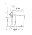
- FIG. 4 is a front view showing a part of the fixing device according to the present exemplary embodiment.
- FIG. 5 is a side view showing a part of the fixing device according to the present exemplary embodiment.
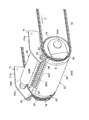
- FIG. 6 is a perspective view showing a part of the fixing device according to the present exemplary embodiment.
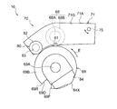
- FIG. 7 is a front view showing a state in which the heating roll is located at the retracted position in the fixing device shown in FIG. FIG.
- FIG. 8 is a perspective view showing a gripper according to this exemplary embodiment.
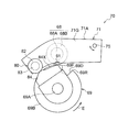
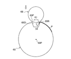
- FIG. 9 is a front view schematically showing the positional relationship between the heating roll and the pressure roll according to this exemplary embodiment.
- FIG. 10 is a front view schematically showing the positional relationship between the heating roll and the pressure roll according to this exemplary embodiment.
- FIG. 11 is a front view schematically showing the positional relationship between the heating roll and the pressure roll according to this exemplary embodiment.
- FIG. 12 is a front view schematically showing the positional relationship between the heating roll and the pressure roll according to this exemplary embodiment.
- FIG. 13 is a diagram showing a cam according to this exemplary embodiment.
- FIG. 14 is a diagram showing the relationship between the passage of time (horizontal axis) and the positional relationship (vertical axis) between the heating roll and the pressure roll.
- FIG. 15 is a front view schematically showing the positional relationship between the heating roll and the pressure roll according to the modified example.
- FIG. 1 is a schematic view showing a configuration of an image forming apparatus 10 according to this exemplary embodiment.
- the image forming apparatus 10 shown in FIG. 1 is an example of an image forming apparatus that forms an image on a recording medium.
- the image forming apparatus 10 is an electrophotographic image forming apparatus that forms a toner image (an example of an image) on a recording medium P.
- the image forming apparatus 10 includes an image forming unit 14 and a fixing device 16.
- each part (image forming part 14 and fixing device 16) of the image forming apparatus 10 will be described.
- the image forming unit 14 has a function of forming a toner image on the recording medium P.
- the image forming unit 14 includes a toner image forming unit 22 and a transfer device 17.
- the toner image forming unit 22 shown in FIG. 1 has a function of forming a toner image.
- a plurality of the toner image forming portions 22 are provided so as to form a toner image for each color.
- a total of four color toner image forming portions 22 of yellow (Y), magenta (M), cyan (C), and black (K) are provided.
- (Y), (M), (C), and (K) shown in FIG. 1 indicate components corresponding to the above colors.
- each part of the toner image forming part 22 (Y) is represented by reference numerals in FIG. 1 on behalf of the toner image forming part 22 of each color. Is attached.
- the toner image forming unit 22 of each color has a photoconductor drum 32 (photoreceptor) that rotates in one direction (for example, the counterclockwise direction in FIG. 1). Further, the toner image forming unit 22 of each color has a charging device 23, an exposure device 36, a developing device 38, and a removing device 40.
- the charger 23 charges the photoconductor drum 32.
- the exposure apparatus 36 exposes the photoconductor drum 32 charged by the charger 23 to form an electrostatic latent image on the photoconductor drum 32.
- the developing device 38 develops the electrostatic latent image formed on the photoconductor drum 32 by the exposure device 36 to form a toner image.
- the removing device 40 removes the toner remaining on the photoconductor drum 32 after the toner image is transferred to the transfer belt 24 described later.
- the transfer device 17 shown in FIG. 1 is a device that transfers the toner image formed by the toner image forming unit 22 to the recording medium P. Specifically, the transfer device 17 superimposes the toner image of the photoconductor drum 32 of each color on the transfer belt 24 as an intermediate transfer body for primary transfer, and transfers the superimposed toner image to the secondary transfer position T2 (described later). Secondary transfer is performed on the recording medium P in the transfer nip region 28A) of. More specifically, as shown in FIG. 1, the transfer device 17 includes a transfer belt 24, a primary transfer roll 26, a secondary transfer body 27, and a charger 60.
- the primary transfer roll 26 shown in FIG. 1 is a roll that transfers the toner image of the photoconductor drum 32 of each color to the transfer belt 24 at the primary transfer position T1 between the photoconductor drum 32 and the primary transfer roll 26. ..
- the toner image formed on the photoconductor drum 32 is transferred to the transfer belt at the primary transfer position T1 by applying a primary transfer electric field between the primary transfer roll 26 and the photoconductor drum 32. Transferred to 24.
- Transfer belt 24 In the transfer belt 24 shown in FIG. 1, the toner image is transferred from the photoconductor drum 32 of each color to the outer peripheral surface.
- the transfer belt 24 is configured as follows.
- the transfer belt 24 has an annular shape as shown in FIG.
- the transfer belt 24 is wound around a plurality of rolls 42 including the drive roll 42D, the winding rolls 42E, and 42F, and the posture is determined.
- the transfer belt 24 is rotated in the predetermined arrow A direction (hereinafter referred to as belt circumferential direction A) by rotationally driving the drive roll 42D by a drive unit (not shown). To do.
- belt circumferential direction A The specific configurations of the winding rolls 42E and 42F will be described later.
- the secondary transfer member 27 is an example of a transfer unit that transfers an image to a recording medium.
- the secondary transfer body 27 has a transfer body 28 and a pair of sprockets 29, as shown in FIG.
- the transfer cylinder 28 has a transfer nip region 28A as a sandwiching region for sandwiching the recording medium P with the outer peripheral surface of the transfer belt 24.
- the recording medium P is simplified and partially shown.
- the transfer nip region 28A is formed by winding the transfer belt 24 around the transfer cylinder 28.
- the transfer nip region 28A can also be said to be a contact region where the transfer belt 24 and the transfer cylinder 28 come into contact with each other.
- the transfer nip region 28A is set to the secondary transfer position T2 at which the toner image is transferred from the transfer belt 24 to the recording medium P. Further, the transfer cylinder 28 is conveyed by sandwiching the recording medium P with the transfer belt 24 in the transfer nip region 28A.
- the pair of sprockets 29 are arranged on both ends in the axial direction of the transfer cylinder 28.
- the transfer cylinder 28 is provided between the pair of sprockets 29.
- the pair of sprockets 29 are arranged coaxially with the transfer cylinder 28, and are configured to rotate integrally with the transfer cylinder 28.
- the secondary transfer body 27 is rotationally driven by a drive unit (not shown).
- one recess 28D in which the gripper 54 and the mounting member 55 described later of the transport portion 15 are housed is formed on the outer circumference of the transfer cylinder 28, one recess 28D in which the gripper 54 and the mounting member 55 described later of the transport portion 15 are housed is formed.
- a plurality of recesses 28D may be formed according to the arrangement interval of the grippers 54 along the circumferential direction C of the chain 52 described later.
- the charger 60 As shown in FIG. 3, the charger 60 is arranged inside the transfer belt 24 so as to face the transfer cylinder 28. Specifically, the charger 60 is a charger (so-called corotron type charger) that transfers a toner image by corona discharge to transfer the toner image of the belt 24.
- a charger so-called corotron type charger
- the charger 60 has a discharge wire 60A and a case 62 (housing).
- the discharge wire 60A has a linear shape having a length along the axial direction of the transfer cylinder 28.
- the case 62 surrounds the discharge wire. Specifically, the case 62 is formed in a box shape and has an opening 62C on the transfer cylinder 28 side (that is, the lower side).
- the case 62 includes a first wall 62A arranged on the side opposite to the transfer cylinder 28 with respect to the discharge wire 60A, and a pair of cases arranged on the upstream side and the downstream side of the belt circumferential direction A with respect to the discharge wire 60A. It has a second wall 62B and. Further, the case 62 has third walls (not shown) arranged on both ends in the length direction of the discharge wire 60A.
- the recording medium P is electrostatically adsorbed on the transfer belt 24 and the transfer cylinder 28 by applying a voltage to the discharge wire 60A to discharge the battery. Further, in the charger 60, the transfer belt 24 is charged by the discharge of the discharge wire 60A, and the toner image superimposed on the transfer belt 24 is recorded from the transfer belt 24 in the transfer nip region 28A (secondary transfer position T2). Transfer to P.
- the winding rolls 42E and 42F shown in FIGS. 1 and 3 are a pair of winding rolls on which the transfer belt 24 is wound inside the transfer belt 24. Specifically, the winding rolls 42E and 42F are arranged on the upstream side and the downstream side of the belt circumferential direction A with respect to the charger 60. Further, both the winding portions 43E and 43F wound around the winding rolls 42E and 42F of the transfer belt 24 are separated from the transfer cylinder 28.
- the fixing device 16 shown in FIG. 1 is a device that fixes the toner image transferred to the recording medium P by the transfer cylinder 28 to the recording medium P. More specifically, as shown in FIG. 1, the fixing device 16 includes a pressurizing body 67 as a pressurizing member, a heating roll 68 as a heating member, a transport portion 15, and a support 70 (FIG. 4). And FIG. 5) and a moving mechanism 80 (see FIGS. 4 and 5).
- the pressurizing body 67 has a pressurizing roll 69 and a pair of sprockets 19 as shown in FIG.
- the pressure roll 69 is an example of the first sandwiching portion.
- the pressurizing roll 69 has a function of sandwiching the recording medium P with the heating roll 68 and pressurizing the recording medium P.
- the pressure roll 69 has a shaft portion 69A and a roll portion 69B formed on the outer periphery of the shaft portion 69A, as shown in FIGS. 4, 5 and 6.
- the pair of sprockets 19 are arranged on both ends in the axial direction of the pressure roll 69.
- a pressure roll 69 is provided between the pair of sprockets 19.
- the pair of sprockets 19 are arranged coaxially with the pressure roll 69, and are configured to rotate integrally with the pressure roll 69.
- the pair of sprockets 19 are fixed to the shaft portion 69A on the lateral side of the roll portion 69B of the pressure roll 69 in the axial direction.
- the outer side in the axial direction means the side in the direction from the center in the axial direction to both ends in the axial direction.
- only one sprocket 19 of the pair of sprockets 19 is shown.
- the sprocket 19 is not shown.
- the pressure roll 69 is rotationally driven by, for example, a drive unit (not shown) through the shaft unit 69A in the direction of arrow E shown in FIGS. 4 and 6. Further, as shown in FIG. 6, one recess 69D in which the gripper 54 of the transport portion 15 and the mounting member 55 are housed is formed on the outer periphery of the pressure roll 69.
- the recess 69D opens radially outward of the pressure roll 69, as shown in FIGS. 4 and 6.
- the recess 69D has a corner portion 69F (hereinafter, referred to as a front end edge 69F) at the downstream end of the pressure roll 69 in the rotation direction. Further, the recess 69D has a corner portion 69R (hereinafter, referred to as a rear end edge 69R) at the upstream end of the pressure roll 69 in the rotation direction.
- a plurality of recesses 69D may be formed according to the arrangement interval of the grippers 54 along the circumferential direction C of the chain 52 described later.
- the heating roll 68 shown in FIG. 4 is an example of the second sandwiching portion.
- the heating roll 68 has a function of heating the recording medium P.
- the heating roll 68 has a shaft portion 68A and a roll portion 68B formed on the outer periphery of the shaft portion 68A.
- the outer peripheral surface of the roll portion 68B of the heating roll 68 comes into contact with the outer peripheral surface of the roll portion 69B of the pressure roll 69 (an example of the outer surface of the first sandwiching portion) to heat the product.
- a fixing nip region 61 (an example of the sandwiching region) that sandwiches the recording medium P is formed by the roll 68 and the pressure roll 69.
- the support 70 shown in FIG. 5 has a function of supporting the pressurizing body 67 and the heating roll 68. Specifically, the support 70 has a first frame 71, a pair of second frames 72, and a bottom wall 73, as shown in FIG. Note that FIG. 5 shows only one of the second frames 72 of the pair of second frames 72.
- the bottom wall 73 is arranged below the pressurizing body 67.
- the bottom wall 73 is formed in a plate shape having a thickness in the vertical direction.
- the first frame 71 has a pair of side walls 71A and a connecting wall 71B.
- the pair of side walls 71A are arranged on both ends in the axial direction of the heating roll 68. In FIG. 5, only one side wall 71A of the pair of side wall 71A is shown.
- the side wall 71A is arranged above the pressure roll 69. Further, the side wall 71A extends along the chain 52 toward the upstream side in the transport direction with respect to the fixing nip region 61 in the axial view of the heating roll 68 (see FIG. 6), and is in the transport direction with respect to the fixing nip region 61. It extends along the circumferential direction of the pressure roll 69 toward the downstream side (see FIG. 4).
- the connecting wall 71B extends from one of the pair of side walls 71A to the other along the axial direction of the heating roll 68.
- the connecting wall 71B connects the upper portions of the pair of side walls 71A to each other.
- the pair of side walls 71A rotatably supports the heating roll 68.
- a cam follower 82 which will be described later, is provided on each outer surface 71G of the pair of side walls 71A.
- the outer surface 71G of the side wall 71A is a surface opposite to the inner surface 71N on which the pair of side walls 71A face each other.
- the pair of second frames 72 are provided on the bottom wall 73 so as to extend upward from the bottom wall 73 on the outside of the pair of side walls 71A.
- the outside of the pair of side walls 71A is the side opposite to the side facing the pair of side walls 71A (arrow TA in FIG. 5).
- the pair of second frames 72 are arranged on both ends in the axial direction of the pressurizing body 67 and the heating roll 68.
- the second frame 72 is formed in a plate shape having a thickness in the axial direction of the pressure roll 69.
- the pair of second frames 72 rotatably support the pressure roll 69. Specifically, the pair of second frames 72 rotatably support the shaft portions 69A of the pressure roll 69 on both end sides in the axial direction. More specifically, the pair of second frames 72 rotatably support the shaft portion 69A of the pressure roll 69 on the axially outer side (specifically, the axially outer side described later) of the roll portion 69B. There is.
- the pair of second frames 72 rotatably support the first frame 71 around the axis of the rotating shaft 75 via the rotating shaft 75.
- the rotating shaft 75 is arranged on the upstream side in the transport direction with respect to the fixing nip region 61.
- the "upstream side in the transport direction with respect to the fixing nip region 61" is an example of "one side in the transport direction with respect to the sandwiching region”.
- the heating roll 68 has a nip position (an example of the first position) shown in FIGS. 4 and 9 and a retracted position (second position) shown in FIGS. 7 and 10.
- the first frame 71 is supported on the upstream side of the fixing nip region 61 in the transport direction so as to be movable from the example).
- the heating roll 68 is movable between the nip position shown in FIGS. 4 and 9 and the retracted position shown in FIGS. 7 and 10 with the upstream side in the transport direction with respect to the fixing nip region 61 as a fulcrum. ing.
- the nip position is a position where the distance of the heating roll 68 with respect to the pressure roll 69 is the distance forming the fixing nip region 61.
- the retracted position is a position where the distance of the heating roll 68 with respect to the pressure roll 69 is longer than the distance at the nip position.
- the distance of the heating roll 68 with respect to the pressure roll 69 specifically means the distance between the axes of the pressure roll 69 and the heating roll 68.
- the first frame 71 is pushed or pulled by the elastic force of an elastic member such as a spring so that the heating roll 68 is located at the nip position. That is, the heating roll 68 is pushed or pulled toward the nip position.
- the toner image formed on the recording medium P is fixed on the recording medium P by heating and pressurizing the recording medium P with the heating roll 68 and the pressure roll 69.
- the transport unit 15 shown in FIGS. 1 to 3 and 6 has a function of transporting the recording medium P. Specifically, the transport unit 15 has a function of transporting the recording medium P and passing it through the transfer nip region 28A (see FIG. 3) and the fixing nip region 61.
- the transport unit 15 has a pair of chains 52 and a gripper 54, as shown in FIGS. 1 and 2.
- the gripper 54 is an example of a holding portion that holds the front end side of the recording medium.
- the chain 52 and the gripper 54 are shown in a simplified manner.
- the pair of chains 52 are formed in an annular shape as shown in FIG. As shown in FIGS. 2 and 6, the pair of chains 52 are arranged at intervals in the device depth direction (D direction in FIG. 2).
- the pair of chains 52 are wound around a pair of sprockets 29 (see FIG. 2) included in the secondary transfer body 27 and a pair of sprockets 19 (see FIG. 6) included in the pressurizing body 67, respectively. ..
- the secondary transfer body 27 having the pair of sprockets 29 and the pressurizing body 67 having the pair of sprockets 19 rotate to rotate the chain 52 in the circumferential direction C (arrows C in FIGS. 1, 2 and 6). It is configured to go around in the direction).
- a mounting member 55 to which the gripper 54 is mounted is hung on the pair of chains 52 along the depth direction of the device.
- a plurality of mounting members 55 are fixed to a pair of chains 52 at predetermined intervals along the circumferential direction (circumferential direction C) of the chain 52.
- a plurality of grippers 54 are attached to the attachment member 55 at predetermined intervals along the device depth direction.
- the gripper 54 is attached to the chain 52 via the attachment member 55.
- the gripper 54 has a function of holding the front end portion of the recording medium P.
- the gripper 54 has a claw 54A and a claw base 54B, as shown in FIG.
- the gripper 54 is configured to hold the recording medium P by sandwiching the front end portion of the recording medium P between the claw 54A and the claw base 54B.
- the gripper 54 can be said to be an example of a holding portion that holds the recording medium P in the thickness direction.
- the gripper 54 holds the front end portion of the recording medium P outside the image area of the recording medium P.
- the image area of the recording medium P is an area in which the toner image is transferred in the recording medium P.
- the claw 54A is pressed against the claw base 54B by a spring or the like, and the claw 54A is opened and closed against the claw base 54B by the action of a cam or the like.
- the transport unit 15 holds the front end portion of the recording medium P sent from the storage unit (not shown) in which the recording medium P is housed by the gripper 54 as shown in FIG.
- the chain 52 orbits in the circumferential direction C while the gripper 54 holds the front end portion of the recording medium P, so that the gripper 54 is moved to transport the recording medium P, and the gripper 54 transports the recording medium P. Is passed through the transfer nip region 28A together with the gripper 54 while holding the above.
- the gripper 54 moves in the rotation direction of the transfer cylinder 28 integrally with the transfer cylinder 28 while being housed in the recess 28D of the transfer cylinder 28.
- the transport unit 15 passes the transfer nip region 28A through the recording medium P, and then passes the recording medium P together with the gripper 54 through the fixing nip region 61 while holding the recording medium P by the gripper 54.
- the gripper 54 moves in the rotation direction of the pressure roll 69 integrally with the pressure roll 69 while being housed in the recess 69D of the pressure roll 69. ..
- the moving mechanism 80 shown in FIGS. 4 and 5 is an example of a moving mechanism that moves the heating roll 68 relative to the pressure roll 69.
- the moving mechanism 80 is a mechanism for moving the heating roll 68.
- the moving mechanism 80 has a cam follower 82 and a cam 84, as shown in FIGS. 4 and 5.
- the cam follower 82 is provided on the outer surface 71G of each of the pair of side walls 71A in the first frame 71. Specifically, as shown in FIG. 5, the cam follower 82 is rotatably supported by the tip end portion of the shaft portion 83 protruding from the outer surface 71G of the side wall 71A to the outside of the side wall 71A.
- the cam follower 82 is provided on the downstream side in the transport direction with respect to the fixing nip region 61.
- the "downstream side in the transport direction with respect to the fixing nip region 61" is an example of "the other side in the transport direction with respect to the sandwiching region”. It can be said that the cam follower 82 is arranged on the downstream side in the rotation direction of the pressure roll 69 with respect to the heating roll 68. That is, the cam follower 82 is displaced with respect to the heating roll 68 toward the downstream side in the rotation direction of the pressure roll 69 by a predetermined rotation angle of the pressure roll 69.
- the cam follower 82 is formed in a circular disk shape in the axial direction of the heating roll 68.
- the cam follower 82 has an outer diameter smaller than the outer diameter of the heating roll 68 and the outer diameter of the pressure roll 69. Note that, in FIGS. 4 and 5, only one of the pair of cam followers 82 is shown.
- the cam 84 is provided on the pressure roll 69 as shown in FIGS. 4 and 5. Specifically, the cam 84 is provided at both ends of the shaft portion 69A of the pressure roll 69. More specifically, as shown in FIG. 5, the cam 84 is fixed between the sprocket 19 and the second frame 72 in the shaft portion 69A of the pressure roll 69. Note that, in FIGS. 4 and 5, only one of the pair of cams 84 is shown.
- the cam 84 is arranged on the downstream side in the rotation direction of the pressure roll 69 with respect to the recess 69D of the pressure roll 69. That is, the cam 84 is displaced with respect to the recess 69D of the pressure roll 69 toward the downstream side in the rotation direction of the pressure roll 69 by a predetermined rotation angle of the pressure roll 69. This amount of deviation corresponds to the amount of deviation of the cam follower 82 with respect to the heating roll 68.
- the cam 84 rotates integrally with the pressure roll 69 and comes into contact with the cam follower 82 at a position facing the cam follower 82 (a position diagonally upper left in FIG. 4). As shown in FIG. 13, the cam 84 has a cam surface 84X having a different distance from the rotation shaft 69P of the pressure roll 69.
- the cam surface 84X has the longest distance from the rotation shaft 69P of the pressure roll 69 in the portion 84B. That is, the cam surface 84X projects most outward in the radial direction of the pressure roll 69 in the portion 84B.
- the portion 84A is a portion arranged on the downstream side in the rotation direction of the pressure roll 69 with respect to the portion 84B. Further, the distance of the pressure roll 69 from the rotation shaft 69P gradually decreases from the portion 84B to the portion 84C.
- the portion 84C is a portion arranged on the upstream side in the rotation direction of the pressure roll 69 with respect to the portion 84B. The length along the circumferential direction of the pressure roll 69 from the portion 84B to the portion 84C is shorter than the length along the circumferential direction of the pressure roll 69 from the portion 84B to the portion 84A.
- the average inclination of the cam surface 84X from the portion 84B to the portion 84C is smaller than the average of the inclinations of the cam surface 84X from the portion 84B to the portion 84A.
- the distance of the pressure roll 69 from the rotating shaft 69P is constant between the portion 84C and the portion 84D.
- the portion 84D is a portion arranged on the upstream side in the rotation direction of the pressure roll 69 with respect to the portion 84C.
- the cam surface 84X comes into contact with the cam follower 82 as the pressure roll 69 rotates, and the heating roll 68 is moved between the nip position and the retracted position.
- the heating roll 68 operates as follows by changing the contact position of the cam 84 with respect to the cam follower 82.
- FIG. 9 shows the positional relationship between the heating roll 68 and the pressure roll 69 at the starting point A1.
- the cam 84 contacts the cam follower 82 at portion 84A in FIG.
- the gripper 54 is also in a state before entering the fixing nip region 61. Therefore, it can be said that the heating roll 68 starts moving from the nip position to the retracted position before the gripper 54 enters the fixing nip region 61.
- the heating roll 68 is located at the retracted position (see FIG. 10). That is, when the front end edge 69F of the recess 69D starts to enter the fixing nip region 61, the heating roll 68 is located at the retracted position.
- FIG. 10 shows the positional relationship between the heating roll 68 and the pressure roll 69 at the time when the recess 69D starts entering the fixing nip region 61 (hereinafter referred to as the entry time B1).
- the cam 84 contacts the cam follower 82 at the portion 84B in FIG.
- the fixing nip region 61 in a state where the heating roll 68 is not in contact with the pressure roll 69 is a place or a range in which the fixing nip region 61 is formed when the heating roll 68 comes into contact with the pressure roll 69. Means.
- the gripper 54 Since the gripper 54 enters the fixing nip area 61 later than the recess 69D, at the time of entry B1, the gripper 54 is in a state before entering the fixing nip area 61 as shown in FIG.
- the heating roll 68 moves to the nip position (hereinafter, this point is referred to as an end point C1). Specifically, the heating roll 68 moves to the nip position before the recess 69D exits the anchoring nip region 61. More specifically, the heating roll 68 moves to the nip position after the front edge 69F of the recess 69D exits the anchoring nip region 61 and before the rear edge 69R enters the anchoring nip region 61. ..
- the heating roll 68 moves to the nip position after the gripper 54 has entered the fixing nip region 61. Specifically, the heating roll 68 moves to the nip position before the gripper 54 exits the anchoring nip region 61.
- the heating roll 68 is in non-contact with the gripper 54 housed in the recess 69D. That is, the heating roll 68 moves to a nip position that is not in contact with the gripper 54 located in the fixing nip region 61.
- FIG. 11 shows the positional relationship between the heating roll 68 and the pressure roll 69 at the end point C1.
- the cam 84 contacts the cam follower 82 at the portion 84C in FIG.
- the heating roll 68 maintains the state of being located at the nip position. Therefore, the heating roll 68 is located at the nip position when the rear end edge 69R of the recess 69D enters the fixing nip region 61 and exits the fixing nip region 61.
- the heating roll 68 is located at the nip position when the gripper 54 exits the fixing nip region 61.
- FIG. 12 shows the positional relationship between the heating roll 68 and the pressure roll 69 at the time when the rear end edge 69R of the recess 69D exits from the fixing nip region 61 (hereinafter referred to as the exit time D1).
- the cam 84 contacts the cam follower 82 at portion 84D in FIG.
- FIG. 14 shows the relationship between the passage of time and the positional relationship between the heating roll 68 and the pressure roll 69 (specifically, the distance between the axes of the heating roll 68 and the pressure roll 69). ..
- the passage of time is shown on the horizontal axis
- the positional relationship between the heating roll 68 and the pressure roll 69 is shown on the vertical axis.
- “R 1 ”, “R 2 ”, “x” and “y” in FIG. 14 are “radius of heating roll 68”, “radius of pressure roll 69”, “evacuation distance” and “heating roll 68”, respectively.
- “Compression amount of elastic layer” is shown. Further, arrows A1 and C1 in FIG.
- FIG. 14 indicate a start point A1 and an end point C1, respectively. Further, arrows B1 and D1 in FIG. 14 indicate an entry time point B1 and an exit time point D1, respectively.
- the horizontal axis of FIG. 14 may be regarded as a change in the rotation angle of the pressure roll 69.
- the central point 100A of the period 100 from the start point A1 to the end point C1 becomes the anchoring nip region of the recess 69D as shown in FIG. It precedes the center point 200A of the period 200 passing through 61.
- the heating roll 68 moves to.
- the heating roll 68 moves.
- the relative movement amount of the heating roll 68 from the retracted position to the nip position per unit time is smaller than the relative movement amount of the heating roll 68 from the nip position to the retracted position per unit time. That is, in FIG. 14, the slope of the line LB from the arrow B1 to the arrow C1 is smaller than the slope of the line LA from the arrow A1 to the arrow B1.
- the recess 69D Since the heating roll 68 moves to the nip position after the rear end edge 69R exits the fixing nip region 61, the timing of sandwiching the recording medium P between the pressure roll 69 and the heating roll 68 is delayed.
- the heating roll 68 moves so that the center point 100A precedes the center point 200A, for example, the rear end edge 69R of the recess 69D forms the fixing nip region 61.
- the heating roll 68 moves to the nip position before exiting. Therefore, the timing of sandwiching the recording medium P between the pressure roll 69 and the heating roll 68 is earlier than that of the first comparative example.
- the toner image is fixed from the front end side of the recording medium P, so that the range in which the toner image can be fixed to the recording medium P becomes wider. In other words, according to this exemplary embodiment, the range in which the toner image can be formed on the recording medium P is wider than that in the first comparative example.
- the heating roll is such that the central point 100A of the period from the start point A1 to the end point C1 precedes the central point 300A of the period during which the gripper 54 passes through the fixing nip region 61. 68 moves.
- the center point 100A of the period from the start point A1 to the end point C1 coincides with the center point 300A of the period during which the gripper 54 passes through the fixing nip region 61.
- the heating roll 68 moves to the nip position after the rear end edge 69R of the recess 69D exits the fixing nip region 61, the timing of sandwiching the recording medium P between the pressure roll 69 and the heating roll 68 is delayed.
- the heating roll 68 moves so that the center point 100A precedes the center point 300A, for example, the rear end edge 69R of the recess 69D forms the fixing nip region 61. Since the heating roll 68 moves to the nip position before exiting, the timing of sandwiching the recording medium P between the pressure roll 69 and the heating roll 68 is earlier than in the second comparative example.
- the heating roll 68 moves to the nip position before the rear end edge 69R of the recess 69D exits the fixing nip region 61, the rear end edge 69R of the recess 69D covers the fixing nip region 61.
- the range in which the recording medium P is sandwiched between the pressure roll 69 and the heating roll 68 becomes wider.
- the heating roll 68 moves to the nip position before the gripper 54 exits the fixing nip region 61, the heating roll 68 moves to the nip position after the gripper 54 exits the fixing nip region 61.
- the range in which the recording medium P is sandwiched between the pressurizing roll 69 and the heating roll 68 is wider than that of the configuration of moving to.
- the heating roll 68 moves to a nip position that is not in contact with the gripper 54 located in the fixing nip region 61. Therefore, the interference between the heating roll 68 and the gripper 54 is suppressed as compared with the configuration in which the heating roll 68 is in contact with the gripper 54 located in the fixing nip region 61 at the nip position.
- the heating roll 68 can be moved to the upstream side in the transport direction with respect to the fixing nip region 61 as a fulcrum, and the cam follower 82 is provided on the downstream side in the transport direction with respect to the fixing nip region 61. Has been done.
- the fulcrum and the cam follower 82 are arranged on one side in the transport direction with respect to the fixing nip region 61, the fulcrum and the force point are separated from each other, so that the heating roll 68 is moved with a small load. Further, as compared with the configuration in which the cam follower 82 is provided on the upstream side in the transport direction with respect to the fixing nip region 61, it is suppressed that the cam follower 82 interferes with the member arranged on the upstream side in the transport direction with respect to the fixing nip region 61. To.
- the relative movement amount of the heating roll 68 from the retracted position to the nip position per unit time is smaller than the relative movement amount of the heating roll 68 from the nip position to the retracted position per unit time. ..
- the relative movement amount of the heating roll 68 from the retracted position to the nip position per unit time is larger than the relative movement amount of the heating roll 68 from the nip position to the retracted position per unit time, as compared with the configuration of the heating roll 68.
- the 68 is quickly separated from the pressure roll 69 and the heating roll 68 is slowly brought closer to the pressure roll 69. As a result, vibration due to contact between the heating roll 68 and the pressure roll 69 is suppressed.
- heating roll 68 (Modified example of operation of heating roll 68)
- the heating roll 68 has moved to the nip position after the recess 69D has entered the anchoring nip region 61, but is not limited to this.
- the heating roll 68 may move to the nip position after the holding position 54P of the recording medium P by the gripper 54 has entered the fixing nip region 61. In this configuration, the heating roll 68 moves to the nip position before the holding position 54P exits the anchoring nip region 61.
- the center point 500A of the period 500 from the start point A1 to the time point E1 is the center point 400A of the period 400 in which the holding position 54P of the recording medium P by the gripper 54 passes through the fixing nip region 61. To precede.
- the center point 500A of the period 500 from the start point A1 to the time point E1 is the center point of the period 400 in which the holding position 54P of the recording medium P by the gripper 54 passes through the fixing nip region 61.
- the heating roll 68 moves so as to precede 400A.
- the heating roll 68 moves so that the center point 500A precedes the center point 400A. Therefore, for example, the center point 500A and the center point 400A coincide with each other (third comparison).
- the timing of sandwiching the recording medium P between the pressurizing roll 69 and the heating roll 68 is earlier.
- the range in which the toner image can be fixed to the recording medium P is widened. In other words, according to this exemplary embodiment, the range in which the toner image can be formed on the recording medium P is wider than that in the third comparative example.
- the heating roll 68 is moved, but the pressure roll 69 may be moved. That is, the heating roll 68 may move relative to the pressure roll 69.
- the rotating shaft 75 is arranged on the upstream side in the transport direction with respect to the fixing nip region 61, but the present invention is not limited to this.
- the rotating shaft 75 may be arranged on the downstream side in the transport direction with respect to the fixing nip region 61.
- the cam follower 82 is arranged, for example, on the upstream side in the transport direction with respect to the fixing nip region 61.
- the gripper 54 holds the front end portion of the recording medium P, but the present invention is not limited to this.
- the gripper 54 may be configured to hold the front end side of the recording medium P from the side end side of the recording medium P.
- the front end side of the recording medium is a portion of the recording medium on the downstream side (front side) from the center in the transport direction.
- the transport device As an example of the transport device, a case where the fixing device has a transport function for transporting the recording medium P and a fixing function for fixing the image on the recording medium P has been described. Not limited to.
- the transport device may be, for example, a device having only a transport function, or a device having a function other than the fixing function and a transport function.
Landscapes
- Physics & Mathematics (AREA)
- General Physics & Mathematics (AREA)
- Engineering & Computer Science (AREA)
- Mechanical Engineering (AREA)
- Fixing For Electrophotography (AREA)
- Electrostatic Charge, Transfer And Separation In Electrography (AREA)
- Feeding Of Articles By Means Other Than Belts Or Rollers (AREA)
- Paper Feeding For Electrophotography (AREA)
- Delivering By Means Of Belts And Rollers (AREA)
Abstract
搬送装置は、第一挟み部と、第二挟み部と、搬送部と、移動機構と、を備える。第二挟み部は第一挟み部とで記録媒体を挟む挟み領域を形成し、第一位置と第二位置との間を相対移動可能である。搬送部は、記録媒体の前端側を保持部で保持したまま挟み領域を通過させる。移動機構は、保持部による記録媒体の保持位置が挟み領域に進入する前に第一位置から第二位置への第二挟み部の相対移動を開始させてから、保持位置が挟み領域に進入した後に第一位置へ第二挟み部を相対移動させるまでの期間の中央点が、保持位置が挟み領域を通過する期間の中央点に対して先行するように、第二挟み部を相対移動させる。
Description
本発明は、搬送装置、定着装置、及び画像形成装置に関する。
特許文献1には、対となって配置された第1定着ロールと第2定着ロールからなり、少なくとも一方が加熱ロールであり、かつ、少なくとも一方の定着ロールの表層が交換可能である定着ロール対と、貼着部材を備える貼着手段と、記録媒体および前記貼着手段の少なくとも一方を帯電させる帯電手段と、記録媒体の搬送方向先端部を把持部によって貼着手段に物理的に固定する固定手段とを有し、帯電手段により、貼着部材と記録媒体とを静電吸着させ、かつ固定手段により、記録媒体を貼着手段に固定させた後に、定着ロール対によって、貼着手段とともに挟持して搬送することにより、画像を定着させる定着装置が開示されている。
定着装置等の搬送装置としては、加熱ロール等の第一挟み部と、第一挟み部とで記録媒体を挟む挟み領域を形成し、第一挟み部に対する距離が挟み領域を形成する距離となる第一位置と、第一挟み部に対する距離が該第一位置における距離よりも長い第二位置と、の間を相対移動可能な加圧ロール等の第二挟み部と、記録媒体の前端側を保持する保持部を移動させて該記録媒体を搬送し、保持部を挟み領域を通過させる搬送部と、を有する構成が考えられる。
当該構成において、第一位置から第二位置への第二挟み部の相対移動を開始してから第二挟み部を第一位置へ相対移動させるまでの期間の中央点が、保持部による記録媒体の保持位置が挟み領域を通過する期間の中央点と一致する場合では、第一挟み部と第二挟み部とで記録媒体を挟むタイミングが遅くなる。
本発明の一態様は、第一位置から第二位置への第二挟み部の相対移動を開始してから第二挟み部を第一位置へ相対移動させるまでの期間の中央点が、保持位置が挟み領域を通過する期間の中央点と一致する構成に比べ、第一挟み部と第二挟み部とで記録媒体を挟むタイミングを早めることに関する。
本発明の第1態様の搬送装置は、第一挟み部と、外面を有する第二挟み部であって、前記外面が前記第一挟み部の外面に接触することで前記第一挟み部と前記第二挟み部とで記録媒体を挟む挟み領域を形成し、前記第二挟み部の前記第一挟み部に対する距離が前記挟み領域を形成する距離となる第一位置と、前記第二挟み部の前記第一挟み部に対する距離が前記第一位置における距離よりも長い第二位置と、の間を相対移動可能な第二挟み部と、前記記録媒体の前端側を保持する保持部を有し、前記保持部を移動させて前記記録媒体を搬送し、前記保持部で前記記録媒体を保持したまま前記記録媒体及び前記保持部に前記挟み領域を通過させる搬送部と、前記保持部による前記記録媒体の保持位置が前記挟み領域に進入する前に前記第一位置から前記第二位置への前記第二挟み部の相対移動を開始させてから、前記保持位置が前記挟み領域に進入した後に前記第一位置へ前記第二挟み部を相対移動させるまでの期間の中央点が、前記保持位置が前記挟み領域を通過する期間の中央点に対して先行するように、前記第二挟み部を相対移動させる移動機構と、を備える。
第2態様の搬送装置では、前記移動機構は、前記保持位置が前記挟み領域から退出する前に、前記第一位置へ前記第二挟み部を相対移動させてもよい。
本発明の第3態様の搬送装置は、第一挟み部と、外面を有する第二挟み部であって、前記外面が前記第一挟み部の外面に接触することで前記第一挟み部と前記第二挟み部とで記録媒体を挟む挟み領域を形成し、前記第二挟み部の前記第一挟み部に対する距離が前記挟み領域を形成する距離となる第一位置と、前記第二挟み部の前記第一挟み部に対する距離が前記第一位置における距離よりも長い第二位置と、の間を相対移動可能な第二挟み部と、前記記録媒体の前端側を保持する保持部を有する搬送部であって、前記保持部を移動させて前記記録媒体を搬送し、前記保持部で前記記録媒体を保持したまま前記記録媒体及び前記保持部に前記挟み領域を通過させる搬送部と、前記第二挟み部を相対移動させる移動機構であって、前記保持部が前記挟み領域に進入する前に前記第一位置から前記第二位置への前記第二挟み部の相対移動を開始させてから、前記保持部が前記挟み領域に進入した後に前記第一位置へ前記第二挟み部を相対移動させるまでの期間の中央点が、前記保持部が前記挟み領域を通過する期間の中央点に対して先行するように、前記第二挟み部を相対移動させる移動機構と、を備える。
第4態様では、前記移動機構は、前記保持部が前記挟み領域から退出する前に、前記第一位置へ前記第二挟み部を相対移動させてもよい。
本発明の第5態様の搬送装置は、回転方向に回転し、外面の一部に凹部を有する第一挟み部と、外面を有する第二挟み部であって、前記第二挟み部の前記外面が前記第一挟み部の前記外面に接触することで前記第一挟み部と前記第二挟み部とで記録媒体を挟む挟み領域を形成し、前記第二挟み部の前記第一挟み部に対する距離が前記挟み領域を形成する距離となる第一位置と、前記第二挟み部の前記第一挟み部に対する距離が前記第一位置における距離よりも長い第二位置と、の間を相対移動可能な第二挟み部と、前記記録媒体の前端側を保持する保持部を有する搬送部であって、前記保持部を前記凹部に収容した状態で前記回転方向へ移動させて前記記録媒体を搬送し、前記保持部で前記記録媒体を保持したまま前記記録媒体及び前記保持部に前記挟み領域を通過させる搬送部と、前記第二挟み部を相対移動させる移動機構であって、前記凹部が前記挟み領域に進入する前に前記第一位置から前記第二位置への前記第二挟み部の相対移動を開始させてから、前記凹部が前記挟み領域に進入した後に前記第一位置へ前記第二挟み部を相対移動させるまでの期間の中央点が、前記凹部が前記挟み領域を通過する期間の中央点に対して先行するように、前記第二挟み部を相対移動させる移動機構と、を備える。
第6態様では、前記移動機構は、前記凹部が前記挟み領域から退出する前に、前記第一位置へ前記第二挟み部を相対移動させてもよい。
第7態様では、前記移動機構は、前記挟み領域に位置する前記保持部に対して前記第二挟み部が非接触である前記第一位置へ前記第二挟み部を相対移動させてもよい。
第8態様では、前記第二挟み部は、前記挟み領域に対する搬送方向の一方側を支点に前記第一位置と前記第二位置との間を相対移動可能とされ、前記移動機構は、前記挟み領域に対する前記搬送方向の他方側において前記第二挟み部に設けられたカムフォロアと、前記第一挟み部に設けられ、前記カムフォロアに接触し前記第一挟み部の回転に伴って前記第二挟み部を相対移動させるカムと、を有していてもよい。
第9態様では、前記搬送方向において前記挟み領域よりも上流側に前記支点が配置されてもよく、前記カムフォロアは、前記搬送方向において前記挟み領域よりも下流側で、前記第二挟み部に設けられていてもよい。
第10態様では、前記第二挟み部は、単位時間あたりの前記第一位置から前記第二位置への相対移動量よりも、単位時間あたりの前記第二位置から前記第一位置への相対移動量が小さくてもよい。
第11態様は、前記第一挟み部が、加圧ロールであり、前記第二挟み部が、加熱ロールである搬送装置としての定着装置である。
本発明の第12態様の画像形成装置は、記録媒体に画像を転写する転写部と、前記記録媒体に転写された画像を前記記録媒体に定着する第11態様に記載の定着装置と、を備える。
第1態様の構成によれば、第一位置から第二位置への第二挟み部の相対移動を開始してから第二挟み部を第一位置へ相対移動させるまでの期間の中央点が、保持位置が挟み領域を通過する期間の中央点と一致する構成に比べ、第一挟み部と第二挟み部とで記録媒体を挟むタイミングを早めることができる。
第2態様の構成によれば、保持位置が挟み領域から退出した後に、移動機構が第二挟み部を第一位置へ相対移動させる構成に比べ、第一挟み部と第二挟み部とで記録媒体を挟む範囲が広くなる。
第3態様の構成によれば、第一位置から第二位置への第二挟み部の相対移動を開始してから第二挟み部を第一位置へ相対移動させるまでの期間の中央点が、保持部が挟み領域を通過する期間の中央点と一致する構成に比べ、第一挟み部と第二挟み部とで記録媒体を挟むタイミングを早めることができる。
第4態様の構成によれば、保持部が挟み領域から退出した後に、移動機構が第二挟み部を第一位置へ相対移動させる構成に比べ、第一挟み部と第二挟み部とで記録媒体を挟む範囲が広くなる。
第5態様の構成によれば、第二挟み部を第一位置から第二位置への相対移動を開始して第一位置へ相対移動させるまでの期間の中央点が、凹部が挟み領域を通過する期間の中央点と一致する構成に比べ、第一挟み部と第二挟み部とで記録媒体を挟むタイミングを早めることができる。
第6態様の構成によれば、凹部が挟み領域から退出した後に、移動機構が第二挟み部を第一位置へ相対移動させる構成に比べ、第一挟み部と第二挟み部とで記録媒体を挟む範囲が広くなる。
第7態様の構成によれば、挟み領域に位置する保持部に接触する第一位置へ第二挟み部を相対移動させる構成に比べ、第二挟み部と保持部との干渉が抑制される。
第8態様の構成によれば、支点とカムフォロアとが挟み領域に対する搬送方向の一方側に配置された構成に比べ、小さい荷重で第二挟み部を移動させることができる。
第9態様の構成によれば、搬送方向において挟み領域の上流側でカムフォロアが第二挟み部に設けられている構成に比べ、搬送方向において挟み領域の上流側に配置された部材とカムフォロアが干渉することが抑制される。
第10態様の構成によれば、移動機構による単位時間当たりの第一位置から第二位置への第二挟み部の相対移動量よりも、移動機構による単位時間当たりの第二位置から第一位置への第二挟み部の相対移動量が大きい構成に比べ、第二挟み部を第一挟み部から素早く離間させ、第二挟み部を第一挟み部へゆっくり接近させることができる。
第11態様の構成によれば、第一位置から第二位置への第二挟み部の相対移動を開始してから第一位置へ相対移動させるまでの期間の中央点が、保持位置が挟み領域を通過する期間の中央点と一致する構成に比べ、画像を記録媒体に定着可能な範囲を広くできる。
第12態様の構成によれば、第一位置から第二位置への第二挟み部の相対移動を開始してから第一位置へ相対移動させるまでの期間の中央点が、保持位置が挟み領域を通過する期間の中央点と一致する構成に比べ、画像を記録媒体に形成可能な範囲を広くできる。
以下に、本発明に係る例示的実施形態の一例を図面に基づき説明する。
(画像形成装置10)
本例示的実施形態に係る画像形成装置10の構成を説明する。図1は、本例示的実施形態に係る画像形成装置10の構成を示す概略図である。
本例示的実施形態に係る画像形成装置10の構成を説明する。図1は、本例示的実施形態に係る画像形成装置10の構成を示す概略図である。
図1に示される画像形成装置10は、記録媒体に画像を形成する画像形成装置の一例である。具体的には、画像形成装置10は、記録媒体Pにトナー像(画像の一例)を形成する電子写真式の画像形成装置である。さらに具体的には、画像形成装置10は、画像形成部14と、定着装置16と、を備えている。以下、画像形成装置10の各部(画像形成部14、及び定着装置16)について説明する。
(画像形成部14)
画像形成部14は、トナー像を記録媒体Pに形成する機能を有している。具体的には、画像形成部14は、トナー像形成部22と、転写装置17と、を有している。
画像形成部14は、トナー像を記録媒体Pに形成する機能を有している。具体的には、画像形成部14は、トナー像形成部22と、転写装置17と、を有している。
(トナー像形成部22)
図1に示されるトナー像形成部22は、トナー像を形成する機能を有している。このトナー像形成部22は、色ごとにトナー像を形成するように複数備えられている。本例示的実施形態では、イエロー(Y)、マゼンタ(M)、シアン(C)、ブラック(K)の計4色のトナー像形成部22が設けられている。図1に示す(Y)、(M)、(C)、(K)は、上記各色に対応する構成部分を示している。
図1に示されるトナー像形成部22は、トナー像を形成する機能を有している。このトナー像形成部22は、色ごとにトナー像を形成するように複数備えられている。本例示的実施形態では、イエロー(Y)、マゼンタ(M)、シアン(C)、ブラック(K)の計4色のトナー像形成部22が設けられている。図1に示す(Y)、(M)、(C)、(K)は、上記各色に対応する構成部分を示している。
なお、各色のトナー像形成部22は、用いるトナーを除き同様に構成されているので、各色のトナー像形成部22を代表して、図1ではトナー像形成部22(Y)の各部に符号を付している。
各色のトナー像形成部22は、具体的には、一方向(例えば、図1における反時計回り方向)に回転する感光体ドラム32(感光体)を有している。さらに、各色のトナー像形成部22は、帯電器23と、露光装置36と、現像装置38と、除去装置40と、を有している。
各色のトナー像形成部22では、帯電器23が、感光体ドラム32を帯電させる。露光装置36が、帯電器23によって帯電された感光体ドラム32を露光して、感光体ドラム32に静電潜像を形成する。現像装置38が、露光装置36によって感光体ドラム32に形成された静電潜像を現像してトナー像を形成する。そして、除去装置40が、後述の転写ベルト24へのトナー像の転写後に感光体ドラム32に残留したトナーを除去する。
(転写装置17)
図1に示される転写装置17は、トナー像形成部22で形成されたトナー像を記録媒体Pに転写する装置である。具体的には、転写装置17は、各色の感光体ドラム32のトナー像を、中間転写体としての転写ベルト24に重ねて一次転写し、該重ねられたトナー像を二次転写位置T2(後述の転写ニップ領域28A)で記録媒体Pに二次転写する。さらに具体的には、転写装置17は、図1に示されるように、転写ベルト24と、一次転写ロール26と、二次転写体27と、帯電器60と、を備えている。
図1に示される転写装置17は、トナー像形成部22で形成されたトナー像を記録媒体Pに転写する装置である。具体的には、転写装置17は、各色の感光体ドラム32のトナー像を、中間転写体としての転写ベルト24に重ねて一次転写し、該重ねられたトナー像を二次転写位置T2(後述の転写ニップ領域28A)で記録媒体Pに二次転写する。さらに具体的には、転写装置17は、図1に示されるように、転写ベルト24と、一次転写ロール26と、二次転写体27と、帯電器60と、を備えている。
(一次転写ロール26)
図1に示される一次転写ロール26は、各色の感光体ドラム32のトナー像を、感光体ドラム32と一次転写ロール26との間の一次転写位置T1にて転写ベルト24に転写させるロールである。本例示的実施形態では、一次転写ロール26と感光体ドラム32との間に一次転写電界が印加されることで、感光体ドラム32に形成されたトナー像が、一次転写位置T1にて転写ベルト24に転写される。
図1に示される一次転写ロール26は、各色の感光体ドラム32のトナー像を、感光体ドラム32と一次転写ロール26との間の一次転写位置T1にて転写ベルト24に転写させるロールである。本例示的実施形態では、一次転写ロール26と感光体ドラム32との間に一次転写電界が印加されることで、感光体ドラム32に形成されたトナー像が、一次転写位置T1にて転写ベルト24に転写される。
(転写ベルト24)
図1に示される転写ベルト24においては、各色の感光体ドラム32からトナー画像が外周面に転写される。具体的には、転写ベルト24は、以下のように構成されている。転写ベルト24は、図1に示されるように、環状を成している。転写ベルト24は、駆動ロール42D、巻掛ロール42E、42Fを含む複数のロール42に巻き掛けられて姿勢が決められている。転写ベルト24は、例えば、複数のロール42のうち、駆動ロール42Dが、駆動部(図示省略)によって回転駆動することで、予め定められた矢印A方向(以下、ベルト周回方向Aという)へ周回する。なお、巻掛ロール42E、42Fの具体的な構成については、後述する。
図1に示される転写ベルト24においては、各色の感光体ドラム32からトナー画像が外周面に転写される。具体的には、転写ベルト24は、以下のように構成されている。転写ベルト24は、図1に示されるように、環状を成している。転写ベルト24は、駆動ロール42D、巻掛ロール42E、42Fを含む複数のロール42に巻き掛けられて姿勢が決められている。転写ベルト24は、例えば、複数のロール42のうち、駆動ロール42Dが、駆動部(図示省略)によって回転駆動することで、予め定められた矢印A方向(以下、ベルト周回方向Aという)へ周回する。なお、巻掛ロール42E、42Fの具体的な構成については、後述する。
(二次転写体27)
二次転写体27は、記録媒体に画像を転写する転写部の一例である。二次転写体27は、具体的には、図2に示されるように、転写胴28と、一対のスプロケット29と、を有している。転写胴28は、図3に示されるように、転写ベルト24の外周面とで記録媒体Pを挟む挟み領域としての転写ニップ領域28Aを有している。なお、図3では、記録媒体Pを簡略化し、一部を示している。
二次転写体27は、記録媒体に画像を転写する転写部の一例である。二次転写体27は、具体的には、図2に示されるように、転写胴28と、一対のスプロケット29と、を有している。転写胴28は、図3に示されるように、転写ベルト24の外周面とで記録媒体Pを挟む挟み領域としての転写ニップ領域28Aを有している。なお、図3では、記録媒体Pを簡略化し、一部を示している。
転写ニップ領域28Aは、転写ベルト24が転写胴28に巻き掛けられることで形成されている。転写ニップ領域28Aは、転写ベルト24と転写胴28とが接触する接触領域ともいえる。そして、転写ニップ領域28Aが、転写ベルト24から記録媒体Pにトナー像が転写される二次転写位置T2とされている。また、転写胴28は、転写ニップ領域28Aにおいて転写ベルト24との間に記録媒体Pを挟んで搬送する。
一対のスプロケット29は、図2に示されるように、転写胴28の軸方向両端側に配置されている。換言すれば、一対のスプロケット29の間に転写胴28が設けられている。さらに、一対のスプロケット29は、転写胴28の同軸上に配置されており、転写胴28と一体に回転する構成とされている。二次転写体27は、駆動部(図示省略)によって回転駆動される。
転写胴28の外周には、搬送部15の後述のグリッパ54及び取付部材55が収容される1つの凹部28Dが形成されている。なお、凹部28Dは、後述のチェーン52の周回方向Cに沿ったグリッパ54の配置間隔に応じて、複数形成されていてもよい。
(帯電器60)
帯電器60は、図3に示されるように、転写ベルト24の内側で転写胴28に対向するように配置されている。具体的には、帯電器60は、コロナ放電によりトナー画像を転写ベルト24のトナー画像を転写する帯電器(いわゆるコロトロン型帯電器)である。
帯電器60は、図3に示されるように、転写ベルト24の内側で転写胴28に対向するように配置されている。具体的には、帯電器60は、コロナ放電によりトナー画像を転写ベルト24のトナー画像を転写する帯電器(いわゆるコロトロン型帯電器)である。
帯電器60は、さらに具体的には、放電ワイヤ60Aと、ケース62(筐体)と、を有している。放電ワイヤ60Aは、転写胴28の軸方向に沿って長さを有する線状とされている。
ケース62は、放電ワイヤを囲んでいる。具体的には、ケース62は、箱状に形成されると共に、転写胴28側(すなわち下方側)に開口部62Cを有している。
具体的には、ケース62は、放電ワイヤ60Aに対する転写胴28とは反対側に配置された第一壁62Aと、放電ワイヤ60Aに対するベルト周回方向Aの上流側及び下流側に配置された一対の第二壁62Bと、を有している。さらに、ケース62は、放電ワイヤ60Aの長さ方向両端側に配置された第三壁(図示省略)を有している。
帯電器60では、放電ワイヤ60Aに電圧が印加されて放電することにより、記録媒体Pが転写ベルト24及び転写胴28に静電吸着される。また、帯電器60では、放電ワイヤ60Aの放電により転写ベルト24を帯電させて、転写ベルト24に重ねられたトナー像を転写ニップ領域28A(二次転写位置T2)にて転写ベルト24から記録媒体Pへ転写する。
(巻掛ロール42E、42F)
図1及び図3に示される巻掛ロール42E、42Fは、転写ベルト24の内側で転写ベルト24が巻き掛けられた一対の巻掛ロールである。具体的には、巻掛ロール42E、42Fは、帯電器60に対するベルト周回方向Aの上流側及び下流側に配置されている。さらに、転写ベルト24における巻掛ロール42E、42Fに巻き掛けた巻掛部分43E、43Fの両方は、転写胴28から離間している。
図1及び図3に示される巻掛ロール42E、42Fは、転写ベルト24の内側で転写ベルト24が巻き掛けられた一対の巻掛ロールである。具体的には、巻掛ロール42E、42Fは、帯電器60に対するベルト周回方向Aの上流側及び下流側に配置されている。さらに、転写ベルト24における巻掛ロール42E、42Fに巻き掛けた巻掛部分43E、43Fの両方は、転写胴28から離間している。
(定着装置16)
図1に示される定着装置16は、転写胴28によって記録媒体Pに転写されたトナー像を該記録媒体Pに定着する装置である。さらに具体的には、定着装置16は、図1に示されるように、加圧部材としての加圧体67と、加熱部材としての加熱ロール68と、搬送部15と、支持体70(図4及び図5参照)と、移動機構80(図4及び図5参照)と、を有している。
図1に示される定着装置16は、転写胴28によって記録媒体Pに転写されたトナー像を該記録媒体Pに定着する装置である。さらに具体的には、定着装置16は、図1に示されるように、加圧部材としての加圧体67と、加熱部材としての加熱ロール68と、搬送部15と、支持体70(図4及び図5参照)と、移動機構80(図4及び図5参照)と、を有している。
(加圧体67)
加圧体67は、図6に示されるように、加圧ロール69と、一対のスプロケット19と、を有している。加圧ロール69は、第一挟み部の一例である。加圧ロール69は、加熱ロール68との間に記録媒体Pを挟んで記録媒体Pを加圧する機能を有している。加圧ロール69は、具体的には、図4、図5及び図6に示されるように、軸部69Aと、軸部69Aの外周に形成されたロール部69Bと、を有している。
加圧体67は、図6に示されるように、加圧ロール69と、一対のスプロケット19と、を有している。加圧ロール69は、第一挟み部の一例である。加圧ロール69は、加熱ロール68との間に記録媒体Pを挟んで記録媒体Pを加圧する機能を有している。加圧ロール69は、具体的には、図4、図5及び図6に示されるように、軸部69Aと、軸部69Aの外周に形成されたロール部69Bと、を有している。
一対のスプロケット19は、図6に示されるように、加圧ロール69の軸方向両端側に配置されている。換言すれば、一対のスプロケット19の間に加圧ロール69が設けられている。さらに、一対のスプロケット19は、加圧ロール69の同軸上に配置されており、加圧ロール69と一体に回転する構成とされている。
具体的には、一対のスプロケット19は、図5に示されるように、加圧ロール69のロール部69Bの軸方向外側において、軸部69Aに固定されている。なお、軸方向外側とは、軸方向中央から軸方向両端へ向かう方向側をいう。また、図5では、一対のスプロケット19のうち、一方のスプロケット19のみを図示している。また、図4及び図7では、スプロケット19の図示を省略している。
加圧ロール69は、例えば、駆動部(図示省略)によって軸部69Aを通じて、図4及び図6に示される矢印E方向へ回転駆動される。さらに、加圧ロール69の外周には、図6に示されるように、搬送部15のグリッパ54及び取付部材55が収容される1つの凹部69Dが形成されている。この凹部69Dは、図4及び図6に示されるように、加圧ロール69の径方向外側に開口している。凹部69Dは、加圧ロール69の回転方向下流端に角部69F(以下、前端エッジ69Fという)を有している。また、凹部69Dは、加圧ロール69の回転方向上流端に角部69R(以下、後端エッジ69Rという)を有している。
なお、凹部69Dは、後述のチェーン52の周回方向Cに沿ったグリッパ54の配置間隔に応じて、複数形成されていてもよい。
(加熱ロール68)
図4に示される加熱ロール68は、第二挟み部の一例である。加熱ロール68は、記録媒体Pを加熱する機能を有している。加熱ロール68は、具体的には、図4、図5及び図6に示されるように、軸部68Aと、軸部68Aの外周に形成されたロール部68Bと、を有している。
図4に示される加熱ロール68は、第二挟み部の一例である。加熱ロール68は、記録媒体Pを加熱する機能を有している。加熱ロール68は、具体的には、図4、図5及び図6に示されるように、軸部68Aと、軸部68Aの外周に形成されたロール部68Bと、を有している。
加熱ロール68のロール部68Bの外周面(第二挟み部の外面の一例)が、加圧ロール69のロール部69Bの外周面(第一挟み部の外面の一例)に接触することで、加熱ロール68と加圧ロール69とで記録媒体Pを挟む定着ニップ領域61(挟み領域の一例)が形成されている。
(支持体70)
図5に示される支持体70は、加圧体67及び加熱ロール68を支持する機能を有している。具体的には、支持体70は、図5に示されるように、第一フレーム71と、一対の第二フレーム72と、底壁73と、を有している。なお、図5では、一対の第二フレーム72のうち、一方の第二フレーム72のみを図示している。
図5に示される支持体70は、加圧体67及び加熱ロール68を支持する機能を有している。具体的には、支持体70は、図5に示されるように、第一フレーム71と、一対の第二フレーム72と、底壁73と、を有している。なお、図5では、一対の第二フレーム72のうち、一方の第二フレーム72のみを図示している。
底壁73は、加圧体67に対する下側に配置されている。この底壁73は、上下方向に厚みを有する板状に形成されている。
第一フレーム71は、一対の側壁71Aと、連結壁71Bと、を有している。一対の側壁71Aは、加熱ロール68の軸方向両端側に配置されている。なお、図5では、一対の側壁71Aのうち、一方の側壁71Aのみを図示している。
側壁71Aは、図4に示されるように、加圧ロール69に対する上側に配置されている。さらに、側壁71Aは、加熱ロール68の軸方向視にて、定着ニップ領域61に対する搬送方向の上流側に向かって、チェーン52に沿って延び(図6参照)、定着ニップ領域61に対する搬送方向の下流側に向かって加圧ロール69の周方向に沿って延びている(図4参照)。
連結壁71Bは、図5に示されるように、一対の側壁71Aの一方から他方へ加熱ロール68の軸方向に沿って延びている。この連結壁71Bは、一対の側壁71Aの上部同士を連結している。
一対の側壁71Aは、加熱ロール68を回転可能に支持している。一対の側壁71Aの各々の外面71Gには、後述のカムフォロア82が設けられている。なお、側壁71Aの外面71Gとは、一対の側壁71Aが対向する内面71Nとは、反対側の面である。
一対の第二フレーム72は、一対の側壁71Aの外側で、底壁73から上方へ延びるように底壁73に設けられている。一対の側壁71Aの外側とは、一対の側壁71Aが対向する側(図5の矢印TA)とは反対方向側である。換言すれば、一対の第二フレーム72は、加圧体67及び加熱ロール68の軸方向両端側に配置されている。第二フレーム72は、加圧ロール69の軸方向に厚みを有する板状に形成されている。
一対の第二フレーム72は、加圧ロール69を回転可能に支持している。具体的には、一対の第二フレーム72は、加圧ロール69の軸部69Aを軸方向両端側で回転可能に支持している。さらに具体的には、一対の第二フレーム72は、加圧ロール69の軸部69Aを、ロール部69Bの軸方向外側(具体的には、後述の軸方向外側)で回転可能に支持している。
さらに、一対の第二フレーム72は、回転軸75を介して、回転軸75の軸周りに回転可能に第一フレーム71を支持している。回転軸75は、図4に示されるように、定着ニップ領域61に対する搬送方向の上流側に配置されている。なお、「定着ニップ領域61に対する搬送方向上流側」は、「挟み領域に対する搬送方向の一方側」の一例である。
一対の第二フレーム72は、具体的には、加熱ロール68が、図4及び図9に示されるニップ位置(第一位置の一例)と図7及び図10に示される退避位置(第二位置の一例)との間を移動可能に、搬送方向において定着ニップ領域61の上流側で第一フレーム71を支持している。
すなわち、加熱ロール68は、定着ニップ領域61に対する搬送方向の上流側を支点に、図4及び図9に示されるニップ位置と図7及び図10に示される退避位置との間を移動可能とされている。ニップ位置は、加圧ロール69に対する加熱ロール68の距離が定着ニップ領域61を形成する距離となる位置である。退避位置は、加圧ロール69に対する加熱ロール68の距離がニップ位置における距離よりも長い位置である。加圧ロール69に対する加熱ロール68の距離は、具体的には、加圧ロール69と加熱ロール68との軸間距離を意味する。
加熱ロール68がニップ位置に位置するように、第一フレーム71は、バネ等の弾性部材の弾性力により、押され又は引っ張られている。すなわち、加熱ロール68は、ニップ位置へ向けて、押され又は引っ張られている。
定着装置16では、加熱ロール68及び加圧ロール69によって、記録媒体Pを加熱及び加圧することで、記録媒体Pに形成されたトナー像を該記録媒体Pに定着する。
(搬送部15)
図1~図3及び図6に示される搬送部15は、記録媒体Pを搬送する機能を有している。具体的には、搬送部15は、記録媒体Pを搬送して転写ニップ領域28A(図3参照)及び定着ニップ領域61を通過させる機能を有している。
図1~図3及び図6に示される搬送部15は、記録媒体Pを搬送する機能を有している。具体的には、搬送部15は、記録媒体Pを搬送して転写ニップ領域28A(図3参照)及び定着ニップ領域61を通過させる機能を有している。
さらに具体的には、搬送部15は、図1及び図2に示されるように、一対のチェーン52と、グリッパ54と、を有している。グリッパ54は、記録媒体の前端側を保持する保持部の一例である。なお、図1及び図3では、チェーン52及びグリッパ54を簡略化して示している。
一対のチェーン52は、図1に示されるように、環状に形成されている。この一対のチェーン52は、図2及び図6に示されるように、装置奥行方向(図2のD方向)に間隔をおいて配置されている。この一対のチェーン52は、それぞれ、二次転写体27が有する一対のスプロケット29(図2参照)と、加圧体67が有する一対のスプロケット19(図6参照)と、に巻き掛けられている。そして、一対のスプロケット29を有する二次転写体27、及び、一対のスプロケット19を有する加圧体67が回転することで、チェーン52が周回方向C(図1、図2及び図6の矢印C方向)へ周回する構成とされている。
一対のチェーン52には、図2及び図6に示されるように、グリッパ54が取り付けられた取付部材55が装置奥行方向に沿って掛け渡されている。取付部材55は、チェーン52の周方向(周回方向C)に沿って予め定められた間隔で複数が一対のチェーン52に固定されている。
グリッパ54は、図2及び図6に示されるように、装置奥行方向に沿って予め定められた間隔で複数が取付部材55に取り付けられている。換言すれば、グリッパ54は、取付部材55を介して、チェーン52に取り付けられている。このグリッパ54は、記録媒体Pの前端部を保持する機能を有している。具体的には、グリッパ54は、図8に示されるように、爪54Aと爪台54Bとを有している。グリッパ54は、爪54Aと爪台54Bとの間に記録媒体Pの前端部を挟むことで記録媒体Pを保持するよう構成されている。換言すれば、グリッパ54は、記録媒体Pを厚み方向に挟持する挟持部の一例ともいえる。
さらに具体的には、グリッパ54は、記録媒体Pの画像領域外において、記録媒体Pの前端部を保持する。記録媒体Pの画像領域とは、記録媒体Pにおいて、トナー像が転写される領域である。なお、グリッパ54は、例えば、爪54Aが爪台54Bに対してバネ等により押し付けられる共に、カム等の作用により爪54Aが爪台54Bに対して開閉される。
搬送部15は、記録媒体Pが収容された収容部(図示省略)から送られた記録媒体Pの前端部を、図8に示されるように、グリッパ54で保持する。搬送部15では、グリッパ54が記録媒体Pの前端部を保持した状態でチェーン52が周回方向Cへ周回することで、グリッパ54を移動させて記録媒体Pを搬送し、グリッパ54で記録媒体Pを保持したまま、グリッパ54と共に転写ニップ領域28Aを通過させる。
なお、チェーン52がスプロケット29に巻き掛けられた部分では、グリッパ54は、転写胴28の凹部28Dに収容された状態で、転写胴28と一体に転写胴28の回転方向へ移動する。
さらに、搬送部15は、記録媒体Pに転写ニップ領域28Aを通過させた後、さらに、グリッパ54で記録媒体Pを保持したまま、記録媒体Pをグリッパ54と共に定着ニップ領域61を通過させる。なお、チェーン52がスプロケット19に巻き掛けられた部分では、グリッパ54は、加圧ロール69の凹部69Dに収容された状態で、加圧ロール69と一体に加圧ロール69の回転方向へ移動する。
(移動機構80)
図4及び図5に示される移動機構80は、加熱ロール68を加圧ロール69に対して相対移動させる移動機構の一例である。具体的には、移動機構80は、加熱ロール68を移動させる機構である。さらに具体的には、移動機構80は、図4及び図5に示されるように、カムフォロア82と、カム84と、を有している。
図4及び図5に示される移動機構80は、加熱ロール68を加圧ロール69に対して相対移動させる移動機構の一例である。具体的には、移動機構80は、加熱ロール68を移動させる機構である。さらに具体的には、移動機構80は、図4及び図5に示されるように、カムフォロア82と、カム84と、を有している。
カムフォロア82は、第一フレーム71における一対の側壁71Aの各々の外面71Gに設けられている。具体的には、カムフォロア82は、図5に示されるように、側壁71Aの外面71Gから側壁71Aの外側へ突出する軸部83の先端部に回転可能に支持されている。
さらに具体的には、カムフォロア82は、定着ニップ領域61に対する搬送方向の下流側に設けられている。なお、「定着ニップ領域61に対する搬送方向下流側」は、「挟み領域に対する搬送方向の他方側」の一例である。カムフォロア82は、加熱ロール68に対して、加圧ロール69の回転方向下流側に配置されているともいえる。すなわち、カムフォロア82は、加熱ロール68に対して、加圧ロール69における予め定められた回転角度分、加圧ロール69の回転方向下流側にずれている。
カムフォロア82は、図4に示されるように、加熱ロール68の軸方向視にて、円形状とされた円盤状に形成されている。このカムフォロア82は、加熱ロール68の外径及び加圧ロール69の外径よりも小さい外径を有している。なお、図4及び図5では、一対のカムフォロア82のうち、一方のカムフォロア82のみを図示している。
一方、カム84は、図4及び図5に示されるように、加圧ロール69に設けられている。具体的には、カム84は、加圧ロール69の軸部69Aの両端部に設けられている。さらに具体的には、図5に示されるように、カム84は、加圧ロール69の軸部69Aにおけるスプロケット19と第二フレーム72との間に固定されている。なお、図4及び図5では、一対のカム84のうち、一方のカム84のみを図示している。
カム84は、加圧ロール69の凹部69Dに対して、加圧ロール69の回転方向下流側に配置されている。すなわち、カム84は、加圧ロール69の凹部69Dに対して、加圧ロール69における予め定められた回転角度分、加圧ロール69の回転方向下流側にずれている。このずれ量は、カムフォロア82の加熱ロール68に対するずれ量に対応している。
カム84は、加圧ロール69と一体に回転し、カムフォロア82に対向する位置(図4における左斜め上側の位置)において、カムフォロア82と接触する。カム84は、図13に示されるように、加圧ロール69の回転軸69Pからの距離が異なるカム面84Xを有している。
カム面84Xは、部分84Bにおいて、加圧ロール69の回転軸69Pからの距離が最長とされている。すなわち、カム面84Xは、部分84Bにおいて、加圧ロール69の径方向外側に最も張り出している。
また、部分84Bから部分84Aに向かって、加圧ロール69の回転軸69Pからの距離が徐々に短くなる。なお、部分84Aは、部分84Bに対する加圧ロール69の回転方向下流側に配置された部分である。さらに、部分84Bから部分84Cに向かって、加圧ロール69の回転軸69Pからの距離が徐々に短くなる。なお、部分84Cは、部分84Bに対する加圧ロール69の回転方向上流側に配置された部分である。部分84Bから部分84Cまでの加圧ロール69の周方向に沿った長さは、部分84Bから部分84Aまでの加圧ロール69の周方向に沿った長さよりも短い。したがって、カム面84Xの部分84Bから部分84Cまでの傾きの平均は、カム面84Xの部分84Bから部分84Aまで傾きの平均よりも小さい。部分84Cから部分84Dまでの間は、加圧ロール69の回転軸69Pからの距離は一定である。なお、部分84Dは、部分84Cに対する加圧ロール69の回転方向上流側に配置された部分である。
そして、カム84は、加圧ロール69の回転に伴って、カム面84Xがカムフォロア82に接触し、加熱ロール68をニップ位置と退避位置との間を移動させる。具体的には、加熱ロール68は、カムフォロア82に対するカム84の接触位置が変化することにより、以下のように動作する。
加熱ロール68は、加圧ロール69の凹部69Dが定着ニップ領域61に進入する前に、ニップ位置から退避位置への移動を開始する(以下、この時点を開始点A1という)。図9は、開始点A1における加熱ロール68と加圧ロール69との位置関係を示している。開始点A1において、カム84は、図13における部分84Aでカムフォロア82に接触する。
当該開始点において、図9に示されるように、グリッパ54も定着ニップ領域61に進入する前の状態にある。したがって、グリッパ54が定着ニップ領域61に進入する前に、加熱ロール68が、ニップ位置から退避位置への移動を開始するともいえる。
さらに、凹部69Dが定着ニップ領域61への進入を開始する際に、加熱ロール68は、退避位置に位置する(図10参照)。すなわち、凹部69Dの前端エッジ69Fが定着ニップ領域61への進入を開始する際に、加熱ロール68は、退避位置に位置する。
図10は、凹部69Dが定着ニップ領域61への進入を開始する時点(以下、進入時点B1という)における加熱ロール68と加圧ロール69との位置関係を示している。進入時点B1において、カム84は、図13における部分84Bでカムフォロア82に接触する。なお、加熱ロール68が加圧ロール69に対して非接触である状態における定着ニップ領域61とは、加熱ロール68が加圧ロール69に接触した場合に定着ニップ領域61が形成される場所又は範囲を意味している。
グリッパ54は、凹部69Dに遅れて定着ニップ領域61に進入するため、当該進入時点B1において、グリッパ54は、図10に示されるように、定着ニップ領域61に進入する前の状態にある。
さらに、図11に示されるように、凹部69Dが定着ニップ領域61に進入した後に、加熱ロール68は、ニップ位置へ移動する(以下、この時点を終了点C1という)。具体的には、凹部69Dが定着ニップ領域61から退出する前に、加熱ロール68は、ニップ位置へ移動する。さらに具体的には、凹部69Dの前端エッジ69Fが定着ニップ領域61を退出した後であって、後端エッジ69Rが定着ニップ領域61に進入する前に、加熱ロール68は、ニップ位置へ移動する。
図11に示されるように、グリッパ54が定着ニップ領域61に進入した後に、加熱ロール68はニップ位置へ移動するともいえる。具体的には、グリッパ54が定着ニップ領域61から退出する前に、加熱ロール68はニップ位置へ移動する。
このニップ位置では、加熱ロール68は、凹部69Dに収容されたグリッパ54に対して非接触である。すなわち、加熱ロール68は、定着ニップ領域61に位置するグリッパ54に対して非接触であるニップ位置へ移動する。
図11は、終了点C1における加熱ロール68と加圧ロール69との位置関係を示している。終了点C1において、カム84は、図13における部分84Cでカムフォロア82に接触する。
さらに、加熱ロール68は、ニップ位置に位置した状態を維持する。したがって、凹部69Dの後端エッジ69Rが、定着ニップ領域61に進入する際、及び定着ニップ領域61から退出する際において、加熱ロール68は、ニップ位置に位置している。
また、グリッパ54が定着ニップ領域61から退出する際において、加熱ロール68は、ニップ位置に位置しているともいえる。
図12は、凹部69Dの後端エッジ69Rが定着ニップ領域61から退出する時点(以下、退出時点D1という)における加熱ロール68と加圧ロール69との位置関係を示している。退出時点D1において、カム84は、図13における部分84Dでカムフォロア82に接触する。
図14には、時間経過と、加熱ロール68と加圧ロール69との位置関係(具体的には、加熱ロール68と加圧ロール69との軸間距離)と、の関係が示されている。なお、図14では、時間経過が横軸に、加熱ロール68と加圧ロール69との位置関係が縦軸に示されている。図14における「R1」、「R2」、「x」及び「y」は、それぞれ、「加熱ロール68の半径」、「加圧ロール69の半径」、「退避距離」及び「加熱ロール68の弾性層の圧縮量」を示している。また、図14における矢印A1及び矢印C1は、それぞれ、開始点A1及び終了点C1を示している。また、図14における矢印B1及び矢印D1は、それぞれ、進入時点B1及び退出時点D1を示している。なお、図14の横軸を、加圧ロール69の回転角度の変化と捉えてもよい。
加熱ロール68が図9~図12に示されるように移動することで、開始点A1から終了点C1までの期間100の中央点100Aが、図14に示されるように、凹部69Dが定着ニップ領域61を通過する期間200の中央点200Aに対して先行する。
換言すれば、本例示的実施形態では、開始点A1から終了点C1までの期間100の中央点100Aが、凹部69Dが定着ニップ領域61を通過する期間200の中央点200Aに対して先行するように、加熱ロール68が移動する。
さらに、本例示的実施形態では、開始点A1から終了点C1までの期間100の中央点100Aが、グリッパ54が定着ニップ領域61を通過する期間300の中央点300Aに対して先行するように、加熱ロール68が移動する。
さらに、単位時間あたりのニップ位置から退避位置への加熱ロール68相対移動量よりも、単位時間あたりの退避位置からニップ位置への加熱ロール68相対移動量が小さい。すなわち、図14において、矢印A1から矢印B1までの線LAの傾きよりも、矢印B1から矢印C1までの線LBの傾きが小さい。
(本例示的実施形態に係る作用)
本例示的実施形態では、前述のように、開始点A1から終了点C1までの期間の中央点100Aが、凹部69Dが定着ニップ領域61を通過する期間の中央点200Aに対して先行するように、加熱ロール68が移動する。
本例示的実施形態では、前述のように、開始点A1から終了点C1までの期間の中央点100Aが、凹部69Dが定着ニップ領域61を通過する期間の中央点200Aに対して先行するように、加熱ロール68が移動する。
ここで、開始点A1から終了点C1までの期間の中央点100Aが、凹部69Dが定着ニップ領域61を通過する期間の中央点200Aと一致する構成(第一比較例)では、例えば、凹部69Dの後端エッジ69Rが定着ニップ領域61を退出した後に加熱ロール68がニップ位置に移動するため、加圧ロール69と加熱ロール68とで記録媒体Pを挟むタイミングが遅くなる。
これに対して、本例示的実施形態では、中央点100Aが中央点200Aに対して先行するように、加熱ロール68が移動するので、例えば、凹部69Dの後端エッジ69Rが定着ニップ領域61を退出する前に加熱ロール68がニップ位置に移動する。そのため、第一比較例に比べ、加圧ロール69と加熱ロール68とで記録媒体Pを挟むタイミングが早くなる。この結果、第一比較例に比べ、記録媒体Pの前端側からトナー像が定着されるため、トナー像を記録媒体Pに定着可能な範囲が広くなる。換言すれば、本例示的実施形態によれば、第一比較例に比べ、トナー像を記録媒体Pに形成可能な範囲が広くなる。
また、本例示的実施形態では、開始点A1から終了点C1までの期間の中央点100Aが、グリッパ54が定着ニップ領域61を通過する期間の中央点300Aに対して先行するように、加熱ロール68が移動する。
ここで、開始点A1から終了点C1までの期間の中央点100Aが、グリッパ54が定着ニップ領域61を通過する期間の中央点300Aと一致する図15に示される構成(第二比較例)では、例えば、凹部69Dの後端エッジ69Rが定着ニップ領域61を退出した後に加熱ロール68がニップ位置に移動するため、加圧ロール69と加熱ロール68とで記録媒体Pを挟むタイミングが遅くなる。
これに対して、本例示的実施形態では、中央点100Aが中央点300Aに対して先行するように、加熱ロール68が移動するので、例えば、凹部69Dの後端エッジ69Rが定着ニップ領域61を退出する前に加熱ロール68がニップ位置に移動するため、第二比較例に比べ、加圧ロール69と加熱ロール68とで記録媒体Pを挟むタイミングが早くなる。
また、本例示的実施形態では、凹部69Dの後端エッジ69Rが定着ニップ領域61を退出する前に加熱ロール68がニップ位置に移動するため、凹部69Dの後端エッジ69Rが定着ニップ領域61を退出した後に加熱ロール68がニップ位置に移動する構成に比べ、加圧ロール69と加熱ロール68とで記録媒体Pを挟む範囲が広くなる。
また、本例示的実施形態では、グリッパ54が定着ニップ領域61から退出する前に、加熱ロール68がニップ位置へ移動するため、グリッパ54が定着ニップ領域61を退出した後に加熱ロール68がニップ位置に移動する構成に比べ、加圧ロール69と加熱ロール68とで記録媒体Pを挟む範囲が広くなる。
また、本例示的実施形態では、加熱ロール68は、定着ニップ領域61に位置するグリッパ54に対して非接触であるニップ位置へ移動する。このため、加熱ロール68が、ニップ位置において、定着ニップ領域61に位置するグリッパ54と接触する構成に比べ、加熱ロール68とグリッパ54との干渉が抑制される。
また、本例示的実施形態では、加熱ロール68が、定着ニップ領域61に対する搬送方向の上流側を支点に移動可能とされ、且つ、カムフォロア82は、定着ニップ領域61に対する搬送方向の下流側に設けられている。
このため、支点とカムフォロア82とが定着ニップ領域61に対する搬送方向の一方側に配置された構成に比べ、支点と力点が離れるため、小さい荷重で加熱ロール68が移動される。さらに、カムフォロア82が定着ニップ領域61に対する搬送方向の上流側に設けられている構成に比べ、カムフォロア82が、定着ニップ領域61に対する搬送方向の上流側に配置された部材と干渉することが抑制される。
また、本例示的実施形態では、単位時間あたりのニップ位置から退避位置への加熱ロール68の相対移動量よりも、単位時間あたりの退避位置からニップ位置への加熱ロール68の相対移動量が小さい。
これにより、単位時間当たりのニップ位置から退避位置への加熱ロール68の相対移動量よりも、単位時間当たりの退避位置からニップ位置への相対移動量が加熱ロール68の大きい構成に比べ、加熱ロール68を加圧ロール69から素早く離間させ、加熱ロール68を加圧ロール69へゆっくり接近させられる。この結果、加熱ロール68と加圧ロール69との接触による振動が抑制される。
(加熱ロール68の動作の変形例)
前述の例示的実施形態では、図11に示されるように、凹部69Dが定着ニップ領域61に進入した後に、加熱ロール68は、ニップ位置へ移動していたが、これに限られない。
前述の例示的実施形態では、図11に示されるように、凹部69Dが定着ニップ領域61に進入した後に、加熱ロール68は、ニップ位置へ移動していたが、これに限られない。
例えば、図15に示されるように、グリッパ54による記録媒体Pの保持位置54Pが、定着ニップ領域61に進入した後に、加熱ロール68が、ニップ位置へ移動する構成であってもよい。この構成では、当該保持位置54Pが定着ニップ領域61から退出する前に、加熱ロール68がニップ位置へ移動する。
なお、本構成では、加熱ロール68がニップ位置へ移動する時点E1は、図14に示されるように、前述の終了点C1よりも遅延する。
さらに、図14に示されるように、開始点A1から時点E1までの期間500の中央点500Aが、グリッパ54による記録媒体Pの保持位置54Pが定着ニップ領域61を通過する期間400の中央点400Aに対して先行する。
換言すれば、本例示的実施形態では、開始点A1から時点E1までの期間500の中央点500Aが、グリッパ54による記録媒体Pの保持位置54Pが定着ニップ領域61を通過する期間400の中央点400Aに対して先行するように、加熱ロール68が移動する。
このように、本変形例では、中央点500Aが中央点400Aに対して先行するように、加熱ロール68が移動するので、例えば、中央点500Aと中央点400Aとが一致する構成(第三比較例)に比べ、加圧ロール69と加熱ロール68とで記録媒体Pを挟むタイミングが早くなる。この結果、本例示的実施形態によれば、第三比較例に比べ、記録媒体Pの前端側からトナー像が定着されるため、トナー像を記録媒体Pに定着可能な範囲が広くなる。換言すれば、本例示的実施形態によれば、第三比較例に比べ、トナー像を記録媒体Pに形成可能な範囲が広くなる。
(他の変形例)
本例示的実施形態では、加熱ロール68が移動する構成であったが、加圧ロール69が移動する構成であってもよい。すなわち、加熱ロール68が加圧ロール69に対して相対移動する構成であればよい。
本例示的実施形態では、加熱ロール68が移動する構成であったが、加圧ロール69が移動する構成であってもよい。すなわち、加熱ロール68が加圧ロール69に対して相対移動する構成であればよい。
また、本例示的実施形態では、回転軸75が、図4に示されるように、定着ニップ領域61に対する搬送方向上流側に配置されていたが、これに限られない。例えば、回転軸75が定着ニップ領域61に対する搬送方向下流側に配置されている構成であってもよい。この場合では、カムフォロア82は、例えば、定着ニップ領域61に対する搬送方向上流側に配置される。
また、本例示的実施形態では、グリッパ54は、記録媒体Pの前端部を保持していたが、これに限られない。例えば、グリッパ54は、記録媒体Pの側端側から記録媒体Pの前端側を保持する構成であってもよい。なお、記録媒体の前端側とは、記録媒体における搬送方向の中央より下流側(前側)の部分である。
また、本例示的実施形態では、搬送装置の一例として、記録媒体Pを搬送する搬送機能と、画像を記録媒体Pに定着する定着機能を有する定着装置である場合を用いて説明したが、これに限られない。搬送装置は、例えば、搬送機能のみを有する装置であってもよいし、定着機能以外の機能と搬送機能とを有する装置であってもよい。
以上、図面を参照しながら各種の実施の形態について説明したが、本発明はかかる例に限定されないことは言うまでもない。当業者であれば、特許請求の範囲に記載された範疇内において、各種の変更例又は修正例に想到し得ることは明らかであり、それらについても当然に本発明の技術的範囲に属するものと了解される。また、発明の趣旨を逸脱しない範囲において、上記実施の形態における各構成要素を任意に組み合わせてもよい。
なお、本出願は、2019年3月14日出願の日本特許出願(特願2019-047499)に基づくものであり、その内容は本出願の中に参照として援用される。
Claims (12)
- 第一挟み部と、
外面を有する第二挟み部であって、前記外面が前記第一挟み部の外面に接触することで前記第一挟み部と前記第二挟み部とで記録媒体を挟む挟み領域を形成し、前記第二挟み部の前記第一挟み部に対する距離が前記挟み領域を形成する距離となる第一位置と、前記第二挟み部の前記第一挟み部に対する距離が前記第一位置における距離よりも長い第二位置と、の間を相対移動可能な第二挟み部と、
前記記録媒体の前端側を保持する保持部を有する搬送部であって、前記保持部を移動させて前記記録媒体を搬送し、前記保持部で前記記録媒体を保持したまま前記記録媒体及び前記保持部に前記挟み領域を通過させる搬送部と、
前記第二挟み部を相対移動させる移動機構であって、前記保持部による前記記録媒体の保持位置が前記挟み領域に進入する前に前記第一位置から前記第二位置への前記第二挟み部の相対移動を開始させてから、前記保持位置が前記挟み領域に進入した後に前記第一位置へ前記第二挟み部を相対移動させるまでの期間の中央点が、前記保持位置が前記挟み領域を通過する期間の中央点に対して先行するように、前記第二挟み部を相対移動させる移動機構と、
を備える搬送装置。 - 前記移動機構は、前記保持位置が前記挟み領域から退出する前に、前記第一位置へ前記第二挟み部を相対移動させる
請求項1に記載の搬送装置。 - 第一挟み部と、
外面を有する第二挟み部であって、前記外面が前記第一挟み部の外面に接触することで前記第一挟み部と前記第二挟み部とで記録媒体を挟む挟み領域を形成し、前記第二挟み部の前記第一挟み部に対する距離が前記挟み領域を形成する距離となる第一位置と、前記第二挟み部の前記第一挟み部に対する距離が前記第一位置における距離よりも長い第二位置と、の間を相対移動可能な第二挟み部と、
前記記録媒体の前端側を保持する保持部を有する搬送部であって、前記保持部を移動させて前記記録媒体を搬送し、前記保持部で前記記録媒体を保持したまま前記記録媒体及び前記保持部に前記挟み領域を通過させる搬送部と、
前記第二挟み部を相対移動させる移動機構であって、前記保持部が前記挟み領域に進入する前に前記第一位置から前記第二位置への前記第二挟み部の相対移動を開始させてから、前記保持部が前記挟み領域に進入した後に前記第一位置へ前記第二挟み部を相対移動させるまでの期間の中央点が、前記保持部が前記挟み領域を通過する期間の中央点に対して先行するように、前記第二挟み部を相対移動させる移動機構と、
を備える搬送装置。 - 前記移動機構は、前記保持部が前記挟み領域から退出する前に、前記第一位置へ前記第二挟み部を相対移動させる
請求項3に記載の搬送装置。 - 回転方向に回転し、外面の一部に凹部を有する第一挟み部と、
外面を有する第二挟み部であって、前記第二挟み部の前記外面が前記第一挟み部の前記外面に接触することで前記第一挟み部と前記第二挟み部とで記録媒体を挟む挟み領域を形成し、前記第二挟み部の前記第一挟み部に対する距離が前記挟み領域を形成する距離となる第一位置と、前記第二挟み部の前記第一挟み部に対する距離が前記第一位置における距離よりも長い第二位置と、の間を相対移動可能な第二挟み部と、
前記記録媒体の前端側を保持する保持部を有する搬送部であって、前記保持部を前記凹部に収容した状態で前記回転方向へ移動させて前記記録媒体を搬送し、前記保持部で前記記録媒体を保持したまま前記記録媒体及び前記保持部に前記挟み領域を通過させる搬送部と、
前記第二挟み部を相対移動させる移動機構であって、前記凹部が前記挟み領域に進入する前に前記第一位置から前記第二位置への前記第二挟み部の相対移動を開始させてから、前記凹部が前記挟み領域に進入した後に前記第一位置へ前記第二挟み部を相対移動させるまでの期間の中央点が、前記凹部が前記挟み領域を通過する期間の中央点に対して先行するように、前記第二挟み部を相対移動させる移動機構と、
を備える搬送装置。 - 前記移動機構は、前記凹部が前記挟み領域から退出する前に、前記第一位置へ前記第二挟み部を相対移動させる
請求項5に記載の搬送装置。 - 前記移動機構は、前記挟み領域に位置する前記保持部に対して前記第二挟み部が非接触である前記第一位置へ前記第二挟み部を相対移動させる
請求項2、4、6のいずれか1項に記載の搬送装置。 - 前記第二挟み部は、
前記挟み領域に対する搬送方向の一方側を支点に前記第一位置と前記第二位置との間を相対移動可能とされ、
前記移動機構は、
前記挟み領域に対する前記搬送方向の他方側において前記第二挟み部に設けられたカムフォロアと、
前記第一挟み部に設けられ、前記カムフォロアに接触し前記第一挟み部の回転に伴って前記第二挟み部を相対移動させるカムと、
を有する
請求項1~7のいずれか1項に記載の搬送装置。 - 前記搬送方向において前記挟み領域よりも上流側に前記支点が配置され、
前記カムフォロアは、前記搬送方向において前記挟み領域よりも下流側で、前記第二挟み部に設けられている
請求項8に記載の搬送装置。 - 前記第二挟み部は、
単位時間あたりの前記第一位置から前記第二位置への相対移動量よりも、単位時間あたりの前記第二位置から前記第一位置への相対移動量が小さい
請求項1~9のいずれか1項に記載の搬送装置としての定着装置。 - 前記第一挟み部は、加圧ロールであり、
前記第二挟み部は、加熱ロールである
請求項1~10のいずれか1項に記載の搬送装置としての定着装置。 - 記録媒体に画像を転写する転写部と、
前記記録媒体に転写された画像を前記記録媒体に定着する請求項11に記載の定着装置と、
を備える画像形成装置。
Priority Applications (2)
| Application Number | Priority Date | Filing Date | Title |
|---|---|---|---|
| CN201980092182.0A CN113454539B (zh) | 2019-03-14 | 2019-08-08 | 传送装置、定影装置以及图像形成装置 |
| US17/362,358 US11385577B2 (en) | 2019-03-14 | 2021-06-29 | Transport device, fixing device, and image forming apparatus |
Applications Claiming Priority (2)
| Application Number | Priority Date | Filing Date | Title |
|---|---|---|---|
| JP2019047499A JP7268416B2 (ja) | 2019-03-14 | 2019-03-14 | 搬送装置、定着装置、及び画像形成装置 |
| JP2019-047499 | 2019-03-14 |
Related Child Applications (1)
| Application Number | Title | Priority Date | Filing Date |
|---|---|---|---|
| US17/362,358 Continuation US11385577B2 (en) | 2019-03-14 | 2021-06-29 | Transport device, fixing device, and image forming apparatus |
Publications (1)
| Publication Number | Publication Date |
|---|---|
| WO2020183756A1 true WO2020183756A1 (ja) | 2020-09-17 |
Family
ID=72427391
Family Applications (1)
| Application Number | Title | Priority Date | Filing Date |
|---|---|---|---|
| PCT/JP2019/031499 Ceased WO2020183756A1 (ja) | 2019-03-14 | 2019-08-08 | 搬送装置、定着装置、及び画像形成装置 |
Country Status (4)
| Country | Link |
|---|---|
| US (1) | US11385577B2 (ja) |
| JP (1) | JP7268416B2 (ja) |
| CN (1) | CN113454539B (ja) |
| WO (1) | WO2020183756A1 (ja) |
Cited By (1)
| Publication number | Priority date | Publication date | Assignee | Title |
|---|---|---|---|---|
| EP4140926A1 (en) * | 2021-08-25 | 2023-03-01 | FUJIFILM Business Innovation Corp. | Transport device, fixing device, and image forming apparatus |
Families Citing this family (7)
| Publication number | Priority date | Publication date | Assignee | Title |
|---|---|---|---|---|
| JP2023031867A (ja) * | 2021-08-25 | 2023-03-09 | 富士フイルムビジネスイノベーション株式会社 | 搬送装置、定着装置、及び画像形成装置 |
| JP7790050B2 (ja) * | 2021-08-25 | 2025-12-23 | 富士フイルムビジネスイノベーション株式会社 | 定着装置及び画像形成装置 |
| JP2023031366A (ja) | 2021-08-25 | 2023-03-09 | 富士フイルムビジネスイノベーション株式会社 | 画像形成装置 |
| JP2023031876A (ja) | 2021-08-25 | 2023-03-09 | 富士フイルムビジネスイノベーション株式会社 | 画像形成装置 |
| JP2023031875A (ja) | 2021-08-25 | 2023-03-09 | 富士フイルムビジネスイノベーション株式会社 | 画像形成装置 |
| JP2025054004A (ja) * | 2023-09-26 | 2025-04-07 | 富士フイルムビジネスイノベーション株式会社 | 画像形成装置 |
| JP2025101361A (ja) * | 2023-12-25 | 2025-07-07 | 富士フイルムビジネスイノベーション株式会社 | 定着装置および画像形成装置 |
Citations (6)
| Publication number | Priority date | Publication date | Assignee | Title |
|---|---|---|---|---|
| JP2006084677A (ja) * | 2004-09-15 | 2006-03-30 | Fuji Photo Film Co Ltd | 画像定着装置及びそれを備える画像記録装置並びに画像定着方法 |
| JP2006091043A (ja) * | 2004-09-21 | 2006-04-06 | Fuji Photo Film Co Ltd | 定着装置および画像形成装置 |
| JP2006259223A (ja) * | 2005-03-17 | 2006-09-28 | Fuji Photo Film Co Ltd | 定着装置およびそれを用いる画像記録装置 |
| JP2008164781A (ja) * | 2006-12-27 | 2008-07-17 | Murata Mach Ltd | 画像形成装置 |
| JP2013152282A (ja) * | 2012-01-24 | 2013-08-08 | Fuji Xerox Co Ltd | 定着装置、画像形成装置 |
| JP2017026954A (ja) * | 2015-07-27 | 2017-02-02 | 株式会社リコー | 加圧装置、画像形成装置および加圧装置の制御方法 |
Family Cites Families (34)
| Publication number | Priority date | Publication date | Assignee | Title |
|---|---|---|---|---|
| US3100112A (en) * | 1960-12-23 | 1963-08-06 | Xerox Corp | Document feed mechanism |
| US3137495A (en) * | 1960-12-23 | 1964-06-16 | Xerox Corp | Sheet feed mechanism |
| US3187651A (en) * | 1960-12-23 | 1965-06-08 | Xerox Corp | Xerographic reproducing apparatus |
| US3199866A (en) * | 1963-05-24 | 1965-08-10 | Xerox Corp | Sheet feed mechanism |
| US5255056A (en) * | 1990-04-20 | 1993-10-19 | Minnesota Mining And Manufacturing Co. | Photoconductor film clamping and tensioning system and method of use |
| JPH07271126A (ja) * | 1994-04-01 | 1995-10-20 | Canon Inc | 画像形成装置 |
| JP3365100B2 (ja) * | 1994-12-16 | 2003-01-08 | 富士ゼロックス株式会社 | 画像形成装置 |
| EP1642739B1 (en) | 2004-09-15 | 2009-06-24 | FUJIFILM Corporation | Image fixing device, image recording apparatus equipped with the same, and image fixing method |
| JP4393342B2 (ja) * | 2004-10-20 | 2010-01-06 | キヤノン株式会社 | 画像形成装置 |
| JP4387345B2 (ja) * | 2005-09-30 | 2009-12-16 | 株式会社リコー | シート搬送装置および定着装置および画像形成装置 |
| JP5125188B2 (ja) * | 2007-04-05 | 2013-01-23 | 富士ゼロックス株式会社 | 記録材矯正装置、画像形成装置 |
| US8875896B2 (en) * | 2009-01-20 | 2014-11-04 | Hewlett-Packard Development Company, L.P. | Installation guide |
| JP2010170004A (ja) * | 2009-01-26 | 2010-08-05 | Seiko Epson Corp | 画像形成装置および画像形成方法 |
| JP5278687B2 (ja) * | 2009-03-04 | 2013-09-04 | セイコーエプソン株式会社 | 転写装置及び画像形成装置 |
| JP2010249903A (ja) | 2009-04-13 | 2010-11-04 | Seiko Epson Corp | 転写装置および画像形成装置 |
| JP2010256651A (ja) * | 2009-04-27 | 2010-11-11 | Seiko Epson Corp | 画像形成装置および画像形成方法 |
| JP2010262039A (ja) * | 2009-04-30 | 2010-11-18 | Seiko Epson Corp | 画像形成装置及び画像形成方法 |
| US20110133400A1 (en) * | 2009-12-04 | 2011-06-09 | Kabushiki Kaisha Toshiba | Sheet conveyor, image forming apparatus, and sheet conveying method |
| JP2012014044A (ja) | 2010-07-02 | 2012-01-19 | Seiko Epson Corp | 転写装置及び画像形成装置 |
| JP5510219B2 (ja) * | 2010-09-13 | 2014-06-04 | セイコーエプソン株式会社 | 画像形成装置および画像形成方法 |
| US20120069114A1 (en) * | 2010-09-17 | 2012-03-22 | Toshiba Tec Kabushiki Kaisha | Image forming apparatus and image forming method |
| JP5939373B2 (ja) | 2011-03-24 | 2016-06-22 | 栗田工業株式会社 | 電子材料洗浄方法および洗浄装置 |
| JP5880146B2 (ja) * | 2012-03-05 | 2016-03-08 | 富士ゼロックス株式会社 | 転写装置、画像形成装置 |
| JP6264080B2 (ja) * | 2013-09-09 | 2018-01-24 | 株式会社リコー | シート搬送装置及び画像形成装置 |
| JP6369088B2 (ja) * | 2014-03-26 | 2018-08-08 | 富士ゼロックス株式会社 | 記録材搬送装置 |
| JP7139979B2 (ja) * | 2019-01-31 | 2022-09-21 | 富士フイルムビジネスイノベーション株式会社 | 定着装置、画像形成装置 |
| WO2020166112A1 (ja) * | 2019-02-13 | 2020-08-20 | 富士ゼロックス株式会社 | 画像形成装置 |
| WO2020170471A1 (ja) * | 2019-02-20 | 2020-08-27 | 富士ゼロックス株式会社 | 画像形成装置 |
| CN118034001A (zh) * | 2019-03-12 | 2024-05-14 | 富士胶片商业创新有限公司 | 定影装置 |
| JP7567252B2 (ja) * | 2020-07-28 | 2024-10-16 | 富士フイルムビジネスイノベーション株式会社 | 搬送装置及び画像形成装置 |
| JP7559400B2 (ja) * | 2020-07-28 | 2024-10-02 | 富士フイルムビジネスイノベーション株式会社 | 加熱装置及び画像形成装置 |
| JP7512741B2 (ja) * | 2020-07-28 | 2024-07-09 | 富士フイルムビジネスイノベーション株式会社 | 加熱装置及び画像形成装置 |
| JP7567253B2 (ja) * | 2020-07-29 | 2024-10-16 | 富士フイルムビジネスイノベーション株式会社 | 搬送装置及び画像形成装置 |
| JP7581689B2 (ja) * | 2020-07-30 | 2024-11-13 | 富士フイルムビジネスイノベーション株式会社 | 搬送装置及び画像形成装置 |
-
2019
- 2019-03-14 JP JP2019047499A patent/JP7268416B2/ja active Active
- 2019-08-08 CN CN201980092182.0A patent/CN113454539B/zh active Active
- 2019-08-08 WO PCT/JP2019/031499 patent/WO2020183756A1/ja not_active Ceased
-
2021
- 2021-06-29 US US17/362,358 patent/US11385577B2/en active Active
Patent Citations (6)
| Publication number | Priority date | Publication date | Assignee | Title |
|---|---|---|---|---|
| JP2006084677A (ja) * | 2004-09-15 | 2006-03-30 | Fuji Photo Film Co Ltd | 画像定着装置及びそれを備える画像記録装置並びに画像定着方法 |
| JP2006091043A (ja) * | 2004-09-21 | 2006-04-06 | Fuji Photo Film Co Ltd | 定着装置および画像形成装置 |
| JP2006259223A (ja) * | 2005-03-17 | 2006-09-28 | Fuji Photo Film Co Ltd | 定着装置およびそれを用いる画像記録装置 |
| JP2008164781A (ja) * | 2006-12-27 | 2008-07-17 | Murata Mach Ltd | 画像形成装置 |
| JP2013152282A (ja) * | 2012-01-24 | 2013-08-08 | Fuji Xerox Co Ltd | 定着装置、画像形成装置 |
| JP2017026954A (ja) * | 2015-07-27 | 2017-02-02 | 株式会社リコー | 加圧装置、画像形成装置および加圧装置の制御方法 |
Cited By (3)
| Publication number | Priority date | Publication date | Assignee | Title |
|---|---|---|---|---|
| EP4140926A1 (en) * | 2021-08-25 | 2023-03-01 | FUJIFILM Business Innovation Corp. | Transport device, fixing device, and image forming apparatus |
| US11921445B2 (en) | 2021-08-25 | 2024-03-05 | Fujifilm Business Innovation Corp. | Transport device, fixing device, and image forming apparatus |
| AU2022202196B2 (en) * | 2021-08-25 | 2024-07-11 | Fujifilm Business Innovation Corp. | Transport device, fixing device, and image forming apparatus |
Also Published As
| Publication number | Publication date |
|---|---|
| US20210325805A1 (en) | 2021-10-21 |
| CN113454539B (zh) | 2024-02-23 |
| JP7268416B2 (ja) | 2023-05-08 |
| JP2020148962A (ja) | 2020-09-17 |
| CN113454539A (zh) | 2021-09-28 |
| US11385577B2 (en) | 2022-07-12 |
Similar Documents
| Publication | Publication Date | Title |
|---|---|---|
| JP7268416B2 (ja) | 搬送装置、定着装置、及び画像形成装置 | |
| KR100658999B1 (ko) | 시트재료 급송장치 | |
| JP7268400B2 (ja) | 画像形成装置 | |
| JP2805390B2 (ja) | 画像形成装置 | |
| JP2023031875A (ja) | 画像形成装置 | |
| US11520252B2 (en) | Image forming apparatus | |
| JP5939434B2 (ja) | シート状部材の搬送路切替機構及びそれを備えた画像形成装置 | |
| US11550244B1 (en) | Recording-medium transport device, fixing device, and image forming apparatus | |
| JP7613041B2 (ja) | 画像形成装置 | |
| JP7547884B2 (ja) | 胴部材及び画像形成装置 | |
| JP4699810B2 (ja) | 画像形成装置 | |
| US20240168410A1 (en) | Image forming apparatus | |
| JP2004177859A (ja) | 画像形成装置 | |
| US11835893B2 (en) | Recording-medium transport device, fixing device, and image forming apparatus | |
| JP7563074B2 (ja) | 画像形成装置 | |
| JP2003173090A (ja) | 画像形成装置のベルト状像担持体支持装置 | |
| US20240168412A1 (en) | Image forming apparatus | |
| JP3332672B2 (ja) | 画像形成装置 | |
| JP3919397B2 (ja) | 画像形成装置 | |
| JP4505203B2 (ja) | 画像形成装置 | |
| JP6016094B2 (ja) | 転写装置及び画像形成装置 | |
| JP2017032710A (ja) | 中間転写ユニット及びそれを備えた画像形成装置 | |
| JP2023031876A (ja) | 画像形成装置 | |
| JP5729004B2 (ja) | 画像形成装置 | |
| JP2016156874A (ja) | ベルト制御装置及び画像形成装置 |
Legal Events
| Date | Code | Title | Description |
|---|---|---|---|
| 121 | Ep: the epo has been informed by wipo that ep was designated in this application |
Ref document number: 19918553 Country of ref document: EP Kind code of ref document: A1 |
|
| NENP | Non-entry into the national phase |
Ref country code: DE |
|
| 122 | Ep: pct application non-entry in european phase |
Ref document number: 19918553 Country of ref document: EP Kind code of ref document: A1 |