WO2020162348A1 - 摺動部品 - Google Patents
摺動部品 Download PDFInfo
- Publication number
- WO2020162348A1 WO2020162348A1 PCT/JP2020/003643 JP2020003643W WO2020162348A1 WO 2020162348 A1 WO2020162348 A1 WO 2020162348A1 JP 2020003643 W JP2020003643 W JP 2020003643W WO 2020162348 A1 WO2020162348 A1 WO 2020162348A1
- Authority
- WO
- WIPO (PCT)
- Prior art keywords
- groove portion
- dynamic pressure
- rayleigh step
- pressure generating
- sliding
- Prior art date
- Legal status (The legal status is an assumption and is not a legal conclusion. Google has not performed a legal analysis and makes no representation as to the accuracy of the status listed.)
- Ceased
Links
Images





Classifications
-
- F—MECHANICAL ENGINEERING; LIGHTING; HEATING; WEAPONS; BLASTING
- F16—ENGINEERING ELEMENTS AND UNITS; GENERAL MEASURES FOR PRODUCING AND MAINTAINING EFFECTIVE FUNCTIONING OF MACHINES OR INSTALLATIONS; THERMAL INSULATION IN GENERAL
- F16J—PISTONS; CYLINDERS; SEALINGS
- F16J15/00—Sealings
- F16J15/16—Sealings between relatively-moving surfaces
- F16J15/34—Sealings between relatively-moving surfaces with slip-ring pressed against a more or less radial face on one member
- F16J15/3404—Sealings between relatively-moving surfaces with slip-ring pressed against a more or less radial face on one member and characterised by parts or details relating to lubrication, cooling or venting of the seal
- F16J15/3408—Sealings between relatively-moving surfaces with slip-ring pressed against a more or less radial face on one member and characterised by parts or details relating to lubrication, cooling or venting of the seal at least one ring having an uneven slipping surface
- F16J15/3412—Sealings between relatively-moving surfaces with slip-ring pressed against a more or less radial face on one member and characterised by parts or details relating to lubrication, cooling or venting of the seal at least one ring having an uneven slipping surface with cavities
-
- F—MECHANICAL ENGINEERING; LIGHTING; HEATING; WEAPONS; BLASTING
- F16—ENGINEERING ELEMENTS AND UNITS; GENERAL MEASURES FOR PRODUCING AND MAINTAINING EFFECTIVE FUNCTIONING OF MACHINES OR INSTALLATIONS; THERMAL INSULATION IN GENERAL
- F16C—SHAFTS; FLEXIBLE SHAFTS; ELEMENTS OR CRANKSHAFT MECHANISMS; ROTARY BODIES OTHER THAN GEARING ELEMENTS; BEARINGS
- F16C17/00—Sliding-contact bearings for exclusively rotary movement
- F16C17/04—Sliding-contact bearings for exclusively rotary movement for axial load only
-
- F—MECHANICAL ENGINEERING; LIGHTING; HEATING; WEAPONS; BLASTING
- F16—ENGINEERING ELEMENTS AND UNITS; GENERAL MEASURES FOR PRODUCING AND MAINTAINING EFFECTIVE FUNCTIONING OF MACHINES OR INSTALLATIONS; THERMAL INSULATION IN GENERAL
- F16C—SHAFTS; FLEXIBLE SHAFTS; ELEMENTS OR CRANKSHAFT MECHANISMS; ROTARY BODIES OTHER THAN GEARING ELEMENTS; BEARINGS
- F16C17/00—Sliding-contact bearings for exclusively rotary movement
- F16C17/04—Sliding-contact bearings for exclusively rotary movement for axial load only
- F16C17/045—Sliding-contact bearings for exclusively rotary movement for axial load only with grooves in the bearing surface to generate hydrodynamic pressure, e.g. spiral groove thrust bearings
-
- F—MECHANICAL ENGINEERING; LIGHTING; HEATING; WEAPONS; BLASTING
- F16—ENGINEERING ELEMENTS AND UNITS; GENERAL MEASURES FOR PRODUCING AND MAINTAINING EFFECTIVE FUNCTIONING OF MACHINES OR INSTALLATIONS; THERMAL INSULATION IN GENERAL
- F16C—SHAFTS; FLEXIBLE SHAFTS; ELEMENTS OR CRANKSHAFT MECHANISMS; ROTARY BODIES OTHER THAN GEARING ELEMENTS; BEARINGS
- F16C33/00—Parts of bearings; Special methods for making bearings or parts thereof
- F16C33/02—Parts of sliding-contact bearings
- F16C33/04—Brasses; Bushes; Linings
- F16C33/06—Sliding surface mainly made of metal
- F16C33/10—Construction relative to lubrication
- F16C33/1025—Construction relative to lubrication with liquid, e.g. oil, as lubricant
- F16C33/106—Details of distribution or circulation inside the bearings, e.g. details of the bearing surfaces to affect flow or pressure of the liquid
-
- F—MECHANICAL ENGINEERING; LIGHTING; HEATING; WEAPONS; BLASTING
- F16—ENGINEERING ELEMENTS AND UNITS; GENERAL MEASURES FOR PRODUCING AND MAINTAINING EFFECTIVE FUNCTIONING OF MACHINES OR INSTALLATIONS; THERMAL INSULATION IN GENERAL
- F16C—SHAFTS; FLEXIBLE SHAFTS; ELEMENTS OR CRANKSHAFT MECHANISMS; ROTARY BODIES OTHER THAN GEARING ELEMENTS; BEARINGS
- F16C33/00—Parts of bearings; Special methods for making bearings or parts thereof
- F16C33/02—Parts of sliding-contact bearings
- F16C33/04—Brasses; Bushes; Linings
- F16C33/06—Sliding surface mainly made of metal
- F16C33/10—Construction relative to lubrication
- F16C33/1025—Construction relative to lubrication with liquid, e.g. oil, as lubricant
- F16C33/106—Details of distribution or circulation inside the bearings, e.g. details of the bearing surfaces to affect flow or pressure of the liquid
- F16C33/107—Grooves for generating pressure
-
- F—MECHANICAL ENGINEERING; LIGHTING; HEATING; WEAPONS; BLASTING
- F16—ENGINEERING ELEMENTS AND UNITS; GENERAL MEASURES FOR PRODUCING AND MAINTAINING EFFECTIVE FUNCTIONING OF MACHINES OR INSTALLATIONS; THERMAL INSULATION IN GENERAL
- F16C—SHAFTS; FLEXIBLE SHAFTS; ELEMENTS OR CRANKSHAFT MECHANISMS; ROTARY BODIES OTHER THAN GEARING ELEMENTS; BEARINGS
- F16C33/00—Parts of bearings; Special methods for making bearings or parts thereof
- F16C33/72—Sealings
- F16C33/74—Sealings of sliding-contact bearings
-
- F—MECHANICAL ENGINEERING; LIGHTING; HEATING; WEAPONS; BLASTING
- F16—ENGINEERING ELEMENTS AND UNITS; GENERAL MEASURES FOR PRODUCING AND MAINTAINING EFFECTIVE FUNCTIONING OF MACHINES OR INSTALLATIONS; THERMAL INSULATION IN GENERAL
- F16J—PISTONS; CYLINDERS; SEALINGS
- F16J15/00—Sealings
- F16J15/16—Sealings between relatively-moving surfaces
- F16J15/34—Sealings between relatively-moving surfaces with slip-ring pressed against a more or less radial face on one member
Definitions
- the present invention relates to a relative rotating sliding component, for example, a sliding component used in a shaft sealing device that seals a rotary shaft of an automobile, a general industrial machine, or other rotary machine in a sealing field, an automobile, a general industrial machine. , Or other sliding parts used for bearings of machines in other bearing fields.
- a mechanical seal As a shaft sealing device that prevents leakage of liquid to be sealed, for example, a mechanical seal has a pair of annular sliding parts that rotate relative to each other and the sliding surfaces slide against each other.
- the sliding surface of sliding parts has a high pressure sealed liquid side and an outer diameter side.
- a positive pressure generating groove is provided which is in communication with the sliding surface and has one end closed on the sliding surface. According to this, at the time of relative rotation of the sliding component, positive pressure is generated in the positive pressure generating groove to separate the sliding surfaces from each other, and the sealed liquid is introduced into the positive pressure generating groove from the outer diameter side. Retaining the sealed liquid improves lubricity and realizes low friction.
- the mechanical seal shown in Patent Document 1 has a Rayleigh step and a reverse Rayleigh step that communicate with the sealed liquid side in one of the sliding parts.
- a positive pressure is generated between the sliding surfaces due to the Rayleigh step, the sliding surfaces are separated from each other, and the Rayleigh step holds the liquid to be sealed, thereby improving lubricity. improves.
- the reverse Rayleigh step a relatively negative pressure is generated and the reverse Rayleigh step is located on the leak side of the Rayleigh step. Can be sucked into. In this way, the liquid to be sealed between the pair of sliding parts was prevented from leaking to the leak side, and the sealing performance was improved.
- Patent Document 1 since the sealed liquid is returned to the sealed liquid side in the reverse Rayleigh step, the sealed liquid is not supplied to the leak side between the sliding surfaces, which contributes to lubricity. There is a possibility that some parts will not be formed, and there has been a demand for sliding parts with higher lubricity.
- the present invention has been made in view of such a problem, and a sliding component that supplies a sealed fluid up to a leak side between sliding surfaces to exhibit high lubricity and has little leakage of the sealed fluid.
- the purpose is to provide.
- the sliding component of the present invention An annular sliding component arranged at a relative rotating position of a rotating machine,
- the sliding surface of the sliding component is provided with a plurality of dynamic pressure generating mechanisms including a deep groove portion communicating with the leak side and a shallow groove portion communicating with the deep groove portion and extending in the circumferential direction. ing.
- the deep groove since the deep groove has a deep groove and a large volume, a large amount of the sealed fluid supplied up to the leak side of the sliding surface is recovered and the sealed fluid is transferred from the shallow groove to the sliding surface. Since it is made to flow out between them, the lubricity can be improved in a wide area of the sliding surface.
- the deep groove communicating with the leak side collects the sealed fluid, and the collected sealed fluid flows out from the shallow groove between the sliding surfaces to return a part to the radial sealed fluid side. Little leaked sealed fluid.
- the deep groove portion may extend in the radial direction. According to this, the sealed fluid can be retained in the deep groove portion without being affected by the dynamic pressure.
- a step in the depth direction may be formed in a communicating portion between the shallow groove portion and the deep groove portion. According to this, the sealed fluid can be retained in the deep groove portion without being affected by the dynamic pressure.
- the shallow groove portion may extend from the deep groove portion to both sides in the circumferential direction. According to this, since the shallow groove portion arranged on either one of the circumferential direction of the deep groove portion can be used as the shallow groove portion for generating the dynamic pressure, it can be used regardless of the relative rotation direction of the sliding component.
- One shallow groove portion in the dynamic pressure generating mechanism may be adjacent to the other shallow groove portion in the adjacent dynamic pressure generating mechanism in the circumferential direction. According to this, at the time of relative rotation of the sliding component, the sealed fluid supplied from one shallow groove portion of the dynamic pressure generating mechanism between the sliding surfaces and about to move to the leak side is applied to the other dynamic pressure generating mechanism of the adjacent dynamic pressure generating mechanism. It can be recovered by the shallow groove.
- the deep groove portion may communicate with the inner diameter side. According to this, the sealed fluid supplied from the shallow groove portion between the sliding surfaces can be returned to the sealed fluid side by the centrifugal force, and the sealed fluid can be easily retained in the deep groove portion by the centrifugal force.
- the sliding surface of the sliding component may be provided with a specific dynamic pressure generating mechanism that is arranged closer to the sealed fluid than the dynamic pressure generating mechanism and is independent of the dynamic pressure generating mechanism. According to this, at the time of relative rotation of the sliding component, the specific dynamic pressure generating mechanism separates the sliding surfaces to generate an appropriate fluid film between the sliding surfaces, and the dynamic pressure generating mechanism prevents the fluid to be sealed. Leakage to the leak side can be reduced.
- the shallow groove portion of the sliding component according to the present invention extending in the circumferential direction means that the shallow groove portion extends at least with a component in the circumferential direction, and preferably in the circumferential direction rather than the radial direction. It suffices that they be extended so that the component along the line becomes large.
- the deep groove portion extending in the radial direction means that the deep groove portion extends at least with a radial component, and preferably extends so that the component along the radial direction is larger than the circumferential direction. It should have been done.
- the sealed fluid may be a liquid, or may be a mist form in which a liquid and a gas are mixed.
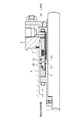
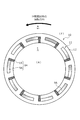
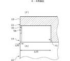
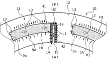
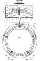
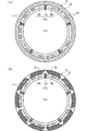
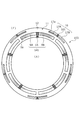
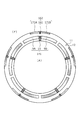
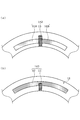
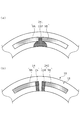
- FIG. 1 It is a longitudinal cross-sectional view showing an example of a mechanical seal in Embodiment 1 of the present invention. It is the figure which looked at the sliding surface of the stationary seal ring from the direction of an axis. It is an AA sectional view. It is a principal part enlarged view in the sliding surface of a stationary seal ring.
- (A) ⁇ (c) is a schematic diagram for explaining the operation of the sealed liquid sucked from the inner diameter side of the liquid guide groove portion at the initial stage of relative rotation to flow out between the sliding surfaces. It is the figure which looked at the sliding surface of the stationary seal ring in Example 2 of the present invention from the direction of an axis.
- (A) is explanatory drawing which shows the modification 3 of this invention
- (b) is explanatory drawing which shows the modification 4 of this invention.
- (A) is explanatory drawing which shows the modification 5 of this invention
- (b) is explanatory drawing which shows the modification 6 of this invention.
- (A) is explanatory drawing which shows the modification 7 of this invention
- (b) is explanatory drawing which shows the modification 8 of this invention.
- (A) is explanatory drawing which shows the modification 9 of this invention
- (b) is explanatory drawing which shows the modification 10 of this invention.
- (A) is explanatory drawing which shows the modification 11 of this invention
- (b) is explanatory drawing which shows the modification 12 of this invention.
- the sliding component according to the first embodiment will be described with reference to FIGS. 1 to 5.
- description will be given by taking an example in which the sliding component is a mechanical seal.
- the outer diameter side of the sliding component constituting the mechanical seal will be described as the sealed liquid side (high pressure side) as the sealed fluid side, and the inner diameter side as the atmosphere side (low pressure side) as the leakage side.
- dots may be attached to grooves or the like formed on the sliding surface in the drawings.
- the mechanical seal for a general industrial machine shown in FIG. 1 is an inside type that seals the sealed liquid F that is about to leak from the outer diameter side of the sliding surface toward the inner diameter side.
- a rotary sealing ring 20 which is an annular sliding component provided rotatably with the rotary shaft 1 via a sleeve 2 and a seal cover 5 fixed to a housing 4 of a device to be mounted are in a non-rotating state and a shaft.
- a ring-shaped stationary seal ring 10 as a sliding component provided in a directionally movable state.
- the stationary seal ring 10 is axially urged by a bellows 7 so that the stationary seal ring 10 is urged in the axial direction.
- the sliding surface 11 of 10 and the sliding surface 21 of the rotary seal ring 20 are adapted to slide in close contact with each other.
- the sliding surface 21 of the rotary seal ring 20 is a flat surface, and no recess is provided on this flat surface.
- the stationary seal ring 10 and the rotary seal ring 20 are typically formed of SiC (hard material) or a combination of SiC (hard material) and carbon (soft material), but the sliding material is not limited to this. Any material used as a sliding material for a mechanical seal can be applied.
- the SiC includes, for example, a sintered body using boron, aluminum, carbon or the like as a sintering aid, and a material composed of two or more kinds of phases having different components and compositions, for example, SiC in which graphite particles are dispersed, or SiC. There are reaction-sintered SiC, SiC-TiC, SiC-TiN, etc.
- a metal material, a resin material, a surface modifying material (coating material), a composite material, or the like can be applied.
- the rotary seal ring 20 slides relative to the stationary seal ring 10 as indicated by the arrow, and a plurality of dynamic pressures are applied to the sliding surface 11 of the stationary seal ring 10.
- the generating mechanisms 14 are evenly arranged in the circumferential direction of the stationary seal ring 10. A portion of the sliding surface 11 other than the dynamic pressure generating mechanism 14 is a land 12 forming a flat end surface.
- FIGS. 2 to 4 an outline of the dynamic pressure generating mechanism 14 will be described based on FIGS. 2 to 4.
- the left side of FIG. 4 is the downstream side of the sealed liquid F flowing in the Rayleigh step 9A described later, and the right side of FIG. Will be described as an upstream side of the sealed liquid F flowing in the Rayleigh step 9A.
- the dynamic pressure generating mechanism 14 is concentric with the liquid guide groove portion 15 as a deep groove portion that communicates with the atmosphere side and extends in the outer diameter direction, and the stationary seal ring 10 from the outer diameter side end portion of the liquid guide groove portion 15 toward the downstream side.
- a Rayleigh step 9A as a shallow groove extending in the circumferential direction. That is, the dynamic pressure generation mechanism 14 has an inverted L-shape when the sliding surface 11 is viewed from the direction orthogonal to the liquid guide groove 15 and the Rayleigh step 9A.
- the liquid guide groove 15 of the first embodiment extends in the radial direction so as to be orthogonal to the axis of the stationary seal ring 10. Further, the liquid guide groove portion 15 and the Rayleigh step 9A communicate with each other, and a step 18 in the depth direction is formed in the communicating portion.
- the Rayleigh step 9A has a wall portion 9a formed at the end portion on the downstream side and orthogonal to the rotation direction.
- the wall portion 9a is not limited to be orthogonal to the rotation direction, and may be inclined with respect to the rotation direction or may be formed in a step shape.
- the depth dimension L10 of the liquid guide groove portion 15 is deeper than the depth dimension L20 of the Rayleigh step 9A (L10>L20).
- the depth dimension L10 of the liquid guide groove portion 15 in the first embodiment is 100 ⁇ m
- the depth dimension L20 of the Rayleigh step 9A is 5 ⁇ m. That is, a step 18 in the depth direction is formed between the liquid guide groove portion 15 and the Rayleigh step 9A by the downstream side surface of the liquid guide groove portion 15 and the bottom surface of the Rayleigh step 9A. If the depth of the liquid guide groove 15 is deeper than that of the Rayleigh step 9A, the depth of the liquid guide groove 15 and the Rayleigh step 9A can be freely changed. It is more than 5 times the dimension L20.
- the bottom surface of the Rayleigh step 9A has a flat surface and is formed parallel to the land 12, but it does not hinder the formation of a minute concave portion on the flat surface or an inclination with respect to the land 12. Further, the two arcuate surfaces extending in the circumferential direction of the Rayleigh step 9A are orthogonal to the bottom surface of the Rayleigh step 9A. Further, although the bottom surface of the liquid guide groove portion 15 has a flat surface and is formed in parallel with the land 12, it does not prevent formation of a fine recessed portion on the flat surface or an inclination with respect to the land 12. Further, the two planes extending in the radial direction of the liquid guide groove portion 15 are orthogonal to the bottom surface of the liquid guide groove portion 15, respectively.
- the rotary seal ring 20 rotates relative to the stationary seal ring 10 (see the black arrow in FIG. 2). 4, the low pressure side fluid A on the atmosphere side is introduced from the liquid guide groove portion 15 as shown by the arrow L1, and the low pressure side fluid A is moved in the rotation direction of the rotary seal ring 20 by the Rayleigh step 9A. As shown in (4), the dynamic pressure is generated in the Rayleigh step 9A because it follows the movement.
- the pressure becomes highest in the vicinity of the wall 9a, which is the downstream end of the Rayleigh step 9A, and the low-pressure side fluid A flows out from the vicinity of the wall 9a to its periphery as shown by arrow L3.
- the pressure gradually decreases toward the upstream side of the Rayleigh step 9A.
- the high-pressure sealed liquid F constantly flows between the sliding surfaces 11 and 21 from their outer diameter side, so that so-called fluid lubrication is performed. It has become.
- the sealed liquid F near the Rayleigh step 9A has a high pressure especially on the downstream side of the Rayleigh step 9A as described above, the sealed liquid F remains positioned on the land 12 as shown by the arrow H1. Almost never enters 9A.
- the sealed liquid F near the liquid guide groove portion 15 enters the liquid guide groove portion 15 as shown by an arrow H2 because the liquid guide groove portion 15 is a deep groove portion and communicates with the low pressure side. It's getting easier.
- the sealed liquid F is a liquid and has a large surface tension, it is easy to move along the side wall surface of the liquid guide groove 15 and enter the liquid guide groove 15.
- the rotary seal ring 20 rotates relative to the stationary seal ring 10 (see the black arrow in FIG. 2), as shown in FIG.
- the sealed liquid F that has entered the liquid guide groove portion 15 becomes lumpy droplets, as indicated by the symbol H3.
- the droplet has a certain volume, it is drawn into the Rayleigh step 9A by the relatively low pressure formed on the upstream side of the Rayleigh step 9A, as indicated by the symbol H4. Be done.
- the sealed liquid F newly enters the liquid guide groove portion 15 and becomes a droplet H3'. At this time, more liquid to be sealed F enters the liquid guide groove 15 than in the initial state of relative rotation in FIG.
- the sealed liquid F drawn into the Rayleigh step 9A receives a large shearing force from the rotary sealing ring 20, and moves to the downstream side in the Rayleigh step 9A while the pressure is increased. Then, as shown by the arrow H5, it flows out near the wall 9a. At the same time, a large amount of the sealed liquid F newly enters the liquid guide groove portion 15 to become a droplet H3′′, and the droplet H3′ is drawn into the Rayleigh step 9A as indicated by the symbol H4′.
- the amount of the sealed liquid F that enters the liquid guide groove portion 15 is larger than that in the state shown in FIG. 5C, and the sealed liquid F continuously flows out from the Rayleigh step 9A between the sliding surfaces 11 and 21. It will be in a steady state.
- the high-pressure sealed liquid F constantly flows between the sliding surfaces 11 and 21 from the outer diameter side of the sliding surfaces 11 and 21 and the fluid lubrication is performed as described above.
- it is a transient short time until it becomes a steady state through FIGS. 5(a), 5(b) and 5(c).
- the amount of the sealed liquid F remaining in the dynamic pressure generation mechanism 14 causes The operation starts from any one of the state, the state of FIG. 5B, the state of FIG. 5C, and the steady state.
- the liquid guide groove portion 15 is a deep groove portion and communicates with the low pressure side, the sealed liquid F indicated by the arrow H5 is easily drawn into the adjacent liquid guide groove portion 15, and the sliding The amount of the sealed liquid F between the moving surfaces 11 and 21 is stable, and high lubricity can be maintained. Further, since the interfacial tension of a liquid is larger than that of a gas, the sealed liquid F is easily held between the sliding surfaces 11 and 21, and the atmosphere is closer to the inner diameter side than the stationary seal ring 10 and the rotary seal ring 20. Easily discharged.
- the Rayleigh step 9A draws in the sealed liquid F that has entered the liquid guide groove 15 to generate a dynamic pressure. Since the liquid guide groove portion 15 has a deep groove and a large volume, even if the sealed liquid F is supplied to the low pressure side of the sliding surface 11, the sealed liquid F is recovered and the sliding surface 11 is subjected to the Rayleigh step 9A. , 21 between them, the lubricity can be improved in a large area of the sliding surface 11. Further, since the sealed liquid F is recovered by the liquid guide groove portion 15 communicating with the low pressure side on the inner diameter side of the sliding surfaces 11 and 21, the sealed liquid F leaking to the low pressure side is small.
- the sealed liquid F drawn into the Rayleigh step 9A can be secured and the sealed liquid F held in the liquid guide groove portion 15 can be secured. Even if the amount of the sealed liquid F increases/decreases in a short time, the amount of the sealed liquid F drawn into the Rayleigh step 9A can be made substantially constant, and the sliding surfaces 11 and 21 can be prevented from being poorly lubricated. .. Further, since the liquid guide groove portion 15 communicates with the low pressure side, the pressure in the liquid guide groove portion 15 is lower than the pressure of the sealed liquid F between the sliding surfaces 11 and 21, and the liquid guide groove portion 15 has The sealed liquid F in the vicinity is easily drawn into the liquid guide groove 15.
- the liquid guide groove 15 extends in the radial direction. Specifically, the liquid guide groove portion 15 extends in a direction orthogonal to the central axis of the stationary seal ring 10, and is arranged in the circumferential direction so that the Rayleigh step 9A intersects from the outer diameter side end portion thereof. The influence of the dynamic pressure and the inertia of the flow of the sealed liquid F generated in the Rayleigh step 9A is reduced. Therefore, the sealed liquid F or the low-pressure side fluid A attached to the inner surface of the stationary seal ring 10 is less likely to be directly sucked into the Rayleigh step 9A from the inner diameter side of the liquid guide groove portion 15. Further, the sealed liquid F can be held in the liquid guide groove 15 without being directly affected by the dynamic pressure.
- the circumferential width of the liquid guide groove portion 15 can be shortened and a large number can be arranged in the circumferential direction of the stationary seal ring 10, the degree of freedom in design is high.
- the liquid guide groove 15 is not limited to the direction orthogonal to the central axis of the stationary seal ring 10, and may be inclined from the position orthogonal to the central axis of the stationary seal ring 10, but the inclination is less than 45 degrees. Is preferred. Further, the shape of the liquid guide groove 15 can be freely changed such as an arc shape.
- the step 18 is formed by the downstream side surface of the liquid guide groove portion 15 and the bottom surface of the Rayleigh step 9A, the influence of the dynamic pressure is directly exerted.
- the sealed liquid F can be held in the liquid guide groove portion 15 without receiving it.
- the Rayleigh step 9A communicates with the liquid guide groove portion 15 over the entire width in the radial direction, an opening area for the liquid guide groove portion 15 of the Rayleigh step 9A can be secured, and the object held by the liquid guide groove portion 15 can be secured.
- the sealed liquid F can be efficiently sucked up.
- the liquid guide groove 15 communicates with the inner diameter side of the stationary seal ring 10. That is, the sliding component is an inside mechanical seal, and when the stationary seal ring 10 and the rotary seal ring 20 are relatively rotated, the sealed liquid F in the Rayleigh step 9A can be returned to the high pressure side by centrifugal force. The leakage of the sealed liquid F to the low pressure side on the inner diameter side of the sliding surfaces 11 and 21 can be reduced.
- the stationary seal ring 10 is provided with the dynamic pressure generating mechanism 14, it is easy to keep the inside of the liquid guide groove 15 close to the atmospheric pressure when the stationary seal ring 10 and the rotary seal ring 20 are relatively rotated.
- the liquid guide groove 15 and the Rayleigh step 9A have an inverted L-shape when viewed from the direction orthogonal to the sliding surface 11, but the liquid guide groove 15 is, for example.
- the Rayleigh step 9A may be communicated smoothly without intersecting each other, for example, in a straight line shape or an arc shape.
- the step 18 may not be provided in the communication portion between the liquid guide groove portion 15 and the Rayleigh step 9A, and for example, the liquid guide groove portion 15 and the Rayleigh step 9A may communicate with each other through an inclined surface.
- a portion having a depth dimension of 5 ⁇ m or less can be the Rayleigh step 9A as the shallow groove portion, and a portion deeper than 5 ⁇ m can be the liquid guide groove portion 15 as the deep groove portion.
- the shallow groove is not limited to the shape that extends in the circumferential direction concentrically with the stationary seal ring, but may be formed in an arc shape so that the downstream end faces the high pressure side, for example. Further, the shallow groove portion may be linearly extended from the deep groove portion, or may be meanderingly extended.
- the dynamic pressure generating mechanism 141 provided in the stationary sealing ring 101 is stationary from the liquid guide groove portion 15, the Rayleigh step 9A, and the outer diameter side end portion of the liquid guide groove portion 15 toward the downstream side.
- a reverse Rayleigh step 9B as a shallow groove portion that extends in the circumferential direction concentrically with the sealing ring 101. That is, the dynamic pressure generating mechanism 141 has a T-shape when the sliding surface 11 is viewed in a direction orthogonal to each other.
- the reverse Rayleigh step 9B is formed with the same depth of 5 ⁇ m as the Rayleigh step 9A.
- the low-pressure side fluid A moves in the order of arrows L1, L2, and L3 to generate dynamic pressure in the Rayleigh step 9A.
- the low-pressure side fluid A moves in the order of arrows L1, L2′, L3′ to generate dynamic pressure in the reverse Rayleigh step 9B. Occurs. That is, when the rotary seal ring 20 rotates clockwise in the plane of FIG. 6, the reverse Rayleigh step 9B functions as a Rayleigh step and the Rayleigh step 9A functions as a reverse Rayleigh step.
- the Rayleigh step 9A and the reverse Rayleigh step 9B are extended from the liquid guide groove portion 15 to both sides in the circumferential direction, and either one of the Rayleigh step 9A and the reverse Rayleigh step 9B is used as a shallow groove portion for generating a dynamic pressure. Therefore, it can be used regardless of the relative rotation direction of the stationary seal ring 101 and the rotary seal ring 20.
- the Rayleigh step 9A in the dynamic pressure generating mechanism 141 is circumferentially adjacent to the reverse Rayleigh step 9B of the adjacent dynamic pressure generating mechanism 141'. According to this, the sealed liquid F flowing out from the vicinity of the wall portion 9a of the Rayleigh step 9A in the dynamic pressure generating mechanism 141 and moving toward the inner diameter side is sucked from the reverse Rayleigh step 9B in the adjacent dynamic pressure generating mechanism 141'. Therefore, the leakage of the sealed liquid F to the low pressure side can be reduced.
- the case where the Rayleigh step 9A and the reverse Rayleigh step 9B have the same depth dimension is illustrated, but they may be formed with different depth dimensions. Further, the two may have the same or different circumferential length and radial width.
- the Rayleigh step 9A of the dynamic pressure generating mechanism 141 and the reverse Rayleigh step 9B of the adjacent dynamic pressure generating mechanism 141′ are spaced apart by a long distance in the circumferential direction to further increase the pressure for separating the sliding surfaces 11, 21. You may
- the specific dynamic pressure generating mechanism 16 includes a liquid guide groove portion 161 that communicates with the high pressure side, and a Rayleigh step 17A that extends in the circumferential direction concentrically with the stationary seal ring 102 from the inner diameter side end portion of the liquid guide groove portion 161 toward the downstream side. And a reverse Rayleigh step 17B that extends in the circumferential direction concentrically with the stationary seal ring 102 from the inner diameter side end of the liquid guide groove 161 toward the upstream side.
- the liquid guide groove 161 and the liquid guide groove 15 are formed at positions corresponding to the circumferential direction. Further, the liquid guide groove portion 161 functions as a deep groove portion of the specific dynamic pressure generating mechanism 16, and the Rayleigh step 17A and the reverse Rayleigh step 17B function as a shallow groove portion of the specific dynamic pressure generating mechanism 16.
- the Rayleigh step 9A and the reverse Rayleigh step 9B of the dynamic pressure generating mechanism 141 are formed longer in the circumferential direction than the Rayleigh step 17A and the reverse Rayleigh step 17B of the specific dynamic pressure generating mechanism 16.
- the depth dimension of the Rayleigh step 17A and the reverse Rayleigh step 17B is 5 ⁇ m, which is the same as that of the Rayleigh step 9A and the reverse Rayleigh step 9B.
- the radial widths of the Rayleigh step 17A and the reverse Rayleigh step 17B are smaller than the radial widths of the Rayleigh step 9A and the reverse Rayleigh step 9B. That is, the volume of the dynamic pressure generating mechanism 141 is larger than the volume of the specific dynamic pressure generating mechanism 16.
- the sealed liquid F moves in the order of arrows L11, L12, and L13, and a dynamic pressure is generated in the Rayleigh step 17A.
- the rotary sealing ring 20 rotates clockwise in the plane of the paper indicated by the dotted arrow in FIG. 7, the liquid F to be sealed moves in the order of arrows L11, L12′, and L13′ to generate dynamic pressure in the reverse Rayleigh step 17B. Occurs.
- the dynamic pressure can be generated in the specific dynamic pressure generating mechanism 16 regardless of the relative rotation direction between the stationary seal ring 102 and the rotary seal ring 20.
- the sealed liquid F that tends to leak from the sliding surface 11 to the low pressure side while separating the sliding surfaces 11 and 21 by the dynamic pressure generated by the specific dynamic pressure generating mechanism 16 to generate an appropriate liquid film. Can be collected by the dynamic pressure generation mechanism 141.
- the suction force of the Rayleigh step 9A and the reverse Rayleigh step 9B of the dynamic pressure generation mechanism 141 is increased to reduce the dynamic pressure on the low pressure side.
- the dynamic pressure balance between the generation mechanism 141 and the specific dynamic pressure generation mechanism 16 on the high pressure side can be adjusted.
- the circumferential lengths of the Rayleigh step 9A and the reverse Rayleigh step 9B may be the same as those of the Rayleigh step 17A and the reverse Rayleigh step 17B, or may be shorter than those of the Rayleigh step 17A and the reverse Rayleigh step 17B. Further, the Rayleigh step 17A and the reverse Rayleigh step 17B may be formed to have different depth dimensions from those of the Rayleigh step 9A and the reverse Rayleigh step 9B. The radial widths of the Rayleigh step 17A and the reverse Rayleigh step 17B may be formed to be larger than the radial widths of the Rayleigh step 9A and the reverse Rayleigh step 9B. It is preferable that the volume of the dynamic pressure generating mechanism 141 be larger than the volume of the specific dynamic pressure generating mechanism 16.
- the specific dynamic pressure generating mechanism of the modified example 1 is a dimple 30 having a circular shape and having a circular shape when the sliding surface 11 is viewed in a direction orthogonal to each other.
- the shape, quantity, arrangement, etc. of the dimples 30 can be freely changed.
- the specific dynamic pressure generating mechanism of Modification 2 is arc grooves 31 and 32 extending in an arc shape while inclining in the radial direction.
- the outer diameter side ends of the circular arc grooves 31 and 32 communicate with the high pressure side, and a plurality of circular arc grooves 31 are arranged on the outer diameter side of the Rayleigh step 9A.
- a plurality of reverse Rayleigh steps 9B are provided on the outer diameter side.
- the circular arc groove 31 has a shape in which the sealed liquid F moves toward the inner diameter side when the rotary seal ring 20 rotates counterclockwise in FIG. 8B, and the circular arc groove 32 is When the rotary seal ring 20 rotates clockwise in the plane of FIG. 8B, the sealed liquid F moves toward the inner diameter side.
- the pressure on the inner diameter side of the circular arc groove 31 increases, and when it rotates clockwise, the pressure on the inner diameter side of the circular arc groove 32 increases, so that the sliding surfaces 11, 21 are An appropriate liquid film can be generated by separating them.
- the shape, quantity, arrangement, etc. of the arcuate grooves 31, 32 can be freely changed.
- the stationary seal ring 103 is arranged so as to be displaced from the dynamic pressure generating mechanism 141 in the circumferential direction so that the specific dynamic pressure generating mechanism 16 is located between the adjacent dynamic pressure generating mechanisms 141.
- the specific dynamic pressure generating mechanism 16 is radially overlapped with the adjacent dynamic pressure generating mechanism 141.
- the sealed liquid F flowing out from the downstream end of the Rayleigh step 17A of the specific dynamic pressure generating mechanism 16 is drawn into the reverse Rayleigh step 9B of the dynamic pressure generating mechanism 141, and the Rayleigh step of the dynamic pressure generating mechanism 141. Since the sealed liquid F flowing out from the downstream side of 9A is drawn into the reverse Rayleigh step 17B of the specific dynamic pressure generating mechanism 16 and circulates, a liquid film can be stably formed between the sliding surfaces 11 and 21. it can.
- the wall portion 9a that is the end of the dynamic pressure generating mechanism 141 and the wall portion 17a that is the end of the specific dynamic pressure generating mechanism 16 are displaced in the circumferential direction, pressure is applied in the circumferential direction of the sliding surfaces 11 and 21. Can be dispersed and is well balanced. Further, the sealed liquid F flowing out from the downstream end of the Rayleigh step 17A of the specific dynamic pressure generating mechanism 16 can be efficiently collected in the liquid guide groove 15 of the dynamic pressure generating mechanism 141.
- the Rayleigh step 171A and the reverse Rayleigh step 171B are formed from the outer diameter side end of the liquid guide groove portion 161, and the Rayleigh step 171A and the reverse Rayleigh step 171B are It communicates with the high voltage side.
- the mechanical seal shown in FIG. 11 is an outside type that seals the sealed liquid F that is about to leak from the inner diameter side of the sliding surface toward the outer diameter side.
- the dynamic pressure generating mechanism 141 is arranged on the outer diameter side so as to communicate with the low pressure side
- the specific dynamic pressure generating mechanism 16 is arranged on the inner diameter side so as to communicate with the high pressure side.
- the dynamic pressure generating mechanism may be formed in an inverted L-shape or an L-shape corresponding to one rotation as in the first embodiment, which will be described later.
- a modified example of the dynamic pressure generation mechanism may be applied.
- the specific dynamic pressure generating mechanism may not be provided as in the first embodiment, or the specific dynamic pressure generating mechanism may be formed as shown in FIGS. 8 to 10.
- the Rayleigh step 91A and the reverse Rayleigh step 91B are extended in the circumferential direction from the radial center portion of the liquid guide groove portion 15. According to this, since the liquid guide groove portion 15 extends to the outer diameter side from the Rayleigh step 91A and the reverse Rayleigh step 91B, the sealed liquid F on the outer diameter side easily enters the liquid guide groove portion 15 and the liquid guide groove portion is formed. A large amount of the sealed liquid F can be stored in 15.
- the groove 92 as a shallow groove portion that shifts to the outer diameter side of the liquid guide groove portion 15 as a deep groove portion and extends in the circumferential direction is provided. It is formed in an arc shape and has a T-shape when the sliding surface 11 is viewed in a direction orthogonal to each other.
- the sealed liquid F can be directly supplied from the reverse Rayleigh step, which is a portion of the groove 92 upstream of the liquid guide groove portion 15, to the Rayleigh step, which is a portion downstream of the liquid guide groove portion 15. If the shallow groove portion and the deep groove portion communicate with each other, the position of the shallow groove portion in the deep groove portion can be freely changed.
- the liquid guide groove portion 151 in the dynamic pressure generating mechanism 144 of the modified example 5 is arranged in the circumferential direction of the outer diameter side end portion 151a communicating with the Rayleigh step 9A and the reverse Rayleigh step 9B.
- the width is smaller than the inner diameter side end 151b. According to this, since the inner diameter side end portion 151b is formed wider than the outer diameter side end portion 151a in the circumferential direction, the sealed liquid F adhering to the inner side surface rather than the sliding surface 11 is guided to the liquid guiding groove portion 151. Easy to inhale.
- the depth dimension of the inner diameter side end portion 152b is the depth dimension of the outer diameter side end portion 152a. Formed deeper than. According to this, since a step is formed in the communicating portion between the inner diameter side end portion 152b and the outer diameter side end portion 152a, the sealed liquid F held in the inner diameter side end portion 152b is unlikely to flow out to the low pressure side. Has become.
- the liquid guide groove portion 153 in the dynamic pressure generating mechanism 146 of the modified example 7 has a first portion 153b located on the inner diameter side of the Rayleigh step 9A and the reverse Rayleigh step 9B,
- the second portion 153a is formed to have a smaller width in the circumferential direction than the first portion 153b and extends to the outer diameter side of the first portion 153b.
- the Rayleigh step 9A and the reverse Rayleigh step 9B communicate with the outer diameter side end of the second portion 153a, and are arranged apart from the first portion 153b on the outer diameter side.
- the second portion 154a communicating with the Rayleigh step 9A and the reverse Rayleigh step 9B is located on the inner diameter side.
- the width is larger in the circumferential direction than the first portion 154b.
- the first portion 154b and the Rayleigh step 9A and the reverse Rayleigh step 9B have the same width in the radial direction and communicate with each other over the entire width. According to this, since the width of the first portion 154b is narrower than that of the second portion 154a, it is difficult for the sealed liquid F held in the second portion 154a on the outer diameter side to flow out to the low pressure side. ing.
- the portion communicating with the Rayleigh step 9A and the reverse Rayleigh step 9B is tapered toward the outer diameter side. ing. Thereby, the sealed liquid F can be guided to the outer diameter side of the liquid guide groove 155.
- the portion on the inner diameter side of the Rayleigh step 9A and the reverse Rayleigh step 9B is tapered toward the inner diameter side. doing. According to this, the sealed liquid F held in the liquid guide groove 156 is unlikely to flow out to the low pressure side.
- the portion on the inner diameter side of the Rayleigh step 9A and the reverse Rayleigh step 9B has an arc shape. It is formed so as to swell in the circumferential direction more than the portion communicating with the Rayleigh step 9A and the reverse Rayleigh step 9B. Since the inner diameter side portion of the liquid guide groove portion 157 is a curved surface, the sealed liquid F can smoothly flow.
- the dynamic pressure generating mechanism 14 and the dynamic pressure generating mechanism 242 are alternately arranged in the circumferential direction.
- the dynamic pressure generating mechanism 242 includes a liquid guide groove portion 158 and a reverse Rayleigh step 9B circumferentially extending from the outer diameter side end portion of the liquid guide groove portion 158 to the downstream side. That is, the dynamic pressure generating mechanism 242 has an L shape when the sliding surface 11 is viewed in a direction orthogonal to each other. According to this, it can be used regardless of the rotation direction of the rotary seal ring 20.
- the mechanical seal for general industrial machines has been described as an example of the sliding component, but other mechanical seals for automobiles, water pumps, etc. may be used. Further, it is not limited to the mechanical seal, and sliding parts other than the mechanical seal such as a slide bearing may be used.
- the dynamic pressure generating mechanism may be provided only in the stationary seal ring 20, and in both the static seal ring and the rotary seal ring. It may be provided.
- the sliding parts are provided with a plurality of dynamic pressure generating mechanisms having the same shape, but a plurality of dynamic pressure generating mechanisms having different shapes may be provided. Further, the interval and the number of the dynamic pressure generating mechanism can be changed appropriately.
- the sealed fluid side has been described as the high pressure side and the leak side as the low pressure side, the sealed fluid side may be the low pressure side and the leak side may be the high pressure side, and the sealed fluid side and the leak side are substantially the same. It may be the same pressure.
Landscapes
- Engineering & Computer Science (AREA)
- General Engineering & Computer Science (AREA)
- Mechanical Engineering (AREA)
- Chemical & Material Sciences (AREA)
- Oil, Petroleum & Natural Gas (AREA)
- Physics & Mathematics (AREA)
- Fluid Mechanics (AREA)
- Mechanical Sealing (AREA)
- Sliding-Contact Bearings (AREA)
Abstract
Description
回転機械の相対回転する箇所に配置される環状の摺動部品であって、
前記摺動部品の摺動面には、漏れ側に連通する深溝部と、該深溝部に連通して周方向に延設される浅溝部と、から構成される動圧発生機構が複数設けられている。
これによれば、深溝部は溝の深さが深く容積が大きいので、摺動面の漏れ側まで供給された多くの量の被密封流体を回収して浅溝部から被密封流体を摺動面間に流出させるので、摺動面の広い面積で潤滑性を向上させることができる。また、漏れ側に連通する深溝部によって被密封流体を回収し、回収した被密封流体を浅溝部から摺動面間に流出させて一部を径方向被密封流体側に戻すので、漏れ側に漏れる被密封流体が少ない。
これによれば、動圧の影響を受けずに被密封流体を深溝部に保持できる。
これによれば、動圧の影響を受けずに被密封流体を深溝部に保持できる。
これによれば、深溝部の周方向のいずれか一方に配置される浅溝部を動圧発生用の浅溝部として利用できるため、摺動部品の相対回転方向に限られず使用できる。
これによれば、摺動部品の相対回転時に、動圧発生機構における一方の浅溝部から摺動面間に供給され漏れ側に移動しようとする被密封流体を隣接する動圧発生機構における他方の浅溝部により回収できる。
これによれば、浅溝部から摺動面間に供給された被密封流体を遠心力により被密封流体側に戻すことができるとともに、遠心力により深溝部内に被密封流体を保持しやすい。
これによれば、摺動部品の相対回転時に、特定動圧発生機構により摺動面間を離間させて摺動面間に適当な流体膜を生成しつつ、動圧発生機構によって被密封流体の漏れ側への漏れを低減できる。
9B 逆レイリーステップ(浅溝部)
10 静止密封環(摺動部品)
11 摺動面
14 動圧発生機構
15 液体誘導溝部(深溝部)
16 特定動圧発生機構
17A レイリーステップ(浅溝部)
17B 逆レイリーステップ(浅溝部)
18 段差
20 回転密封環(摺動部品)
21 摺動面
141 動圧発生機構
Claims (7)
- 回転機械の相対回転する箇所に配置される環状の摺動部品であって、
前記摺動部品の摺動面には、漏れ側に連通する深溝部と、該深溝部に連通して周方向に延設される浅溝部と、から構成される動圧発生機構が複数設けられている摺動部品。 - 前記深溝部が径方向に延びている請求項1に記載の摺動部品。
- 前記浅溝部と前記深溝部との連通部分には、深さ方向の段差が形成されている請求項1または2に記載の摺動部品。
- 前記浅溝部は、前記深溝部から周方向両側に延びている請求項1ないし3のいずれかに記載の摺動部品。
- 前記動圧発生機構における一方の浅溝部は、隣接する前記動圧発生機構における他方の浅溝部と周方向に隣接する請求項4に記載の摺動部品。
- 前記深溝部は内径側に連通する請求項1ないし5のいずれかに記載の摺動部品。
- 前記摺動部品の摺動面には、前記動圧発生機構よりも被密封流体側に配置され前記動圧発生機構とは独立する特定動圧発生機構を備えている請求項1ないし6のいずれかに記載の摺動部品。
Priority Applications (8)
| Application Number | Priority Date | Filing Date | Title |
|---|---|---|---|
| KR1020217025490A KR102647265B1 (ko) | 2019-02-04 | 2020-01-31 | 슬라이딩 부품 |
| CN202080010580.6A CN113330224A (zh) | 2019-02-04 | 2020-01-31 | 滑动部件 |
| US17/424,850 US12259043B2 (en) | 2019-02-04 | 2020-01-31 | Sliding component |
| CN202211560829.8A CN115853894A (zh) | 2019-02-04 | 2020-01-31 | 滑动部件 |
| EP20753172.4A EP3922876B1 (en) | 2019-02-04 | 2020-01-31 | Sliding component |
| JP2020571157A JP7313788B2 (ja) | 2019-02-04 | 2020-01-31 | 摺動部品 |
| KR1020237005133A KR102655679B1 (ko) | 2019-02-04 | 2020-01-31 | 슬라이딩 부품 |
| JP2023105640A JP7538920B2 (ja) | 2019-02-04 | 2023-06-28 | 摺動部品 |
Applications Claiming Priority (2)
| Application Number | Priority Date | Filing Date | Title |
|---|---|---|---|
| JP2019-017872 | 2019-02-04 | ||
| JP2019017872 | 2019-02-04 |
Publications (1)
| Publication Number | Publication Date |
|---|---|
| WO2020162348A1 true WO2020162348A1 (ja) | 2020-08-13 |
Family
ID=71947970
Family Applications (1)
| Application Number | Title | Priority Date | Filing Date |
|---|---|---|---|
| PCT/JP2020/003643 Ceased WO2020162348A1 (ja) | 2019-02-04 | 2020-01-31 | 摺動部品 |
Country Status (6)
| Country | Link |
|---|---|
| US (1) | US12259043B2 (ja) |
| EP (1) | EP3922876B1 (ja) |
| JP (2) | JP7313788B2 (ja) |
| KR (2) | KR102655679B1 (ja) |
| CN (2) | CN115853894A (ja) |
| WO (1) | WO2020162348A1 (ja) |
Cited By (8)
| Publication number | Priority date | Publication date | Assignee | Title |
|---|---|---|---|---|
| JPWO2021193743A1 (ja) * | 2020-03-26 | 2021-09-30 | ||
| JPWO2022230460A1 (ja) * | 2021-04-28 | 2022-11-03 | ||
| WO2023027002A1 (ja) * | 2021-08-25 | 2023-03-02 | イーグル工業株式会社 | 摺動部品 |
| JPWO2023182056A1 (ja) * | 2022-03-24 | 2023-09-28 | ||
| JPWO2023223914A1 (ja) * | 2022-05-19 | 2023-11-23 | ||
| US12110968B2 (en) | 2020-03-09 | 2024-10-08 | Eagle Industry Co., Ltd. | Sliding component |
| WO2025052988A1 (ja) * | 2023-09-05 | 2025-03-13 | イーグル工業株式会社 | 摺動部品 |
| US12590604B2 (en) | 2021-08-25 | 2026-03-31 | Eagle Industry Co., Ltd. | Sliding component |
Families Citing this family (2)
| Publication number | Priority date | Publication date | Assignee | Title |
|---|---|---|---|---|
| EP4411182A4 (en) * | 2021-09-28 | 2025-09-17 | Eagle Ind Co Ltd | SLIDING COMPONENT |
| CN119301388A (zh) | 2022-06-07 | 2025-01-10 | 伊格尔工业股份有限公司 | 滑动部件 |
Citations (6)
| Publication number | Priority date | Publication date | Assignee | Title |
|---|---|---|---|---|
| JP2012002295A (ja) * | 2010-06-17 | 2012-01-05 | Canon Machinery Inc | 平面摺動機構 |
| WO2012046749A1 (ja) | 2010-10-06 | 2012-04-12 | イーグル工業株式会社 | 摺動部品 |
| WO2016167262A1 (ja) * | 2015-04-15 | 2016-10-20 | イーグル工業株式会社 | 摺動部品 |
| WO2016203878A1 (ja) * | 2015-06-15 | 2016-12-22 | イーグル工業株式会社 | 摺動部品 |
| WO2018092742A1 (ja) * | 2016-11-16 | 2018-05-24 | イーグル工業株式会社 | しゅう動部品 |
| WO2018105505A1 (ja) * | 2016-12-07 | 2018-06-14 | イーグル工業株式会社 | しゅう動部品 |
Family Cites Families (173)
| Publication number | Priority date | Publication date | Assignee | Title |
|---|---|---|---|---|
| US3383116A (en) | 1964-09-30 | 1968-05-14 | J C Carter Company | Face seal |
| FR1505487A (fr) | 1966-10-28 | 1967-12-15 | Guinard Pompes | Perfectionnement aux joints tournants à régulation de fuite |
| US3695789A (en) | 1970-04-13 | 1972-10-03 | Case Co J I | Balancing mechanism for fluid translating device |
| US3704019A (en) | 1970-06-19 | 1972-11-28 | Gen Electric | Spiral groove face seals |
| US3675935A (en) | 1970-07-13 | 1972-07-11 | Nasa | Spiral groove seal |
| US3782737A (en) | 1970-07-13 | 1974-01-01 | Nasa | Spiral groove seal |
| NL7213192A (ja) | 1972-09-29 | 1974-04-02 | ||
| US4056478A (en) | 1973-10-04 | 1977-11-01 | Sargent Industries, Inc. | Bearing material employing frangible microcapsules containing lubricant |
| JPS5134974A (en) | 1974-09-19 | 1976-03-25 | Kinugawa Rubber Ind | Dainamitsukushiiru no seiho |
| DE2504204C3 (de) | 1975-02-01 | 1981-11-12 | Skf Kugellagerfabriken Gmbh, 8720 Schweinfurt | Selbstdruckerzeugendes Axialgleitlager |
| FR2342440A1 (fr) | 1976-02-27 | 1977-09-23 | Ca Atomic Energy Ltd | Joint facial pour arbre tournant |
| DE2610045C2 (de) | 1976-03-11 | 1982-06-16 | M.A.N. Maschinenfabrik Augsburg-Nürnberg AG, 4200 Oberhausen | Gasgesperrte Wellendichtung |
| DE2622772C3 (de) | 1976-05-21 | 1980-05-08 | Hoesch Werke Ag, 4600 Dortmund | Einrichtung für den Transport und Wechsel von Walzen an Walzenbearbeitungsmaschinen |
| DE2624849C3 (de) | 1976-06-03 | 1981-12-03 | Skf Kugellagerfabriken Gmbh, 8720 Schweinfurt | Selbstdruckerzeugendes Radialgleitlager |
| JPS5693599U (ja) | 1979-12-21 | 1981-07-25 | ||
| JPS57163770A (en) | 1981-04-01 | 1982-10-08 | Eagle Ind Co Ltd | Mechanical seal |
| DE3223703C2 (de) | 1982-06-25 | 1984-05-30 | M.A.N. Maschinenfabrik Augsburg-Nürnberg AG, 4200 Oberhausen | Gasgesperrte Wellendichtung mit radialem Dichtspalt |
| JPS5960145U (ja) | 1982-10-15 | 1984-04-19 | 株式会社太洋商会 | ロ−ル状連続袋 |
| JPS59195253A (ja) | 1983-04-20 | 1984-11-06 | Canon Inc | 電子写真装置 |
| JPS59195254A (ja) | 1983-04-20 | 1984-11-06 | Fujitsu Ltd | プリンタの露光量調整方法及び装置 |
| CH677266A5 (ja) | 1986-10-28 | 1991-04-30 | Pacific Wietz Gmbh & Co Kg | |
| US5368314A (en) | 1986-10-28 | 1994-11-29 | Pacific Wietz Gmbh & Co. Kg | Contactless pressurizing-gas shaft seal |
| US4889348A (en) | 1987-06-10 | 1989-12-26 | John Crane-Houdaille, Inc. | Spiral groove seal system for high vapor-pressure liquids |
| JPH02136863A (ja) | 1988-11-18 | 1990-05-25 | Toshiba Corp | 画像形成装置の現像剤 |
| DE3839106A1 (de) | 1988-11-18 | 1990-05-23 | Burgmann Dichtungswerk Feodor | Gleitringdichtung |
| JPH06105105B2 (ja) | 1989-03-03 | 1994-12-21 | 日本ピラー工業株式会社 | 端面非接触形メカニカルシール |
| JPH0646071B2 (ja) * | 1989-04-14 | 1994-06-15 | 日本ピラー工業株式会社 | 非接触形メカニカルシール |
| US5066026A (en) | 1990-06-11 | 1991-11-19 | Kaydon Corporation | Gas face seal |
| JPH0660690B2 (ja) * | 1990-06-18 | 1994-08-10 | 日本ピラー工業株式会社 | 動圧非接触形メカニカルシール |
| JPH0756345B2 (ja) | 1990-07-09 | 1995-06-14 | 株式会社荏原製作所 | 非接触端面シール |
| US5071141A (en) | 1990-07-17 | 1991-12-10 | John Crane Inc. | Spiral groove seal arrangement for high vapor-pressure liquids |
| US5224714A (en) | 1990-07-18 | 1993-07-06 | Ebara Corporation | Noncontacting face seal |
| GB9103217D0 (en) | 1991-02-15 | 1991-04-03 | Crane John Uk Ltd | Mechanical face seals |
| JPH07117167B2 (ja) | 1991-05-09 | 1995-12-18 | 日本ピラー工業株式会社 | 非接触形メカニカルシール装置 |
| JP2516301B2 (ja) | 1991-06-13 | 1996-07-24 | インターナショナル・ビジネス・マシーンズ・コーポレイション | テ―プ駆動装置 |
| US5174584A (en) | 1991-07-15 | 1992-12-29 | General Electric Company | Fluid bearing face seal for gas turbine engines |
| JPH0560247A (ja) | 1991-08-26 | 1993-03-09 | Nippon Pillar Packing Co Ltd | 非接触形メカニカルシール |
| JPH0680623B2 (ja) | 1991-09-25 | 1994-10-12 | 北海道電力株式会社 | 電力需給用計器用変成器 |
| US5447316A (en) | 1992-02-06 | 1995-09-05 | Eagle Industry Co., Ltd. | Gas seal |
| JPH05296248A (ja) | 1992-04-21 | 1993-11-09 | Sumitomo Electric Ind Ltd | 摺動部材 |
| JP3517888B2 (ja) | 1992-09-18 | 2004-04-12 | ブラザー工業株式会社 | カラー電子写真画像形成装置 |
| JPH0769020B2 (ja) | 1992-10-07 | 1995-07-26 | 日本ピラー工業株式会社 | メカニカルシール |
| JPH0769021B2 (ja) | 1992-12-11 | 1995-07-26 | 日本ピラー工業株式会社 | 非接触形軸封装置 |
| US5441283A (en) | 1993-08-03 | 1995-08-15 | John Crane Inc. | Non-contacting mechanical face seal |
| CA2170746C (en) | 1993-09-01 | 2005-01-25 | Josef Sedy | Face seal with angled and annular grooves |
| JP2563081B2 (ja) * | 1994-03-22 | 1996-12-11 | 日本ピラー工業株式会社 | 非接触形軸封装置 |
| US5558341A (en) | 1995-01-11 | 1996-09-24 | Stein Seal Company | Seal for sealing an incompressible fluid between a relatively stationary seal and a movable member |
| US5769604A (en) | 1995-05-04 | 1998-06-23 | Eg&G Sealol, Inc. | Face seal device having high angular compliance |
| JP2903458B2 (ja) | 1995-09-29 | 1999-06-07 | 日本ピラー工業株式会社 | 大型缶水循環ポンプ用熱水軸封装置 |
| JPH09292034A (ja) | 1996-04-25 | 1997-11-11 | Mitsubishi Heavy Ind Ltd | メカニカルシール |
| US5833518A (en) | 1996-08-02 | 1998-11-10 | Flowserve Management Company | Method for forming a wavy face ring |
| US5834094A (en) | 1996-09-30 | 1998-11-10 | Surface Technologies Ltd. | Bearing having micropores and design method thereof |
| JPH10281299A (ja) | 1997-04-11 | 1998-10-23 | Mitsubishi Heavy Ind Ltd | メカニカルシール装置 |
| JPH10292867A (ja) | 1997-04-16 | 1998-11-04 | Mitsubishi Heavy Ind Ltd | ガスシール装置 |
| US6152452A (en) | 1997-10-17 | 2000-11-28 | Wang; Yuming | Face seal with spiral grooves |
| CN1133834C (zh) | 1997-11-21 | 2004-01-07 | 日本皮拉工业株式会社 | 静压型非接触气封 |
| WO1999027281A1 (en) | 1997-11-21 | 1999-06-03 | Nippon Pillar Packing Co., Ltd. | Static pressure noncontact gas seal |
| JPH11287329A (ja) | 1998-04-03 | 1999-10-19 | Eagle Ind Co Ltd | 摺動材 |
| US6213473B1 (en) | 1999-03-06 | 2001-04-10 | Utex Industries, Inc. | Double gas seal with coplanar pad faces |
| JP4232278B2 (ja) * | 1999-06-25 | 2009-03-04 | パナソニック株式会社 | 動圧軸受及びそれを搭載したスピンドルモータ |
| JP3066367U (ja) | 1999-08-05 | 2000-02-18 | 第一精工株式会社 | 遊漁用容器と付属部材 |
| US7044470B2 (en) | 2000-07-12 | 2006-05-16 | Perkinelmer, Inc. | Rotary face seal assembly |
| US6446976B1 (en) | 2000-09-06 | 2002-09-10 | Flowserve Management Company | Hydrodynamic face seal with grooved sealing dam for zero-leakage |
| CN2460801Y (zh) | 2001-01-18 | 2001-11-21 | 王玉明 | 可双向旋转的螺旋槽端面密封装置 |
| US6454268B1 (en) | 2001-02-09 | 2002-09-24 | Eagle Industry Co., Ltd. | Shaft seal device |
| US6655693B2 (en) | 2001-04-26 | 2003-12-02 | John Crane Inc. | Non-contacting gas compressor seal |
| US6692006B2 (en) | 2001-10-15 | 2004-02-17 | Stein Seal Company | High-pressure film-riding seals for rotating shafts |
| JP4054608B2 (ja) | 2002-05-23 | 2008-02-27 | イーグル工業株式会社 | 板ブラシシール |
| CN100427816C (zh) | 2002-09-20 | 2008-10-22 | 徐万福 | 一种由角形微槽族组成的螺旋槽端面机械密封 |
| JP4316956B2 (ja) | 2002-10-23 | 2009-08-19 | イーグル工業株式会社 | 摺動部品 |
| JP4719414B2 (ja) | 2003-12-22 | 2011-07-06 | イーグル工業株式会社 | 摺動部品 |
| JP4119398B2 (ja) | 2004-04-30 | 2008-07-16 | 日本ピラー工業株式会社 | 非接触形メカニカルシール |
| GB2413603A (en) | 2004-04-30 | 2005-11-02 | Corac Group Plc | A dry gas seal assembly |
| US7377518B2 (en) | 2004-05-28 | 2008-05-27 | John Crane Inc. | Mechanical seal ring assembly with hydrodynamic pumping mechanism |
| JP4262656B2 (ja) | 2004-09-10 | 2009-05-13 | 日本ピラー工業株式会社 | 非接触型シール装置 |
| JP2006090524A (ja) | 2004-09-27 | 2006-04-06 | Nissei Co Ltd | 動圧流体軸受 |
| US7744094B2 (en) | 2004-11-09 | 2010-06-29 | Eagle Industry Co., Ltd. | Mechanical seal device |
| JP2006183702A (ja) | 2004-12-27 | 2006-07-13 | Hitachi Industrial Equipment Systems Co Ltd | スラスト軸受 |
| JP2007162045A (ja) | 2005-12-12 | 2007-06-28 | Japan Science & Technology Agency | 摺動材及びその製造方法 |
| US20070228664A1 (en) | 2006-03-31 | 2007-10-04 | Krishnamurthy Anand | Mechanical seals and methods of making |
| US7793940B2 (en) | 2006-05-16 | 2010-09-14 | Skf Usa Inc. | Mechanical end face seal with ultrahard face material |
| EP2047149B1 (en) | 2006-05-26 | 2015-08-12 | Sulzer Metco (US) Inc. | Mechanical seals and method of manufacture |
| US20080284105A1 (en) | 2006-06-21 | 2008-11-20 | Thurai Manik Vasagar | Low and reverse pressure application hydrodynamic pressurizing seals |
| JP5580532B2 (ja) | 2006-07-25 | 2014-08-27 | イーグル工業株式会社 | メカニカルシール装置 |
| US8162322B2 (en) | 2006-10-25 | 2012-04-24 | Rexnord Industries, Llc | Hydrodynamic seal with circumferentially varying lift force |
| PL212538B1 (pl) | 2006-11-12 | 2012-10-31 | Anga Uszczelnienia Mechaniczne Spolka Z Ograniczona Odpowiedzialnoscia | Pierscien slizgowy |
| WO2009066664A1 (ja) | 2007-11-20 | 2009-05-28 | Eagle Industry Co., Ltd. | メカニカルシール及びタンデムシール |
| US20090326087A1 (en) | 2008-06-27 | 2009-12-31 | Xerox Corporation | Method for treating microcapsules for use in imaging member |
| DE102008038396A1 (de) | 2008-08-19 | 2010-02-25 | Surcoatec International Ag | Gleitring für eine Gleitringdichtung |
| US8100405B2 (en) | 2009-01-06 | 2012-01-24 | General Electric Company | System and method for providing compliant rotating seals |
| US9551421B2 (en) | 2009-02-10 | 2017-01-24 | Nok Corporation | Sliding member and process for producing the same |
| JP5456772B2 (ja) | 2009-05-25 | 2014-04-02 | イーグル工業株式会社 | シール装置 |
| CN201496542U (zh) | 2009-08-06 | 2010-06-02 | 浙江工业大学 | 三维似鱼鳞织构底面型槽流体动压型液体机械密封结构 |
| CN101793324B (zh) | 2009-08-06 | 2011-12-28 | 浙江工业大学 | 三维似鱼鳞织构底面型槽流体动压型液体机械密封结构 |
| CN101644333B (zh) | 2009-08-20 | 2011-08-31 | 浙江工业大学 | 三维似羽毛织构底面型槽气体端面密封结构 |
| WO2011025484A1 (en) | 2009-08-27 | 2011-03-03 | Stein Seal Company | Hydrodynamic circumferential seal system for large translations |
| JP2011074931A (ja) | 2009-09-29 | 2011-04-14 | Ihi Corp | 可燃性ガス圧縮機のシール装置 |
| WO2011105513A1 (ja) * | 2010-02-26 | 2011-09-01 | Nok株式会社 | シールリング |
| JP5518527B2 (ja) | 2010-03-04 | 2014-06-11 | イーグル工業株式会社 | 摺動部品 |
| WO2011115073A1 (ja) | 2010-03-15 | 2011-09-22 | イーグル工業株式会社 | 摺動部材 |
| DE202010011173U1 (de) | 2010-08-09 | 2011-12-22 | Eagleburgmann Germany Gmbh & Co. Kg | Gleitring mit verbesserten Einlaufeigenschaften |
| JP2012062534A (ja) | 2010-09-16 | 2012-03-29 | Jtekt Corp | 摺動部材 |
| JP2012122135A (ja) | 2010-11-18 | 2012-06-28 | Furukawa Electric Co Ltd:The | めっき助材、めっき液およびめっき材料 |
| JP5968889B2 (ja) | 2011-09-03 | 2016-08-10 | イーグル工業株式会社 | 摺動部品 |
| US9494239B2 (en) | 2011-09-03 | 2016-11-15 | Eagle Industry Co., Ltd. | Sliding parts |
| JP5960145B2 (ja) | 2011-09-10 | 2016-08-02 | イーグル工業株式会社 | 摺動部品及びその製造方法 |
| US9371912B2 (en) | 2011-09-10 | 2016-06-21 | Eagle Industry Co., Ltd. | Sliding parts |
| CN102359596A (zh) * | 2011-09-26 | 2012-02-22 | 清华大学 | 一种单向旋转三维l形槽端面密封结构 |
| DE102011116162A1 (de) | 2011-10-14 | 2013-04-18 | Eagleburgmann Germany Gmbh & Co. Kg | Gleitring einer Gleitringdichtungsanordnung mit laufzeitverlängernden Eigenschaften sowie Verfahren zu dessen Herstellung |
| JP5928106B2 (ja) * | 2012-04-02 | 2016-06-01 | オイレス工業株式会社 | 静圧気体軸受及びこの静圧気体軸受を用いた直動案内装置 |
| US9512923B2 (en) | 2012-05-21 | 2016-12-06 | Eagle Industry Co., Ltd. | Sliding component |
| CN104334939B (zh) * | 2012-08-04 | 2017-05-31 | 伊格尔工业股份有限公司 | 滑动部件 |
| WO2014024741A1 (ja) | 2012-08-04 | 2014-02-13 | イーグル工業株式会社 | 摺動部品 |
| US20150115540A1 (en) | 2012-09-11 | 2015-04-30 | Eagle Industry Co. Ltd | Sliding component |
| US10612666B2 (en) * | 2012-09-11 | 2020-04-07 | Eagle Industry Co., Ltd. | Sliding component |
| CN104334938B (zh) | 2012-09-29 | 2017-07-07 | 伊格尔工业股份有限公司 | 滑动部件 |
| CN104379975B (zh) | 2012-10-18 | 2017-05-31 | 伊格尔工业股份有限公司 | 滑动部件 |
| EP2948699B1 (en) | 2013-01-23 | 2018-08-15 | Flowserve Management Company | Mechanical face seal with a reverse trapezoidal face pattern |
| CN203098871U (zh) | 2013-01-30 | 2013-07-31 | 浙江工业大学 | 似蘑菇型槽双向旋转流体动压型机械密封结构 |
| WO2014142265A1 (ja) | 2013-03-14 | 2014-09-18 | イーグルブルグマンジャパン株式会社 | メカニカルシール装置 |
| WO2014148316A1 (ja) | 2013-03-17 | 2014-09-25 | イーグル工業株式会社 | 摺動部品 |
| EP2977655B1 (en) | 2013-03-17 | 2018-07-18 | Eagle Industry Co., Ltd. | Sliding part |
| US9587745B2 (en) | 2013-04-24 | 2017-03-07 | Eagle Industry Co., Ltd. | Sliding component |
| GB2513867A (en) | 2013-05-07 | 2014-11-12 | Mahle Int Gmbh | Sliding engine component |
| CN103267132B (zh) | 2013-05-28 | 2015-08-05 | 南京林业大学 | 自泵送流体动压型机械密封 |
| CN203641506U (zh) | 2013-08-20 | 2014-06-11 | 浙江工业大学 | 倾斜渐变多孔端面非接触式机械密封结构 |
| JP6210814B2 (ja) | 2013-09-26 | 2017-10-11 | ポリプラスチックス株式会社 | 摺動部材 |
| JP2015068330A (ja) | 2013-10-01 | 2015-04-13 | 三菱重工業株式会社 | 摺動部材 |
| CN103557229A (zh) | 2013-10-22 | 2014-02-05 | 申科滑动轴承股份有限公司 | 一种水润滑阶梯瓦动压推力轴承的设计方法 |
| CN103557334A (zh) | 2013-11-14 | 2014-02-05 | 江苏大学 | 一种实现零泄漏非接触的多端面组合式机械密封 |
| EP3098486B1 (en) | 2014-01-24 | 2020-03-11 | NOK Corporation | Sealing ring |
| EP3112078B1 (en) | 2014-02-24 | 2020-04-15 | Eagle Industry Co., Ltd. | Sliding member and sliding member processing method |
| US20150345642A1 (en) | 2014-05-29 | 2015-12-03 | Caterpillar Inc. | Thin film coating on mechanical face seals |
| US9353865B2 (en) | 2014-06-03 | 2016-05-31 | Thermo King Corporation | Mechanical face seal |
| JP6479023B2 (ja) | 2014-09-04 | 2019-03-06 | イーグル工業株式会社 | メカニカルシール |
| US10274086B2 (en) | 2014-09-20 | 2019-04-30 | Eagle Industry Co., Ltd. | Sliding component |
| JP6224568B2 (ja) | 2014-10-17 | 2017-11-01 | イーグル工業株式会社 | メカニカルシール |
| CN107110370B (zh) * | 2014-11-08 | 2019-09-13 | 伊格尔工业股份有限公司 | 滑动部件 |
| WO2016104535A1 (ja) | 2014-12-22 | 2016-06-30 | イーグル工業株式会社 | すべり軸受及びポンプ |
| KR101970231B1 (ko) | 2015-02-14 | 2019-04-18 | 이구루코교 가부시기가이샤 | 슬라이딩 부품 |
| US10190689B2 (en) | 2015-03-16 | 2019-01-29 | Nok Corporation | Seal ring |
| CN107532723B (zh) | 2015-04-16 | 2019-11-22 | 伊格尔工业股份有限公司 | 滑动部件 |
| JP6678169B2 (ja) * | 2015-05-19 | 2020-04-08 | イーグル工業株式会社 | 摺動部品 |
| BR112017023658A2 (ja) * | 2015-05-20 | 2018-07-17 | Eagle Industry Co., Ltd. | Sliding component |
| JP6678170B2 (ja) | 2015-05-21 | 2020-04-08 | イーグル工業株式会社 | 摺動部品 |
| AU2016286896A1 (en) | 2015-06-30 | 2018-01-18 | Eagle Industry Co., Ltd. | Seal device |
| CN105014489B (zh) | 2015-07-03 | 2020-07-17 | 霍凤伟 | 一种密封环加工方法及采用该方法加工的密封环 |
| CN108138967B (zh) | 2015-10-05 | 2020-04-07 | 伊格尔工业股份有限公司 | 滑动部件 |
| JP6383720B2 (ja) | 2015-12-16 | 2018-08-29 | 株式会社不二工機 | 可変容量型圧縮機用制御弁 |
| JP6568578B2 (ja) | 2015-12-25 | 2019-08-28 | 三菱マテリアル株式会社 | 焼結含油軸受及びその製造方法 |
| KR20170093349A (ko) | 2016-02-05 | 2017-08-16 | 주식회사 뉴로스 | 가변용량 압축기의 전자제어밸브 |
| US11162591B2 (en) | 2016-03-10 | 2021-11-02 | General Electric Company | Seal ring assembly for a dynamoelectric machine |
| US11473626B2 (en) | 2016-05-16 | 2022-10-18 | Roller Bearing Company Of America, Inc. | Bearing system with self-lubrication features, seals, grooves and slots for maintenance-free operation |
| CN205877184U (zh) | 2016-06-20 | 2017-01-11 | 昆明理工大学 | 一种具有仿枫叶形槽的机械密封环 |
| CN205877198U (zh) | 2016-06-20 | 2017-01-11 | 昆明理工大学 | 一种具有椭圆槽的机械密封环 |
| JP6626789B2 (ja) | 2016-06-28 | 2019-12-25 | 株式会社不二工機 | 可変容量型圧縮機用制御弁 |
| CN106439023B (zh) | 2016-07-28 | 2018-03-06 | 浙江工业大学 | 一种余弦曲线型机械密封端面结构 |
| EP3508763A4 (en) | 2016-09-01 | 2020-04-15 | Eagle Industry Co., Ltd. | SLIDING ELEMENT |
| EP3540274B1 (en) | 2016-11-14 | 2023-01-04 | Eagle Industry Co., Ltd. | Sliding component |
| CN106763778B (zh) | 2016-12-12 | 2019-07-16 | 昆明理工大学 | 一种具有多级螺旋槽的上游泵送机械密封环 |
| WO2018139231A1 (ja) | 2017-01-30 | 2018-08-02 | イーグル工業株式会社 | 摺動部品 |
| EP3575621B1 (en) | 2017-01-30 | 2022-01-12 | Eagle Industry Co., Ltd. | Sliding component |
| JP7086489B2 (ja) | 2017-07-07 | 2022-06-20 | イーグル工業株式会社 | 摺動部品 |
| EP3653913A4 (en) | 2017-07-13 | 2021-03-17 | Eagle Industry Co., Ltd. | SLIDING ELEMENT |
| CN107489770A (zh) | 2017-09-29 | 2017-12-19 | 重庆三峡学院 | 一种双向机械密封环 |
| JP7234123B2 (ja) | 2017-10-03 | 2023-03-07 | イーグル工業株式会社 | 摺動部品 |
| CN107906206A (zh) | 2017-12-28 | 2018-04-13 | 温州市天成密封件制造有限公司 | 一种可双向旋转的筒罩型槽端面机械密封结构 |
| EP3739242A4 (en) | 2018-01-12 | 2021-10-13 | Eagle Industry Co., Ltd. | SLIDING ELEMENT |
| WO2019151396A1 (ja) | 2018-02-01 | 2019-08-08 | イーグル工業株式会社 | 摺動部品 |
| WO2019221226A1 (ja) | 2018-05-17 | 2019-11-21 | イーグル工業株式会社 | シールリング |
| WO2019221228A1 (ja) | 2018-05-17 | 2019-11-21 | イーグル工業株式会社 | シールリング |
| WO2020027102A1 (ja) | 2018-08-01 | 2020-02-06 | イーグル工業株式会社 | 摺動部品 |
| CN109237042A (zh) | 2018-11-14 | 2019-01-18 | 北京动力机械研究所 | 自清洗齿形动压型槽端面机械密封结构 |
-
2020
- 2020-01-31 US US17/424,850 patent/US12259043B2/en active Active
- 2020-01-31 KR KR1020237005133A patent/KR102655679B1/ko active Active
- 2020-01-31 WO PCT/JP2020/003643 patent/WO2020162348A1/ja not_active Ceased
- 2020-01-31 CN CN202211560829.8A patent/CN115853894A/zh active Pending
- 2020-01-31 CN CN202080010580.6A patent/CN113330224A/zh active Pending
- 2020-01-31 KR KR1020217025490A patent/KR102647265B1/ko active Active
- 2020-01-31 JP JP2020571157A patent/JP7313788B2/ja active Active
- 2020-01-31 EP EP20753172.4A patent/EP3922876B1/en active Active
-
2023
- 2023-06-28 JP JP2023105640A patent/JP7538920B2/ja active Active
Patent Citations (6)
| Publication number | Priority date | Publication date | Assignee | Title |
|---|---|---|---|---|
| JP2012002295A (ja) * | 2010-06-17 | 2012-01-05 | Canon Machinery Inc | 平面摺動機構 |
| WO2012046749A1 (ja) | 2010-10-06 | 2012-04-12 | イーグル工業株式会社 | 摺動部品 |
| WO2016167262A1 (ja) * | 2015-04-15 | 2016-10-20 | イーグル工業株式会社 | 摺動部品 |
| WO2016203878A1 (ja) * | 2015-06-15 | 2016-12-22 | イーグル工業株式会社 | 摺動部品 |
| WO2018092742A1 (ja) * | 2016-11-16 | 2018-05-24 | イーグル工業株式会社 | しゅう動部品 |
| WO2018105505A1 (ja) * | 2016-12-07 | 2018-06-14 | イーグル工業株式会社 | しゅう動部品 |
Cited By (19)
| Publication number | Priority date | Publication date | Assignee | Title |
|---|---|---|---|---|
| US12110968B2 (en) | 2020-03-09 | 2024-10-08 | Eagle Industry Co., Ltd. | Sliding component |
| JP7520470B2 (ja) | 2020-03-26 | 2024-07-23 | イーグル工業株式会社 | 摺動部品 |
| WO2021193743A1 (ja) * | 2020-03-26 | 2021-09-30 | イーグル工業株式会社 | 摺動部品 |
| US12140179B2 (en) | 2020-03-26 | 2024-11-12 | Eagle Industry Co., Ltd. | Sliding component |
| JPWO2021193743A1 (ja) * | 2020-03-26 | 2021-09-30 | ||
| JPWO2022230460A1 (ja) * | 2021-04-28 | 2022-11-03 | ||
| JP7520473B2 (ja) | 2021-04-28 | 2024-07-23 | イーグル工業株式会社 | 摺動部品 |
| JPWO2023027002A1 (ja) * | 2021-08-25 | 2023-03-02 | ||
| WO2023027002A1 (ja) * | 2021-08-25 | 2023-03-02 | イーグル工業株式会社 | 摺動部品 |
| EP4394215A4 (en) * | 2021-08-25 | 2025-08-06 | Eagle Ind Co Ltd | SLIDING COMPONENT |
| US12590604B2 (en) | 2021-08-25 | 2026-03-31 | Eagle Industry Co., Ltd. | Sliding component |
| WO2023182056A1 (ja) * | 2022-03-24 | 2023-09-28 | イーグル工業株式会社 | 摺動部品 |
| JPWO2023182056A1 (ja) * | 2022-03-24 | 2023-09-28 | ||
| JP7767584B2 (ja) | 2022-03-24 | 2025-11-11 | イーグル工業株式会社 | 摺動部品 |
| WO2023223914A1 (ja) | 2022-05-19 | 2023-11-23 | イーグル工業株式会社 | 摺動部品 |
| JPWO2023223914A1 (ja) * | 2022-05-19 | 2023-11-23 | ||
| KR20250008107A (ko) | 2022-05-19 | 2025-01-14 | 이구루코교 가부시기가이샤 | 슬라이딩 부품 |
| JP7804762B2 (ja) | 2022-05-19 | 2026-01-22 | イーグル工業株式会社 | 摺動部品 |
| WO2025052988A1 (ja) * | 2023-09-05 | 2025-03-13 | イーグル工業株式会社 | 摺動部品 |
Also Published As
| Publication number | Publication date |
|---|---|
| KR102655679B1 (ko) | 2024-04-09 |
| JP7313788B2 (ja) | 2023-07-25 |
| EP3922876C0 (en) | 2024-12-04 |
| US20220120315A1 (en) | 2022-04-21 |
| CN113330224A (zh) | 2021-08-31 |
| US12259043B2 (en) | 2025-03-25 |
| JPWO2020162348A1 (ja) | 2021-12-09 |
| EP3922876A1 (en) | 2021-12-15 |
| EP3922876A4 (en) | 2022-11-02 |
| KR20210111855A (ko) | 2021-09-13 |
| EP3922876B1 (en) | 2024-12-04 |
| JP2023120417A (ja) | 2023-08-29 |
| KR20230026544A (ko) | 2023-02-24 |
| JP7538920B2 (ja) | 2024-08-22 |
| CN115853894A (zh) | 2023-03-28 |
| KR102647265B1 (ko) | 2024-03-14 |
Similar Documents
| Publication | Publication Date | Title |
|---|---|---|
| JP7538920B2 (ja) | 摺動部品 | |
| JP7387239B2 (ja) | 摺動部品 | |
| JP7297394B2 (ja) | 摺動部品 | |
| JP7307102B2 (ja) | 摺動部品 | |
| JP7369151B2 (ja) | 摺動部品 | |
| JP2020173020A (ja) | 摺動部品 | |
| WO2020171102A1 (ja) | 摺動部品 | |
| WO2020162350A1 (ja) | 摺動部品 | |
| JP2020153468A (ja) | 摺動部品 | |
| WO2024004657A1 (ja) | 摺動部品 |
Legal Events
| Date | Code | Title | Description |
|---|---|---|---|
| 121 | Ep: the epo has been informed by wipo that ep was designated in this application |
Ref document number: 20753172 Country of ref document: EP Kind code of ref document: A1 |
|
| ENP | Entry into the national phase |
Ref document number: 2020571157 Country of ref document: JP Kind code of ref document: A |
|
| NENP | Non-entry into the national phase |
Ref country code: DE |
|
| ENP | Entry into the national phase |
Ref document number: 20217025490 Country of ref document: KR Kind code of ref document: A |
|
| ENP | Entry into the national phase |
Ref document number: 2020753172 Country of ref document: EP Effective date: 20210906 |
|
| WWG | Wipo information: grant in national office |
Ref document number: 17424850 Country of ref document: US |