WO2020121660A1 - 液体クロマトグラフ質量分析装置 - Google Patents
液体クロマトグラフ質量分析装置 Download PDFInfo
- Publication number
- WO2020121660A1 WO2020121660A1 PCT/JP2019/042053 JP2019042053W WO2020121660A1 WO 2020121660 A1 WO2020121660 A1 WO 2020121660A1 JP 2019042053 W JP2019042053 W JP 2019042053W WO 2020121660 A1 WO2020121660 A1 WO 2020121660A1
- Authority
- WO
- WIPO (PCT)
- Prior art keywords
- flow path
- mass spectrometer
- liquid chromatograph
- valve
- chromatograph mass
- Prior art date
- Legal status (The legal status is an assumption and is not a legal conclusion. Google has not performed a legal analysis and makes no representation as to the accuracy of the status listed.)
- Ceased
Links
Images


Classifications
-
- G—PHYSICS
- G01—MEASURING; TESTING
- G01N—INVESTIGATING OR ANALYSING MATERIALS BY DETERMINING THEIR CHEMICAL OR PHYSICAL PROPERTIES
- G01N30/00—Investigating or analysing materials by separation into components using adsorption, absorption or similar phenomena or using ion-exchange, e.g. chromatography or field flow fractionation
- G01N30/02—Column chromatography
- G01N30/26—Conditioning of the fluid carrier; Flow patterns
- G01N30/38—Flow patterns
- G01N30/46—Flow patterns using more than one column
- G01N30/466—Flow patterns using more than one column with separation columns in parallel
-
- G—PHYSICS
- G01—MEASURING; TESTING
- G01N—INVESTIGATING OR ANALYSING MATERIALS BY DETERMINING THEIR CHEMICAL OR PHYSICAL PROPERTIES
- G01N30/00—Investigating or analysing materials by separation into components using adsorption, absorption or similar phenomena or using ion-exchange, e.g. chromatography or field flow fractionation
- G01N30/02—Column chromatography
- G01N30/62—Detectors specially adapted therefor
- G01N30/72—Mass spectrometers
- G01N30/7233—Mass spectrometers interfaced to liquid or supercritical fluid chromatograph
- G01N30/724—Nebulising, aerosol formation or ionisation
- G01N30/7266—Nebulising, aerosol formation or ionisation by electric field, e.g. electrospray
-
- G—PHYSICS
- G01—MEASURING; TESTING
- G01N—INVESTIGATING OR ANALYSING MATERIALS BY DETERMINING THEIR CHEMICAL OR PHYSICAL PROPERTIES
- G01N27/00—Investigating or analysing materials by the use of electric, electrochemical, or magnetic means
- G01N27/62—Investigating or analysing materials by the use of electric, electrochemical, or magnetic means by investigating the ionisation of gases, e.g. aerosols; by investigating electric discharges, e.g. emission of cathode
- G01N27/622—Ion mobility spectrometry
- G01N27/623—Ion mobility spectrometry combined with mass spectrometry
-
- G—PHYSICS
- G01—MEASURING; TESTING
- G01N—INVESTIGATING OR ANALYSING MATERIALS BY DETERMINING THEIR CHEMICAL OR PHYSICAL PROPERTIES
- G01N30/00—Investigating or analysing materials by separation into components using adsorption, absorption or similar phenomena or using ion-exchange, e.g. chromatography or field flow fractionation
- G01N30/02—Column chromatography
- G01N30/26—Conditioning of the fluid carrier; Flow patterns
- G01N30/28—Control of physical parameters of the fluid carrier
- G01N30/32—Control of physical parameters of the fluid carrier of pressure or speed
-
- G—PHYSICS
- G01—MEASURING; TESTING
- G01N—INVESTIGATING OR ANALYSING MATERIALS BY DETERMINING THEIR CHEMICAL OR PHYSICAL PROPERTIES
- G01N30/00—Investigating or analysing materials by separation into components using adsorption, absorption or similar phenomena or using ion-exchange, e.g. chromatography or field flow fractionation
- G01N30/02—Column chromatography
- G01N30/26—Conditioning of the fluid carrier; Flow patterns
- G01N30/38—Flow patterns
- G01N30/46—Flow patterns using more than one column
-
- G—PHYSICS
- G01—MEASURING; TESTING
- G01N—INVESTIGATING OR ANALYSING MATERIALS BY DETERMINING THEIR CHEMICAL OR PHYSICAL PROPERTIES
- G01N30/00—Investigating or analysing materials by separation into components using adsorption, absorption or similar phenomena or using ion-exchange, e.g. chromatography or field flow fractionation
- G01N30/02—Column chromatography
- G01N30/62—Detectors specially adapted therefor
- G01N30/72—Mass spectrometers
- G01N30/7233—Mass spectrometers interfaced to liquid or supercritical fluid chromatograph
-
- G—PHYSICS
- G01—MEASURING; TESTING
- G01N—INVESTIGATING OR ANALYSING MATERIALS BY DETERMINING THEIR CHEMICAL OR PHYSICAL PROPERTIES
- G01N30/00—Investigating or analysing materials by separation into components using adsorption, absorption or similar phenomena or using ion-exchange, e.g. chromatography or field flow fractionation
- G01N30/02—Column chromatography
- G01N30/86—Signal analysis
- G01N30/8658—Optimising operation parameters
-
- G—PHYSICS
- G01—MEASURING; TESTING
- G01N—INVESTIGATING OR ANALYSING MATERIALS BY DETERMINING THEIR CHEMICAL OR PHYSICAL PROPERTIES
- G01N30/00—Investigating or analysing materials by separation into components using adsorption, absorption or similar phenomena or using ion-exchange, e.g. chromatography or field flow fractionation
- G01N30/02—Column chromatography
- G01N2030/022—Column chromatography characterised by the kind of separation mechanism
- G01N2030/027—Liquid chromatography
-
- G—PHYSICS
- G01—MEASURING; TESTING
- G01N—INVESTIGATING OR ANALYSING MATERIALS BY DETERMINING THEIR CHEMICAL OR PHYSICAL PROPERTIES
- G01N30/00—Investigating or analysing materials by separation into components using adsorption, absorption or similar phenomena or using ion-exchange, e.g. chromatography or field flow fractionation
- G01N30/02—Column chromatography
- G01N30/26—Conditioning of the fluid carrier; Flow patterns
- G01N30/28—Control of physical parameters of the fluid carrier
- G01N30/32—Control of physical parameters of the fluid carrier of pressure or speed
- G01N2030/324—Control of physical parameters of the fluid carrier of pressure or speed speed, flow rate
-
- G—PHYSICS
- G01—MEASURING; TESTING
- G01N—INVESTIGATING OR ANALYSING MATERIALS BY DETERMINING THEIR CHEMICAL OR PHYSICAL PROPERTIES
- G01N30/00—Investigating or analysing materials by separation into components using adsorption, absorption or similar phenomena or using ion-exchange, e.g. chromatography or field flow fractionation
- G01N30/02—Column chromatography
- G01N30/26—Conditioning of the fluid carrier; Flow patterns
- G01N30/38—Flow patterns
- G01N30/46—Flow patterns using more than one column
- G01N30/468—Flow patterns using more than one column involving switching between different column configurations
Definitions
- the present disclosure relates to a liquid chromatograph mass spectrometer.
- a mass spectrometer is a device that ionizes a sample solution, introduces it into a vacuum device, and separates and detects ions according to the mass-to-charge ratio (m/z), and can detect ions with high sensitivity and high accuracy.
- a mass spectrometer is generally used, for example, as a detector of a liquid chromatograph (LC), and a sample is analyzed by an analytical technique called liquid chromatography mass spectrometry (LC-MS).
- Liquid chromatography is a method in which a mobile phase containing a sample is pressurized with a liquid feed pump and passed through a separation column, and the sample is separated according to the difference in the interaction (adsorption, distribution, etc.) with the stationary phase of the separation column. is there.
- the separation column is densely packed with fine porous particles as a stationary phase so as to facilitate interaction with the sample. Therefore, when foreign matter such as dust is mixed or contaminants such as salt are accumulated, the separation column may be clogged and the sensitivity may be lowered. If the separation column becomes clogged, the conductance will decrease and the solution pressure will increase.
- a general LC liquid feed pump is equipped with a pressure gauge, it is possible to detect whether or not a separation column is clogged due to a change in pressure when a constant flow amount of liquid is fed.
- Patent Document 1 discloses a method for determining whether or not a flow path is clogged, "a second flow path 18 that can be switched by a valve 15 is provided on an analysis flow path 8, and a flow meter 17 is provided in the second flow path 18. In preparation, it determines the presence or absence of clogging by measuring the flow rate when necessary" (see the abstract of the same document).
- Patent Document 1 when the flow rate is constant, the pressure of the solution rises in inverse proportion to the conductance of the flow path, so that it is possible to detect a decrease in conductance due to clogging of the flow path.
- the presence or absence of clogging can be confirmed only in the separation column, and it is not possible to specify which part of the flow path from the LC to the mass spectrometer is clogged.
- a method for automatically detecting clogging or leak in the flow path on the downstream side (on the mass spectrometer side) of the separation column has not been known so far.
- the present disclosure provides a liquid chromatograph mass spectrometer that can automatically identify a location where a flow path is clogged and recover in a short time.
- a liquid chromatograph mass spectrometer includes a first flow path that passes through a separation column, a second flow path that does not pass through the separation column, and a first flow path that passes through the first flow path.
- a mass spectrometer for analyzing the sample a first valve for connecting any one of the first channel and the second channel to the mass spectrometer, and driving of the first valve.
- a control unit for controlling and a pressure gauge for measuring the pressure of the second flow path and outputting the pressure to the control unit are provided, and the control unit, when analyzing the sample in the mass spectrometry unit, When the first flow path is connected to the mass spectrometric section and the measured value of the mass spectrometric section is compared with a predetermined threshold value and it is determined to be abnormal, the second flow path is connected to the mass spectrometric analysis section. The first valve is driven so as to be connected to the section.
- FIG. 1 is a schematic diagram showing the configuration of the liquid chromatograph mass spectrometer according to the first embodiment.
- the liquid chromatograph mass spectrometer comprises the solution tanks 1a to 1c, the mass spectrometer 2, the liquid feed pumps 3a to 3c, the separation column 4, the selector valve 5 (first valve), the first flow path 11, and the second flow path.
- a flow path 12, pressure gauges 13a to 13c, a sampler 14, and a control unit 100 are provided.
- the solution tanks 1a and 1b contain a solution serving as a mobile phase.
- a solution serving as a mobile phase.
- the mobile phase solution depending on the sample, those generally used in liquid chromatography can be used.
- water, an aqueous solution of salts, or an organic solvent such as methanol, acetonitrile, or hexane alone or It can be mixed and used.
- the solution tanks 1a and 1b are connected to the first flow path 11 via liquid feed pumps 3a and 3b (first liquid feed pumps).
- the solution tank 1c contains the solution to be fed to the second flow passage 12, and is connected to the second flow passage 12 via the liquid feed pump 3c (second liquid feed pump).
- the solution contained in the solution tank 1c may be the same as or different from the solution contained in the solution tanks 1a and 1b.
- the liquid feed pumps 3a to 3c pressurize and feed the solution in the solution tanks 1a to 1c.
- the pressure gauges 13a and 13b are connected to the liquid feed pumps 3a and 3b for feeding the liquid to the first flow passage 11, and the pressure gauge 13c is provided to the liquid feed pump 3c for feeding the liquid to the second flow passage 12. Connected.
- Each of the pressure gauges 13a to 13c measures the pressure of the solution flowing through the flow path.
- the pressure gauges 13a to 13c it is preferable to use those capable of measuring a pressure within a range that can be pressurized by the liquid feed pumps 3a to 3c, typically a pressure of about 0 to 200 MPa. Further, if the dead volume of the pressure gauges 13a to 13c is large, the time required for the pressure of the solution to stabilize becomes long. Therefore, it is preferable to reduce the dead volume of the pressure gauges 13a to 13c, typically 10 ⁇ L or less. It is preferable to suppress it.
- the first flow channel 11 and the second flow channel 12 are composed of, for example, pipes.
- a sampler 14 is connected to the first flow path 11, and a separation column 4 is connected to the downstream side of the sampler 14.
- the sample is introduced into the first channel 11 by the sampler 14.
- the second flow channel 12 is a flow channel that does not pass through the separation column 4, and no sample is introduced into the second flow channel 12.
- the first flow path 11 Since the first flow path 11 has the separation column 4 having a small conductance on the flow path, the first flow path 11 is typically 0.1 in order to obtain a sufficient flow rate for analysis as the liquid feed pumps 3a and 3b. It is preferable to use a material that can deliver liquid at a pressure of about 100 MPa.
- the liquid feed pump 3c for feeding liquid to the second flow passage 12 serves as the liquid feed pump 3c for feeding liquid to the first flow passage 11.
- a liquid feed pump having a lower upper limit of pressure that can be applied than the liquid pumps 3a and 3b can be used.
- the first channel 11 and the second channel 12 are connected to the selector valve 5, and by switching the selector valve 5, one of the first channel 11 and the second channel 12 is subjected to mass spectrometry. Connected to the section 2. Details of the selector valve 5 will be described later.
- the selector valve 5 will be described later.
- the parts from the solution tanks 1a and 1b to immediately before the mass spectrometric section 2 may be referred to as “liquid chromatograph (LC)”.
- the mass spectrometric unit 2 has a configuration such as an ion source, a vacuum chamber, an ion detection unit, and the like provided in a general mass spectrometric device (MS).
- the mass spectrometric section 2 ionizes the sample introduced from the first flow path 11 with an ion source, introduces it into a vacuum chamber, separates ions for each mass-to-charge ratio (m/z), and uses the ion detection section. Detect ionic strength.
- the ion detector outputs an ion intensity detection signal to the controller 100.
- the ion detector may output the ion current as a detection signal to the controller 100.
- the ion source includes, for example, an electrospray ionization ion source, an atmospheric pressure chemical ionization ion source, an atmospheric pressure photoionization ion source, and the like.
- an electrospray ionization ion source an atmospheric pressure chemical ionization ion source
- an atmospheric pressure photoionization ion source an atmospheric pressure photoionization ion source, and the like.
- the solution containing the sample is sprayed through the capillary of the ion source probe towards the vacuum chamber.
- the appropriate inner diameter of the capillary depends on the flow rate of the liquid chromatograph (LC), and it is preferable to use a thinner capillary as the flow rate decreases.
- the inner diameter of a typical capillary is about 30 ⁇ m to 150 ⁇ m.
- the capillary having an inner diameter larger than 150 ⁇ m is used, the ionization efficiency is lowered, and the distribution of the sample is widened by diffusion while the solution flows through the capillary, which may deteriorate the resolution of LC. Since the capillary has a small inner diameter and is heated depending on the ionization conditions, it is likely to be clogged due to the inclusion of foreign matter and the accumulation of foreign substances.
- the control unit 100 is a computer terminal such as a personal computer, and is configured to control the operation of the entire liquid chromatograph mass spectrometer. Although illustration is omitted, the control unit 100 includes a data processing unit that processes a detection signal (measurement value) of the ion detection unit of the mass spectrometric unit 2, a storage unit that stores various data, a liquid chromatograph mass by a user. An input unit for inputting instructions to the analyzer, a display unit for displaying results of mass spectrometry, various GUI screens, and the like are provided.
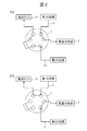
- FIG. 2 is a schematic view showing an example of connection of flow paths by the selector valve 5, (a) showing a state where the first flow path 11 is connected to the mass spectrometric section 2, and (b) showing a second flow path. 12 shows a state in which 12 is connected to the mass spectrometric section 2.
- the control unit 100 drives the selector valve 5 to switch the flow path connected to the mass analysis unit 2. As a result, either the first flow channel 11 or the second flow channel 12 is introduced into the mass spectrometric section 2. As shown in FIG. 2, the flow path that is not connected to the mass spectrometric section 2 is connected to the waste liquid tank 15, which prevents the solution from flowing out.
- FIG. 3 is a flowchart showing the operation of the liquid chromatograph mass spectrometer according to the first embodiment. The operation when an autosampler is used as the sampler 14 will be described below.
- the user prepares a sample in advance and introduces it into the sampler 14.
- an internal standard substance of known concentration By adding an internal standard substance of known concentration to the sample, it is possible to eliminate the influence of instability of adsorption and ionization in the flow channel, so that the signal intensity of the sample can be precisely quantified.
- the user After introducing the sample into the sampler 14, the user inputs an operation start instruction from the input unit of the mass spectrometer 2.
- the control unit 100 Upon receiving the operation start instruction, the control unit 100 operates the liquid chromatograph mass spectrometer in step S1 to start normal measurement. That is, the control unit 100 confirms that the first flow path 11 is connected to the mass spectrometric unit 2 by the selector valve 5, drives the liquid feed pumps 3a and 3b, and moves from the solution tanks 1a and 1b to the first position. The solution is introduced into the first channel 11.
- the pressure gauges 13a and 13b output the pressure values of the liquid feed pumps 3a and 3b to the control unit 100.
- the control unit 100 drives the sampler 14 to introduce the sample into the first flow path 11 and causes the mass spectrometric unit 2 to analyze the sample.
- the ion detector of the mass spectrometer 2 outputs the signal intensity of the sample and the signal intensity of the internal standard substance to the controller 100.
- the output signal of the ion detector may be ionic strength or ionic current.
- the data processing unit of the control unit 100 obtains a chromatogram based on the output signal of the ion detection unit.
- the display unit of the control unit 100 may receive the chromatogram from the data processing unit and display the chromatogram.
- step S2 the control unit 100 compares the signal intensity of the internal standard substance or the output value of the pressure gauges 13a and 13b with a predetermined threshold value stored in the storage unit. Thereby, the control unit 100 determines whether or not there is an abnormality in the measurement.
- the predetermined threshold is a value set based on, for example, a measured value obtained by past measurement or its variation, and the upper limit of the range of values obtained by normal measurement can be used as the threshold.
- No the control unit 100 returns to step S1 and continues normal measurement.
- step S3 the control unit 100 switches the selector valve 5, connects the second flow path 12 to the mass spectrometric unit 2, drives the liquid feed pump 3c, and supplies the solution from the solution tank 1c to the mass spectrometric unit 2. Liquid is delivered at a constant flow rate. Further, the control unit 100 receives the value of the pressure of the liquid feed pump 3c from the pressure gauge 13c.
- step S4 the control unit 100 compares the output value of the pressure gauge 13c with the predetermined threshold value stored in the storage unit.
- the predetermined threshold value to be compared with the output value of the pressure gauge 13c is set, for example, based on the pressure when no clogging has occurred. If there is a blockage between the selector valve 5 and the outlet of the capillary of the ion source, especially when the capillary of the ion source is clogged, the pressure measured by the pressure gauge 13c increases. Therefore, it is possible to determine whether or not there is a clogging between the selector valve 5 and the capillary outlet of the ion source depending on whether or not the pressure measured by the pressure gauge 13c is equal to or higher than the threshold value.
- the control unit 100 switches the selector valve 5 to connect the first flow path 11 to the mass spectrometric unit 2, and returns to step S1 to return to normal measurement.
- the control unit 100 displays, for example, a message requesting maintenance for eliminating the clogging of the ion source on the display unit, and stops the measurement operation.
- step S6 the process proceeds to step S6, and the user performs a recovery process to remove the clogging.
- the restoration process for example, the type and flow rate of the solution in the solution tank 1c are changed. Since the second flow passage 12 does not have a portion having a small conductance such as the separation column 4 on the flow passage, it is possible to directly apply the pressure to the clogged portion by increasing the flow rate, and efficiently push the clogging away. You can Further, as the solution introduced into the second flow path 12, a solvent that easily dissolves impurities (salt or polymer) that causes clogging can be used to efficiently remove clogging.
- the control unit 100 determines whether the output value of the pressure gauge 13c is less than a predetermined threshold value.
- the control unit 100 determines that the clogging has disappeared when the value of the pressure gauge 13c becomes less than the threshold value, switches the selector valve 5 to connect the first flow path 11 to the mass spectrometry unit 2, and returns to step S1. , Can return to normal measurement.
- an internal standard substance having a known concentration can be added to the solution flowing through the second flow path 12 in step S6. In this case, by monitoring the signal intensity of the internal standard substance in addition to the value of the pressure of the solution, it is possible to determine whether the state of the flow channel has returned to normal.
- the liquid chromatograph mass spectrometer switches from the first flow channel 11 to the second flow channel 12 that does not pass through the separation column 4 when the abnormality is detected, and The pressure of the second flow channel 12 is measured, and when the pressure of the second flow channel 12 is equal to or higher than a predetermined threshold value, it is possible to specify that the clogged portion is the ion source. .. Therefore, according to the present embodiment, it is possible to automatically identify the location where the clogging has occurred and to recover from the clogging in a short time.
- FIG. 4 is a schematic diagram showing the configuration of the liquid chromatograph mass spectrometer according to the second embodiment.
- the first flow channel 11 is branched into three, and three separation columns 4 passing through the branched first flow channels 11 are provided.
- the selector valves 6 and 7 (second valve) on the upstream side and the downstream side of the three separation columns 4, respectively, which is different from the first embodiment.
- the characteristics of the plurality of separation columns 4 may be the same or different.
- the control unit 100 controls driving of the selector valves 6 and 7 to select the separation column 4 to be used for measurement.
- the number of separation columns 4 is not limited to three, and other configurations and operations are the same as those in the first embodiment, and thus description thereof will be omitted.
- the liquid chromatograph mass spectrometer according to the present embodiment has the plurality of separation columns 4, the characteristics of the plurality of separation columns 4 can be different and the separation column 4 can be selected according to the characteristics of the sample to be measured.
- a plurality of separation columns 4 having similar characteristics can be used for parallel analysis, and the analysis can be introduced into the mass spectrometric section 2 for a time around the peak, which has the advantage of improving the throughput.
- the liquid chromatograph mass spectrometer of the present embodiment is provided with a plurality of separation columns 4, so that the number of selector valves increases and the flow path becomes complicated. Further, the selector valves 6 and 7 may be clogged, or carryover due to the sample remaining on the selector valves 6 and 7 may occur.
- the first flow path 11 is switched to the second flow path 12 that does not pass through the separation column 4, and the pressure in the second flow path 12 is measured. ..
- the pressure in the second flow path 12 is equal to or higher than a predetermined threshold value, it is possible to specify that the ion source is clogged, and when the pressure in the second flow path 12 is lower than the predetermined threshold value, separation is performed. It is possible to specify that the column 4 or the selector valve 6 or 7 is clogged. Therefore, according to the present embodiment, it is possible to automatically identify the location where the clogging has occurred and to recover from the clogging in a short time.
- FIG. 5 is a schematic diagram showing the configuration of the liquid chromatograph mass spectrometer according to the third embodiment.
- at least one of the plurality of separation columns 4 included in the liquid chromatograph mass spectrometer according to the second embodiment is a hollow dummy column 10, and the separation column 4
- the flow paths can be switched by the selector valves 6 and 7 (second valve) provided on the upstream side and the downstream side of the dummy column 10, respectively.
- the flow path that passes through the separation column 4 is the first flow path 11 and the flow path that passes through the dummy column 10 is the second flow path 12.
- the dummy column 10 is provided in parallel with the plurality of separation columns 4, and the second flow channel 12 is a flow channel that passes through the dummy column 10.
- the dummy column 10 is a hollow column with no packing material inside. Therefore, the dummy column 10 has a larger conductance than the separation column 4.
- the control unit 100 connects either one of the plurality of first flow paths 11 or the second flow path 12 to the mass analysis unit 2 by switching the selector valves 6 and 7.
- Other configurations of the device are the same as those in the first and second embodiments, and thus the description thereof will be omitted.
- step S1 the solution is sent from the solution tank 1a by the solution sending pump 3a (first solution sending pump).
- the control unit 100 switches the selector valves 6 and 7 (step S3), and the second flow through the dummy column 10 is performed.
- the path 12 is connected to the mass spectrometric section 2, the solution is sent from the solution tank 1b by the solution sending pump 3b (second solution sending pump), and the pressure in the second channel 12 is measured by the pressure gauge 13b (step S4).
- Other operations are the same as the operations in the first embodiment, and thus detailed description will be omitted.
- the second flow passage 12 is not a pipe as in the first embodiment, but a dummy column provided in parallel with the separation column 4 of the first flow passage 11.
- a configuration that passes through 10 it is possible to simplify the configuration of the device without providing a special flow path and reduce the manufacturing cost.
- the dummy column 10 can be removed similarly to the separation column 4, it can be easily replaced with another column.
- it is possible to determine whether there is a clogging between the liquid delivery pump 3b and the capillary outlet of the ion source it is possible to determine whether the clogging occurs on the separation column 4 side or the ion source side. It can be identified automatically and can recover from a clogging in a short time.
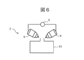
- FIG. 6 is a schematic diagram showing the configuration of the mass spectrometric unit according to the fourth embodiment.
- the mass spectrometer 2 has two or more ion source probes 9, and a selector valve 8 (the first valve for switching a plurality of ion source probes) is used. 3 valve) and is different from the first embodiment. Switching of the selector valve 8 is controlled by the control unit 100.
- the ion source probe 9 has a capillary, and the outlet of the capillary is arranged toward the vacuum chamber 16.
- the other device configuration is the same as that of the first embodiment, and thus the description thereof is omitted.
- the present embodiment similarly to the first embodiment, when an abnormality is detected, the first flow path 11 is switched to the second flow path 12 that does not pass through the separation column 4,
- the configuration is such that the pressure in the second flow path 12 is measured.
- the present embodiment it is possible to automatically identify the location where the clogging has occurred, and it is possible to recover from the clogging in a short time.
- the present embodiment has a configuration in which the flow path is switched to another ion source probe 9 when it is determined that there is a blockage between the selector valve 5 and the capillary outlet of the ion source. This makes it possible to recover from the clogging more reliably and in a short time.
- the present disclosure is not limited to the above-described embodiments and includes various modifications.
- the above-described embodiments have been described in detail in order to explain the present disclosure in an easy-to-understand manner, and it is not necessary to include all the configurations described.
- part of one embodiment can be replaced with the configuration of another embodiment.
- the configuration of another embodiment can be added to the configuration of one embodiment.
- a part of the configuration of each embodiment may be added, deleted, or replaced with a part of the configuration of another embodiment.
Landscapes
- Physics & Mathematics (AREA)
- Chemical & Material Sciences (AREA)
- Health & Medical Sciences (AREA)
- Life Sciences & Earth Sciences (AREA)
- Immunology (AREA)
- Analytical Chemistry (AREA)
- Biochemistry (AREA)
- General Health & Medical Sciences (AREA)
- General Physics & Mathematics (AREA)
- Pathology (AREA)
- Spectroscopy & Molecular Physics (AREA)
- Chemical Kinetics & Catalysis (AREA)
- Electrochemistry (AREA)
- Molecular Biology (AREA)
- Dispersion Chemistry (AREA)
- Other Investigation Or Analysis Of Materials By Electrical Means (AREA)
Priority Applications (3)
| Application Number | Priority Date | Filing Date | Title |
|---|---|---|---|
| US17/296,317 US11860142B2 (en) | 2018-12-10 | 2019-10-25 | Liquid chromatograph mass spectrometer |
| EP19897194.7A EP3896440B1 (en) | 2018-12-10 | 2019-10-25 | Liquid chromatograph mass spectrometer |
| CN201980077153.7A CN114127551B (zh) | 2018-12-10 | 2019-10-25 | 液相色谱质谱分析装置 |
Applications Claiming Priority (2)
| Application Number | Priority Date | Filing Date | Title |
|---|---|---|---|
| JP2018-230775 | 2018-12-10 | ||
| JP2018230775A JP6964065B2 (ja) | 2018-12-10 | 2018-12-10 | 液体クロマトグラフ質量分析装置 |
Publications (1)
| Publication Number | Publication Date |
|---|---|
| WO2020121660A1 true WO2020121660A1 (ja) | 2020-06-18 |
Family
ID=71077244
Family Applications (1)
| Application Number | Title | Priority Date | Filing Date |
|---|---|---|---|
| PCT/JP2019/042053 Ceased WO2020121660A1 (ja) | 2018-12-10 | 2019-10-25 | 液体クロマトグラフ質量分析装置 |
Country Status (5)
| Country | Link |
|---|---|
| US (1) | US11860142B2 (https=) |
| EP (1) | EP3896440B1 (https=) |
| JP (1) | JP6964065B2 (https=) |
| CN (1) | CN114127551B (https=) |
| WO (1) | WO2020121660A1 (https=) |
Cited By (3)
| Publication number | Priority date | Publication date | Assignee | Title |
|---|---|---|---|---|
| WO2022124187A1 (ja) * | 2020-12-11 | 2022-06-16 | 株式会社日立ハイテク | 自動分析装置の制御方法 |
| WO2023286612A1 (ja) * | 2021-07-12 | 2023-01-19 | 株式会社日立ハイテク | 質量分析システム、処理装置及び異常検出方法 |
| US11940427B2 (en) | 2020-10-28 | 2024-03-26 | Roche Diagnostics Operations, Inc. | Liquid chromatography—stream equivalence by single stream calibration |
Families Citing this family (10)
| Publication number | Priority date | Publication date | Assignee | Title |
|---|---|---|---|---|
| US12078620B2 (en) * | 2019-02-22 | 2024-09-03 | Hitachi High-Tech Corporation | Analysis apparatus |
| EP3786634B1 (en) * | 2019-08-27 | 2025-08-06 | Roche Diagnostics GmbH | Techniques for checking state of analyzers |
| US20210382021A1 (en) * | 2020-06-09 | 2021-12-09 | Waters Technologies Corporation | Systems and methods for two-dimensional liquid chromatography using size exclusion chromatography as a first dimension |
| US12163934B2 (en) * | 2020-06-22 | 2024-12-10 | Waters Technologies Corporation | Parallel insulated chromatography columns |
| JP7569389B2 (ja) * | 2020-12-24 | 2024-10-17 | 株式会社日立ハイテク | 液体クロマトグラフの制御方法および液体クロマトグラフ |
| EP4291888A1 (en) * | 2021-02-12 | 2023-12-20 | Roche Diagnostics GmbH | Column device |
| US12546757B2 (en) | 2021-05-13 | 2026-02-10 | Hitachi High-Tech Corporation | Method for adjusting pressure sensor and liquid chromatography analyzer |
| WO2024218866A1 (ja) * | 2023-04-18 | 2024-10-24 | 株式会社島津製作所 | 分析装置 |
| CN117571897B (zh) * | 2023-11-15 | 2024-04-30 | 青岛惠安康生物工程有限公司 | 一种液相色谱-质谱联用仪及切换装置 |
| CN120319652B (zh) * | 2025-06-12 | 2026-04-10 | 杭州谱育科技发展有限公司 | 一种用于质谱仪的电喷雾离子源控制方法及装置 |
Citations (8)
| Publication number | Priority date | Publication date | Assignee | Title |
|---|---|---|---|---|
| JP2000249694A (ja) | 1999-02-26 | 2000-09-14 | Shimadzu Corp | 液体クロマトグラフ分取装置 |
| JP2006215033A (ja) * | 2005-02-03 | 2006-08-17 | Agilent Technol Inc | 多次元的な分離のためのデバイス、システム及び分離方法 |
| JP2007213934A (ja) * | 2006-02-08 | 2007-08-23 | Hitachi Ltd | 質量分析装置及び質量分析方法 |
| JP2008209334A (ja) * | 2007-02-28 | 2008-09-11 | Hitachi High-Technologies Corp | 液体クロマトグラフィ装置 |
| JP2012145513A (ja) * | 2011-01-14 | 2012-08-02 | Hitachi High-Technologies Corp | 分析装置 |
| JP2012220245A (ja) * | 2011-04-05 | 2012-11-12 | Yokogawa Electric Corp | クロマトグラフ |
| WO2017103180A1 (en) * | 2015-12-18 | 2017-06-22 | F. Hoffmann-La Roche Ag | Automated clinical diagnostic system and method |
| WO2017164417A1 (ja) * | 2016-03-25 | 2017-09-28 | 科健化学株式会社 | 中空カラム液体クロマトグラフィーシステム及び該システムを用いた物質の分離 |
Family Cites Families (18)
| Publication number | Priority date | Publication date | Assignee | Title |
|---|---|---|---|---|
| US4391778A (en) * | 1981-09-30 | 1983-07-05 | The Ohio State University | Method and apparatus for the analysis of materials by chromatography and mass spectrometry |
| JPH0545350A (ja) * | 1991-08-13 | 1993-02-23 | Yamatake Honeywell Co Ltd | ガスクロマトグラフの減圧弁調整方法 |
| JPH11326302A (ja) * | 1998-05-13 | 1999-11-26 | Shimadzu Corp | 液体クロマトグラフ質量分析装置 |
| JP2001153875A (ja) | 1999-11-29 | 2001-06-08 | Olympus Optical Co Ltd | 自動分析装置 |
| JP3908142B2 (ja) * | 2002-10-02 | 2007-04-25 | 株式会社日立ハイテクノロジーズ | プラズマイオン源質量分析装置 |
| JP3996550B2 (ja) * | 2003-05-28 | 2007-10-24 | 株式会社日立ハイテクノロジーズ | アミノ酸分析装置 |
| JP2005257609A (ja) * | 2004-03-15 | 2005-09-22 | Shimadzu Corp | 液体クロマトグラフ装置 |
| JP4946647B2 (ja) * | 2007-06-14 | 2012-06-06 | 株式会社島津製作所 | 試料前処理装置及び液体クロマトグラフ装置 |
| JP5286134B2 (ja) | 2009-03-31 | 2013-09-11 | 株式会社日立ハイテクノロジーズ | 検体検査システムとその装置管理サーバの運用方法 |
| WO2013062624A1 (en) * | 2011-10-28 | 2013-05-02 | Thermo Finnigan Llc | Method and system for liquid chromatography fluidic monitoring |
| JP2014145675A (ja) * | 2013-01-29 | 2014-08-14 | Hitachi High-Technologies Corp | 分析装置、及びそれを用いて液体試料のクロマトグラムを取得する方法 |
| JP2015052533A (ja) | 2013-09-06 | 2015-03-19 | 株式会社日立製作所 | クロマトグラフィー装置およびクロマトグラフィー方法 |
| CN106662554B (zh) * | 2014-08-28 | 2019-04-02 | 株式会社岛津制作所 | 分析装置及分析方法 |
| CN105223264B (zh) * | 2015-09-21 | 2017-12-29 | 广东联捷生物科技有限公司 | 一种质谱定量分析的模拟内标方法、装置及应用 |
| CN105259273B (zh) * | 2015-11-01 | 2017-05-24 | 中国科学院成都生物研究所 | 耐盐液相色谱电喷雾质谱联用接口装置及其使用方法 |
| GB2564988B (en) | 2016-06-16 | 2021-12-08 | Hitachi High Tech Corp | Chromatographic mass analysis device and control method |
| JP6988158B2 (ja) * | 2017-05-11 | 2022-01-05 | 株式会社島津製作所 | 液体クロマトグラフ質量分析方法及び液体クロマトグラフ質量分析装置 |
| US11519886B2 (en) * | 2018-05-01 | 2022-12-06 | Shimadzu Corporation | Autosampler and liquid chromatograph |
-
2018
- 2018-12-10 JP JP2018230775A patent/JP6964065B2/ja active Active
-
2019
- 2019-10-25 WO PCT/JP2019/042053 patent/WO2020121660A1/ja not_active Ceased
- 2019-10-25 CN CN201980077153.7A patent/CN114127551B/zh active Active
- 2019-10-25 EP EP19897194.7A patent/EP3896440B1/en active Active
- 2019-10-25 US US17/296,317 patent/US11860142B2/en active Active
Patent Citations (8)
| Publication number | Priority date | Publication date | Assignee | Title |
|---|---|---|---|---|
| JP2000249694A (ja) | 1999-02-26 | 2000-09-14 | Shimadzu Corp | 液体クロマトグラフ分取装置 |
| JP2006215033A (ja) * | 2005-02-03 | 2006-08-17 | Agilent Technol Inc | 多次元的な分離のためのデバイス、システム及び分離方法 |
| JP2007213934A (ja) * | 2006-02-08 | 2007-08-23 | Hitachi Ltd | 質量分析装置及び質量分析方法 |
| JP2008209334A (ja) * | 2007-02-28 | 2008-09-11 | Hitachi High-Technologies Corp | 液体クロマトグラフィ装置 |
| JP2012145513A (ja) * | 2011-01-14 | 2012-08-02 | Hitachi High-Technologies Corp | 分析装置 |
| JP2012220245A (ja) * | 2011-04-05 | 2012-11-12 | Yokogawa Electric Corp | クロマトグラフ |
| WO2017103180A1 (en) * | 2015-12-18 | 2017-06-22 | F. Hoffmann-La Roche Ag | Automated clinical diagnostic system and method |
| WO2017164417A1 (ja) * | 2016-03-25 | 2017-09-28 | 科健化学株式会社 | 中空カラム液体クロマトグラフィーシステム及び該システムを用いた物質の分離 |
Non-Patent Citations (1)
| Title |
|---|
| See also references of EP3896440A4 |
Cited By (10)
| Publication number | Priority date | Publication date | Assignee | Title |
|---|---|---|---|---|
| US11940427B2 (en) | 2020-10-28 | 2024-03-26 | Roche Diagnostics Operations, Inc. | Liquid chromatography—stream equivalence by single stream calibration |
| WO2022124187A1 (ja) * | 2020-12-11 | 2022-06-16 | 株式会社日立ハイテク | 自動分析装置の制御方法 |
| JPWO2022124187A1 (https=) * | 2020-12-11 | 2022-06-16 | ||
| JP7574321B2 (ja) | 2020-12-11 | 2024-10-28 | 株式会社日立ハイテク | 自動分析装置の制御方法 |
| WO2023286612A1 (ja) * | 2021-07-12 | 2023-01-19 | 株式会社日立ハイテク | 質量分析システム、処理装置及び異常検出方法 |
| JP2023011436A (ja) * | 2021-07-12 | 2023-01-24 | 株式会社日立ハイテク | 質量分析システム、処理装置及び異常検出方法 |
| CN117597582A (zh) * | 2021-07-12 | 2024-02-23 | 株式会社日立高新技术 | 质量分析系统、处理装置以及异常检测方法 |
| US20240310338A1 (en) * | 2021-07-12 | 2024-09-19 | Hitachi High-Tech Corporation | Mass spectrometry system, processing device, and anomaly detection method |
| JP7695130B2 (ja) | 2021-07-12 | 2025-06-18 | 株式会社日立ハイテク | 質量分析システム、処理装置及び異常検出方法 |
| EP4372374A4 (en) * | 2021-07-12 | 2025-07-02 | Hitachi High Tech Corp | MASS SPECTROMETRY SYSTEM, PROCESSING DEVICE AND ANOMALY DETECTION METHOD |
Also Published As
| Publication number | Publication date |
|---|---|
| CN114127551A (zh) | 2022-03-01 |
| US20220050091A1 (en) | 2022-02-17 |
| CN114127551B (zh) | 2024-12-31 |
| EP3896440A4 (en) | 2022-08-17 |
| EP3896440B1 (en) | 2024-12-11 |
| US11860142B2 (en) | 2024-01-02 |
| JP2020094817A (ja) | 2020-06-18 |
| JP6964065B2 (ja) | 2021-11-10 |
| EP3896440A1 (en) | 2021-10-20 |
Similar Documents
| Publication | Publication Date | Title |
|---|---|---|
| JP6964065B2 (ja) | 液体クロマトグラフ質量分析装置 | |
| US10794874B2 (en) | Sample injection device | |
| JP2023523548A (ja) | 液体クロマトグラフィー流体流間の切り替えを含む分析システム及び方法 | |
| JP4457135B2 (ja) | 液体クロマトグラフ分析装置及び試料導入装置 | |
| WO2013008502A1 (ja) | 固相抽出装置および粘度測定装置 | |
| EP2703809B1 (en) | Mobile phase preparation device for liquid chromatography | |
| US8156788B2 (en) | Supercritical-phase mixed chromatography method and installation for implementing same | |
| JP7161595B2 (ja) | 液体クロマトグラフィー単流の較正による流れの等価性 | |
| WO2012095923A1 (ja) | 分析装置 | |
| US10753916B2 (en) | Systems, methods, and devices for detecting leaks in a chromatography system | |
| JP2000249694A (ja) | 液体クロマトグラフ分取装置 | |
| CN117980739A (zh) | 液相色谱质量分析装置的控制方法 | |
| CN114544795B (zh) | 质谱中气体流参数的异常检测 | |
| CN116569035A (zh) | 液相色谱仪的控制方法及液相色谱仪 | |
| US12607609B2 (en) | Systems and methods for a ventless gas chromatography mass spectrometry interface | |
| JP2006329656A (ja) | 流路切替バルブの内部液漏れ検出装置。 | |
| CN117981050A (zh) | 分析系统和方法 | |
| JP2025179823A (ja) | 純水の水質分析方法及び純水製造システムの運転方法 |
Legal Events
| Date | Code | Title | Description |
|---|---|---|---|
| 121 | Ep: the epo has been informed by wipo that ep was designated in this application |
Ref document number: 19897194 Country of ref document: EP Kind code of ref document: A1 |
|
| DPE2 | Request for preliminary examination filed before expiration of 19th month from priority date (pct application filed from 20040101) | ||
| NENP | Non-entry into the national phase |
Ref country code: DE |
|
| ENP | Entry into the national phase |
Ref document number: 2019897194 Country of ref document: EP Effective date: 20210712 |
|
| WWG | Wipo information: grant in national office |
Ref document number: 201980077153.7 Country of ref document: CN |