EP3896440B1 - Liquid chromatograph mass spectrometer - Google Patents
Liquid chromatograph mass spectrometer Download PDFInfo
- Publication number
- EP3896440B1 EP3896440B1 EP19897194.7A EP19897194A EP3896440B1 EP 3896440 B1 EP3896440 B1 EP 3896440B1 EP 19897194 A EP19897194 A EP 19897194A EP 3896440 B1 EP3896440 B1 EP 3896440B1
- Authority
- EP
- European Patent Office
- Prior art keywords
- flow path
- liquid
- mass spectrometry
- spectrometry unit
- feed pump
- Prior art date
- Legal status (The legal status is an assumption and is not a legal conclusion. Google has not performed a legal analysis and makes no representation as to the accuracy of the status listed.)
- Active
Links
Images


Classifications
-
- G—PHYSICS
- G01—MEASURING; TESTING
- G01N—INVESTIGATING OR ANALYSING MATERIALS BY DETERMINING THEIR CHEMICAL OR PHYSICAL PROPERTIES
- G01N30/00—Investigating or analysing materials by separation into components using adsorption, absorption or similar phenomena or using ion-exchange, e.g. chromatography or field flow fractionation
- G01N30/02—Column chromatography
- G01N30/26—Conditioning of the fluid carrier; Flow patterns
- G01N30/38—Flow patterns
- G01N30/46—Flow patterns using more than one column
- G01N30/466—Flow patterns using more than one column with separation columns in parallel
-
- G—PHYSICS
- G01—MEASURING; TESTING
- G01N—INVESTIGATING OR ANALYSING MATERIALS BY DETERMINING THEIR CHEMICAL OR PHYSICAL PROPERTIES
- G01N30/00—Investigating or analysing materials by separation into components using adsorption, absorption or similar phenomena or using ion-exchange, e.g. chromatography or field flow fractionation
- G01N30/02—Column chromatography
- G01N30/62—Detectors specially adapted therefor
- G01N30/72—Mass spectrometers
- G01N30/7233—Mass spectrometers interfaced to liquid or supercritical fluid chromatograph
- G01N30/724—Nebulising, aerosol formation or ionisation
- G01N30/7266—Nebulising, aerosol formation or ionisation by electric field, e.g. electrospray
-
- G—PHYSICS
- G01—MEASURING; TESTING
- G01N—INVESTIGATING OR ANALYSING MATERIALS BY DETERMINING THEIR CHEMICAL OR PHYSICAL PROPERTIES
- G01N27/00—Investigating or analysing materials by the use of electric, electrochemical, or magnetic means
- G01N27/62—Investigating or analysing materials by the use of electric, electrochemical, or magnetic means by investigating the ionisation of gases, e.g. aerosols; by investigating electric discharges, e.g. emission of cathode
- G01N27/622—Ion mobility spectrometry
- G01N27/623—Ion mobility spectrometry combined with mass spectrometry
-
- G—PHYSICS
- G01—MEASURING; TESTING
- G01N—INVESTIGATING OR ANALYSING MATERIALS BY DETERMINING THEIR CHEMICAL OR PHYSICAL PROPERTIES
- G01N30/00—Investigating or analysing materials by separation into components using adsorption, absorption or similar phenomena or using ion-exchange, e.g. chromatography or field flow fractionation
- G01N30/02—Column chromatography
- G01N30/26—Conditioning of the fluid carrier; Flow patterns
- G01N30/28—Control of physical parameters of the fluid carrier
- G01N30/32—Control of physical parameters of the fluid carrier of pressure or speed
-
- G—PHYSICS
- G01—MEASURING; TESTING
- G01N—INVESTIGATING OR ANALYSING MATERIALS BY DETERMINING THEIR CHEMICAL OR PHYSICAL PROPERTIES
- G01N30/00—Investigating or analysing materials by separation into components using adsorption, absorption or similar phenomena or using ion-exchange, e.g. chromatography or field flow fractionation
- G01N30/02—Column chromatography
- G01N30/26—Conditioning of the fluid carrier; Flow patterns
- G01N30/38—Flow patterns
- G01N30/46—Flow patterns using more than one column
-
- G—PHYSICS
- G01—MEASURING; TESTING
- G01N—INVESTIGATING OR ANALYSING MATERIALS BY DETERMINING THEIR CHEMICAL OR PHYSICAL PROPERTIES
- G01N30/00—Investigating or analysing materials by separation into components using adsorption, absorption or similar phenomena or using ion-exchange, e.g. chromatography or field flow fractionation
- G01N30/02—Column chromatography
- G01N30/62—Detectors specially adapted therefor
- G01N30/72—Mass spectrometers
- G01N30/7233—Mass spectrometers interfaced to liquid or supercritical fluid chromatograph
-
- G—PHYSICS
- G01—MEASURING; TESTING
- G01N—INVESTIGATING OR ANALYSING MATERIALS BY DETERMINING THEIR CHEMICAL OR PHYSICAL PROPERTIES
- G01N30/00—Investigating or analysing materials by separation into components using adsorption, absorption or similar phenomena or using ion-exchange, e.g. chromatography or field flow fractionation
- G01N30/02—Column chromatography
- G01N30/86—Signal analysis
- G01N30/8658—Optimising operation parameters
-
- G—PHYSICS
- G01—MEASURING; TESTING
- G01N—INVESTIGATING OR ANALYSING MATERIALS BY DETERMINING THEIR CHEMICAL OR PHYSICAL PROPERTIES
- G01N30/00—Investigating or analysing materials by separation into components using adsorption, absorption or similar phenomena or using ion-exchange, e.g. chromatography or field flow fractionation
- G01N30/02—Column chromatography
- G01N2030/022—Column chromatography characterised by the kind of separation mechanism
- G01N2030/027—Liquid chromatography
-
- G—PHYSICS
- G01—MEASURING; TESTING
- G01N—INVESTIGATING OR ANALYSING MATERIALS BY DETERMINING THEIR CHEMICAL OR PHYSICAL PROPERTIES
- G01N30/00—Investigating or analysing materials by separation into components using adsorption, absorption or similar phenomena or using ion-exchange, e.g. chromatography or field flow fractionation
- G01N30/02—Column chromatography
- G01N30/26—Conditioning of the fluid carrier; Flow patterns
- G01N30/28—Control of physical parameters of the fluid carrier
- G01N30/32—Control of physical parameters of the fluid carrier of pressure or speed
- G01N2030/324—Control of physical parameters of the fluid carrier of pressure or speed speed, flow rate
-
- G—PHYSICS
- G01—MEASURING; TESTING
- G01N—INVESTIGATING OR ANALYSING MATERIALS BY DETERMINING THEIR CHEMICAL OR PHYSICAL PROPERTIES
- G01N30/00—Investigating or analysing materials by separation into components using adsorption, absorption or similar phenomena or using ion-exchange, e.g. chromatography or field flow fractionation
- G01N30/02—Column chromatography
- G01N30/26—Conditioning of the fluid carrier; Flow patterns
- G01N30/38—Flow patterns
- G01N30/46—Flow patterns using more than one column
- G01N30/468—Flow patterns using more than one column involving switching between different column configurations
Definitions
- the present disclosure relates to a liquid chromatograph mass spectrometer.
- a mass spectrometer is an apparatus that ionizes a sample solution, introduces the ions into a vacuum device, separates and detects ions according to the mass-to-charge ratio (m/z), and can detect ions with high sensitivity and high accuracy.
- the mass spectrometer is generally used as a detector for, for example, a liquid chromatograph (LC), and a sample is analyzed by an analytical method called liquid chromatography-mass spectrometry (LC-MS).
- the liquid chromatography is a method in which a mobile phase containing a sample is pressurized with a liquid feed pump to pass through a separation column, and the sample is separated according to the difference in interaction (adsorption, partitioning, etc.) with the stationary phase of the separation column.
- the separation column is densely packed with fine porous particles as a stationary phase so that interaction with the sample is likely to occur. Therefore, if foreign matter such as dust is mixed in or impurities such as salt are accumulated, the separation column may be clogged and the sensitivity may be lowered. When the separation column is clogged, the conductance decreases and the pressure of the solution increases.
- a general LC liquid feed pump is equipped with a pressure gauge, it is possible to detect whether the separation column is clogged by a change in pressure when a constant flow rate of liquid is fed.
- JP 2008 209334 A discloses a liquid chromatography device which includes a separation column; a pump capable of sending liquid to the separation column; a sensor capable of detecting a pressure of the liquid sent by the pump; an upstream selector valve provided on the upstream the separation column, communicable with a waste liquid container; and a downstream selector valve provided on the downstream the separation column, communicable with the waste liquid container.
- the present disclosure provides a liquid chromatograph mass spectrometer capable of automatically specifying a location where a flow path is clogged and recovering in a short time.
- a liquid chromatograph mass spectrometer of the present disclosure includes a first flow path that passes through a separation column, a second flow path that does not pass through the separation column, a mass spectrometry unit that analyzes a sample that has passed through the first flow path, a first valve that connects any one of the first flow path and the second flow path to the mass spectrometry unit, a controller that controls driving of the first valve, and a pressure gauge that measures a pressure of the second flow path and outputs the pressure to the controller.
- the controller connects the first flow path to the mass spectrometry unit when the sample is analyzed in the mass spectrometry unit, and drives the first valve to connect the second flow path to the mass spectrometry unit in a case where it is determined to be abnormal when the measured value of the mass spectrometry unit and a predetermined threshold value are compared.
- FIG. 1 is a schematic diagram illustrating a configuration of a liquid chromatograph mass spectrometer according to a first embodiment.
- the liquid chromatograph mass spectrometer includes solution tanks 1a to 1c, a mass spectrometry unit 2, liquid feed pumps 3a to 3c, a separation column 4, a selector valve 5 (first valve), a first flow path 11, and a second flow path 12, pressure gauges 13a to 13c, a sampler 14, and a controller 100.
- the solution tanks 1a and 1b contain a solution to be a mobile phase.
- a solution generally used in liquid chromatography can be used depending on a sample.
- water, an aqueous solution of salts, an organic solvent such as methanol, acetonitrile or hexane may be used alone, or can be mixed and used.
- the solution tanks 1a and 1b are connected to the first flow path 11 via the liquid feed pumps 3a and 3b (first liquid feed pump), respectively.
- the solution tank 1c contains a solution to be fed to the second flow path 12, and is connected to the second flow path 12 via the liquid feed pump 3c (second liquid feed pump).
- the solution contained in the solution tank 1c may be the same as or different from the solution contained in the solution tanks 1a and 1b.
- the liquid feed pumps 3a to 3c pressurize and feed the solutions in the solution tanks 1a to 1c, respectively.
- the pressure gauges 13a and 13b are connected to the liquid feed pumps 3a and 3b that feed the solutions to the first flow path 11, respectively, and the pressure gauge 13c is connected to the liquid feed pumps 3c that feed the solution to the second flow path 12.
- the pressure gauges 13a to 13c measure the pressure of the solution flowing through the flow path, respectively. It is preferable to use the pressure gauges 13a to 13c capable of measuring a pressure in a range that can be pressurized by the liquid feed pumps 3a to 3c, typically a pressure of about 0 to 200 MPa. If the dead volume of the pressure gauges 13a to 13c is large, the time required for the pressure of the solution to stabilize is long. Therefore, it is preferable to reduce the dead volume of the pressure gauges 13a to 13c, typically 10 ⁇ L or less.
- the first flow path 11 and the second flow path 12 are composed of, for example, pipes.
- the sampler 14 is connected to the first flow path 11, and the separation column 4 is connected to the downstream side of the sampler 14.
- the sampler 14 for example, an autosampler, a manual injector, or the like can be used.
- the sample is introduced into the first flow path 11 by the sampler 14.
- the second flow path 12 is a flow path that does not pass through the separation column 4, and no sample is introduced into the second flow path 12.
- the liquid feed pumps 3a and 3b capable of feeding the liquid, typically, at a pressure of 0.1 to 100 MPa in order to obtain a sufficient flow rate for analysis.
- the second flow path 12 since the second flow path 12 has a higher conductance than the first flow path 11, a liquid feed pump having a lower pressure upper limit than the liquid feed pumps 3a and 3b feeding the liquid to the first flow path 11 as the liquid feed pump 3c feeding the liquid to the second flow path 12.
- the first flow path 11 and the second flow path 12 are connected to the selector valve 5, and by switching the selector valve 5, one of the first flow path 11 and the second flow path 12 is connected to the mass spectrometry unit 2. Details of the selector valve 5 will be described later.
- the selector valve 5 will be described later.
- the area from the solution tanks 1a and 1b to immediately before the mass spectrometry unit 2 may be referred to as a "liquid chromatograph (LC)".
- the mass spectrometry unit 2 has components such as an ion source, a vacuum chamber, and an ion detector, which are provided by a general mass spectrometer (MS).
- the mass spectrometry unit 2 ionizes the sample introduced from the first flow path 11 with the ion source, introduces ions into the vacuum chamber, separates ions for each mass-to-charge ratio (m/z), and detects the ionic strength by the ion detector.
- the ion detector outputs a detection signal of the ionic strength to the controller 100.
- the ion detector may output the ion current as a detection signal to the controller 100.
- the ion source examples include an electrospray ionization ion source, an atmospheric pressure chemical ionization ion source, and an atmospheric pressure photoionization ion source.
- the solution containing the sample is sprayed into the vacuum chamber through a capillary of an ion source probe.
- An inner diameter of an appropriate capillary depends on the flow rate of the liquid chromatograph (LC), and it is preferable to use a thinner capillary as the flow rate decreases.
- the inner diameter of a typical capillary is about 30 um to 150 um.
- the capillary with an inner diameter larger than 150 um is used, the ionization efficiency is lowered and the sample distribution is widened by diffusion while the solution flows through the capillary, so that the LC separability may be deteriorated. Since the capillary has a small inner diameter and may be heated depending on the ionization conditions, it is easily clogged due to the contamination of foreign substances and the accumulation of impurities.
- the controller 100 is a computer terminal such as a personal computer, and is configured to control the operation of the entire liquid chromatograph mass spectrometer.
- the controller 100 includes a data processor that processes the detection signal (measured value) of the ion detector of the mass spectrometry unit 2, a storage that stores various data, an input unit for a user to input an instruction to the liquid chromatograph mass spectrometer, and a display for displaying the results of mass spectrometry and various GUI screens, and the like.
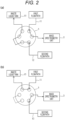
- FIG. 2 is a schematic diagram illustrating a connection example of the flow paths by the selector valve 5.
- FIG. 2(a) illustrates a state in which the first flow path 11 is connected to the mass spectrometry unit 2
- FIG. 2(b) illustrates a state that the second flow path 12 is connected to the mass spectrometry unit 2.
- the controller 100 drives the selector valve 5 to switch the flow path connected to the mass spectrometry unit 2. In this way, either one of the first flow path 11 and the second flow path 12 is introduced into the mass spectrometry unit 2. As illustrated in FIG. 2 , the flow path not connected to the mass spectrometry unit 2 is connected to a waste liquid tank 15, which prevents the solution from flowing out to the outside.
- FIG. 3 is a flowchart illustrating the operation of the liquid chromatograph mass spectrometer according to the first embodiment. The operation when an autosampler is used as the sampler 14 will be described below.
- the user prepares a sample in advance and introduces it into the sampler 14.
- an internal standard substance having a known concentration By adding an internal standard substance having a known concentration to the sample, the influence of adsorption on the flow path and instability of ionization can be eliminated, so that the signal strength of the sample can be accurately quantified.
- the user After introducing the sample into the sampler 14, the user inputs an operation start instruction from the input unit of the mass spectrometry unit 2.
- the controller 100 Upon receiving the operation start instruction, the controller 100 operates the liquid chromatograph mass spectrometer in Step S1 to start normal measurement. That is, the controller 100 confirms that the first flow path 11 is connected to the mass spectrometry unit 2 by the selector valve 5 and drives the liquid feed pumps 3a and 3b to introduce the solution from the solution tanks 1a and 1b into the first flow path 11.
- the pressure gauges 13a and 13b output the pressure values of the liquid feed pumps 3a and 3b to the controller 100.
- the controller 100 drives the sampler 14 to introduce the sample into the first flow path 11, and causes the mass spectrometry unit 2 to analyze the sample.
- the ion detector of the mass spectrometry unit 2 outputs the signal strength of the sample and the signal strength of the internal standard substance to the controller 100.
- the output signal of the ion detector may be an ionic strength or an ion current.
- the data processor of the controller 100 obtains a chromatogram based on the output signal of the ion detector.
- the display of the controller 100 may receive a chromatogram from the data processor and display the chromatogram.
- Step S2 the controller 100 compares the signal strength of the internal standard substance or the output values of the pressure gauges 13a and 13b with a predetermined threshold value stored in the storage. In this way, the controller 100 determines whether there is an abnormality in the measurement.
- the predetermined threshold value is, for example, a value set based on the measured value obtained by the past measurement or the variation thereof, and the upper limit of the range of the values obtained by the normal measurement can be set as the threshold value.
- the controller 100 determines that there is no abnormality (No)
- the controller 100 returns to Step S1 and continues the normal measurement.
- Step S3 the controller 100 switches the selector valve 5, connects the second flow path 12 to the mass spectrometry unit 2, and drives the liquid feed pump 3c to feed the solution from the solution tank 1c to the mass spectrometry unit 2 at a constant flow rate. Further, the controller 100 receives the pressure value of the liquid feed pump 3c from the pressure gauge 13c.
- Step S4 the controller 100 compares the output value of the pressure gauge 13c with a predetermined threshold value stored in the storage.
- the predetermined threshold value to be compared with the output value of the pressure gauge 13c is set based on, for example, the pressure in the absence of clogging. If the clogging occurs between the selector valve 5 and the outlet of the ion source capillary, especially in the ion source capillary, the pressure measured by the pressure gauge 13c rises. Therefore, it can be determined whether there is clogging between the selector valve 5 and the capillary outlet of the ion source depending on whether the pressure measured by the pressure gauge 13c is equal to or higher than the threshold value.
- Step S5 When the pressure measured by the pressure gauge 13c is less than the threshold value (No), it can be assumed that there is no clogging between the selector valve 5 and the capillary outlet of the ion source, and the clogging occurs on the LC side, that is, the separation column 4. After that, the process proceeds to Step S5, and the user replaces the separation column 4.
- the controller 100 detects that the separation column 4 has been replaced, the controller 100 switches the selector valve 5 to connect the first flow path 11 to the mass spectrometry unit 2, returns to Step S1, and returns to the normal measurement.
- the controller 100 displays, for example, a message requesting maintenance for clearing the clogging of the ion source on the display, and stops the measurement operation.
- Step S6 the process proceeds to Step S6, and the user performs a restoration process for clearing the clogging.
- the restoration process for example, the type or the flow rate of the solution in the solution tank 1c is changed. Since the second flow path 12 does not have a part having a small conductance such as the separation column 4 on the flow path, pressure can be directly applied to the clogged part by increasing the flow rate, and the clogging can be efficiently washed away. Further, by using a solvent that easily dissolves impurities (salts and polymers) that cause clogging as the solution to be introduced into the second flow path 12, the clogging can be efficiently removed.
- the controller 100 determines whether the output value of the pressure gauge 13c is less than a predetermined threshold value.
- the controller 100 determines that the clogging has disappeared when the value of the pressure gauge 13c is less than the threshold value, switches the selector valve 5, connects the first flow path 11 to the mass spectrometry unit 2, returns to Step S1, and can return to normal measurement. It is also possible to add an internal standard substance having a known concentration to the solution flowing through the second flow path 12 in Step S6. In this case, by monitoring the signal strength of the internal standard substance in addition to the pressure value of the solution, it is possible to determine whether the state of the flow path has returned to normal.
- the liquid chromatograph mass spectrometer when the liquid chromatograph mass spectrometer according to this embodiment detects an abnormality, the liquid chromatograph mass spectrometer switches from the first flow path 11 to the second flow path 12 that does not pass through the separation column 4, measures the pressure of the second flow path 12.
- the pressure of the second flow path 12 is equal to or higher than the predetermined threshold value, it is possible to specify the location where the clogging has occurred as an ion source. Therefore, according to this embodiment, the location where the clogging has occurred can be automatically identified, and the recovering from the clogging can be achieved in a short time.
- FIG. 4 is a schematic diagram illustrating a configuration of a liquid chromatograph mass spectrometer according to a second embodiment.
- the liquid chromatograph mass spectrometer according to this embodiment is different from the first embodiment in that the first flow path 11 is branched into three, and each of the three separation columns 4 passes through the branched first flow path 11, and there are included selector valves 6 and 7 (second valves) on the upstream side and the downstream side of the three separation columns 4, respectively.
- the characteristics of the plurality of separation columns 4 may be similar or different from each other.
- the controller 100 controls the drive of the selector valves 6 and 7 to select the separation column 4 to be used for measurement.
- the number of the separation columns 4 is not limited to three. Other configurations and operations are the same as those in the first embodiment, and thus the description thereof will be omitted.
- the liquid chromatograph mass spectrometer has the plurality of separation columns 4, the characteristics of the plurality of separation columns 4 can be made different, and the separation column 4 can be selected according to the characteristics of the sample to be measured.
- analysis can be performed in parallel using a plurality of separation columns 4 having similar characteristics, and the sample can be introduced into the mass spectrometry unit 2 only for a time near the peak, which has an advantage that the throughput can be improved.
- the liquid chromatograph mass spectrometer of this embodiment includes the plurality of separation columns 4, which increases the number of selector valves and complicates the flow path.
- the selector valves 6 and 7 may be clogged, or carryover may occur due to the sample remaining in the selector valves 6 and 7.
- the first flow path 11 is switched to the second flow path 12 that does not pass through the separation column 4, and the pressure of the second flow path 12 is measured.
- the pressure of the second flow path 12 is equal to or higher than the predetermined threshold value, it can be specified that the ion source is clogged, and when the pressure of the second flow path 12 is lower than the predetermined threshold value, it can be specified that any of the separation column 4 and the selector valves 6 and 7 is clogged. Therefore, according to this embodiment, the location where the clogging has occurred can be automatically identified, and the recovering from the clogging can be achieved in a short time.
- FIG. 5 is a schematic diagram illustrating a configuration of a liquid chromatograph mass spectrometer according to a third embodiment.
- at least one of the plurality of separation columns 4 provided in the liquid chromatograph mass spectrometer according to the second embodiment is a hollow dummy column 10, and the flow path can be switched by the selector valves 6 and 7 (second valves) provided in the upstream side and the downstream side of the separation column 4 and the dummy column 10 respectively.
- the selector valves 6 and 7 second valves
- the flow path that passes through the separation column 4 is referred to as the first flow path 11
- the flow path that passes through the dummy column 10 is referred to as the second flow path 12.
- the dummy column 10 is provided in parallel with the plurality of separation columns 4, and the second flow path 12 is a flow path passing through the dummy column 10.
- the dummy column 10 is a hollow column without a filler inside. Therefore, the dummy column 10 has a larger conductance than the separation column 4.
- the controller 100 connects any of the plurality of first flow paths 11 and the second flow path 12 to the mass spectrometry unit 2 by switching the selector valves 6 and 7. Since other apparatus configurations are the same as those of the first embodiment and the second embodiment, the description thereof will be omitted.
- Step S1 illustrated in FIG. 3 liquid is fed from the solution tank 1a by the liquid feed pump 3a (first liquid feed pump). If it is determined to be abnormal during the normal measurement (Yes in Step S2 illustrated in FIG. 3 ), the controller 100 switches the selector valves 6 and 7 (Step S3) to connect the second flow path 12 passing through the dummy column 10 to the mass spectrometry unit 2. Then, the controller 100 feeds the solution from the solution tank 1b by the liquid feed pump 3b (second liquid feed pump), and measures the pressure of the second flow path 12 by the pressure gauge 13b (Step S4). Since other operations are the same as the operations in the first embodiment, detailed description thereof will be omitted.
- the second flow path 12 is configured to pass through the dummy column 10 provided in parallel with the separation column 4 of the first flow path 11 instead of the piping as in the first embodiment. Therefore, it is possible to simplify the configuration of the apparatus without the need of any special flow path, and reduce the manufacturing cost. Further, since the dummy column 10 can be removed like the separation column 4, it can be easily replaced with another column. Furthermore, since it is possible to determine whether there is clogging between the liquid feed pump 3b and the capillary outlet of the ion source, it is possible to automatically specify whether the clogging occurs on the separation column 4 side or the ion source side, and it can be recovered from the clogging in a short time.
- FIG. 6 is a schematic diagram illustrating a configuration of a mass spectrometry unit according to the fourth embodiment.
- the liquid chromatograph mass spectrometer of this embodiment is different from the first embodiment in that the mass spectrometry unit 2 has two or more ion source probes 9, and a selector valve 8 (third valve) for switching between a plurality of ion source probes are included. Switching of the selector valve 8 is controlled by the controller 100.
- the ion source probe 9 has a capillary, and the outlet of the capillary is arranged toward a vacuum chamber 16. Since other apparatus configurations are the same as those in the first embodiment, description thereof will be omitted.
- Step S1 in the first embodiment the controller 100 switches the selector valve 8 in Step S5 to connect another ion source probe to the mass spectrometry unit 2. In this way, when it is determined that the ion source is clogged, it is possible to recover from the clogging more reliably and in a short time by switching the ion source probe 9.
- the liquid chromatograph mass spectrometer is configured to switch from the first flow path 11 to the second flow path 12 that does not pass through the separation column 4 when an abnormality is detected so as to measure the pressure of the second flow path 12.
- the location where the clogging has occurred can be automatically identified, and the recovering from the clogging can be achieved in a short time.
- this embodiment has a configuration in which the flow path is switched to another ion source probe 9 when it is determined that there is clogging between the selector valve 5 and the capillary outlet of the ion source. As a result, it is possible to recover from the clogging more reliably and in a short time.
Landscapes
- Physics & Mathematics (AREA)
- Chemical & Material Sciences (AREA)
- Health & Medical Sciences (AREA)
- Life Sciences & Earth Sciences (AREA)
- Immunology (AREA)
- Analytical Chemistry (AREA)
- Biochemistry (AREA)
- General Health & Medical Sciences (AREA)
- General Physics & Mathematics (AREA)
- Pathology (AREA)
- Spectroscopy & Molecular Physics (AREA)
- Chemical Kinetics & Catalysis (AREA)
- Electrochemistry (AREA)
- Molecular Biology (AREA)
- Dispersion Chemistry (AREA)
- Other Investigation Or Analysis Of Materials By Electrical Means (AREA)
Applications Claiming Priority (2)
| Application Number | Priority Date | Filing Date | Title |
|---|---|---|---|
| JP2018230775A JP6964065B2 (ja) | 2018-12-10 | 2018-12-10 | 液体クロマトグラフ質量分析装置 |
| PCT/JP2019/042053 WO2020121660A1 (ja) | 2018-12-10 | 2019-10-25 | 液体クロマトグラフ質量分析装置 |
Publications (3)
| Publication Number | Publication Date |
|---|---|
| EP3896440A1 EP3896440A1 (en) | 2021-10-20 |
| EP3896440A4 EP3896440A4 (en) | 2022-08-17 |
| EP3896440B1 true EP3896440B1 (en) | 2024-12-11 |
Family
ID=71077244
Family Applications (1)
| Application Number | Title | Priority Date | Filing Date |
|---|---|---|---|
| EP19897194.7A Active EP3896440B1 (en) | 2018-12-10 | 2019-10-25 | Liquid chromatograph mass spectrometer |
Country Status (5)
| Country | Link |
|---|---|
| US (1) | US11860142B2 (https=) |
| EP (1) | EP3896440B1 (https=) |
| JP (1) | JP6964065B2 (https=) |
| CN (1) | CN114127551B (https=) |
| WO (1) | WO2020121660A1 (https=) |
Families Citing this family (13)
| Publication number | Priority date | Publication date | Assignee | Title |
|---|---|---|---|---|
| US12078620B2 (en) * | 2019-02-22 | 2024-09-03 | Hitachi High-Tech Corporation | Analysis apparatus |
| EP3786634B1 (en) * | 2019-08-27 | 2025-08-06 | Roche Diagnostics GmbH | Techniques for checking state of analyzers |
| US20210382021A1 (en) * | 2020-06-09 | 2021-12-09 | Waters Technologies Corporation | Systems and methods for two-dimensional liquid chromatography using size exclusion chromatography as a first dimension |
| US12163934B2 (en) * | 2020-06-22 | 2024-12-10 | Waters Technologies Corporation | Parallel insulated chromatography columns |
| ES3015159T3 (en) * | 2020-10-28 | 2025-04-29 | Hoffmann La Roche | Liquid chromatography - stream equivalence by single stream calibration |
| US20230417781A1 (en) * | 2020-12-11 | 2023-12-28 | Hitachi High-Tech Corporation | Method of controlling automatic analyzer |
| JP7569389B2 (ja) * | 2020-12-24 | 2024-10-17 | 株式会社日立ハイテク | 液体クロマトグラフの制御方法および液体クロマトグラフ |
| EP4291888A1 (en) * | 2021-02-12 | 2023-12-20 | Roche Diagnostics GmbH | Column device |
| US12546757B2 (en) | 2021-05-13 | 2026-02-10 | Hitachi High-Tech Corporation | Method for adjusting pressure sensor and liquid chromatography analyzer |
| JP7695130B2 (ja) * | 2021-07-12 | 2025-06-18 | 株式会社日立ハイテク | 質量分析システム、処理装置及び異常検出方法 |
| WO2024218866A1 (ja) * | 2023-04-18 | 2024-10-24 | 株式会社島津製作所 | 分析装置 |
| CN117571897B (zh) * | 2023-11-15 | 2024-04-30 | 青岛惠安康生物工程有限公司 | 一种液相色谱-质谱联用仪及切换装置 |
| CN120319652B (zh) * | 2025-06-12 | 2026-04-10 | 杭州谱育科技发展有限公司 | 一种用于质谱仪的电喷雾离子源控制方法及装置 |
Family Cites Families (26)
| Publication number | Priority date | Publication date | Assignee | Title |
|---|---|---|---|---|
| US4391778A (en) * | 1981-09-30 | 1983-07-05 | The Ohio State University | Method and apparatus for the analysis of materials by chromatography and mass spectrometry |
| JPH0545350A (ja) * | 1991-08-13 | 1993-02-23 | Yamatake Honeywell Co Ltd | ガスクロマトグラフの減圧弁調整方法 |
| JPH11326302A (ja) * | 1998-05-13 | 1999-11-26 | Shimadzu Corp | 液体クロマトグラフ質量分析装置 |
| JP2000249694A (ja) | 1999-02-26 | 2000-09-14 | Shimadzu Corp | 液体クロマトグラフ分取装置 |
| JP2001153875A (ja) | 1999-11-29 | 2001-06-08 | Olympus Optical Co Ltd | 自動分析装置 |
| JP3908142B2 (ja) * | 2002-10-02 | 2007-04-25 | 株式会社日立ハイテクノロジーズ | プラズマイオン源質量分析装置 |
| JP3996550B2 (ja) * | 2003-05-28 | 2007-10-24 | 株式会社日立ハイテクノロジーズ | アミノ酸分析装置 |
| JP2005257609A (ja) * | 2004-03-15 | 2005-09-22 | Shimadzu Corp | 液体クロマトグラフ装置 |
| US20060171855A1 (en) * | 2005-02-03 | 2006-08-03 | Hongfeng Yin | Devices,systems and methods for multi-dimensional separation |
| JP4982087B2 (ja) | 2006-02-08 | 2012-07-25 | 株式会社日立製作所 | 質量分析装置及び質量分析方法 |
| JP5028109B2 (ja) * | 2007-02-28 | 2012-09-19 | 株式会社日立ハイテクノロジーズ | 液体クロマトグラフ装置 |
| JP4946647B2 (ja) * | 2007-06-14 | 2012-06-06 | 株式会社島津製作所 | 試料前処理装置及び液体クロマトグラフ装置 |
| JP5286134B2 (ja) | 2009-03-31 | 2013-09-11 | 株式会社日立ハイテクノロジーズ | 検体検査システムとその装置管理サーバの運用方法 |
| WO2013062624A1 (en) * | 2011-10-28 | 2013-05-02 | Thermo Finnigan Llc | Method and system for liquid chromatography fluidic monitoring |
| JP2012145513A (ja) * | 2011-01-14 | 2012-08-02 | Hitachi High-Technologies Corp | 分析装置 |
| JP5545494B2 (ja) | 2011-04-05 | 2014-07-09 | 横河電機株式会社 | クロマトグラフ |
| JP2014145675A (ja) * | 2013-01-29 | 2014-08-14 | Hitachi High-Technologies Corp | 分析装置、及びそれを用いて液体試料のクロマトグラムを取得する方法 |
| JP2015052533A (ja) | 2013-09-06 | 2015-03-19 | 株式会社日立製作所 | クロマトグラフィー装置およびクロマトグラフィー方法 |
| CN106662554B (zh) * | 2014-08-28 | 2019-04-02 | 株式会社岛津制作所 | 分析装置及分析方法 |
| CN105223264B (zh) * | 2015-09-21 | 2017-12-29 | 广东联捷生物科技有限公司 | 一种质谱定量分析的模拟内标方法、装置及应用 |
| CN105259273B (zh) * | 2015-11-01 | 2017-05-24 | 中国科学院成都生物研究所 | 耐盐液相色谱电喷雾质谱联用接口装置及其使用方法 |
| JP6694509B2 (ja) * | 2015-12-18 | 2020-05-13 | エフ ホフマン−ラ ロッシュ アクチェン ゲゼルシャフト | 自動化された臨床診断システムおよび方法 |
| WO2017163413A1 (ja) * | 2016-03-25 | 2017-09-28 | 科健化学株式会社 | 中空カラム液体クロマトグラフィーシステム及び該システムを用いた物質の分離 |
| GB2564988B (en) | 2016-06-16 | 2021-12-08 | Hitachi High Tech Corp | Chromatographic mass analysis device and control method |
| JP6988158B2 (ja) * | 2017-05-11 | 2022-01-05 | 株式会社島津製作所 | 液体クロマトグラフ質量分析方法及び液体クロマトグラフ質量分析装置 |
| US11519886B2 (en) * | 2018-05-01 | 2022-12-06 | Shimadzu Corporation | Autosampler and liquid chromatograph |
-
2018
- 2018-12-10 JP JP2018230775A patent/JP6964065B2/ja active Active
-
2019
- 2019-10-25 WO PCT/JP2019/042053 patent/WO2020121660A1/ja not_active Ceased
- 2019-10-25 CN CN201980077153.7A patent/CN114127551B/zh active Active
- 2019-10-25 EP EP19897194.7A patent/EP3896440B1/en active Active
- 2019-10-25 US US17/296,317 patent/US11860142B2/en active Active
Also Published As
| Publication number | Publication date |
|---|---|
| WO2020121660A1 (ja) | 2020-06-18 |
| CN114127551A (zh) | 2022-03-01 |
| US20220050091A1 (en) | 2022-02-17 |
| CN114127551B (zh) | 2024-12-31 |
| EP3896440A4 (en) | 2022-08-17 |
| US11860142B2 (en) | 2024-01-02 |
| JP2020094817A (ja) | 2020-06-18 |
| JP6964065B2 (ja) | 2021-11-10 |
| EP3896440A1 (en) | 2021-10-20 |
Similar Documents
| Publication | Publication Date | Title |
|---|---|---|
| EP3896440B1 (en) | Liquid chromatograph mass spectrometer | |
| US10794874B2 (en) | Sample injection device | |
| US8968560B2 (en) | Chromatography using multiple detectors | |
| KR102498445B1 (ko) | 이온의 농도를 검출하는 검출기 및 이를 구비하는 이온 크로마토그래피 장치 | |
| WO2013008502A1 (ja) | 固相抽出装置および粘度測定装置 | |
| EP3786635B1 (en) | Techniques for checking state of lc/ms analyzers | |
| EP3933399B1 (en) | Liquid chromatographic analyzer and control method thereof | |
| JPWO2017037829A1 (ja) | 高分子化合物の定量分析方法及び該定量分析のためのデータ処理装置 | |
| CN113237986B (zh) | 液相色谱仪及分析执行方法 | |
| US10753916B2 (en) | Systems, methods, and devices for detecting leaks in a chromatography system | |
| WO2012095923A1 (ja) | 分析装置 | |
| US20240310338A1 (en) | Mass spectrometry system, processing device, and anomaly detection method | |
| Kadmi et al. | A highly sensitive liquid chromatography-tandem mass spectrometry method for the analysis of a toxic water disinfection by-product, N-nitrosomethylethylamine | |
| JP2017187369A (ja) | 対象物質の分析方法及び分析装置 | |
| WO2024038777A1 (ja) | 不純物取得システム、品質検査システムおよび液体製造供給システム | |
| CN117980739A (zh) | 液相色谱质量分析装置的控制方法 | |
| JP2000249694A (ja) | 液体クロマトグラフ分取装置 | |
| CN114544795B (zh) | 质谱中气体流参数的异常检测 | |
| CN117136301A (zh) | 具有hplc的自动分析装置以及该自动分析装置的控制方法 | |
| JP2006329656A (ja) | 流路切替バルブの内部液漏れ検出装置。 | |
| EP4194849B1 (en) | Monitoring and preventing suppressor failures | |
| EP3840014A1 (en) | Automated method for maintaining a clinical diagnostics system | |
| CN121844206A (zh) | 用于无排气气相色谱质谱接口的系统和方法 | |
| Muller et al. | LC Coupled to MS–a User Report | |
| JP2025179823A (ja) | 純水の水質分析方法及び純水製造システムの運転方法 |
Legal Events
| Date | Code | Title | Description |
|---|---|---|---|
| STAA | Information on the status of an ep patent application or granted ep patent |
Free format text: STATUS: THE INTERNATIONAL PUBLICATION HAS BEEN MADE |
|
| PUAI | Public reference made under article 153(3) epc to a published international application that has entered the european phase |
Free format text: ORIGINAL CODE: 0009012 |
|
| STAA | Information on the status of an ep patent application or granted ep patent |
Free format text: STATUS: REQUEST FOR EXAMINATION WAS MADE |
|
| 17P | Request for examination filed |
Effective date: 20210712 |
|
| AK | Designated contracting states |
Kind code of ref document: A1 Designated state(s): AL AT BE BG CH CY CZ DE DK EE ES FI FR GB GR HR HU IE IS IT LI LT LU LV MC MK MT NL NO PL PT RO RS SE SI SK SM TR |
|
| DAV | Request for validation of the european patent (deleted) | ||
| DAX | Request for extension of the european patent (deleted) | ||
| REG | Reference to a national code |
Ref legal event code: R079 Ipc: G01N0030320000 Ref country code: DE Ref legal event code: R079 Ref document number: 602019063504 Country of ref document: DE Free format text: PREVIOUS MAIN CLASS: G01N0027620000 Ipc: G01N0030320000 |
|
| A4 | Supplementary search report drawn up and despatched |
Effective date: 20220715 |
|
| RIC1 | Information provided on ipc code assigned before grant |
Ipc: G01N 30/32 20060101AFI20220711BHEP |
|
| GRAP | Despatch of communication of intention to grant a patent |
Free format text: ORIGINAL CODE: EPIDOSNIGR1 |
|
| STAA | Information on the status of an ep patent application or granted ep patent |
Free format text: STATUS: GRANT OF PATENT IS INTENDED |
|
| INTG | Intention to grant announced |
Effective date: 20240726 |
|
| GRAS | Grant fee paid |
Free format text: ORIGINAL CODE: EPIDOSNIGR3 |
|
| GRAA | (expected) grant |
Free format text: ORIGINAL CODE: 0009210 |
|
| STAA | Information on the status of an ep patent application or granted ep patent |
Free format text: STATUS: THE PATENT HAS BEEN GRANTED |
|
| AK | Designated contracting states |
Kind code of ref document: B1 Designated state(s): AL AT BE BG CH CY CZ DE DK EE ES FI FR GB GR HR HU IE IS IT LI LT LU LV MC MK MT NL NO PL PT RO RS SE SI SK SM TR |
|
| REG | Reference to a national code |
Ref country code: GB Ref legal event code: FG4D |
|
| REG | Reference to a national code |
Ref country code: CH Ref legal event code: EP |
|
| REG | Reference to a national code |
Ref country code: DE Ref legal event code: R096 Ref document number: 602019063504 Country of ref document: DE |
|
| REG | Reference to a national code |
Ref country code: IE Ref legal event code: FG4D |
|
| REG | Reference to a national code |
Ref country code: LT Ref legal event code: MG9D |
|
| PG25 | Lapsed in a contracting state [announced via postgrant information from national office to epo] |
Ref country code: HR Free format text: LAPSE BECAUSE OF FAILURE TO SUBMIT A TRANSLATION OF THE DESCRIPTION OR TO PAY THE FEE WITHIN THE PRESCRIBED TIME-LIMIT Effective date: 20241211 |
|
| PG25 | Lapsed in a contracting state [announced via postgrant information from national office to epo] |
Ref country code: FI Free format text: LAPSE BECAUSE OF FAILURE TO SUBMIT A TRANSLATION OF THE DESCRIPTION OR TO PAY THE FEE WITHIN THE PRESCRIBED TIME-LIMIT Effective date: 20241211 |
|
| PG25 | Lapsed in a contracting state [announced via postgrant information from national office to epo] |
Ref country code: BG Free format text: LAPSE BECAUSE OF FAILURE TO SUBMIT A TRANSLATION OF THE DESCRIPTION OR TO PAY THE FEE WITHIN THE PRESCRIBED TIME-LIMIT Effective date: 20241211 |
|
| REG | Reference to a national code |
Ref country code: NL Ref legal event code: MP Effective date: 20241211 |
|
| PG25 | Lapsed in a contracting state [announced via postgrant information from national office to epo] |
Ref country code: ES Free format text: LAPSE BECAUSE OF FAILURE TO SUBMIT A TRANSLATION OF THE DESCRIPTION OR TO PAY THE FEE WITHIN THE PRESCRIBED TIME-LIMIT Effective date: 20241211 |
|
| PG25 | Lapsed in a contracting state [announced via postgrant information from national office to epo] |
Ref country code: NO Free format text: LAPSE BECAUSE OF FAILURE TO SUBMIT A TRANSLATION OF THE DESCRIPTION OR TO PAY THE FEE WITHIN THE PRESCRIBED TIME-LIMIT Effective date: 20250311 |
|
| PG25 | Lapsed in a contracting state [announced via postgrant information from national office to epo] |
Ref country code: GR Free format text: LAPSE BECAUSE OF FAILURE TO SUBMIT A TRANSLATION OF THE DESCRIPTION OR TO PAY THE FEE WITHIN THE PRESCRIBED TIME-LIMIT Effective date: 20250312 Ref country code: LV Free format text: LAPSE BECAUSE OF FAILURE TO SUBMIT A TRANSLATION OF THE DESCRIPTION OR TO PAY THE FEE WITHIN THE PRESCRIBED TIME-LIMIT Effective date: 20241211 |
|
| PG25 | Lapsed in a contracting state [announced via postgrant information from national office to epo] |
Ref country code: RS Free format text: LAPSE BECAUSE OF FAILURE TO SUBMIT A TRANSLATION OF THE DESCRIPTION OR TO PAY THE FEE WITHIN THE PRESCRIBED TIME-LIMIT Effective date: 20250311 |
|
| PG25 | Lapsed in a contracting state [announced via postgrant information from national office to epo] |
Ref country code: NL Free format text: LAPSE BECAUSE OF FAILURE TO SUBMIT A TRANSLATION OF THE DESCRIPTION OR TO PAY THE FEE WITHIN THE PRESCRIBED TIME-LIMIT Effective date: 20241211 |
|
| REG | Reference to a national code |
Ref country code: AT Ref legal event code: MK05 Ref document number: 1750762 Country of ref document: AT Kind code of ref document: T Effective date: 20241211 |
|
| PG25 | Lapsed in a contracting state [announced via postgrant information from national office to epo] |
Ref country code: SM Free format text: LAPSE BECAUSE OF FAILURE TO SUBMIT A TRANSLATION OF THE DESCRIPTION OR TO PAY THE FEE WITHIN THE PRESCRIBED TIME-LIMIT Effective date: 20241211 |
|
| PG25 | Lapsed in a contracting state [announced via postgrant information from national office to epo] |
Ref country code: PL Free format text: LAPSE BECAUSE OF FAILURE TO SUBMIT A TRANSLATION OF THE DESCRIPTION OR TO PAY THE FEE WITHIN THE PRESCRIBED TIME-LIMIT Effective date: 20241211 |
|
| PG25 | Lapsed in a contracting state [announced via postgrant information from national office to epo] |
Ref country code: IS Free format text: LAPSE BECAUSE OF FAILURE TO SUBMIT A TRANSLATION OF THE DESCRIPTION OR TO PAY THE FEE WITHIN THE PRESCRIBED TIME-LIMIT Effective date: 20250411 |
|
| PG25 | Lapsed in a contracting state [announced via postgrant information from national office to epo] |
Ref country code: PT Free format text: LAPSE BECAUSE OF FAILURE TO SUBMIT A TRANSLATION OF THE DESCRIPTION OR TO PAY THE FEE WITHIN THE PRESCRIBED TIME-LIMIT Effective date: 20250411 |
|
| PG25 | Lapsed in a contracting state [announced via postgrant information from national office to epo] |
Ref country code: EE Free format text: LAPSE BECAUSE OF FAILURE TO SUBMIT A TRANSLATION OF THE DESCRIPTION OR TO PAY THE FEE WITHIN THE PRESCRIBED TIME-LIMIT Effective date: 20241211 |
|
| PG25 | Lapsed in a contracting state [announced via postgrant information from national office to epo] |
Ref country code: RO Free format text: LAPSE BECAUSE OF FAILURE TO SUBMIT A TRANSLATION OF THE DESCRIPTION OR TO PAY THE FEE WITHIN THE PRESCRIBED TIME-LIMIT Effective date: 20241211 Ref country code: AT Free format text: LAPSE BECAUSE OF FAILURE TO SUBMIT A TRANSLATION OF THE DESCRIPTION OR TO PAY THE FEE WITHIN THE PRESCRIBED TIME-LIMIT Effective date: 20241211 |
|
| PG25 | Lapsed in a contracting state [announced via postgrant information from national office to epo] |
Ref country code: SK Free format text: LAPSE BECAUSE OF FAILURE TO SUBMIT A TRANSLATION OF THE DESCRIPTION OR TO PAY THE FEE WITHIN THE PRESCRIBED TIME-LIMIT Effective date: 20241211 |
|
| PG25 | Lapsed in a contracting state [announced via postgrant information from national office to epo] |
Ref country code: CZ Free format text: LAPSE BECAUSE OF FAILURE TO SUBMIT A TRANSLATION OF THE DESCRIPTION OR TO PAY THE FEE WITHIN THE PRESCRIBED TIME-LIMIT Effective date: 20241211 |
|
| PG25 | Lapsed in a contracting state [announced via postgrant information from national office to epo] |
Ref country code: IT Free format text: LAPSE BECAUSE OF FAILURE TO SUBMIT A TRANSLATION OF THE DESCRIPTION OR TO PAY THE FEE WITHIN THE PRESCRIBED TIME-LIMIT Effective date: 20241211 |
|
| PG25 | Lapsed in a contracting state [announced via postgrant information from national office to epo] |
Ref country code: SE Free format text: LAPSE BECAUSE OF FAILURE TO SUBMIT A TRANSLATION OF THE DESCRIPTION OR TO PAY THE FEE WITHIN THE PRESCRIBED TIME-LIMIT Effective date: 20241211 |
|
| REG | Reference to a national code |
Ref country code: DE Ref legal event code: R097 Ref document number: 602019063504 Country of ref document: DE |
|
| PG25 | Lapsed in a contracting state [announced via postgrant information from national office to epo] |
Ref country code: DK Free format text: LAPSE BECAUSE OF FAILURE TO SUBMIT A TRANSLATION OF THE DESCRIPTION OR TO PAY THE FEE WITHIN THE PRESCRIBED TIME-LIMIT Effective date: 20241211 |
|
| PLBE | No opposition filed within time limit |
Free format text: ORIGINAL CODE: 0009261 |
|
| STAA | Information on the status of an ep patent application or granted ep patent |
Free format text: STATUS: NO OPPOSITION FILED WITHIN TIME LIMIT |
|
| 26N | No opposition filed |
Effective date: 20250912 |
|
| PGFP | Annual fee paid to national office [announced via postgrant information from national office to epo] |
Ref country code: DE Payment date: 20251031 Year of fee payment: 7 |
|
| PGFP | Annual fee paid to national office [announced via postgrant information from national office to epo] |
Ref country code: GB Payment date: 20251024 Year of fee payment: 7 |