WO2020105435A1 - Échangeur de chaleur - Google Patents
Échangeur de chaleurInfo
- Publication number
- WO2020105435A1 WO2020105435A1 PCT/JP2019/043485 JP2019043485W WO2020105435A1 WO 2020105435 A1 WO2020105435 A1 WO 2020105435A1 JP 2019043485 W JP2019043485 W JP 2019043485W WO 2020105435 A1 WO2020105435 A1 WO 2020105435A1
- Authority
- WO
- WIPO (PCT)
- Prior art keywords
- pipe
- heat exchanger
- peripheral surface
- brazing material
- insertion hole
- Prior art date
Links
Images


Classifications
-
- F—MECHANICAL ENGINEERING; LIGHTING; HEATING; WEAPONS; BLASTING
- F28—HEAT EXCHANGE IN GENERAL
- F28F—DETAILS OF HEAT-EXCHANGE AND HEAT-TRANSFER APPARATUS, OF GENERAL APPLICATION
- F28F9/00—Casings; Header boxes; Auxiliary supports for elements; Auxiliary members within casings
- F28F9/02—Header boxes; End plates
- F28F9/04—Arrangements for sealing elements into header boxes or end plates
- F28F9/16—Arrangements for sealing elements into header boxes or end plates by permanent joints, e.g. by rolling
- F28F9/18—Arrangements for sealing elements into header boxes or end plates by permanent joints, e.g. by rolling by welding
-
- F—MECHANICAL ENGINEERING; LIGHTING; HEATING; WEAPONS; BLASTING
- F28—HEAT EXCHANGE IN GENERAL
- F28D—HEAT-EXCHANGE APPARATUS, NOT PROVIDED FOR IN ANOTHER SUBCLASS, IN WHICH THE HEAT-EXCHANGE MEDIA DO NOT COME INTO DIRECT CONTACT
- F28D7/00—Heat-exchange apparatus having stationary tubular conduit assemblies for both heat-exchange media, the media being in contact with different sides of a conduit wall
- F28D7/16—Heat-exchange apparatus having stationary tubular conduit assemblies for both heat-exchange media, the media being in contact with different sides of a conduit wall the conduits being arranged in parallel spaced relation
- F28D7/1684—Heat-exchange apparatus having stationary tubular conduit assemblies for both heat-exchange media, the media being in contact with different sides of a conduit wall the conduits being arranged in parallel spaced relation the conduits having a non-circular cross-section
-
- B—PERFORMING OPERATIONS; TRANSPORTING
- B23—MACHINE TOOLS; METAL-WORKING NOT OTHERWISE PROVIDED FOR
- B23K—SOLDERING OR UNSOLDERING; WELDING; CLADDING OR PLATING BY SOLDERING OR WELDING; CUTTING BY APPLYING HEAT LOCALLY, e.g. FLAME CUTTING; WORKING BY LASER BEAM
- B23K1/00—Soldering, e.g. brazing, or unsoldering
- B23K1/0008—Soldering, e.g. brazing, or unsoldering specially adapted for particular articles or work
- B23K1/0012—Brazing heat exchangers
-
- F—MECHANICAL ENGINEERING; LIGHTING; HEATING; WEAPONS; BLASTING
- F28—HEAT EXCHANGE IN GENERAL
- F28D—HEAT-EXCHANGE APPARATUS, NOT PROVIDED FOR IN ANOTHER SUBCLASS, IN WHICH THE HEAT-EXCHANGE MEDIA DO NOT COME INTO DIRECT CONTACT
- F28D9/00—Heat-exchange apparatus having stationary plate-like or laminated conduit assemblies for both heat-exchange media, the media being in contact with different sides of a conduit wall
- F28D9/0031—Heat-exchange apparatus having stationary plate-like or laminated conduit assemblies for both heat-exchange media, the media being in contact with different sides of a conduit wall the conduits for one heat-exchange medium being formed by paired plates touching each other
- F28D9/0043—Heat-exchange apparatus having stationary plate-like or laminated conduit assemblies for both heat-exchange media, the media being in contact with different sides of a conduit wall the conduits for one heat-exchange medium being formed by paired plates touching each other the plates having openings therein for circulation of at least one heat-exchange medium from one conduit to another
- F28D9/005—Heat-exchange apparatus having stationary plate-like or laminated conduit assemblies for both heat-exchange media, the media being in contact with different sides of a conduit wall the conduits for one heat-exchange medium being formed by paired plates touching each other the plates having openings therein for circulation of at least one heat-exchange medium from one conduit to another the plates having openings therein for both heat-exchange media
-
- F—MECHANICAL ENGINEERING; LIGHTING; HEATING; WEAPONS; BLASTING
- F28—HEAT EXCHANGE IN GENERAL
- F28F—DETAILS OF HEAT-EXCHANGE AND HEAT-TRANSFER APPARATUS, OF GENERAL APPLICATION
- F28F9/00—Casings; Header boxes; Auxiliary supports for elements; Auxiliary members within casings
- F28F9/001—Casings in the form of plate-like arrangements; Frames enclosing a heat exchange core
-
- F—MECHANICAL ENGINEERING; LIGHTING; HEATING; WEAPONS; BLASTING
- F28—HEAT EXCHANGE IN GENERAL
- F28F—DETAILS OF HEAT-EXCHANGE AND HEAT-TRANSFER APPARATUS, OF GENERAL APPLICATION
- F28F9/00—Casings; Header boxes; Auxiliary supports for elements; Auxiliary members within casings
- F28F9/02—Header boxes; End plates
- F28F9/0246—Arrangements for connecting header boxes with flow lines
- F28F9/0248—Arrangements for sealing connectors to header boxes
-
- F—MECHANICAL ENGINEERING; LIGHTING; HEATING; WEAPONS; BLASTING
- F28—HEAT EXCHANGE IN GENERAL
- F28F—DETAILS OF HEAT-EXCHANGE AND HEAT-TRANSFER APPARATUS, OF GENERAL APPLICATION
- F28F9/00—Casings; Header boxes; Auxiliary supports for elements; Auxiliary members within casings
- F28F9/02—Header boxes; End plates
- F28F9/04—Arrangements for sealing elements into header boxes or end plates
- F28F9/16—Arrangements for sealing elements into header boxes or end plates by permanent joints, e.g. by rolling
-
- F—MECHANICAL ENGINEERING; LIGHTING; HEATING; WEAPONS; BLASTING
- F28—HEAT EXCHANGE IN GENERAL
- F28D—HEAT-EXCHANGE APPARATUS, NOT PROVIDED FOR IN ANOTHER SUBCLASS, IN WHICH THE HEAT-EXCHANGE MEDIA DO NOT COME INTO DIRECT CONTACT
- F28D21/00—Heat-exchange apparatus not covered by any of the groups F28D1/00 - F28D20/00
- F28D2021/0019—Other heat exchangers for particular applications; Heat exchange systems not otherwise provided for
- F28D2021/008—Other heat exchangers for particular applications; Heat exchange systems not otherwise provided for for vehicles
- F28D2021/0082—Charged air coolers
-
- F—MECHANICAL ENGINEERING; LIGHTING; HEATING; WEAPONS; BLASTING
- F28—HEAT EXCHANGE IN GENERAL
- F28F—DETAILS OF HEAT-EXCHANGE AND HEAT-TRANSFER APPARATUS, OF GENERAL APPLICATION
- F28F2275/00—Fastening; Joining
- F28F2275/04—Fastening; Joining by brazing
-
- F—MECHANICAL ENGINEERING; LIGHTING; HEATING; WEAPONS; BLASTING
- F28—HEAT EXCHANGE IN GENERAL
- F28F—DETAILS OF HEAT-EXCHANGE AND HEAT-TRANSFER APPARATUS, OF GENERAL APPLICATION
- F28F2275/00—Fastening; Joining
- F28F2275/04—Fastening; Joining by brazing
- F28F2275/045—Fastening; Joining by brazing with particular processing steps, e.g. by allowing displacement of parts during brazing or by using a reservoir for storing brazing material
Definitions
- the present disclosure relates to heat exchangers.
- the heat exchanger described in Patent Document 1 includes a plurality of cooling plates that are stacked and arranged, and a duct plate that is arranged so as to surround the periphery of the stacked structure of the cooling plates. Inside each cooling plate, a cooling water flow path through which cooling water flows is formed. The supercharged air of the vehicle flows into the inside of the duct plate. The supercharged air flowing through this duct plate flows outside each cooling plate. In this heat exchanger, the supercharged air is cooled by exchanging heat between the cooling water flowing inside each cooling plate and the supercharged air flowing inside the duct plate.
- the upper surface of the duct plate is provided with an inflow pipe into which cooling water flows and an exhaust pipe from which cooling water is discharged.
- the end of the inflow pipe is inserted into an insertion hole formed on the upper surface of the duct.
- a rib protruding from the outer peripheral surface of the inflow pipe is formed at the end of the inflow pipe.
- the inflow pipe is fixed to the duct plate by joining the rib to the upper surface of the duct plate.
- the discharge pipe is fixed to the upper surface of the duct plate by the same structure as the inflow pipe.
- each component is joined by brazing. Specifically, after the parts of the heat exchanger that have been previously covered (clad) with the brazing material are assembled by a jig, the assembled parts are put into a furnace and heated to cover the parts. Melt the material. As a result, the brazing material penetrates into the joints of the parts. Then, by cooling the assembly taken out of the furnace, the brazing material is solidified and the respective parts are joined.
- the purpose of the present disclosure is to provide a heat exchanger capable of reducing appearance defects.
- a heat exchanger includes a plate material having one surface coated with a brazing material and an opposite surface coated with a brazing material, and a fixed shape of a pipe on a side of the plate material not coated with the brazing material.
- a heat exchanger having a configuration in which a brazing filler metal channel formed so as to penetrate through a brazing filler metal surface and a non-brazing filler metal surface of the plate material, and the brazing filler metal flow channel includes a plate The brazing material coated on the material flows in.
- the plate material and the pipe can be joined by the brazing material flowing into the brazing material flow path. Further, since the brazing material is coated on one surface of the plate material, a jig used for brazing each component of the heat exchanger does not come into contact with the brazing material. Therefore, it is possible to reduce the occurrence of appearance defects.
- a heat exchanger is a heat exchanger that performs heat exchange between a first fluid and a second fluid, and a tubular duct plate in which the first fluid flows, and a duct.
- a plurality of cooling plates which are stacked inside the plate and in which cooling water flow paths through which the second fluid flows are formed, and insertion holes formed in the outer wall portion of the duct plate, and the second fluid flows in. Or a pipe to be discharged.
- a brazing material is coated on the inner surface of the outer wall portion of the duct plate.
- a brazing filler metal flow path is formed between the inner peripheral surface of the insertion hole and the outer peripheral surface of the pipe so as to extend from the inner surface to the outer surface of the outer wall portion of the duct plate. The brazing material coated on the inner surface of the outer wall portion of the duct plate flows into the brazing material passage.
- the duct plate and the pipe can be joined by the brazing material flowing into the brazing material flow path. Further, since the brazing material is coated on the inner surface of the outer wall portion of the duct plate, a jig used for brazing each component of the heat exchanger does not come into contact with the brazing material. Therefore, it is possible to reduce the occurrence of appearance defects.
- FIG. 1 is a block diagram showing a schematic configuration of an intake system of a vehicle in which the heat exchanger of the first embodiment is used.
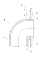
- FIG. 2 is a plan view showing a planar structure of the heat exchanger of the first embodiment.
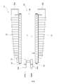
- FIG. 3 is a side view showing a side structure of the heat exchange section of the heat exchanger of the first embodiment.
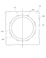
- FIG. 4 is a sectional view showing a sectional structure taken along line IV-IV in FIG.
- FIG. 5 is a figure which shows the structure which looked at the junction part of the duct plate and inflow pipe in the heat exchanger of 1st Embodiment from the lower side.
- FIG. 1 is a block diagram showing a schematic configuration of an intake system of a vehicle in which the heat exchanger of the first embodiment is used.
- FIG. 2 is a plan view showing a planar structure of the heat exchanger of the first embodiment.
- FIG. 3 is a side view showing a side structure of the heat exchange section of the heat exchanger of the first embodiment.
- FIG. 6 is a cross-sectional view showing a part of a process of joining the duct plate and the inflow pipe in the heat exchanger of the first embodiment.
- 7: is a figure which shows the structure which looked at the junction part of the duct plate and inflow pipe in the heat exchanger of FIG. 6 from the lower side.
- FIG. 8 is a cross-sectional view showing an example of the flow of the brazing material around the joint between the insertion hole of the duct plate and the inflow pipe in the heat exchanger of the first embodiment.
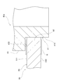
- FIG. 9 is a cross-sectional view showing the cross-sectional structure around the joint between the insertion hole of the duct plate and the inflow pipe in the heat exchanger of the first embodiment.
- FIG. 10 is a cross-sectional view showing a cross-sectional structure around a joint portion between the insertion hole of the duct plate and the inflow pipe in the heat exchanger of the first modified example of the first embodiment.
- FIG. 11 is a cross-sectional view showing a cross-sectional structure around the joint between the insertion hole of the duct plate and the inflow pipe in the heat exchanger of the second modification of the first embodiment.
- FIG. 12 is a cross-sectional view showing the cross-sectional structure around the joint between the insertion hole of the duct plate and the inflow pipe in the heat exchanger of the third modification of the first embodiment.
- FIG. 13 is a cross-sectional view showing the cross-sectional structure around the joint between the insertion hole of the duct plate and the inflow pipe in the heat exchanger of the second embodiment.
- FIG. 14 is a figure which shows the structure which looked at the joining part of the inflow pipe and the insertion hole of the duct plate in the heat exchanger of 3rd Embodiment from the lower side.
- FIG. 15 is a figure which shows a part of joining process of the duct plate and inflow pipe in the heat exchanger of 3rd Embodiment.
- FIG. 16 is a figure which shows a part of joining process of the duct plate and inflow pipe in the heat exchanger of 3rd Embodiment.
- the intake system 10 of the vehicle is provided with a supercharger 12 that supercharges the air taken into the engine 11.
- a heat exchanger 13 is provided between the engine 11 and the supercharger 12.
- the heat exchanger 13 cools the supercharged air and supplies it to the engine 11 by exchanging heat between the cooling water and the air supercharged by the supercharger 12.
- the efficiency of filling the air supplied to the engine 11 is improved, so that the output of the engine 11 can be increased.
- the supercharged air corresponds to the first fluid
- the cooling water corresponds to the second fluid.
- the heat exchanger 13 includes a heat exchange section 20, tanks 30 and 31, and pipes 40a and 40b.
- the heat exchanger 13 is made of a metal material such as an aluminum alloy.
- the heat exchange section 20 is formed in a substantially rectangular parallelepiped shape.
- the heat exchange section 20 includes a duct plate 50, an inflow side caulking plate 52, and an outflow side caulking plate 53.
- the duct plate 50 corresponds to the plate material.
- the duct plate 50 is formed in a rectangular tube shape.
- An inflow side caulking plate 52 formed in a square ring shape is joined by brazing to the peripheral edge of the opening at one end of the duct plate 50.
- a square tubular opening formed at one end of the inflow tank 30 is caulked and fixed to the inflow side caulking plate 52.
- An outflow side caulking plate 53 formed in a square ring shape is joined to the peripheral edge of the opening at the other end of the duct plate 50 by brazing.
- On the outflow side caulking plate 53, a square tubular opening formed at one end of the outflow side tank 31 is caulked and fixed.
- the outer wall portion 51 of the duct plate 50 is provided with an inflow pipe 40a into which cooling water flows and a discharge pipe 40b from which cooling water is discharged.
- the supercharged air flows into the inflow side tank 30 through the pipe connected to the other end 30a of the inflow side tank 30.
- the supercharged air that has flowed into the other end 30a of the inflow side tank 30 passes through the inflow side tank 30 and flows inside the duct plate 50 in the direction indicated by the arrow Y in the figure.
- the supercharged air that has passed through the duct plate 50 flows through the inside of the outflow side tank 31 and is discharged to the pipe connected to the other end 31 a of the outflow side tank 31.
- the heat exchange section 20 further includes a heat exchange core section 60 housed inside the duct plate 50.
- the heat exchange core part 60 is a part where heat is actually exchanged between the supercharged air and the cooling water.
- the heat exchange core portion 60 has a plurality of cooling plates 61 and a plurality of outer fins 62.
- a plurality of cooling plates 61 are laminated and arranged at a predetermined interval. Each cooling plate 61 is configured by joining a pair of plate members in the middle. The internal space of each cooling plate 61 is a cooling water flow path through which cooling water flows. The cooling water flow paths of each cooling plate 61 are in communication with each other. The cooling water flow path of each cooling plate 61 communicates with the inflow pipe 40a and the discharge pipe 40b shown in FIG. A gap is formed between the adjacent cooling plates 61, 61, through which the supercharged air flowing through the duct plate 50 passes.
- the outer fin 62 is arranged in the gap between the adjacent cooling plates 61, 61.
- the outer fin 62 has a function of increasing the heat transfer performance of the heat exchanger 13 by increasing the heat transfer area of the cooling plate 61 with respect to the supercharged air.
- the cooling water flowing into the inflow pipe 40 a is distributed to the cooling water flow passages inside each cooling plate 61.
- the heat of the supercharging air is cooled by exchanging heat between the supercharging air flowing outside the cooling plate 61 and the cooling water. Absorbed by water. As a result, the supercharged air is cooled.
- the cooling water whose temperature has risen by absorbing the heat of the supercharged air is discharged to the outside through the discharge pipe 40b.
- the structure of the joint portion between the duct plate 50 and the pipes 40a and 40b will be specifically described. Since the structure of the joint between the duct plate 50 and the exhaust pipe 40b is the same as the structure of the joint between the duct plate 50 and the inflow pipe 40a, the connection between the duct plate 50 and the inflow pipe 40a will be described below. The structure will be described as a representative.
- an insertion hole 54 into which the inflow pipe 40a is inserted is formed in the outer wall portion 51 of the duct plate 50.
- the insertion hole 54 has a shape in which burring is not formed.
- An inner surface 510 which is one surface of the outer wall portion 51 of the duct plate 50, is coated with a brazing material.
- the outer surface 511 of the outer wall portion 51 of the duct plate 50 which is the surface opposite to the inner surface 510, is not covered with the brazing material.
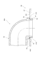
- the inflow pipe 40a is formed in a substantially L shape, and has a first portion 41 formed to extend in a direction orthogonal to the outer surface 511 of the outer wall portion 51 of the duct plate 50, and a tip of the first portion 41. And a second portion 42 formed so as to extend parallel to the outer surface 511 of the outer wall portion 51 of the duct plate 50.
- the end portion 410 of the first portion 41 of the inflow pipe 40a is widened over the entire circumference. As a result, the outer peripheral portion of the end portion 410 of the inflow pipe 40a is caulked to the inner peripheral surface of the insertion hole 54 of the duct plate 50 over the entire circumference.
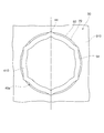
- brazing filler metal passages 80 each having a notch having a semicircular cross section are formed on the inner peripheral surface of the insertion hole 54 of the duct plate 50.
- the brazing material flow channel 80 is formed so as to extend from the inner surface 510 of the outer wall portion 51 of the duct plate 50 shown in FIG. 4 to the outer surface 511.
- the brazing filler metal flow channel 80 is Not blocked. Therefore, the brazing material coated on the inner surface 510 of the duct plate 50 can flow to the outer surface 511 of the outer wall portion 51 of the duct plate 50 shown in FIG. 4 through the brazing material flow path 80.
- a gap is formed between the outer peripheral surface of the end portion 410 of the inflow pipe 40 a and the inner peripheral surface of the insertion hole 54 of the duct plate 50.
- the brazing filler metal 70 flows in and is filled.
- the brazing material 70 joins the inflow pipe 40 a and the duct plate 50.
- a protrusion 43 is formed on the first portion 41 of the inflow pipe 40a so as to protrude from the outer peripheral portion thereof.
- the protruding portion 43 is formed at a portion of the outer peripheral portion of the first portion 41 of the inflow pipe 40a corresponding to the extending direction of the second portion 42.
- the brazing filler metal 70 flows and is filled through the brazing filler metal flow channel 80.
- the brazing material 70 joins the inflow pipe 40 a to the duct plate 50.
- the end portion 410 of the inflow pipe 40 a is inserted into the insertion hole 54 of the duct plate 50 in the assembly process in which the components of the heat exchanger 13 are assembled.
- the bottom surface 430 of the protruding portion 43 of the inflow pipe 40 a contacts the outer surface 511 of the outer wall portion 51 of the duct plate 50, so that the second portion 42 of the inflow pipe 40 a with respect to the outer surface 511 of the outer wall portion 51 of the duct plate 50.
- the position is defined.
- the protrusion 43 of the inflow pipe 40a functions as a positioning portion.
- the end portion 410 of the inflow pipe 40a is widened, so that the outer peripheral portion of the end portion 410 of the inflow pipe 40a is entirely covered with the inner portion of the insertion hole 54 of the duct plate 50 as shown in FIG. It is crimped on the circumference. As a result, the inflow pipe 40a is temporarily fixed to the duct plate 50.
- a joining process for joining the parts of the heat exchanger 13 by brazing is performed.
- the joining step first, an appropriate jig is attached to an assembly of each component to hold each component in an assembled state. After that, the assembly to which the jig is attached is put into a furnace to heat each component, thereby melting the brazing material coated on the surface of each component. As a result, the brazing material penetrates into the joints of the parts.
- the brazing material coated on the inner surface 510 of the outer wall portion 51 of the duct plate 50 flows into the brazing material channel 80.
- the brazing filler metal that has flowed into the brazing filler metal flow passage 80 has a gap formed between the outer peripheral surface of the end portion 410 of the inflow pipe 40a and the inner peripheral surface of the insertion hole 54 of the duct plate 50, and the protruding portion of the inflow pipe 40a. It flows into the gap formed between the bottom surface 430 of 43 and the outer surface 511 of the outer wall portion 51 of the duct plate 50 by a capillary phenomenon.
- the assembly taken out of the furnace is cooled by natural cooling or the like, so that the parts of the heat exchanger 13 are joined.
- the brazing material 70 that has flowed into the flow path 80 is solidified.
- the brazing material 70 that has flowed into the gap formed between the outer peripheral surface of the end portion 410 of the inflow pipe 40a and the inner peripheral surface of the insertion hole 54 of the duct plate 50 also solidifies.
- the inflow pipe 40a and the duct plate 50 are joined by the brazing material 70.
- the heat exchanger 13 has a duct plate 50 having one surface coated with a brazing material and the opposite surface not coated with the brazing material, and an inflow pipe 40a on the side of the duct plate 50 not coated with the brazing material. It has a configuration in which the protruding portion 43 having a fixed shape is installed.
- the heat exchanger 13 has a brazing filler metal flow channel 80 formed so as to penetrate the inner surface 510 which is the brazing filler metal surface and the outer surface 511 which is the non-brazing filler metal surface of the duct plate 50.
- the brazing material flow path 80 is formed between the inner peripheral surface of the insertion hole 54 of the duct plate 50 and the outer peripheral surface of the inflow pipe 40a.
- the brazing material flow passage 80 is formed so as to extend from the inner surface 510 of the outer wall portion 51 of the duct plate 50 to the outer surface 511.
- the brazing material coated on the inner surface 510 of the outer wall portion 51 of the duct plate 50 flows into the brazing material channel 80.
- brazing material 70 is coated on the inner surface 510 of the outer wall portion 51 of the duct plate 50, a jig used for brazing each component of the heat exchanger 13 does not come into contact with the brazing material. Therefore, it is possible to reduce the occurrence of appearance defects.
- the brazing material flow passage 80 is formed on the inner peripheral surface of the insertion hole 54 of the duct plate 50. With such a configuration, the brazing filler metal flow path 80 can be easily formed only by processing the inner peripheral surface of the insertion hole 54 of the duct plate 50.
- the flow passage width H1 of the brazing filler metal flow passage 80 is equal to the gap formed between the inner peripheral surface of the insertion hole 54 of the duct plate 50 and the outer peripheral surface of the inflow pipe 40a. It is larger than the width H2. With such a configuration, the brazing material can easily flow into the brazing material channel 80.
- the entire outer peripheral surface of the inflow pipe 40 a is crimped to the inner peripheral surface of the insertion hole 54 of the duct plate 50.
- the brazing material flow passage 80 is formed on the inner peripheral surface of the insertion hole 54 of the duct plate 50.
- the protrusion 43 of the inflow pipe 40a has a bottom surface 430 in contact with the outer surface 511 of the outer wall portion 51 of the duct plate 50, so that the second portion of the inflow pipe 40a relative to the outer surface 511 of the outer wall portion 51 of the duct plate 50. It functions as a positioning unit that defines the position of 42. With such a configuration, the position of the second portion 42 of the inflow pipe 40a with respect to the outer surface 511 of the outer wall portion 51 of the duct plate 50 can be easily defined.
- the spacer member 90 defines the position of the second portion 42 of the inflow pipe 40a with respect to the outer surface 511 of the outer wall portion 51 of the duct plate 50. That is, in this embodiment, the spacer member 90 functions as the fixed shape and the positioning portion of the inflow pipe 40a.
- the action and effect shown in the following (6) can be obtained as the action and the effect in place of the above (5).
- the spacer member 90 can easily define the position of the second portion 42 of the inflow pipe 40a with respect to the outer surface 511 of the outer wall portion 51 of the duct plate 50. Further, compared to the case where the protrusion 43 is formed on the inflow pipe 40a, it is possible to avoid complication of the structure of the inflow pipe 40a.
- the spacer member 90 a double-sided clad, the duct outer surface 511 and the lower surface of the second portion 42 of the inflow pipe 40a can be brazed via the spacer member 90, and the brazing strength of the pipe can also be increased. Become.
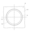
- FIG. 14 a part of the end portion 410 of the inflow pipe 40a of the present embodiment is diverged outward in the radial direction.
- the end portion 410 of the inflow pipe 40a is formed with a plurality of protruding portions 44 protruding outward in the radial direction.
- the plurality of protrusions 44 are caulked on the inner peripheral surface of the insertion hole 54 of the duct plate 50.
- a gap is formed between the outer peripheral surface of the end portion 410 of the inflow pipe 40a where the protrusion 44 is not formed and the inner peripheral surface of the insertion hole 54 of the duct plate 50.
- This gap serves as a brazing filler metal flow channel 80 into which the brazing filler metal coated on the inner surface 510 of the outer wall portion 51 of the duct plate 50 flows.
- the inflow pipe 40a and the duct plate 50 are joined by the brazing filler metal 70 filled in the brazing filler metal flow passage 80.
- the action and effect shown in the following (6) can be obtained as the action and effect in place of the above (4).
- (6) Since a part of the outer peripheral surface of the inflow pipe 40a is caulked to the inner peripheral surface of the insertion hole 54 of the duct plate 50, the inflow pipe 40a can be temporarily fixed to the duct plate 50. ..
- the brazing filler metal flow path 80 is provided between a portion of the outer peripheral surface of the inflow pipe 40a that is not crimped on the inner peripheral surface of the insertion hole 54 of the duct plate 50 and the inner peripheral surface of the insertion hole 54 of the duct plate 50. It is formed by the gap formed. Therefore, it is possible to flow the brazing material through the brazing material flow path 80 to the joint portion between the inflow pipe 40a and the duct plate 50 through the brazing material flow path 80.
- the above-mentioned embodiment can also be implemented in the following forms.
- the number of brazing filler metal passages 80 formed for one inflow pipe 40a can be changed as appropriate.
- the number of brazing filler metal flow paths 80 formed for one inflow pipe 40a may be at least one.
- the brazing material flow path 80 is not limited to the inner peripheral surface of the insertion hole 54 of the duct plate 50, and may be formed on the outer peripheral surface of the inflow pipe 40a. Alternatively, the brazing material flow path 80 may be formed on both the inner peripheral surface of the insertion hole 54 of the duct plate 50 and the outer peripheral surface of the inflow pipe 40a.
- the first fluid flowing through the duct plate 50 is not limited to the supercharged air, and an appropriate fluid can be used.
- the second fluid flowing through the cooling plate 61 is not limited to cooling water, but an appropriate fluid can be used.
- the present disclosure is not limited to the above specific examples. A person skilled in the art appropriately modified the above-described specific examples is also included in the scope of the present disclosure as long as the features of the present disclosure are provided.
- the elements included in the above-described specific examples, and the arrangement, conditions, shapes, and the like of the elements are not limited to those illustrated, but can be appropriately changed.
- the respective elements included in the above-described specific examples can be appropriately combined as long as there is no technical contradiction.
Landscapes
- Engineering & Computer Science (AREA)
- Mechanical Engineering (AREA)
- Physics & Mathematics (AREA)
- Thermal Sciences (AREA)
- General Engineering & Computer Science (AREA)
- Heat-Exchange Devices With Radiators And Conduit Assemblies (AREA)
- Details Of Heat-Exchange And Heat-Transfer (AREA)
Abstract
Cette invention concerne un échangeur de chaleur comprenant un matériau de plaque (50) de telle sorte qu'une première surface est revêtue d'un matériau de brasage et une surface opposée à la première surface n'est pas revêtue d'un matériau de brasage. Un tube (40a) est installé, de façon à avoir une forme fixe, sur le côté du matériau de plaque sur lequel le matériau de brasage n'est pas déposé. L'échangeur de chaleur comprend un trajet d'écoulement de matériau de brasage (80) formé de façon à pénétrer la surface de matériau de brasage du matériau de plaque et la surface de matériau sans brasage de celui-ci. Le matériau de brasage qui a été déposé sur le matériau de plaque s'écoule dans le trajet d'écoulement de matériau de brasage.
Priority Applications (2)
| Application Number | Priority Date | Filing Date | Title |
|---|---|---|---|
| CN201980076499.5A CN113167553A (zh) | 2018-11-20 | 2019-11-06 | 热交换器 |
| US17/322,551 US20210270548A1 (en) | 2018-11-20 | 2021-05-17 | Heat exchanger |
Applications Claiming Priority (2)
| Application Number | Priority Date | Filing Date | Title |
|---|---|---|---|
| JP2018-217485 | 2018-11-20 | ||
| JP2018217485A JP2020085288A (ja) | 2018-11-20 | 2018-11-20 | 熱交換器 |
Related Child Applications (1)
| Application Number | Title | Priority Date | Filing Date |
|---|---|---|---|
| US17/322,551 Continuation US20210270548A1 (en) | 2018-11-20 | 2021-05-17 | Heat exchanger |
Publications (1)
| Publication Number | Publication Date |
|---|---|
| WO2020105435A1 true WO2020105435A1 (fr) | 2020-05-28 |
Family
ID=70774443
Family Applications (1)
| Application Number | Title | Priority Date | Filing Date |
|---|---|---|---|
| PCT/JP2019/043485 WO2020105435A1 (fr) | 2018-11-20 | 2019-11-06 | Échangeur de chaleur |
Country Status (4)
| Country | Link |
|---|---|
| US (1) | US20210270548A1 (fr) |
| JP (1) | JP2020085288A (fr) |
| CN (1) | CN113167553A (fr) |
| WO (1) | WO2020105435A1 (fr) |
Citations (10)
| Publication number | Priority date | Publication date | Assignee | Title |
|---|---|---|---|---|
| JPS5623874U (fr) * | 1979-07-26 | 1981-03-04 | ||
| JPS6234964U (fr) * | 1985-08-22 | 1987-03-02 | ||
| JPS62142683U (fr) * | 1986-02-27 | 1987-09-09 | ||
| JPS635294U (fr) * | 1986-06-26 | 1988-01-14 | ||
| JPH08327280A (ja) * | 1995-05-30 | 1996-12-13 | Sanden Corp | 熱交換器の流体給排管接合構造 |
| JPH11281289A (ja) * | 1998-03-31 | 1999-10-15 | Calsonic Corp | 熱交換器用タンク |
| JPH11281292A (ja) * | 1998-03-30 | 1999-10-15 | Denso Corp | 積層型熱交換器 |
| JP2005172270A (ja) * | 2003-12-08 | 2005-06-30 | Calsonic Kansei Corp | オイルクーラ内蔵ラジエータ |
| JP2018136064A (ja) * | 2017-02-21 | 2018-08-30 | 株式会社デンソー | 熱交換器 |
| JP2019116985A (ja) * | 2017-12-26 | 2019-07-18 | 株式会社ノーリツ | 熱交換器の製造方法、熱交換器中間品、および熱交換器 |
Family Cites Families (40)
| Publication number | Priority date | Publication date | Assignee | Title |
|---|---|---|---|---|
| US2217000A (en) * | 1937-11-26 | 1940-10-08 | Universal Oil Prod Co | Fluid conduit |
| US2195403A (en) * | 1939-04-14 | 1940-04-02 | Thomas J Bay | Condenser tube protector |
| US2225615A (en) * | 1940-01-08 | 1940-12-24 | Thomas J Bay | Condenser tube protector |
| US2620830A (en) * | 1950-02-18 | 1952-12-09 | Schultz Herman | Self-sealing tube insert |
| US3317222A (en) * | 1964-04-16 | 1967-05-02 | Cons Edison Co New York Inc | Insert constructions for tubes of heat exchangers and condensers |
| US3349465A (en) * | 1965-05-14 | 1967-10-31 | United Aircraft Corp | Tube-to-sheet joint making |
| US3400755A (en) * | 1967-02-02 | 1968-09-10 | Ingersoll Rand Co | Method and article for protecting condenser tubes |
| US3844588A (en) * | 1972-06-21 | 1974-10-29 | Ingersoll Rand Co | Condenser tube support plate insert |
| US3857151A (en) * | 1973-10-15 | 1974-12-31 | Young Radiation Co | Method of making a radiator core |
| JPS5157488A (ja) * | 1974-11-14 | 1976-05-19 | Shimadzu Corp | Riikutesutohoho |
| GB1591842A (en) * | 1977-02-11 | 1981-06-24 | Serck Industries Ltd | Method of and apparatus for joining a tubular element to a support |
| JPS57144895A (en) * | 1981-03-04 | 1982-09-07 | Hitachi Ltd | Fin and tube type of heat exchanger |
| US4528733A (en) * | 1983-07-25 | 1985-07-16 | United Aircraft Products, Inc. | Method of making tubular heat exchangers |
| JPS6317395A (ja) * | 1986-07-09 | 1988-01-25 | Hitachi Ltd | 管と管板の接合構造 |
| JPH069738Y2 (ja) * | 1987-01-23 | 1994-03-16 | 株式会社ゼクセル | 管材のろう付け構造 |
| US4941512A (en) * | 1988-11-14 | 1990-07-17 | Cti Industries, Inc. | Method of repairing heat exchanger tube ends |
| CN1162109A (zh) * | 1995-05-30 | 1997-10-15 | 三电有限公司 | 热交换器及其制造方法 |
| CN1153690A (zh) * | 1996-01-05 | 1997-07-09 | 黄月义 | 具有金属渗层的管子与管板间的焊接方法及焊接材料 |
| JP3808578B2 (ja) * | 1997-02-21 | 2006-08-16 | カルソニックカンセイ株式会社 | 熱交換器用タンクへのパイプ取付構造 |
| JP3054939B2 (ja) * | 1997-03-31 | 2000-06-19 | 株式会社ゼクセル | 積層型熱交換器 |
| KR19980080427A (ko) * | 1997-04-09 | 1998-11-25 | 다카노야스아키 | 흡수식 냉동기 |
| DE19719259B4 (de) * | 1997-05-07 | 2005-08-18 | Valeo Klimatechnik Gmbh & Co. Kg | Flachrohrwärmetauscher für Kraftfahrzeuge mit an Krägen eines Rohrbodens gehaltenen Flachrohren |
| JPH1151591A (ja) * | 1997-08-01 | 1999-02-26 | Calsonic Corp | 積層型熱交換器 |
| US6138747A (en) * | 1999-02-17 | 2000-10-31 | Dehr Heat Transfer System, Inc. | Heat exchanger tube to header swaging process |
| JP4588933B2 (ja) * | 2001-07-10 | 2010-12-01 | 株式会社ティラド | 樹脂製パイプとタンクとの接続構造 |
| DE50306374D1 (de) * | 2003-05-20 | 2007-03-15 | Behr France Rouffach Sas | Rohranschlussverbindung für Wärmeübertrager, insbesondere Heinzkörper für Kraftfahrzeuge |
| JP2005121350A (ja) * | 2003-05-29 | 2005-05-12 | Denso Corp | 熱交換器およびその製造方法 |
| DE10343634A1 (de) * | 2003-09-20 | 2005-04-14 | Modine Manufacturing Co., Racine | Wärmeaustauscher für Kraftfahrzeuge |
| US7380327B2 (en) * | 2005-01-20 | 2008-06-03 | Calsonickansei North America, Inc. | Tube interface and method of securing a first tube to a second tube |
| JP5741931B2 (ja) * | 2011-05-31 | 2015-07-01 | 株式会社ノーリツ | 熱交換器 |
| JP6124044B2 (ja) * | 2011-07-20 | 2017-05-10 | 京進工業株式会社 | 熱交換器挿通管の掴持体の製造方法 |
| KR20140011182A (ko) * | 2012-07-18 | 2014-01-28 | 김영진 | 알루미늄 열교환기 |
| DE102012108821B4 (de) * | 2012-09-19 | 2014-08-14 | Benteler Automobiltechnik Gmbh | Verfahren zur Herstellung eines Wärmetauschers |
| WO2014076949A1 (fr) * | 2012-11-14 | 2014-05-22 | パナソニック株式会社 | Ensemble tube d'alliage d'aluminium et échangeur de chaleur l'utilisant |
| KR20150053135A (ko) * | 2013-11-07 | 2015-05-15 | 엘지전자 주식회사 | 열교환기 및 그 제조방법 |
| CN206001968U (zh) * | 2014-04-21 | 2017-03-08 | 三菱电机株式会社 | 集管分配器、热交换器以及空调装置 |
| JP6587098B2 (ja) * | 2015-10-29 | 2019-10-09 | パナソニックIpマネジメント株式会社 | 熱交換器アルミニウム管ろう付け用ろう材、並びに、これを用いた熱交換器アルミニウム管の接合方法および熱交換器アルミニウム管の接合構造 |
| CN109477703B (zh) * | 2016-08-08 | 2020-08-07 | 三菱电机株式会社 | 层叠型集管以及层叠型集管的制造方法 |
| EP3499171A1 (fr) * | 2017-12-15 | 2019-06-19 | ALFA LAVAL OLMI S.p.A. | Dispositif anti-érosion pour équipement à faisceau tubulaire |
| JP7293570B2 (ja) * | 2019-03-25 | 2023-06-20 | 株式会社ノーリツ | 熱交換器およびその製造方法 |
-
2018
- 2018-11-20 JP JP2018217485A patent/JP2020085288A/ja active Pending
-
2019
- 2019-11-06 CN CN201980076499.5A patent/CN113167553A/zh active Pending
- 2019-11-06 WO PCT/JP2019/043485 patent/WO2020105435A1/fr active Application Filing
-
2021
- 2021-05-17 US US17/322,551 patent/US20210270548A1/en not_active Abandoned
Patent Citations (10)
| Publication number | Priority date | Publication date | Assignee | Title |
|---|---|---|---|---|
| JPS5623874U (fr) * | 1979-07-26 | 1981-03-04 | ||
| JPS6234964U (fr) * | 1985-08-22 | 1987-03-02 | ||
| JPS62142683U (fr) * | 1986-02-27 | 1987-09-09 | ||
| JPS635294U (fr) * | 1986-06-26 | 1988-01-14 | ||
| JPH08327280A (ja) * | 1995-05-30 | 1996-12-13 | Sanden Corp | 熱交換器の流体給排管接合構造 |
| JPH11281292A (ja) * | 1998-03-30 | 1999-10-15 | Denso Corp | 積層型熱交換器 |
| JPH11281289A (ja) * | 1998-03-31 | 1999-10-15 | Calsonic Corp | 熱交換器用タンク |
| JP2005172270A (ja) * | 2003-12-08 | 2005-06-30 | Calsonic Kansei Corp | オイルクーラ内蔵ラジエータ |
| JP2018136064A (ja) * | 2017-02-21 | 2018-08-30 | 株式会社デンソー | 熱交換器 |
| JP2019116985A (ja) * | 2017-12-26 | 2019-07-18 | 株式会社ノーリツ | 熱交換器の製造方法、熱交換器中間品、および熱交換器 |
Also Published As
| Publication number | Publication date |
|---|---|
| CN113167553A (zh) | 2021-07-23 |
| JP2020085288A (ja) | 2020-06-04 |
| US20210270548A1 (en) | 2021-09-02 |
Similar Documents
| Publication | Publication Date | Title |
|---|---|---|
| JP2001099585A (ja) | アルミニウム製熱交換器 | |
| JP6197338B2 (ja) | 熱交換器 | |
| WO1999026037A1 (fr) | Echangeur thermique | |
| US11143457B2 (en) | Heat exchanger | |
| US20070000652A1 (en) | Heat exchanger with dimpled tube surfaces | |
| JP2007212084A (ja) | 熱交換器 | |
| US7322403B2 (en) | Heat exchanger with modified tube surface feature | |
| JP2007051576A (ja) | Egrクーラ | |
| JPH0989491A (ja) | Egrガス冷却装置 | |
| JP2018128183A (ja) | 熱交換器 | |
| JP2016070655A (ja) | 熱交換器 | |
| WO2020105435A1 (fr) | Échangeur de chaleur | |
| JP2003106790A (ja) | 排気熱交換器 | |
| JP4713211B2 (ja) | 熱交換器 | |
| JP2012159211A (ja) | 熱交換器 | |
| JP4787511B2 (ja) | 熱交換器の接合構造及びその接合方法 | |
| JP4085402B2 (ja) | オイルクーラとラジエータタンクとの接合方法 | |
| JP5359288B2 (ja) | 熱交換器 | |
| JPH09280774A (ja) | 熱交換器 | |
| KR20090029861A (ko) | 오일쿨러 및 라디에이터 조립체, 및 그 제조방법 | |
| JP2020003089A (ja) | 熱交換チューブ及び熱交換器 | |
| JP2006234318A (ja) | 熱交換器 | |
| JP2018204578A (ja) | 熱交換器 | |
| JPH11337292A (ja) | 熱交換器 | |
| JPH09250888A (ja) | 2重管式熱交換器 |
Legal Events
| Date | Code | Title | Description |
|---|---|---|---|
| 121 | Ep: the epo has been informed by wipo that ep was designated in this application |
Ref document number: 19886892 Country of ref document: EP Kind code of ref document: A1 |
|
| NENP | Non-entry into the national phase |
Ref country code: DE |
|
| 122 | Ep: pct application non-entry in european phase |
Ref document number: 19886892 Country of ref document: EP Kind code of ref document: A1 |