WO2020049960A1 - 搬送車 - Google Patents
搬送車 Download PDFInfo
- Publication number
- WO2020049960A1 WO2020049960A1 PCT/JP2019/031756 JP2019031756W WO2020049960A1 WO 2020049960 A1 WO2020049960 A1 WO 2020049960A1 JP 2019031756 W JP2019031756 W JP 2019031756W WO 2020049960 A1 WO2020049960 A1 WO 2020049960A1
- Authority
- WO
- WIPO (PCT)
- Prior art keywords
- frame
- body frames
- pair
- lifter
- carrier according
- Prior art date
Links
Images


Classifications
-
- B—PERFORMING OPERATIONS; TRANSPORTING
- B60—VEHICLES IN GENERAL
- B60P—VEHICLES ADAPTED FOR LOAD TRANSPORTATION OR TO TRANSPORT, TO CARRY, OR TO COMPRISE SPECIAL LOADS OR OBJECTS
- B60P1/00—Vehicles predominantly for transporting loads and modified to facilitate loading, consolidating the load, or unloading
- B60P1/02—Vehicles predominantly for transporting loads and modified to facilitate loading, consolidating the load, or unloading with parallel up-and-down movement of load supporting or containing element
-
- B—PERFORMING OPERATIONS; TRANSPORTING
- B66—HOISTING; LIFTING; HAULING
- B66F—HOISTING, LIFTING, HAULING OR PUSHING, NOT OTHERWISE PROVIDED FOR, e.g. DEVICES WHICH APPLY A LIFTING OR PUSHING FORCE DIRECTLY TO THE SURFACE OF A LOAD
- B66F3/00—Devices, e.g. jacks, adapted for uninterrupted lifting of loads
- B66F3/02—Devices, e.g. jacks, adapted for uninterrupted lifting of loads with racks actuated by pinions
-
- B—PERFORMING OPERATIONS; TRANSPORTING
- B61—RAILWAYS
- B61B—RAILWAY SYSTEMS; EQUIPMENT THEREFOR NOT OTHERWISE PROVIDED FOR
- B61B13/00—Other railway systems
-
- B—PERFORMING OPERATIONS; TRANSPORTING
- B62—LAND VEHICLES FOR TRAVELLING OTHERWISE THAN ON RAILS
- B62B—HAND-PROPELLED VEHICLES, e.g. HAND CARTS OR PERAMBULATORS; SLEDGES
- B62B3/00—Hand carts having more than one axis carrying transport wheels; Steering devices therefor; Equipment therefor
-
- B—PERFORMING OPERATIONS; TRANSPORTING
- B62—LAND VEHICLES FOR TRAVELLING OTHERWISE THAN ON RAILS
- B62B—HAND-PROPELLED VEHICLES, e.g. HAND CARTS OR PERAMBULATORS; SLEDGES
- B62B3/00—Hand carts having more than one axis carrying transport wheels; Steering devices therefor; Equipment therefor
- B62B3/04—Hand carts having more than one axis carrying transport wheels; Steering devices therefor; Equipment therefor involving means for grappling or securing in place objects to be carried; Loading or unloading equipment
- B62B3/06—Hand carts having more than one axis carrying transport wheels; Steering devices therefor; Equipment therefor involving means for grappling or securing in place objects to be carried; Loading or unloading equipment for simply clearing the load from the ground
-
- B—PERFORMING OPERATIONS; TRANSPORTING
- B66—HOISTING; LIFTING; HAULING
- B66F—HOISTING, LIFTING, HAULING OR PUSHING, NOT OTHERWISE PROVIDED FOR, e.g. DEVICES WHICH APPLY A LIFTING OR PUSHING FORCE DIRECTLY TO THE SURFACE OF A LOAD
- B66F9/00—Devices for lifting or lowering bulky or heavy goods for loading or unloading purposes
- B66F9/06—Devices for lifting or lowering bulky or heavy goods for loading or unloading purposes movable, with their loads, on wheels or the like, e.g. fork-lift trucks
- B66F9/063—Automatically guided
Definitions
- the present invention relates to a transport vehicle, and particularly to a transport vehicle having a lifter.
- Patent Literature 1 discloses, for example, a forklift 2.
- the forklift 2 has a pair of left and right side frames 4 and 6 and a rear frame 8.
- a conventional lifter-equipped transport vehicle can lift and transport a heavy object (for example, about 1000 kg). It is necessary to reinforce the main frame in order to cope with such a large load, but the reinforcement of the main frame increases the size of the body. As the size of the body increases, the weight of the entire transport vehicle increases, and the size of the battery and motor also need to be increased. Further, in the conventional lifter-equipped transport vehicle, the main frame and the lifter frame are separately configured, so that the frame is doubled, so that there is no useless space to secure the space for the mounting portion. Had occurred.
- An object of the present invention is to reduce the size of a transporter with a lifter.
- a transport vehicle includes a pair of left and right body frames, drive wheels, auxiliary wheels, and a lifter mechanism.
- the pair of left and right body frames extend in the front-rear direction.
- the drive wheels are arranged at the center in the front-rear direction of each body frame. Therefore, the number of drive wheels is two in total.
- the auxiliary wheels are arranged at the front and rear ends and lower portions of each body frame. Therefore, the number of auxiliary wheels is four in total.
- the lifter mechanism is disposed at an end and an upper part in the front-rear direction of each body frame. Therefore, the number of lifter mechanisms is four in total.
- the place where the lifter mechanism is mounted is a frame that supports the drive wheels and the auxiliary wheels. Therefore, the lifter mechanism and the frame can be integrated, so that the carrier can be reduced in size and weight.
- the lifter mechanism and the auxiliary wheels are further provided at the front and rear ends of each body frame, the lifter mechanism is arranged near the auxiliary wheels. For this reason, a large load is less likely to act on portions other than the ends of the frame, so that the carrier can be reduced in size and weight.
- the positions of the auxiliary wheels and the lifter mechanism in plan view may be the same or different.
- the carrier may further include a connection frame and a lower frame.
- the connection frame may connect the upper portions of the pair of left and right body frames.
- the lower frame may be disposed between the pair of left and right body frames, and may be detachably fixed to lower portions of the pair of left and right body frames. In this transport vehicle, since the body frame and the lower frame have a divided structure, access to components disposed inside is facilitated.
- connection frame may connect the middle of the pair of left and right body frames in the front-rear direction.
- this carrier sufficient strength can be obtained with a frame having a simple structure.
- the entire body is easily bent because the pair of left and right body frames are connected only at the middle in the front-rear direction. Stress is distributed.
- Each of the lifter mechanisms may further include a lifting motor, a lifting transmission shaft, and a bearing.
- the elevating motor may be arranged above the vehicle body frame or the connection frame.
- the lifting transmission shaft may be moved up and down by being driven by a lifting motor.
- the bearing may support the elevating transmission shaft so as to be vertically movable. In this transport vehicle, the transport vehicle can be further miniaturized by supporting the lifting motor by the body frame or the connection frame.
- the transport vehicle may further include electrical components arranged on the upper surface of the lower frame at a position different from the connection frame in a plan view.
- electrical components arranged on the upper surface of the lower frame at a position different from the connection frame in a plan view.
- this transport vehicle by arranging the electrical components at different positions in plan view from the connection frame, at least a part of the electrical components and the connection frame can be arranged at the same height position. Can be compact.
- the lower frame may be able to separate downward as an integral member when being removed from the pair of left and right body frames.
- the lower frame and the electrical components can be separated downward from the body frame by a single operation by forming the body frame and the lower frame into a divided structure. Therefore, maintainability is improved. Further, at the time of assembling work, the process of the body frame and the process of the lower frame can be performed in parallel, so that the manufacturing period can be shortened.
- Each body frame may include a main body on which the lifter mechanism is mounted, and a reinforcing portion extending downward from the main body.
- the strength is improved while the weight is maintained by the body frame having the reinforcing portion.
- the carrier with the lifter is reduced in size.
- FIG. 2 is a schematic perspective view of the carrier according to the first embodiment.
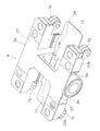
- FIG. 3 is a schematic perspective view showing a frame and a lifter mechanism of the transport vehicle.
- FIG. 4 is a schematic sectional view of a lifter mechanism.
- FIG. 3 is a schematic perspective view showing a frame of the transport vehicle. The typical perspective view which looked at the frame from the lower side.
- FIG. 2 is a schematic plan view showing a positional relationship between a frame and electrical components.
- FIG. 4 is a schematic perspective view of the lower frame assembled to the vehicle body frame as viewed from below.
- FIG. 4 is a schematic perspective view of the lower frame removed from the vehicle body frame as viewed from below.
- FIG. 1 is a schematic perspective view of the carrier according to the first embodiment.
- FIG. 2 is a schematic perspective view showing a frame and a lifter mechanism of the transport vehicle.
- FIG. 3 is a schematic sectional view of the lifter mechanism.
- the transport vehicle 1 is a device for transporting a load.
- the transport vehicle 1 can transport the load to the transfer position and move up and down. Further, the transport vehicle 1 can rotate the load about a vertical axis.
- the transport vehicle 1 includes a pair of left and right body frames 3a, 3b, drive wheels 5a, 5b, auxiliary wheels 7a, 7b, 7c, 7d, and lifter mechanisms 9a, 9b, 9c, 9d.
- a pair of left and right body frames 3a, 3b extend in the front-back direction in the first direction, and are separated from each other in the second direction orthogonal to the front-rear direction.
- the body frames 3a and 3b are formed from thin plate members.
- the drive wheels 5a and 5b are respectively arranged at the center of the body frames 3a and 3b in the first direction. Therefore, the number of drive wheels is two in total.
- the first direction which is the side on which the drive wheels 5a and 5b face, is the traveling direction.
- the transport vehicle 1 has traveling motors 8a and 8b.
- the traveling motors 8a and 8b are of a direct drive type disposed in the driving wheels 5a and 5b, respectively.
- the traveling motor 8a is hidden and does not appear in the drawing.
- the auxiliary wheels 7a, 7b, 7c, 7d are arranged at the lower end and in the first direction of the body frames 3a, 3b.
- the auxiliary wheel 7a is provided at the front end of the vehicle body frame 3a
- the auxiliary wheel 7b is provided at the rear end of the vehicle body frame 3a
- the auxiliary wheel 7c is provided at the front end of the vehicle body frame 3b
- 7d is provided at the rear end of the body frame 3b.
- the auxiliary wheel is, for example, a caster wheel, and is also rotatable around a vertical axis.
- the auxiliary wheels 7a to 7d receive most of the load and the load of the transport vehicle 1, and the load received by one of the drive wheels 5a, 5b is equal to the load received by one of the auxiliary wheels 7a to 7d. It is on the order of a fraction.
- the drive wheels 5a and 5b are respectively urged downward by springs (not shown).
- the lifter mechanisms 9a to 9d are mechanisms for raising and lowering a load. Specifically, the lifter mechanisms 9a to 9d are arranged at the ends and upper portions of the body frames 3a, 3b in the first direction. More specifically, a lifter mechanism 9a is provided at a front end of the vehicle body frame 3a, a lifter mechanism 9b is provided at a rear end of the vehicle body frame 3a, and a lifter mechanism 9c is provided at a front end of the vehicle body frame 3b. A mechanism 9d is provided at the rear end of the body frame 3b. In this embodiment, the corresponding auxiliary wheels are arranged to be shifted outward in the first direction with respect to the lifter mechanism.
- the auxiliary wheel is positioned outside the lifter mechanism because the support by the auxiliary wheel is stabilized.
- the positions of the auxiliary wheels and the lifter mechanism in plan view may be the same, or they may be shifted inward in the first direction.
- the auxiliary wheels may be arranged with respect to the lifter mechanism not in the first direction but in the second direction, and shifted in both the first direction and the second direction. The advantage of shifting the auxiliary wheel with respect to the lifter mechanism in a plan view is to secure a space in which the lifting transmission shaft of the lifter mechanism moves in the vertical direction.
- the places where the lifter mechanisms 9a to 9d are mounted are the vehicle body frames 3a and 3b that support the drive wheels 5a and 5b and the auxiliary wheels 7a to 7d. Therefore, the lifter mechanisms 9a to 9d can be integrated with the body frames 3a and 3b, and the size and weight of the carrier 1 can be reduced.
- the lifter mechanisms 9a to 9d and the auxiliary wheels 7a to 7d are further provided at the ends of the body frames 3a and 3b in the first direction, so that the lifter mechanisms 9a to 9d are connected to the auxiliary wheels 7a to 7d. In the vicinity of. For this reason, a large load is less likely to act on portions other than the end portions of the body frames 3a, 3b, so that the carrier 1 can be reduced in size and weight.
- the carrier 1 further includes a connection frame 11.
- the connection frame 11 is a thin plate member, and connects upper portions of a pair of left and right body frames 3a, 3b. Specifically, as shown in FIGS. 4 and 5, the connection frame 11 has a thin plate portion 11a extending in the second direction and continuing to the upper surfaces of the pair of left and right body frames 3a, 3b.
- the connection frame 11 has, in addition to the thin plate portion 11a, other members that reinforce the connection between the pair of left and right body frames 3a, 3b.
- the connection frame 11 further has a pair of ribs 11b.
- the pair of ribs 11b are thin plate members that are fixed to lower portions at both ends in the first direction of the thin plate portion 11a and extend in the second direction.
- connection frame 11 has a reinforcing member 11c.
- the reinforcing member 11c is disposed between the pair of ribs 11b at a lower portion of both ends of the thin plate portion 11a in the second direction.
- the reinforcing member 11c is fixed to the thin plate portion 11a and the pair of ribs 11b, and is further fixed to the first reinforcing portion 29.
- the H-shaped upper frame 4 is formed by the pair of left and right body frames 3a and 3b and the connection frame 11.
- the portion where the connection frame 11 is connected is the middle of the pair of left and right body frames 3a and 3b in the first direction. Therefore, in the carrier 1, sufficient strength can be obtained with a frame having a simple structure. In particular, even if a large force is applied partially when the transport vehicle 1 passes through unevenness on the floor, the entire body bends because the pair of left and right body frames 3a and 3b are connected only at the middle in the first direction. The stress is dispersed. Further, since the lifter mechanisms 9a to 9d are provided at the four corners (the corners or corners of the H-shaped upper frame 4) in plan view of the carrier 1, a large size is provided between the pair of left and right body frames 3a, 3b. Space is secured. For this reason, the arrangement of the electrical component 17 described later is facilitated.
- the transport vehicle 1 has lifting motors 21a and 21b as a part of the lifter mechanism or a device for driving the lifter mechanism.
- the elevating motors 21 a and 21 b are provided on the connection frame 11.
- the transport vehicle 1 has distribution mechanisms 22a and 22b that distribute the power of the elevating motors 21a and 21b in two directions.
- the transport vehicle 1 has drive shafts 24a and 24b extending from the distribution mechanism 22a toward the lifter mechanisms 9a and 9b, respectively.
- the drive shafts 24a and 24b are rotatably supported by bearings 32a and 32b provided on the upper surface of the body frame 3a.
- the transport vehicle 1 has drive shafts 24c and 24d extending from the distribution mechanism 22b toward the lifter mechanisms 9c and 9d, respectively.
- the drive shafts 24c and 24d are rotatably supported by bearings 32c and 32d provided on the upper surface of the body frame 3a.
- the lifter mechanism 9a has a lifting transmission shaft 23.
- the lifting transmission shaft 23 is a member that moves up and down, and extends vertically in the vertical direction.
- the lifting transmission shaft 23 has a flat plate portion 23a on the upper part.
- the lifting transmission shaft 23 is supported by a bearing 25 supported by a housing 26 of the lifter mechanism 9a so as to be vertically movable and non-rotatably.
- the lifting transmission shaft 23 has a rack 28 on the side surface extending vertically.
- the drive shaft 24a has a pinion 30 that meshes with the rack 28.
- the elevating motor 21a rotates, as a result, the elevating transmission shaft 23 moves up and down.
- the lift motors 21a and 21b are also supported by the upper frame 4, so that the transport vehicle 1 can be further reduced in size.
- the carrier 1 has a lower frame 13.
- the lower frame 13 is disposed between the pair of left and right body frames 3a, 3b, and is detachably fixed to the lower portion of the pair of left and right body frames 3a, 3b.
- the lower frame 13 is a flat rectangular thin plate member, and is fixed to the inside of the vehicle body frames 3a, 3b in the second direction by screws (not shown).
- the vehicle body frames 3 a and 3 b and the lower frame 13 have a divided structure, so that access to the electrical components 17 described later is facilitated.
- the transport vehicle 1 further includes an electrical component 17.
- the electrical component 17 is arranged on the upper surface of the lower frame 13 at a position different from the connection frame 11 in a plan view.
- the electrical component 17 is, for example, a battery, a motor driver, or the like.
- the carrier 1 has a turning table 41.
- the swivel table 41 is a device that rotates a load (not shown) around a vertical axis.
- the turning table 41 is provided above the lifter mechanisms 9a to 9d.
- FIG. 4 is a schematic perspective view showing a frame of the carrier.
- FIG. 5 is a schematic perspective view of the frame as viewed from below.
- Each of the vehicle body frames 3a and 3b has a main body 27 having a horizontal surface and extending in the front-rear direction, and a first reinforcing portion 29 extending downward from the main body 27.
- the strength is improved while maintaining a light weight.
- the first reinforcing portion 29 is a thin plate member functioning as a rib, and extends downward from substantially the entire inner edge of the main body 27 in the second direction.
- the lower frame 13 is fixed to a lower edge of the first reinforcing portion 29.
- the body frames 3a and 3b have second reinforcing portions 31a and 31b, respectively.
- the second reinforcing portions 31a, 31b are thin plate members functioning as ribs, and are located on the lower side of the body frames 3a, 3b in the first direction inside and close to the portions where the lifter mechanisms 9a to 9d are provided. It is provided in.
- the second reinforcing portions 31a and 31b extend downward from the main body portion 27 and extend from the first reinforcing portion 29 to an edge on the opposite side in the second direction.
- the body frames 3a, 3b have third reinforcing portions 33a, 33b.
- the third reinforcing portions 33a, 33b are thin plate members functioning as ribs, and are located on the lower side of the vehicle body frames 3a, 3b outside and in the second direction with respect to the portions where the lifter mechanisms 9a to 9d are provided. It is provided in.
- the second reinforcing portions 31a, 31b extend downward from the main body 27, and extend outward in the first direction from outer edges of the second reinforcing portions 31a, 31b in the second direction.
- the first reinforcing portion 29, the second reinforcing portion 31a, and the third reinforcing portion 33a are provided so as to surround a portion where the lifter mechanisms 9a to 9d are arranged. Therefore, the rigidity around the lifter mechanisms 9a to 9d in the body frames 3a and 3b is high.
- FIG. 6 is a schematic plan view showing the positional relationship between the frame and the electrical components.
- FIG. 7 is a schematic perspective view of the lower frame assembled to the vehicle body frame as viewed from below.
- FIG. 8 is a schematic perspective view of the lower frame removed from the vehicle body frame as viewed from below.
- the electric component 17 is arranged at a position different from the connection frame 11 in a plan view. Therefore, as shown in FIG. 7, the electrical component 17 can be arranged with the main body portions 27 of the vehicle body frames 3a and 3b and the connecting frame 11 at the same height position (they overlap when viewed from the side). Therefore, the carrier 1 can be made compact in the height direction.
- the carrier 1 (an example of a carrier) includes a pair of left and right body frames 3a and 3b (an example of a body frame), drive wheels 5a to 5b (an example of drive wheels), and auxiliary wheels 7a to 7d (an example of an auxiliary wheel). ) And lifter mechanisms 9a to 9d (an example of a lifter mechanism).
- the pair of left and right body frames 3a, 3b extend in the front-back direction in a first direction (an example of the front-back direction).
- the drive wheels 5a, 5b are arranged at the center of the body frames 3a, 3b in the first direction.
- the auxiliary wheels 7a to 7d are arranged at the lower end in the first direction of the body frames 3a and 3b.
- the lifter mechanisms 9a to 9d are arranged at ends and upper portions of the body frames 3a and 3b in the first direction.
- the places where the lifter mechanisms 9a to 9d are mounted are the body frames 3a and 3b that support the drive wheels 5a and 5b and the auxiliary wheels 7a to 7d. Therefore, the lifter mechanism 9a and the vehicle body frames 3a, 3b can be integrated, so that the carrier 1 can be reduced in size and weight.
- the lifter mechanisms 9a to 9d and the auxiliary wheels 7a to 7d are further provided at the ends of the body frames 3a and 3b in the first direction, so that the lifter mechanisms 9a to 9d are connected to the auxiliary wheels 7a to 7d.
- a large load is less likely to act on portions other than the end portions of the body frames 3a, 3b, so that the carrier 1 can be reduced in size and weight.
- the pair of left and right frames and the connection frame are integrated by welding or the like. However, since they only need to be firmly connected, they may be fixed to each other separately. Good.
- the connection frame connects the middle portions of the pair of left and right body frames.
- the position of the connection frame is not particularly limited since an opening may be secured on the upper surface of the body frame. That is, the pair of left and right body frames may be connected by the connecting frame at the front ends in the first direction, at the rear ends in the first direction, or both.
- the entire lower frame is separated downward from the vehicle body frame.
- the lower frame may be divided in the first direction so that the lower frame can be removed from the vehicle body frame by being pulled back and forth. In this case, the operation is simple because there is no need to lift the carrier body.
- the lower frame may be a thick plate instead of a thin plate.
- the lifting motor is provided for each of the two lifter mechanisms.
- the lifting motor may be provided for each of the lifter mechanisms.
- a plurality of elevating motors are provided, but one elevating motor may drive all lifters.
- the lifter mechanism uses a rack and a pinion.
- another structure may be used as long as the load can be raised and lowered. That is, the lifter may use a ball screw, a cylinder, or another lifting mechanism.
- the elevating motor is provided on the connection frame.
- the elevating motor may be provided on the vehicle body frame.
- auxiliary wheels is four, but the number of auxiliary wheels may be a pair arranged in front and rear.
- the present invention can be widely applied to transport vehicles having lifters.
- Carrier 3a Body frame 3b: Body frame 4: Upper frame 5a: Drive wheel 5b: Drive wheel 6: Side frame 7a: Auxiliary wheel 7b: Auxiliary wheel 7c: Auxiliary wheel 7d: Auxiliary wheel 8a: Traveling motor 8b : Running motor 9a: Lifter mechanism 9b: Lifter mechanism 9c: Lifter mechanism 9d: Lifter mechanism 11: Connecting frame 13: Lower frame 17: Electrical equipment 21a: Elevating motor 21b: Elevating motor 22a: Distributing mechanism 22b: Distributing mechanism 23: Elevating and lowering Transmission shaft 23a: flat plate portion 24a: drive shaft 24b: drive shaft 24c: drive shaft 24d: drive shaft 25: bearing 26: housing 27: body portion 28: rack 29: first reinforcing portion 30: pinion 31a: second reinforcing portion 31b: second reinforcing portion 33a: third reinforcing portion 3 b: third reinforcing portion 41: turntable
Landscapes
- Engineering & Computer Science (AREA)
- Mechanical Engineering (AREA)
- Transportation (AREA)
- Structural Engineering (AREA)
- Combustion & Propulsion (AREA)
- Geology (AREA)
- Life Sciences & Earth Sciences (AREA)
- Chemical & Material Sciences (AREA)
- Civil Engineering (AREA)
- Handcart (AREA)
- Forklifts And Lifting Vehicles (AREA)
- Arrangement Or Mounting Of Propulsion Units For Vehicles (AREA)
- Vehicle Body Suspensions (AREA)
Abstract
リフタ付き搬送車を小型化する。搬送車1は、左右一対の車体フレーム3a、3bと、駆動車輪5a、5bと、補助車輪7a~7dと、リフタ機構9a~9dと、を備えている。左右一対の車体フレーム3a、3bは、第1方向の前後に延びている。駆動車輪5a、5bは、車体フレーム3a、3bの第1方向の中央に配置されている。補助車輪7a~7dは、車体フレーム3a、3bの第1方向の端部かつ下部に配置されている。リフタ機構9a~9dは、車体フレーム3a、3bの第1方向の端部かつ上部に配置されている。
Description
本発明は、搬送車、特に、リフタを有する搬送車に関する。
従来、リフタを設けた搬送車が知られている(例えば、特許文献1を参照)。
特許文献1には、例えば、フォークリフト2が開示されている。フォークリフト2は、左右一対の側部フレーム4,6と、後部フレーム8とを有している。
特許文献1には、例えば、フォークリフト2が開示されている。フォークリフト2は、左右一対の側部フレーム4,6と、後部フレーム8とを有している。
従来のリフタ付き搬送車は、重量物(例えば、1000kg程度)をリフトアップして搬送できる。そのような大きな荷重に対応するためにメインフレームを補強する必要があるが、メインフレームの補強によって機体が大型化してしまう。機体が大きくなると、搬送車全体の重量が大きくなり、さらにバッテリー、モータも大型化する必要がある。
さらに、従来のリフタ付き搬送車では、メインフレームとリフタ用フレームとをそれぞれ別に構成していたので、フレームが2重になることが原因で、取り付け部のスペースを確保するために無駄なスペースが発生していた。
さらに、従来のリフタ付き搬送車では、メインフレームとリフタ用フレームとをそれぞれ別に構成していたので、フレームが2重になることが原因で、取り付け部のスペースを確保するために無駄なスペースが発生していた。
本発明の目的は、リフタ付き搬送車を小型化することにある。
以下に、課題を解決するための手段として複数の態様を説明する。これら態様は、必要に応じて任意に組み合せることができる。
本発明の一見地に係る搬送車は、左右一対の車体フレームと、駆動車輪と、補助車輪と、リフタ機構と、を備えている。
左右一対の車体フレームは、前後方向に延びている。
駆動車輪は、各車体フレームの前後方向の中央に配置されている。そのため、駆動車輪は合計2つである。
補助車輪は、各車体フレームの前後方向の端部かつ下部に配置されている。そのため、補助車輪は合計4つである。
リフタ機構は、各車体フレームの前後方向の端部かつ上部に配置されている。そのため、リフタ機構は合計4つである。
左右一対の車体フレームは、前後方向に延びている。
駆動車輪は、各車体フレームの前後方向の中央に配置されている。そのため、駆動車輪は合計2つである。
補助車輪は、各車体フレームの前後方向の端部かつ下部に配置されている。そのため、補助車輪は合計4つである。
リフタ機構は、各車体フレームの前後方向の端部かつ上部に配置されている。そのため、リフタ機構は合計4つである。
この搬送車では、リフタ機構が載っている箇所は、駆動車輪と補助車輪を支えるフレームである。したがって、リフタ機構とフレームとを一体化でき、そのため搬送車を小型化及び軽量化できる。
この搬送車では、さらに、リフタ機構及び補助車輪が各車体フレームの前後方向の端部に設けられているので、リフタ機構が補助車輪の近傍に配置されていることになる。そのため、フレームの端部以外の部分に大きな荷重が作用しにくくなっており、そのため搬送車を小型化及び軽量化できる。
なお、補助車輪とリフタ機構の平面視での位置は一致していてもよいし、異なっていてもよい。
この搬送車では、さらに、リフタ機構及び補助車輪が各車体フレームの前後方向の端部に設けられているので、リフタ機構が補助車輪の近傍に配置されていることになる。そのため、フレームの端部以外の部分に大きな荷重が作用しにくくなっており、そのため搬送車を小型化及び軽量化できる。
なお、補助車輪とリフタ機構の平面視での位置は一致していてもよいし、異なっていてもよい。
搬送車は、連結フレームと、下部フレームとをさらに備えていてもよい。
連結フレームは、左右一対の車体フレームの上部同士を接続してもよい。
下部フレームは、左右一対の車体フレームの間に配置可能で、かつ、左右一対の車体フレームの下部に着脱自在に固定されていてもよい。
この搬送車では、車体フレームと下部フレームを分割構造とすることで、内部に配置されている部品へのアクセスが容易になる。
連結フレームは、左右一対の車体フレームの上部同士を接続してもよい。
下部フレームは、左右一対の車体フレームの間に配置可能で、かつ、左右一対の車体フレームの下部に着脱自在に固定されていてもよい。
この搬送車では、車体フレームと下部フレームを分割構造とすることで、内部に配置されている部品へのアクセスが容易になる。
連結フレームは、左右一対の車体フレームの前後方向中間同士を連結していてもよい。
この搬送車では、簡単な構造のフレームにおいて、十分な強度が得られる。特に、搬送車が床の凹凸を通過することで部分的に大きな力が作用しても、左右一対の車体フレームが前後方向中間だけで連結されているので、全体が撓みやすくなっており、そのため応力が分散される。
この搬送車では、簡単な構造のフレームにおいて、十分な強度が得られる。特に、搬送車が床の凹凸を通過することで部分的に大きな力が作用しても、左右一対の車体フレームが前後方向中間だけで連結されているので、全体が撓みやすくなっており、そのため応力が分散される。
リフタ機構は、各々、昇降モータと、昇降伝達軸と、軸受とをさらに有していてもよい。
昇降モータは、車体フレーム又は連結フレームの上部に配置されていてもよい。
昇降伝達軸は、昇降モータに駆動されることで、昇降してもよい。
軸受は、昇降伝達軸を上下方向に移動自在に支持してもよい。
この搬送車では、昇降モータも車体フレーム又は連結フレームによって支えることで、搬送車をさらに小型化できる。
昇降モータは、車体フレーム又は連結フレームの上部に配置されていてもよい。
昇降伝達軸は、昇降モータに駆動されることで、昇降してもよい。
軸受は、昇降伝達軸を上下方向に移動自在に支持してもよい。
この搬送車では、昇降モータも車体フレーム又は連結フレームによって支えることで、搬送車をさらに小型化できる。
搬送車は、下部フレームの上面において、平面視で連結フレームと異なる位置に配置された電装品をさらに備えていてもよい。
この搬送車では、連結フレームと平面視で異なる位置に電装品を配置することで、電装品と連結フレームの少なくとも一部同士を同じ高さ位置に並べることができ、そのため搬送車を高さ方向にコンパクトにできる。
この搬送車では、連結フレームと平面視で異なる位置に電装品を配置することで、電装品と連結フレームの少なくとも一部同士を同じ高さ位置に並べることができ、そのため搬送車を高さ方向にコンパクトにできる。
下部フレームは、左右一対の車体フレームから取り外す際に、一体の部材として下方に離れることができてもよい。
この搬送車では、車体フレームと下部フレームを分割構造とすることで、下部フレーム及び電装部品を車体フレームから一度の動作で下方に分離できる。したがって、メンテナンス性が向上する。さらに、組立作業時には、車体フレームの工程と下部フレームの工程を平行して実施できるので、製造期間を短縮できる。
この搬送車では、車体フレームと下部フレームを分割構造とすることで、下部フレーム及び電装部品を車体フレームから一度の動作で下方に分離できる。したがって、メンテナンス性が向上する。さらに、組立作業時には、車体フレームの工程と下部フレームの工程を平行して実施できるので、製造期間を短縮できる。
各車体フレームは、リフタ機構を搭載する本体部と、本体部から下方に延びる補強部とを有していてもよい。
この搬送車では、車体フレームが補強部を有することで、軽量化を維持しつつも強度が向上している。
この搬送車では、車体フレームが補強部を有することで、軽量化を維持しつつも強度が向上している。
本発明に係る搬送車では、リフタ付き搬送車が小型化される。
1.第1実施形態
(1)基本構成
図1~図3を用いて、搬送車1の基本構成を説明する。図1は、第1実施形態の搬送車の模式的斜視図である。図2は、搬送車のフレームとリフタ機構を示す模式的斜視図である。図3は、リフタ機構の模式的断面図である。
(1)基本構成
図1~図3を用いて、搬送車1の基本構成を説明する。図1は、第1実施形態の搬送車の模式的斜視図である。図2は、搬送車のフレームとリフタ機構を示す模式的斜視図である。図3は、リフタ機構の模式的断面図である。
搬送車1は、荷を搬送するための装置である。搬送車1は荷を移載位置まで搬送し、昇降できる。さらに、搬送車1は、荷を鉛直方向軸回りに回転できる。
搬送車1は、左右一対の車体フレーム3a、3bと、駆動車輪5a、5bと、補助車輪7a、7b、7c、7dと、リフタ機構9a、9b、9c、9dと、を備えている。
搬送車1は、左右一対の車体フレーム3a、3bと、駆動車輪5a、5bと、補助車輪7a、7b、7c、7dと、リフタ機構9a、9b、9c、9dと、を備えている。
左右一対の車体フレーム3a、3bは、前後方向である第1方向の前後に延びており、前後方向に直交する第2方向に互いに離れて配置されている。車体フレーム3a、3bは、薄板部材から構成される。
駆動車輪5a、5bは、車体フレーム3a、3bの第1方向中央部にそれぞれ配置されている。そのため、駆動車輪は合計2つである。駆動車輪5a、5bの向いた側である第1方向が走行方向である。
搬送車1は、走行モータ8a、8bを有している。走行モータ8a、8bは、駆動車輪5a、5b内にそれぞれ配置されたダイレクトドライブ型である。なお、走行モータ8aは隠れており、図面には現れていない。
搬送車1は、走行モータ8a、8bを有している。走行モータ8a、8bは、駆動車輪5a、5b内にそれぞれ配置されたダイレクトドライブ型である。なお、走行モータ8aは隠れており、図面には現れていない。
補助車輪7a、7b、7c、7dは、車体フレーム3a、3bの第1方向の端部かつ下部に配置されている。具体的には、補助車輪7aが車体フレーム3aの前端部に設けられ、補助車輪7bが車体フレーム3aの後端部に設けられ、補助車輪7cが車体フレーム3bの前端部に設けられ、補助車輪7dが車体フレーム3bの後端部に設けられている。
補助車輪は例えばキャスター車輪であり、鉛直軸回りにも回転可能である。
なお、この実施形態では、補助車輪7a~7dが荷及び搬送車1の大半の荷重を受けており、駆動車輪5a、5bの1つが受ける荷重は、補助車輪7a~7dの1つが受ける荷重の数分の一程度である。なお、駆動車輪5a、5bは、それぞれバネ(図示せず)によって下方に付勢されている。
補助車輪は例えばキャスター車輪であり、鉛直軸回りにも回転可能である。
なお、この実施形態では、補助車輪7a~7dが荷及び搬送車1の大半の荷重を受けており、駆動車輪5a、5bの1つが受ける荷重は、補助車輪7a~7dの1つが受ける荷重の数分の一程度である。なお、駆動車輪5a、5bは、それぞれバネ(図示せず)によって下方に付勢されている。
リフタ機構9a~9dは、荷を昇降させるための機構である。具体的には、リフタ機構9a~9dは、車体フレーム3a、3bの第1方向の端部かつ上部に配置されている。さらに具体的には、リフタ機構9aが車体フレーム3aの前端部に設けられ、リフタ機構9bが車体フレーム3aの後端部に設けられ、リフタ機構9cが車体フレーム3bの前端部に設けられ、リフタ機構9dが車体フレーム3bの後端部に設けられている。
この実施形態では、対応する補助車輪はリフタ機構に対して第1方向外側にずれて配置されている。このように補助車輪がリフタ機構の外側に位置すると、補助車輪による支持が安定するので好ましい。
なお、補助車輪とリフタ機構の平面視での位置は一致していてもよいし、第1方向内側にずれて配置されていてもよい。また、補助車輪は、リフタ機構に対して第1方向ではなく第2方向に、および、第1方向と第2方向の両方にずれて配置されていてもよい。補助車輪をリフタ機構に対して平面視でずらすことの利点は、リフタ機構の昇降伝達軸が上下方向に動くスペースを確保するためである。
この実施形態では、対応する補助車輪はリフタ機構に対して第1方向外側にずれて配置されている。このように補助車輪がリフタ機構の外側に位置すると、補助車輪による支持が安定するので好ましい。
なお、補助車輪とリフタ機構の平面視での位置は一致していてもよいし、第1方向内側にずれて配置されていてもよい。また、補助車輪は、リフタ機構に対して第1方向ではなく第2方向に、および、第1方向と第2方向の両方にずれて配置されていてもよい。補助車輪をリフタ機構に対して平面視でずらすことの利点は、リフタ機構の昇降伝達軸が上下方向に動くスペースを確保するためである。
上記のように、リフタ機構9a~9dが載っている箇所は、駆動車輪5a、5bと補助車輪7a~7dを支える車体フレーム3a、3bである。したがって、リフタ機構9a~9dと車体フレーム3a、3bとを一体化でき、搬送車1を小型化及び軽量化できる。
この搬送車1では、さらに、リフタ機構9a~9d及び補助車輪7a~7dが車体フレーム3a、3bの第1方向の端部に設けられているので、リフタ機構9a~9dが補助車輪7a~7dの近傍に配置されていることになる。そのため、車体フレーム3a、3bの端部以外の部分に大きな荷重が作用しにくくなっており、そのため搬送車1を小型化及び軽量化できる。
この搬送車1では、さらに、リフタ機構9a~9d及び補助車輪7a~7dが車体フレーム3a、3bの第1方向の端部に設けられているので、リフタ機構9a~9dが補助車輪7a~7dの近傍に配置されていることになる。そのため、車体フレーム3a、3bの端部以外の部分に大きな荷重が作用しにくくなっており、そのため搬送車1を小型化及び軽量化できる。
搬送車1は、連結フレーム11をさらに備えている。
連結フレーム11は、薄板部材であり、左右一対の車体フレーム3a、3bの上部同士を接続している。具体的には、連結フレーム11は、図4及び図5に示すように、第2方向に延び、左右一対の車体フレーム3a、3bの上面に連続する薄板部11aを有している。
連結フレーム11は、薄板部11a以外に、左右一対の車体フレーム3a、3bの連結を補強する他の部材を有している。例えば、連結フレーム11は、一対のリブ11bをさらに有している。一対のリブ11bは、薄板部11aの第1方向両端の下部に固定され、第2方向に延びている薄板部材である。一対のリブ11bの第2方向両端は、第1補強部29(後述)の上部側面に固定されている。さらに、連結フレーム11は、補強部材11cを有している。補強部材11cは、薄板部11aの第2方向両端の下部において、一対のリブ11bの間に挟まれるように配置されている。補強部材11cは、薄板部11a及び一対のリブ11bに固定されており、さらに第1補強部29に固定されている。
このため、左右一対の車体フレーム3a,3b及び連結フレーム11によって、H字形状の上部フレーム4が形成されている。
以上に述べた構造では、一対の車体フレーム3a、3bと連結フレーム11との構成からなる上部フレーム4によって、上方を向いた開口が確保される。この結果、電装品17(後述)の調整や交換がしやすくなる。それに対して、従来のように台車のフレーム上にリフタ機構のフレームがあると、リフタ機構のフレームが邪魔するので内部に配置されている部品へのアクセスが難しくなる。
以上に述べた構造では、連結フレーム11が連結している箇所は、左右一対の車体フレーム3a、3bの第1方向中間である。そのため、搬送車1では、簡単な構造のフレームにおいて、十分な強度が得られる。特に、搬送車1が床の凹凸を通過することで部分的に大きな力が作用しても、左右一対の車体フレーム3a、3b同士が第1方向中間だけで連結されているので、全体が撓みやすくなっており、そのため応力が分散される。
さらに、リフタ機構9a~9dが搬送車1の平面視で4隅に(H字形状の上部フレーム4のカド又は隅)に設けられているので、左右一対の車体フレーム3a、3bの間に大きなスペースを確保できている。このため、後述する電装品17の配置が容易になる。
さらに、リフタ機構9a~9dが搬送車1の平面視で4隅に(H字形状の上部フレーム4のカド又は隅)に設けられているので、左右一対の車体フレーム3a、3bの間に大きなスペースを確保できている。このため、後述する電装品17の配置が容易になる。
搬送車1は、リフタ機構の一部又はリフタ機構を駆動するための装置として、昇降モータ21a、21bを有している。昇降モータ21a、21bは、連結フレーム11の上に設けられている。
搬送車1は、昇降モータ21a、21bの動力を2方向に分配する分配機構22a、22bを有している。
搬送車1は、分配機構22aからリフタ機構9a,9bに向かってそれぞれ延びる駆動シャフト24a、24bを有する。駆動シャフト24a、24bは、車体フレーム3aの上面に設けられた軸受32a、32bによってそれぞれ回転自在に支持されている。
搬送車1は、分配機構22bからリフタ機構9c、9dに向かってそれぞれ延びる駆動シャフト24c、24dを有する。駆動シャフト24c、24dは、車体フレーム3aの上面に設けられた軸受32c、32dによってそれぞれ回転自在に支持されている。
搬送車1は、昇降モータ21a、21bの動力を2方向に分配する分配機構22a、22bを有している。
搬送車1は、分配機構22aからリフタ機構9a,9bに向かってそれぞれ延びる駆動シャフト24a、24bを有する。駆動シャフト24a、24bは、車体フレーム3aの上面に設けられた軸受32a、32bによってそれぞれ回転自在に支持されている。
搬送車1は、分配機構22bからリフタ機構9c、9dに向かってそれぞれ延びる駆動シャフト24c、24dを有する。駆動シャフト24c、24dは、車体フレーム3aの上面に設けられた軸受32c、32dによってそれぞれ回転自在に支持されている。
リフタ機構の代表として、リフタ機構9aの構造を説明する。
図3に示すように、リフタ機構9aは、昇降伝達軸23を有している。昇降伝達軸23は、昇降する部材であり、上下方向に長く延びている。昇降伝達軸23は、上部に平板部23aを有している。昇降伝達軸23は、リフタ機構9aのハウジング26に支持された軸受25によって、上下動自在にかつ回転不能に支持されている。
昇降伝達軸23は、上下方向に延びるラック28を側面に有している。駆動シャフト24aは、ラック28に噛み合うピニオン30を有している。これにより、昇降モータ21aが回転すると、その結果、昇降伝達軸23が昇降する。
この搬送車1では、昇降モータ21a、21bも上部フレーム4によって支えられているので、搬送車1をさらに小型化できる。
搬送車1は、下部フレーム13を備えている。下部フレーム13は、左右一対の車体フレーム3a、3bの間に配置されており、かつ、左右一対の車体フレーム3a、3bの下部に着脱自在に固定されている。具体的には、下部フレーム13は、平板な長方形状の薄板部材であり、ネジ(図示せず)によって車体フレーム3a、3bの第2方向内側部分に固定されている。この搬送車1では、上記のように、車体フレーム3a、3bと下部フレーム13を分割構造とすることで、後述する電装品17へのアクセスが容易になる。
搬送車1は、電装品17をさらに備えている。電装品17は、下部フレーム13の上面において、平面視で連結フレーム11と異なる位置に配置されている。電装品17は、例えば、バッテリー、モータ用ドライバ等である。
搬送車1は、旋回テーブル41を有している。旋回テーブル41は、荷(図示せず)を鉛直軸回りに回転する装置である。旋回テーブル41は、リフタ機構9a~9dの上側に設けられている。
(2)フレームの詳細説明
図4及び図5を用いて、車体フレームの構造を詳細に説明する。図4は、搬送車のフレームを示す模式的斜視図である。図5は、フレームを下側から見た模式的斜視図である。
各車体フレーム3a、3bは、水平面を有して前後方向に延びる本体部27と、本体部27から下方に延びる第1補強部29とを有している。
この搬送車1では、車体フレーム3a、3b各々が第1補強部29を有することで、軽量化を維持しつつも強度が向上している。
図4及び図5を用いて、車体フレームの構造を詳細に説明する。図4は、搬送車のフレームを示す模式的斜視図である。図5は、フレームを下側から見た模式的斜視図である。
各車体フレーム3a、3bは、水平面を有して前後方向に延びる本体部27と、本体部27から下方に延びる第1補強部29とを有している。
この搬送車1では、車体フレーム3a、3b各々が第1補強部29を有することで、軽量化を維持しつつも強度が向上している。
さらに詳細には、第1補強部29は、リブとして機能する薄板部材であり、本体部27の第2方向内側縁のほぼ全体から下方に延びている。下部フレーム13は、第1補強部29の下側縁に固定される。
さらに詳細には、車体フレーム3a、3bは、各々、第2補強部31a、31bを有している。第2補強部31a、31bは、リブとして機能する薄板部材であり、車体フレーム3a、3bの下側において、リフタ機構9a~9dが設けられた部分に対して第1方向内側でかつ近接した位置に設けられている。第2補強部31a、31bは、本体部27から下方に延びており、かつ、第1補強部29から第2方向反対側の縁まで延びている。
さらに詳細には、車体フレーム3a、3bは、各々、第2補強部31a、31bを有している。第2補強部31a、31bは、リブとして機能する薄板部材であり、車体フレーム3a、3bの下側において、リフタ機構9a~9dが設けられた部分に対して第1方向内側でかつ近接した位置に設けられている。第2補強部31a、31bは、本体部27から下方に延びており、かつ、第1補強部29から第2方向反対側の縁まで延びている。
さらに詳細には、車体フレーム3a、3bは、第3補強部33a、33bを有している。第3補強部33a、33bは、リブとして機能する薄板部材であり、車体フレーム3a、3bの下側において、リフタ機構9a~9dが設けられた部分に対して第2方向外側でかつ近接した位置に設けられている。第2補強部31a、31bは、本体部27から下方に延びており、かつ、第2補強部31a,31bの第2方向外側縁から第1方向外側に延びている。
以上に説明したように、第1補強部29、第2補強部31a、及び第3補強部33aが、リフタ機構9a~9dが配置される部分を囲うように設けられている。したがって、車体フレーム3a、3bにおいてリフタ機構9a~9dの周囲の剛性が高くなっている。
以上に説明したように、第1補強部29、第2補強部31a、及び第3補強部33aが、リフタ機構9a~9dが配置される部分を囲うように設けられている。したがって、車体フレーム3a、3bにおいてリフタ機構9a~9dの周囲の剛性が高くなっている。
(3)電装品のレイアウト
図6~図8を用いて、電装品17のレイアウトを説明する。図6は、フレームと電装品の位置関係を示す模式的平面図である。図7は、下部フレームを車体フレームに組み付けた状態で下方から見た模式的斜視図である。図8は、下部フレームを車体フレームから取り外した状態で下方から見た模式的斜視図である。
図6~図8を用いて、電装品17のレイアウトを説明する。図6は、フレームと電装品の位置関係を示す模式的平面図である。図7は、下部フレームを車体フレームに組み付けた状態で下方から見た模式的斜視図である。図8は、下部フレームを車体フレームから取り外した状態で下方から見た模式的斜視図である。
図6に示すように、電装品17が連結フレーム11と平面視で異なる位置に配置されている。したがって、図7に示すように、電装品17を車体フレーム3a、3bの本体部27や連結フレーム11を同じ高さ位置に並べる(側方から見た場合に両者が重なっている)ことができ、そのため搬送車1を高さ方向にコンパクトにできる。
次に、下部フレーム13を、左右一対の車体フレーム3a、3bから取り外す動作を説明する。車体フレーム3a、3bを持ち上げると、図8に示すように、下部フレーム13は、左右一対の車体フレーム3a、3bに対して一体の部材として下方に離れられる。このように車体フレーム3a、3bと下部フレーム13を分割構造とすることで、下部フレーム13及び電装品17を車体フレーム3a、3bから一度の動作で下方に分離できる。したがって、メンテナンス性が向上する。また、組立作業時には車体フレーム3a、3bの工程と下部フレーム13の工程を平行して実施できるので製造期間を短縮できる。
さらに、下部フレーム13及び電装品17を一体に取り外すことができるので、配線の処理が簡単になる。
さらに、下部フレーム13及び電装品17を一体に取り外すことができるので、配線の処理が簡単になる。
2.実施形態の特徴
前記実施形態は下記の様にも説明できる。
搬送車1(搬送車の一例)は、左右一対の車体フレーム3a、3b(車体フレームの一例)と、駆動車輪5a~5b(駆動車輪の一例)と、補助車輪7a~7d(補助車輪の一例)と、リフタ機構9a~9d(リフタ機構の一例)と、を備えている。
左右一対の車体フレーム3a、3bは、第1方向(前後方向の一例)の前後に延びている。
駆動車輪5a、5bは、車体フレーム3a、3bの第1方向中央に配置されている。
補助車輪7a~7dは、車体フレーム3a、3bの第1方向端部かつ下部に配置されている。
リフタ機構9a~9dは、車体フレーム3a、3bの第1方向の端部かつ上部に配置されている。
この搬送車1では、リフタ機構9a~9dが載っている箇所は、駆動車輪5a、5bと補助車輪7a~7dを支える車体フレーム3a、3bである。したがって、リフタ機構9aと車体フレーム3a,3bとを一体化でき、そのため搬送車1を小型化及び軽量化できる。
この搬送車1では、さらに、リフタ機構9a~9d及び補助車輪7a~7dが車体フレーム3a、3bの第1方向の端部に設けられているので、リフタ機構9a~9dが補助車輪7a~7dの近傍にそれぞれ配置されていることになる。そのため、車体フレーム3a、3bの端部以外の部分に大きな荷重が作用しにくくなっており、そのため搬送車1を小型化及び軽量化できる。
この搬送車1では、さらに、リフタ機構9a~9d及び補助車輪7a~7dが車体フレーム3a、3bの第1方向の端部に設けられているので、リフタ機構9a~9dが補助車輪7a~7dの近傍にそれぞれ配置されていることになる。そのため、車体フレーム3a、3bの端部以外の部分に大きな荷重が作用しにくくなっており、そのため搬送車1を小型化及び軽量化できる。
3.他の実施形態
以上、本発明の一実施形態について説明したが、本発明は上記実施形態に限定されるものではなく、発明の要旨を逸脱しない範囲で種々の変更が可能である。特に、本明細書に書かれた複数の実施例及び変形例は必要に応じて任意に組み合せ可能である。
以上、本発明の一実施形態について説明したが、本発明は上記実施形態に限定されるものではなく、発明の要旨を逸脱しない範囲で種々の変更が可能である。特に、本明細書に書かれた複数の実施例及び変形例は必要に応じて任意に組み合せ可能である。
(1)フレームの変形例
第1実施形態では左右一対のフレームと連結フレームは溶接等で一体になっていたが、両者は堅く連結されていればよいので、別体で互いに固定されていてもよい。
第1実施形態では連結フレームは左右一対の車体フレームの中間部同士を連結していたが、車体フレームの上面に開口を確保すればよいので、連結フレームの位置は特に限定されない。つまり、左右一対の車体フレームは、第1方向前側端同士、第1方向後側端同士、又はその両方において連結フレームによって連結されていてもよい。
第1実施形態では下部フレーム全体が車体フレームから下方に離れたが、下部フレームを第1方向に分割することで車体フレームから前後に抜き出して取り外せるようにしてもよい。この場合、搬送車本体を持ち上げる必要が無いので作業が簡単である。なお、下部フレームは、薄板ではなく厚みのある板材であってもよい。
(2)昇降モータの変形例
第1実施形態では昇降モータは2つのリフタ機構ごとに設けられていたが、昇降モータは1つのリフタ機構ごとに設けられていてもよい。
第1実施形態では複数の昇降モータが設けられていたが、1台の昇降モータが全てのリフタを駆動してもよい。
第1実施形態では昇降モータは2つのリフタ機構ごとに設けられていたが、昇降モータは1つのリフタ機構ごとに設けられていてもよい。
第1実施形態では複数の昇降モータが設けられていたが、1台の昇降モータが全てのリフタを駆動してもよい。
(3)リフタ機構の変形例
第1実施形態ではリフタ機構はラックとピニオンを用いていたが、荷物を昇降できるのであれば他の構造であってもよい。つまり、リフタは、ボールねじ、シリンダ、その他の昇降機構を用いてもよい。
第1実施形態では昇降モータは連結フレームの上に設けられていたが、昇降モータは車体フレームの上に設けられていてもよい。
第1実施形態ではリフタ機構はラックとピニオンを用いていたが、荷物を昇降できるのであれば他の構造であってもよい。つまり、リフタは、ボールねじ、シリンダ、その他の昇降機構を用いてもよい。
第1実施形態では昇降モータは連結フレームの上に設けられていたが、昇降モータは車体フレームの上に設けられていてもよい。
(4)補助車輪の変形例
第1実施形態では補助車輪は4個であったが、補助車輪は前後に配置された一対であってもよい。
第1実施形態では補助車輪は4個であったが、補助車輪は前後に配置された一対であってもよい。
本発明は、リフタを有する搬送車に広く適用できる。
1 :搬送車
3a :車体フレーム
3b :車体フレーム
4 :上部フレーム
5a :駆動車輪
5b :駆動車輪
6 :側部フレーム
7a :補助車輪
7b :補助車輪
7c :補助車輪
7d :補助車輪
8a :走行モータ
8b :走行モータ
9a :リフタ機構
9b :リフタ機構
9c :リフタ機構
9d :リフタ機構
11 :連結フレーム
13 :下部フレーム
17 :電装品
21a :昇降モータ
21b :昇降モータ
22a :分配機構
22b :分配機構
23 :昇降伝達軸
23a :平板部
24a :駆動シャフト
24b :駆動シャフト
24c :駆動シャフト
24d :駆動シャフト
25 :軸受
26 :ハウジング
27 :本体部
28 :ラック
29 :第1補強部
30 :ピニオン
31a :第2補強部
31b :第2補強部
33a :第3補強部
33b :第3補強部
41 :旋回テーブル
Claims (15)
- 前後方向に延びている左右一対の車体フレームと、
各車体フレームの前後方向の中央に配置された駆動車輪と、
各車体フレームの前後方向の端部かつ下部に配置された補助車輪と、
各車体フレームの前後方向の端部かつ上部に配置されたリフタ機構と、
を備える、搬送車。 - 前記左右一対の車体フレームの上部同士を接続する連結フレームと、
前記左右一対の車体フレームの間に配置可能で、かつ、前記左右一対の車体フレームの下部に着脱自在に固定された下部フレームと、をさらに備える、請求項1に記載の搬送車。 - 前記連結フレームは、前記左右一対の車体フレームの前後方向中間同士を連結している、請求項2に記載の搬送車。
- 前記リフタ機構は、各々、
前記各車体フレーム又は前記連結フレームの上部に配置された昇降モータと、
前記昇降モータに駆動されることで、昇降する昇降伝達軸と、
前記昇降伝達軸を上下方向に移動自在に支持する軸受とを有する、請求項3に記載の搬送車。 - 前記下部フレームの上面において、平面視で前記連結フレームと異なる位置に配置された電装品をさらに備えている、請求項4に記載の搬送車。
- 前記下部フレームは、前記左右一対の車体フレームから取り外す際に一体の部材として下方に離れることができる、請求項5に記載の搬送車。
- 各車体フレームは、前記リフタ機構を搭載する本体部と、前記本体部から下方に延びる補強部とを有している、請求項1に記載の搬送車。
- 前記リフタ機構は、各々、
前記各車体フレーム又は前記連結フレームの上部に配置された昇降モータと、
前記昇降モータに駆動されることで、昇降する昇降伝達軸と、
前記昇降伝達軸を上下方向に移動自在に支持する軸受とを有する、請求項2に記載の搬送車。 - 前記下部フレームの上面において、平面視で前記連結フレームと異なる位置に配置された電装品をさらに備えている、請求項8に記載の搬送車。
- 前記下部フレームは、前記左右一対の車体フレームから取り外す際に一体の部材として下方に離れることができる、請求項8に記載の搬送車。
- 前記下部フレームの上面において、平面視で前記連結フレームと異なる位置に配置された電装品をさらに備えている、請求項2に記載の搬送車。
- 前記下部フレームは、前記左右一対の車体フレームから取り外す際に一体の部材として下方に離れることができる、請求項2に記載の搬送車。
- 各車体フレームは、前記リフタ機構を搭載する本体部と、前記本体部から下方に延びる補強部とを有している、請求項2に記載の搬送車。
- 前記下部フレームの上面において、平面視で前記連結フレームと異なる位置に配置された電装品をさらに備えている、請求項3に記載の搬送車。
- 前記下部フレームは、前記左右一対の車体フレームから取り外す際に一体の部材として下方に離れることができる、請求項14に記載の搬送車。
Priority Applications (3)
| Application Number | Priority Date | Filing Date | Title |
|---|---|---|---|
| JP2020541094A JP7040622B2 (ja) | 2018-09-07 | 2019-08-09 | 搬送車 |
| US17/267,874 US11845372B2 (en) | 2018-09-07 | 2019-08-09 | Transport vehicle |
| CN201980047774.0A CN113474280A (zh) | 2018-09-07 | 2019-08-09 | 搬运车 |
Applications Claiming Priority (2)
| Application Number | Priority Date | Filing Date | Title |
|---|---|---|---|
| JP2018-167683 | 2018-09-07 | ||
| JP2018167683 | 2018-09-07 |
Publications (1)
| Publication Number | Publication Date |
|---|---|
| WO2020049960A1 true WO2020049960A1 (ja) | 2020-03-12 |
Family
ID=69722012
Family Applications (1)
| Application Number | Title | Priority Date | Filing Date |
|---|---|---|---|
| PCT/JP2019/031756 WO2020049960A1 (ja) | 2018-09-07 | 2019-08-09 | 搬送車 |
Country Status (5)
| Country | Link |
|---|---|
| US (1) | US11845372B2 (ja) |
| JP (1) | JP7040622B2 (ja) |
| CN (1) | CN113474280A (ja) |
| TW (1) | TWI805835B (ja) |
| WO (1) | WO2020049960A1 (ja) |
Cited By (6)
| Publication number | Priority date | Publication date | Assignee | Title |
|---|---|---|---|---|
| JP2021195199A (ja) * | 2020-06-11 | 2021-12-27 | 株式会社明電舎 | 無人搬送車 |
| US20220363475A1 (en) * | 2021-05-13 | 2022-11-17 | Daifuku Co., Ltd. | Transport Vehicle |
| WO2022238004A1 (de) * | 2021-05-14 | 2022-11-17 | Sew-Eurodrive Gmbh & Co. Kg | Mobiles transportsystem |
| US20230191589A1 (en) * | 2020-05-15 | 2023-06-22 | Motion Device Inc. | Payload transportation device |
| WO2023160540A1 (zh) * | 2022-02-25 | 2023-08-31 | 北京旷视机器人技术有限公司 | 搬运设备和搬运系统 |
| JP7349110B1 (ja) | 2022-11-25 | 2023-09-22 | 株式会社匠 | 無人搬送車 |
Families Citing this family (1)
| Publication number | Priority date | Publication date | Assignee | Title |
|---|---|---|---|---|
| USD1026386S1 (en) * | 2024-01-29 | 2024-05-07 | Christy JiHee Ryoo | Battery service cart |
Citations (10)
| Publication number | Priority date | Publication date | Assignee | Title |
|---|---|---|---|---|
| JPH0532107U (ja) * | 1991-10-08 | 1993-04-27 | 株式会社大林組 | 資材搬送用台車 |
| JPH08207754A (ja) * | 1994-11-29 | 1996-08-13 | Fuji Kiki Kogyo Kk | 搬送車 |
| JPH09272430A (ja) * | 1996-04-09 | 1997-10-21 | Mitsui Eng & Shipbuild Co Ltd | 無人搬送ロボット及び無人搬送システム |
| US20090014219A1 (en) * | 2005-01-19 | 2009-01-15 | Multi-Shifter Inc. | Cart With Lift And Drive Assist |
| JP2011088500A (ja) * | 2009-10-21 | 2011-05-06 | Meidensha Corp | 無人搬送車 |
| JP2011240781A (ja) * | 2010-05-17 | 2011-12-01 | Yaskawa Electric Corp | 自走搬送装置及び台車搬送方法 |
| CN102381663A (zh) * | 2010-08-27 | 2012-03-21 | 洪咏善 | 两用搬运车 |
| JP2014184749A (ja) * | 2013-03-21 | 2014-10-02 | Ihi Corp | 自動搬送台車 |
| JP3209869U (ja) * | 2017-01-30 | 2017-04-13 | 岸 征男 | 電動リフター |
| JP2018034932A (ja) * | 2016-08-30 | 2018-03-08 | パナソニックIpマネジメント株式会社 | 搬送車 |
Family Cites Families (27)
| Publication number | Priority date | Publication date | Assignee | Title |
|---|---|---|---|---|
| JPS626068U (ja) | 1985-06-27 | 1987-01-14 | ||
| JP2007048157A (ja) * | 2005-08-11 | 2007-02-22 | Murata Mach Ltd | 無人搬送台車の走行制御装置 |
| US7826919B2 (en) * | 2006-06-09 | 2010-11-02 | Kiva Systems, Inc. | Method and system for transporting inventory items |
| WO2013001906A1 (ja) | 2011-06-30 | 2013-01-03 | 村田機械株式会社 | フォークリフトと、このフォークリフトを用いた自動倉庫、及びフォークリフトによる荷役方法 |
| CN203254403U (zh) * | 2013-05-08 | 2013-10-30 | 宝钢集团新疆八一钢铁有限公司 | 机车车体支撑台车 |
| NO2966067T3 (ja) * | 2013-08-12 | 2018-03-24 | ||
| CN105984495B (zh) * | 2015-03-04 | 2018-11-27 | 昆山华恒工程技术中心有限公司 | 搬运车及用于搬运车的控制系统和搬运车的控制方法 |
| CN104786236A (zh) * | 2015-04-30 | 2015-07-22 | 北京特种机械研究所 | 一种用作工业机器人底盘的全向智能移动平台 |
| CN105417434B (zh) | 2016-01-05 | 2018-03-06 | 北京航空航天大学 | 一种带有举升装置的搬运小车 |
| CN107032260A (zh) * | 2016-02-03 | 2017-08-11 | 上海澳稻网络科技有限公司 | 一种自动搬运装置 |
| CN105836669A (zh) * | 2016-05-16 | 2016-08-10 | 厦门思尔特机器人系统股份公司 | 一种重载移载机器人 |
| CN106002917A (zh) * | 2016-06-13 | 2016-10-12 | 刘哲 | 一种电杆式自动化仓储机器人 |
| WO2018018625A1 (zh) * | 2016-07-29 | 2018-02-01 | 深圳市大疆创新科技有限公司 | 底盘车,底盘车控制系统,底盘车控制方法及地面移动机器人 |
| CN107792219B (zh) * | 2016-09-06 | 2020-10-16 | 夏普株式会社 | 移动车辆 |
| US20180099810A1 (en) * | 2016-10-08 | 2018-04-12 | Zhejiang Guozi Road Robot Technology Co., Ltd. | Robots for transporting inventory holder |
| WO2018064839A1 (zh) * | 2016-10-09 | 2018-04-12 | 浙江国自机器人技术有限公司 | 一种库存物品管理系统、搬运机器人及其搬运货架的方法 |
| CN206569154U (zh) * | 2017-02-10 | 2017-10-20 | 北京汽车研究总院有限公司 | 一种车辆底护板和车辆 |
| CN206692286U (zh) * | 2017-04-07 | 2017-12-01 | 临工集团济南重机有限公司 | 一种剪叉式升降工作平台通用底盘 |
| US11084660B2 (en) * | 2017-10-27 | 2021-08-10 | Berkshire Grey, Inc. | Bin infeed and removal systems and methods for processing objects including mobile matrix carrier systems |
| CN108275620B (zh) * | 2018-01-25 | 2020-03-27 | 苏州元谋智能机器人系统有限公司 | 一种agv小车的顶升机构及agv小车 |
| US10902880B2 (en) * | 2018-03-23 | 2021-01-26 | Amazon Technologies, Inc. | Moveable motor and cover for mobile drive unit turntable |
| JP7172528B2 (ja) * | 2018-12-06 | 2022-11-16 | 村田機械株式会社 | 搬送車 |
| KR102234491B1 (ko) * | 2019-12-16 | 2021-03-31 | 주식회사 모션디바이스 | 적재물 승강장치 |
| KR102212917B1 (ko) * | 2020-05-15 | 2021-02-05 | 주식회사 모션디바이스 | 적재물 운반장치 |
| JP2022124350A (ja) * | 2021-02-15 | 2022-08-25 | トヨタ自動車株式会社 | 運搬システム |
| JP7552414B2 (ja) * | 2021-02-16 | 2024-09-18 | トヨタ自動車株式会社 | 搬送システム及び搬送方法 |
| US20230075455A1 (en) * | 2021-09-08 | 2023-03-09 | Symbotic Llc | Autonomous transport vehicle |
-
2019
- 2019-08-09 CN CN201980047774.0A patent/CN113474280A/zh active Pending
- 2019-08-09 WO PCT/JP2019/031756 patent/WO2020049960A1/ja active Application Filing
- 2019-08-09 US US17/267,874 patent/US11845372B2/en active Active
- 2019-08-09 JP JP2020541094A patent/JP7040622B2/ja active Active
- 2019-09-02 TW TW108131533A patent/TWI805835B/zh active
Patent Citations (10)
| Publication number | Priority date | Publication date | Assignee | Title |
|---|---|---|---|---|
| JPH0532107U (ja) * | 1991-10-08 | 1993-04-27 | 株式会社大林組 | 資材搬送用台車 |
| JPH08207754A (ja) * | 1994-11-29 | 1996-08-13 | Fuji Kiki Kogyo Kk | 搬送車 |
| JPH09272430A (ja) * | 1996-04-09 | 1997-10-21 | Mitsui Eng & Shipbuild Co Ltd | 無人搬送ロボット及び無人搬送システム |
| US20090014219A1 (en) * | 2005-01-19 | 2009-01-15 | Multi-Shifter Inc. | Cart With Lift And Drive Assist |
| JP2011088500A (ja) * | 2009-10-21 | 2011-05-06 | Meidensha Corp | 無人搬送車 |
| JP2011240781A (ja) * | 2010-05-17 | 2011-12-01 | Yaskawa Electric Corp | 自走搬送装置及び台車搬送方法 |
| CN102381663A (zh) * | 2010-08-27 | 2012-03-21 | 洪咏善 | 两用搬运车 |
| JP2014184749A (ja) * | 2013-03-21 | 2014-10-02 | Ihi Corp | 自動搬送台車 |
| JP2018034932A (ja) * | 2016-08-30 | 2018-03-08 | パナソニックIpマネジメント株式会社 | 搬送車 |
| JP3209869U (ja) * | 2017-01-30 | 2017-04-13 | 岸 征男 | 電動リフター |
Cited By (12)
| Publication number | Priority date | Publication date | Assignee | Title |
|---|---|---|---|---|
| US20230191589A1 (en) * | 2020-05-15 | 2023-06-22 | Motion Device Inc. | Payload transportation device |
| US11904461B2 (en) * | 2020-05-15 | 2024-02-20 | Motion Device Inc. | Payload transportation device |
| JP2021195199A (ja) * | 2020-06-11 | 2021-12-27 | 株式会社明電舎 | 無人搬送車 |
| JP7424217B2 (ja) | 2020-06-11 | 2024-01-30 | 株式会社明電舎 | 無人搬送車 |
| US20220363475A1 (en) * | 2021-05-13 | 2022-11-17 | Daifuku Co., Ltd. | Transport Vehicle |
| JP2022175432A (ja) * | 2021-05-13 | 2022-11-25 | 株式会社ダイフク | 搬送車 |
| JP7352202B2 (ja) | 2021-05-13 | 2023-09-28 | 株式会社ダイフク | 搬送車 |
| US12077377B2 (en) | 2021-05-13 | 2024-09-03 | Daifuku Co., Ltd. | Transport vehicle |
| WO2022238004A1 (de) * | 2021-05-14 | 2022-11-17 | Sew-Eurodrive Gmbh & Co. Kg | Mobiles transportsystem |
| WO2023160540A1 (zh) * | 2022-02-25 | 2023-08-31 | 北京旷视机器人技术有限公司 | 搬运设备和搬运系统 |
| JP7349110B1 (ja) | 2022-11-25 | 2023-09-22 | 株式会社匠 | 無人搬送車 |
| JP2024076867A (ja) * | 2022-11-25 | 2024-06-06 | 株式会社匠 | 無人搬送車 |
Also Published As
| Publication number | Publication date |
|---|---|
| US11845372B2 (en) | 2023-12-19 |
| US20210178953A1 (en) | 2021-06-17 |
| CN113474280A (zh) | 2021-10-01 |
| JPWO2020049960A1 (ja) | 2021-08-12 |
| TWI805835B (zh) | 2023-06-21 |
| JP7040622B2 (ja) | 2022-03-23 |
| TW202014357A (zh) | 2020-04-16 |
Similar Documents
| Publication | Publication Date | Title |
|---|---|---|
| WO2020049960A1 (ja) | 搬送車 | |
| CN104603045B (zh) | 升降装置 | |
| JP6007985B2 (ja) | スタッカクレーン | |
| US8789636B2 (en) | Battery-powered forklift | |
| WO2014038384A1 (ja) | スタッカクレーン | |
| JP5212011B2 (ja) | バッテリ搭載車 | |
| JP6574813B2 (ja) | 床下機器着脱装置 | |
| WO2014038386A1 (ja) | スタッカクレーン | |
| JP2018192911A (ja) | 昇降キャスタおよび台車 | |
| JP6641645B2 (ja) | 搬送用走行体 | |
| JP2000255308A (ja) | 重量物搬送車 | |
| KR102299054B1 (ko) | 전동식 4륜 지게차의 차체 프레임 구조 | |
| CN218876960U (zh) | 行走装置及包含其的换电设备 | |
| CN220594792U (zh) | 踏板组件以及车辆 | |
| CN220113289U (zh) | 一种工件存放架 | |
| JP6574812B2 (ja) | 床下機器着脱装置 | |
| CN112678416B (zh) | 一种汽车座椅车间输送设备 | |
| WO2024195498A1 (ja) | 搬送補助装置 | |
| JP2022147808A (ja) | 昇降装置および移動体 | |
| WO2008105152A1 (en) | Plate-like body conveying box | |
| JP6736850B2 (ja) | 搬送車 | |
| JP2023047656A (ja) | 車両 | |
| CN115571818A (zh) | 一种u型全向移动升降台 | |
| JP2006069421A (ja) | ローリフト | |
| JP5537395B2 (ja) | 運搬用台車 |
Legal Events
| Date | Code | Title | Description |
|---|---|---|---|
| 121 | Ep: the epo has been informed by wipo that ep was designated in this application |
Ref document number: 19858493 Country of ref document: EP Kind code of ref document: A1 |
|
| ENP | Entry into the national phase |
Ref document number: 2020541094 Country of ref document: JP Kind code of ref document: A |
|
| NENP | Non-entry into the national phase |
Ref country code: DE |
|
| 122 | Ep: pct application non-entry in european phase |
Ref document number: 19858493 Country of ref document: EP Kind code of ref document: A1 |