WO2019150423A1 - 紙葉類収納装置及び紙葉類収納装置の制御方法 - Google Patents
紙葉類収納装置及び紙葉類収納装置の制御方法 Download PDFInfo
- Publication number
- WO2019150423A1 WO2019150423A1 PCT/JP2018/002910 JP2018002910W WO2019150423A1 WO 2019150423 A1 WO2019150423 A1 WO 2019150423A1 JP 2018002910 W JP2018002910 W JP 2018002910W WO 2019150423 A1 WO2019150423 A1 WO 2019150423A1
- Authority
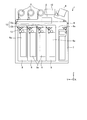
- WO
- WIPO (PCT)
- Prior art keywords
- storage device
- paper sheet
- carry
- sheet storage
- path
- Prior art date
- Legal status (The legal status is an assumption and is not a legal conclusion. Google has not performed a legal analysis and makes no representation as to the accuracy of the status listed.)
- Ceased
Links
Images






Classifications
-
- G—PHYSICS
- G07—CHECKING-DEVICES
- G07D—HANDLING OF COINS OR VALUABLE PAPERS, e.g. TESTING, SORTING BY DENOMINATIONS, COUNTING, DISPENSING, CHANGING OR DEPOSITING
- G07D11/00—Devices accepting coins; Devices accepting, dispensing, sorting or counting valuable papers
- G07D11/009—Depositing devices
-
- G—PHYSICS
- G07—CHECKING-DEVICES
- G07D—HANDLING OF COINS OR VALUABLE PAPERS, e.g. TESTING, SORTING BY DENOMINATIONS, COUNTING, DISPENSING, CHANGING OR DEPOSITING
- G07D11/00—Devices accepting coins; Devices accepting, dispensing, sorting or counting valuable papers
- G07D11/10—Mechanical details
- G07D11/12—Containers for valuable papers
-
- G—PHYSICS
- G07—CHECKING-DEVICES
- G07D—HANDLING OF COINS OR VALUABLE PAPERS, e.g. TESTING, SORTING BY DENOMINATIONS, COUNTING, DISPENSING, CHANGING OR DEPOSITING
- G07D11/00—Devices accepting coins; Devices accepting, dispensing, sorting or counting valuable papers
- G07D11/10—Mechanical details
- G07D11/16—Handling of valuable papers
-
- G—PHYSICS
- G07—CHECKING-DEVICES
- G07D—HANDLING OF COINS OR VALUABLE PAPERS, e.g. TESTING, SORTING BY DENOMINATIONS, COUNTING, DISPENSING, CHANGING OR DEPOSITING
- G07D11/00—Devices accepting coins; Devices accepting, dispensing, sorting or counting valuable papers
- G07D11/10—Mechanical details
- G07D11/16—Handling of valuable papers
- G07D11/18—Diverting into different paths or containers
-
- G—PHYSICS
- G07—CHECKING-DEVICES
- G07D—HANDLING OF COINS OR VALUABLE PAPERS, e.g. TESTING, SORTING BY DENOMINATIONS, COUNTING, DISPENSING, CHANGING OR DEPOSITING
- G07D11/00—Devices accepting coins; Devices accepting, dispensing, sorting or counting valuable papers
- G07D11/20—Controlling or monitoring the operation of devices; Data handling
- G07D11/22—Means for sensing or detection
-
- B—PERFORMING OPERATIONS; TRANSPORTING
- B65—CONVEYING; PACKING; STORING; HANDLING THIN OR FILAMENTARY MATERIAL
- B65H—HANDLING THIN OR FILAMENTARY MATERIAL, e.g. SHEETS, WEBS, CABLES
- B65H2404/00—Parts for transporting or guiding the handled material
- B65H2404/60—Other elements in face contact with handled material
- B65H2404/63—Oscillating, pivoting around an axis parallel to face of material, e.g. diverting means
- B65H2404/632—Wedge member
-
- B—PERFORMING OPERATIONS; TRANSPORTING
- B65—CONVEYING; PACKING; STORING; HANDLING THIN OR FILAMENTARY MATERIAL
- B65H—HANDLING THIN OR FILAMENTARY MATERIAL, e.g. SHEETS, WEBS, CABLES
- B65H29/00—Delivering or advancing articles from machines; Advancing articles to or into piles
- B65H29/58—Article switches or diverters
Definitions
- the present invention relates to a paper sheet storage device and a control method for the paper sheet storage device.
- an automatic teller machine includes a banknote storage device that stores banknotes as paper sheets.
- a banknote storage device that stores banknotes as paper sheets.
- this kind of bill storage device it has a conveyance mechanism which conveys a bill, and a storage part which stores a bill conveyed by a conveyance mechanism, and a plurality of bill storage devices are via a conveyance mechanism. Some are configured to be interconnected.
- This banknote storage device includes a gate member that switches between a storage state in which a banknote transported by the transport mechanism is stored in a storage unit and a passing state in which the banknote sent by the transport mechanism is sent to another banknote storage device.
- the disclosed technology has been made in view of the above, and a paper sheet storage device and a paper sheet that can improve the reliability of the switching operation of the gate member according to the connection state between the paper sheet storage devices. It is an object of the present invention to provide a control method for a storage device.
- One aspect of the paper sheet storage device disclosed in the present application is a storage unit for storing paper sheets, a carry-in path for sending paper sheets to the storage part, a carry-out path for sending paper sheets from the carry-in path, And a gate that is provided in the transport mechanism and is switched between a storage state in which paper sheets are sent from the carry-in path to the storage unit and a passing state in which paper sheets are sent from the carry-in path to the carry-out path.
- a lock mechanism having a member, a lock state that restricts the movement of the gate member, and a release state that releases the lock state; and a lock state in which the lock member restricts the movement of the gate member.
- a release member that releases the paper sheet storage device wherein the release member projects from one side of the carry-in path and the carry-out path to the outside of the paper sheet storage apparatus, and the lock The members are Protruding from the other side of the carry-out path to the outside of the paper sheet storage device, the transport mechanism of the paper sheet storage device, and the paper sheet storage device separate from the paper sheet storage device When the transport mechanism is connected, the lock member is moved by the release member of the other paper sheet storage device.
- the paper sheet storage device disclosed in the present application it is possible to increase the reliability of the switching operation of the gate member according to the connection state of the paper sheet storage devices.
- FIG. 1 is a schematic diagram illustrating the entire banknote handling apparatus according to the first embodiment.
- FIG. 2 is a perspective view illustrating the banknote storage device according to the first embodiment.
- FIG. 3 is a longitudinal sectional view schematically showing the banknote storage device of the first embodiment.
- FIG. 4 is a vertical cross-sectional view schematically showing a connected state of the banknote storage devices of the first embodiment.
- FIG. 5 is a cross-sectional view schematically showing a connected state of the banknote storage devices of the first embodiment.
- FIG. 6A is a perspective view for explaining a locked state in which the lock member restricts the movement of the gate member in the banknote storage device of the first embodiment.
- FIG. 6B is a perspective view for explaining a locked state in which the lock member restricts the movement of the gate member in the banknote storage device of the first embodiment.
- FIG. 7A is a perspective view for explaining a released state in which the lock member releases the locked state of the gate member in the banknote storage device of the first embodiment.
- FIG. 7B is a perspective view for explaining a released state in which the lock member releases the locked state of the gate member in the banknote storage device of the first embodiment.
- FIG. 8 is a longitudinal sectional view schematically showing a state in which the banknote storage devices of Example 2 are connected to each other.
- FIG. 9 is a cross-sectional view schematically showing a state in which the banknote storage devices of Example 2 are connected to each other.
- FIG. 10 is a flowchart for explaining a control method of the banknote storage device of the second embodiment.
- FIG. 11 is a schematic diagram illustrating the entire bill handling apparatus of the third embodiment.
- FIG. 1 is a schematic diagram illustrating the entire banknote handling apparatus according to the first embodiment.
- the banknote handling apparatus 1 includes a deposit / withdrawal unit 4 that deposits / withdraws a banknote 3 as a paper sheet, and a discrimination unit that identifies the banknote 3 deposited in the deposit / withdrawal unit 4. 5 and a temporary storage unit 6 for temporarily storing the banknote 3 conveyed from the discrimination unit 5.
- the banknote handling apparatus 1 is provided with the payment part 7 in which the banknote 3 withdrawn to a user was accommodated, and the collection
- the banknote handling apparatus 1 has the conveyance mechanism 9 which conveys the banknote 3 along the conveyance path 9a between each part 4,5,6,7,8, and each part 4,5,6,7,8,9. And a control unit 10 for controlling each of them.
- the width direction of the banknote handling apparatus 1 is referred to as the X direction
- the front-rear direction of the banknote handling apparatus 1 is referred to as the Y direction
- the up-down direction of the banknote handling apparatus 1 is referred to as the Z direction.
- the X, Y, and Z directions are shown as in FIG. 1.
- the collection unit 8 incorporated in the banknote handling apparatus 1 corresponds to the banknote storage apparatus of the first embodiment.
- the recovery unit 8 will be rephrased as the banknote storage device 8
- the recovery store 8a will be reworded as the storage unit 8a.
- the banknote handling apparatus 1 the number of banknote storage apparatuses 8 to be used is changed as necessary.
- the banknote storage apparatus 8 is additionally provided at the terminal end (the most downstream side) in the transport direction between a plurality of connected banknote storage apparatuses 8. When the bill storage device 8 is further connected, so-called expansion is performed.
- the banknote storage device 8 positioned at the end portion is changed by removing the banknote storage device 8 disposed at the end portion of the group of connected multiple banknote storage devices 8.
- banknote storage device 8 As shown in FIG. 1, inside the banknote storage device 8, two storage units (collection boxes) 8a are arranged side by side in the vertical direction (Z direction).
- the banknote storage device 8 is not limited in the number and arrangement of the storage units 8a, and a configuration having one storage unit 8a may be applied.
- the banknote 3 is used as an example of the paper sheet, but is not limited to the banknote 3. Paper sheets also include securities such as bills, checks, gift certificates, various securities, and stock certificates.
- FIG. 2 is a perspective view illustrating the banknote storage device 8 according to the first embodiment.
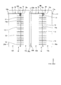
- FIG. 3 is a longitudinal sectional view schematically showing the banknote storage device 8 of the first embodiment.
- FIG. 4 is a longitudinal cross-sectional view schematically showing a connected state of the banknote storage devices 8 according to the first embodiment.
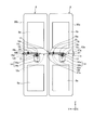
- FIG. 5 is a cross-sectional view schematically illustrating a connected state of the banknote storage devices 8 according to the first embodiment.
- the banknote storage device 8 includes two storage units 8 a that store the banknotes 3, and two storages arranged vertically (Z direction) in FIG. 3.
- the conveyance mechanism 12 which conveys the banknote 3 with respect to the lower accommodating part 8a among the parts 8a is provided.
- the transport mechanism 12 is connected to the transport mechanism 9 of the banknote handling apparatus 1.
- the upper storage unit 8a stores the banknote 3 transported by the transport mechanism 9 of the banknote handling apparatus 1 (FIG. 1).
- the transport mechanism 12 includes a carry-in path 12a for sending the banknote 3 to the lower storage unit 8a, and a carry-out path 12b for sending the banknote 3 from the carry-in path 12a.
- the transport mechanism 12 includes a plurality of transport rollers 12c, a transport belt 12d stretched between the transport rollers 12c, and a drive motor (not shown) that rotationally drives the transport rollers 12c.
- the carry-in path 12a and the carry-out path 12b are shown in a plate shape, but are configured along the conveyance surface of the conveyance belt 12d.
- the banknote storage apparatus 8 is in the accommodation state which sends the banknote 3 from the carrying-in path 12a to the accommodating part 8a, and the passage state which sends the banknote 3 from the carrying-in path 12a to the carrying-out path 12b.
- a switching mechanism 14 having a gate member 13 to be switched is provided.
- the switching mechanism 14 includes a rotary shaft 14a that supports the gate member 13 and a rotary solenoid 14b that rotates the rotary shaft 14a.
- the rotating shaft 14a is provided with an engagement piece 14c that engages with a lock member 18 of the lock mechanism 16 described later.
- the switching mechanism 14 is connected to the control unit 10, and the control unit 10 switches the gate member 13 between a storage state and a passing state.
- the gate member 13 is disposed between the carry-in path 12a and the carry-out path 12b in the transport mechanism 12, and as shown in FIG. 5, the plurality of gate members 13 are spaced along the axial direction of the rotary shaft 14a. Are arranged.
- a conveyance roller 15 that conveys the banknote 3 is rotatably provided at a position adjacent to the gate member 13 (FIG. 1).
- the banknote storage apparatus 8 is provided with the lock mechanism 16 which locks the movement of the gate member 13, and the cancellation
- the lock mechanism 16 includes a lock member 18 that moves between a locked state that restricts movement of the gate member 13 and a released state that releases the locked state.
- the lock mechanism 16 includes a spring member 19 that urges the lock member 18 in the Y direction so that the lock member 18 protrudes outward from the banknote storage device 8.
- the lock member 18 is provided so as to protrude from the side surface 20b on the carry-out path 12b side of the banknote storage device 8 to the outside of the banknote storage apparatus 8, and is supported by the transport mechanism 12 so as to be movable in the Y direction along the carry-out path 12b.
- the lock member 18 has a tip end portion 18 a that protrudes outward from the side surface 20 b of the banknote storage device 8.
- the distal end portion 18a has a pair of inclined surfaces 18b that are inclined with respect to the movement direction (Y direction) of the lock member 18 in the vertical direction (Z direction) perpendicular to the movement direction.
- the pair of inclined surfaces 18b are formed symmetrically with respect to the moving direction of the lock member 18, and the tip end portion 18a is formed in a triangular shape.
- the lock member 18 includes an engagement convex portion 18 c that engages with the engagement piece 14 c of the rotation shaft 14 a of the switching mechanism 14.
- the lock member 18 restricts the gate member 13 from moving from the housed state to the passing state by the engagement convex portion 18c engaging the engagement piece 14c of the rotating shaft 14a by the biasing force of the spring member 19. . That is, the lock member 18 locks the gate member 13 in the storage state in which the banknote 3 is sent into the storage portion 8a.
- the release member 17 is provided so as to protrude outward from the side surface 20a of the banknote storage device 8 on the side of the carry-in path 12a.
- the release member 17 is fixed to the side surface 20 a of the banknote storage device 8.
- the release member 17 releases the locked state in which the lock member 18 restricts the movement of the gate member 13.
- the lock member 18 is moved by the release member 17 of the other banknote storage device 8. Is done.
- the release member 17 protrudes along the movement direction (Y direction) of the lock member 18 and is inclined with respect to the movement direction in the vertical direction (Z direction) perpendicular to the movement direction. It has a surface 17a.
- the pair of inclined surfaces 17a are formed symmetrically with respect to the moving direction of the lock member 18, and the release member 17 is formed in a triangular shape (FIG. 3).
- the banknote storage apparatus 8 to be connected to the banknote storage apparatus 8 connected to the banknote handling apparatus 1 is, for example, upward along the vertical direction (Z direction). Descent from.
- the lock member 18 is gradually pushed in by the inclined surface 17a of the release member 17 descending with respect to the tip end portion 18a of the lock member 18, and the lock member 18 can be smoothly moved along the Y direction.
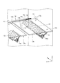
- FIG. 6A is a perspective view for explaining a locked state in which the lock member 18 restricts the movement of the gate member 13 in the banknote storage device 8 according to the first embodiment.
- FIG. 6B is a perspective view for explaining a locked state in which the lock member 18 restricts the movement of the gate member 13 in the banknote storage device 8 according to the first embodiment.
- the additional banknote storage apparatus 8 When connecting the banknote storage apparatuses 8, for example, the additional banknote storage apparatus 8 is lowered from above, for example, with respect to the banknote storage apparatus 8 connected to the transport mechanism 9 of the banknote handling apparatus 1, and the transport mechanism 12. Connect with each other. At this time, as shown in FIGS. 6A and 6B, the tip end portion 18 a of the lock member 18 of the banknote storage device 8 protrudes outward from the side surface 20 b on the carry-out path 12 b side of the banknote storage device 8. The 18 engagement convex portions 18 c are engaged with the engagement pieces 14 c of the rotation shaft 14 a of the switching mechanism 14.
- FIG. 7A is a perspective view for explaining a release state in which the lock member 18 releases the locked state of the gate member 13 in the banknote storage device 8 of the first embodiment.
- FIG. 7B is a perspective view for explaining a released state in which the lock member 18 releases the locked state of the gate member 13 in the banknote storage device 8 according to the first embodiment.
- additional banknote storage is performed so that the carry-out path 12b side of the banknote storage apparatus 8 from which the lock member 18 protrudes outward is connected to the carry-in path 12a side of the additional banknote storage apparatus 8.
- the inclined surface 17 a of the release member 17 comes into contact with the inclined surface 18 b of the distal end portion 18 a of the lock member 18.
- the distal end portion 18 a of the lock member 18 is moved by the release member 17 to the spring member 19. It is pushed into the inside of the banknote storage device 8 against the urging force.
- the lock member 18 protrudes outward from the side surface 20 b on the carry-out path 12 b side, and the gate member 13 is stored by the lock member 18. Locked to state. Therefore, in the conveyance direction of the banknote 3 between the several banknote storage apparatuses 8, the gate member 13 of the banknote storage apparatus 8 located in a termination
- the gate member 13 is locked in the storage state in a state where the additional banknote storage device 8 is not connected to the carry-out path 12b side, and the additional banknote storage apparatus 8 is in the carry-out path.
- the gate member 13 can be switched from the housed state to the passing state while being connected to the 12b side.
- the release member 17 that pushes the front end portion 18a of the lock member 18 is separated from the front end portion 18a. .
- the lock member 18 is moved by the urging force of the spring member 19, the distal end portion 18a protrudes outward from the side surface 20b on the carry-out path 12b side, and the engagement convex portion 18c is the engagement piece of the rotating shaft 14a. 14c is engaged.
- the gate member 13 is restricted to the housed state by the lock member 18.
- the banknote storage apparatus 8 protrudes outward from the banknote storage apparatus 8 from the carry-out path 12b side, and protrudes outward from the banknote storage apparatus 8 from the carry-in path 12a side.
- a release member 17 Provided with a release member 17, and when the transport mechanism 12 of the banknote storage device 8 and the transport mechanism 12 of the banknote storage device 8 different from the banknote storage device 8 are connected, another banknote The lock member 18 is moved by the release member 17 of the storage device 8. Thereby, it is avoided that the gate member 13 moves to the passage state which discharges
- the reliability of the switching operation of the gate member 13 according to the connection state of the banknote storage devices 8 can be enhanced. Moreover, since the movement of the gate member 13 of the banknote storage device 8 at the end portion is restricted in accordance with the increase or decrease in the number of the banknote storage devices 8 connected to each other, the carry-out path 12b side of the banknote storage device 8 at the end portion. It is possible to prevent the banknote 3 from being sent.
- the lock mechanism 16 has the spring member 19 which urges
- the urging force of 19 restricts the gate member 13 from moving from the stored state to the passing state.
- the lock mechanism 16 can regulate the gate member 13 in the housed state with a simple configuration.
- the release member 17 protrudes along the movement direction (Y direction) of the lock member 18 and is inclined with respect to the direction (Z direction) intersecting this movement direction.
- a pair of inclined surfaces 17 a is provided, and the pair of inclined surfaces 17 a is formed symmetrically with respect to the moving direction of the lock member 18.
- the distal end portion 18a of the lock member 18 with which the release member 17 contacts is in a direction (Z direction) that intersects this movement direction with respect to the movement direction (Y direction) of the lock member 18.
- a pair of inclined surfaces 18b are formed symmetrically with respect to the moving direction of the lock member 18.
- the distal end portion 18 a of the lock member 18 protrudes outward from the side surface 20 b on the carry-out path 12 b side of the banknote storage device 8, and the release member 17 is loaded into the banknote storage device 8.
- the lock member 18 and the release member 17 may be disposed opposite to the carry-in path 12a and the carry-out path 12b. .
- the lock member 18 protrudes from the side surface 20a on the carry-in path 12a side of the banknote storage device 8 to the outside of the banknote storage device 8, and the release member 17 stores the banknote from the side surface 20b on the carry-out path 12b side of the banknote storage device 8. It may be projected outward from the device 8, and the same effect as in the first embodiment can be obtained.
- the inclined surface 17a of the release member 17 in the first embodiment is inclined in the vertical direction (Z direction) with respect to the movement direction (Y direction) of the lock member 18, and the bill storage devices 8 are along the vertical direction.
- the inclined surface 17a of the release member 17 is inclined in the horizontal direction (X direction) with respect to the moving direction (Y direction) of the lock member 18, and the bill storage device 8 is slid along the horizontal direction (X direction). And may be configured to be connected to each other.
- the inclined surface 18b of the distal end portion 18a of the lock member 18 is not limited to the configuration inclined in the vertical direction (Z direction) with respect to the moving direction (Y direction) of the lock member 18,
- the locking member 18 may be inclined in the horizontal direction (X direction) with respect to the moving direction (Y direction).
- the lock member 18 in the first embodiment is provided so as to slide in the Y direction.
- the lock member 18 is provided so as to be rotatable around a rotation shaft (not shown).
- the gate member 13 may be configured to move between a locked state in which the gate member 13 is locked and a released state in which the locked state is released.
- FIG. 8 is a longitudinal sectional view schematically showing a state in which the banknote storage devices 8 of the second embodiment are connected to each other.
- FIG. 9 is a cross-sectional view schematically showing a state where the banknote storage devices 8 of the second embodiment are connected to each other.
- the second embodiment is different from the first embodiment in that the movement of the lock member 18 is detected by a position sensor.
- the banknote storage device 8 of the second embodiment includes a position sensor 25 that detects the movement of the lock member 18.
- the position sensor 25 uses an optical sensor, and includes a light emitting unit that emits detection light and a light receiving unit that receives the detection light emitted from the light emitting unit, although not shown.
- the position sensor 25 is disposed in the carry-out path 12 b and is connected to the control unit 10. Based on the detection result of the position sensor 25, the control unit 10 controls the gate member 13 to switch between the housed state and the passing state.
- the lock member 18 is provided with a detection piece 18 d for detecting the movement of the lock member 18 by the position sensor 25.
- 18 d of detection pieces are provided so that it may leave
- the detection piece 18d moves along with the movement of the lock member 18.
- the detection piece 18d moved in this way enters between the light receiving part and the light emitting part of the position sensor 25, and the detection light of the position sensor 25 is blocked by the detection piece 18d, so that the position sensor 25 is connected to the lock member 18. Detect movement.
- the control unit 10 switches the gate member 13 between the housed state and the passing state by the switching mechanism 14 as appropriate. Further, when the detection light of the position sensor 25 is not blocked by the lock member 18, the control unit 10 does not drive the switching mechanism 14 and does not move the gate member 13 in the housed state.
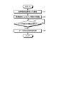
- FIG. 10 is a flowchart for explaining a control method of the banknote storage device 8 according to the second embodiment.
- the transport mechanism 12 and the transport mechanism 12 of the banknote storage device 8 different from the banknote storage device 8 are connected to each other (step S1).
- the position sensor 25 detects whether or not the lock member 18 of the banknote storage device 8 is pushed and moved by the release member 17 of another banknote storage device 8 (step S2). Based on the result, the control unit 10 determines (step S3).
- step S3 when the control unit 10 determines that the lock member 18 has not moved (No), the process returns to step S3 again, and the position sensor 25 continues to detect the movement of the lock member 18.
- the position sensor 25 detects the movement of the lock member 18 when the banknote storage devices 8 are appropriately connected to each other through the respective transport mechanisms 12 so that the lock member 18 is properly moved. Based on the result, the control unit 10 determines that the lock member 18 has moved (YES in step S3). Based on the detection result of the position sensor 25, the control unit 10 controls the gate member 13 to move between the housed state and the passed state (step S4).
- the banknote storage device 8 includes the position sensor 25 that detects the movement of the lock member 18, so that the control unit 10 performs the switching operation of the gate member 13 based on the detection result of the position sensor 25. It becomes possible to control. For this reason, the reliability of the switching operation of the gate member 13 can be further enhanced. Also in the second embodiment, the lock member 18 and the position sensor 25 may be arranged on the carry-in path 12a side of the banknote storage device 8.
- FIG. 11 is a schematic diagram illustrating another example of the entire banknote handling apparatus according to the third embodiment.
- the third embodiment shown in FIG. 11 is different from the first embodiment shown in FIG. 1 in the configuration of the storage portion 8a and the transport mechanism 12.
- the banknote storage device 8 of the third embodiment has one storage unit 8 a, and the transport mechanism 12 that transports the banknote 3 to the storage unit 8 a is a transport mechanism of the banknote handling device 1. 9 is connected.
- the configurations of the gate member 13, the release member 17, the lock member 18 and the like in the third embodiment are the same as those in the first embodiment, and are omitted.
- the banknote storage device 8 is configured such that, for example, the carry-out path 12 b of the banknote storage device 8 disposed at the terminal end in the conveyance direction of the banknote 3 between the plurality of banknote storage devices 8 is a banknote. It is connected to the transport path 9 a of the transport mechanism 9 of the handling device 1.
- the carry-out path 12b of the banknote storage apparatus 8 located in the terminal part may be opened without being connected to the conveyance path 9a.
- the plurality of banknote storage devices 8 are arranged so as to be connected along the horizontal direction (Y direction).
- the present invention is not limited to this configuration.
- the plurality of banknote storage devices 8 may be arranged so as to overlap along the vertical direction (Z direction).
- Banknote handling equipment 3 Banknotes (paper sheets) 8 Banknote storage device, collection unit (paper sheet storage device) 8a Storage part, collection box 10 Control part 12 Transport mechanism 12a Carry-in path 12b Carry-out path 13 Gate member 14 Switching mechanism 14a Rotating shaft 16 Lock mechanism 17 Release member 17a Inclined surface 18 Lock member 18a Tip 18b Inclined surface 18c Engagement convex part 19 Spring member 20a, 20b Side 25 Position sensor
Landscapes
- Physics & Mathematics (AREA)
- General Physics & Mathematics (AREA)
- Engineering & Computer Science (AREA)
- Mechanical Engineering (AREA)
- Pile Receivers (AREA)
- Separation, Sorting, Adjustment, Or Bending Of Sheets To Be Conveyed (AREA)
Abstract
Description
図1は、実施例1の紙幣取扱装置全体を示す模式図である。図1に示すように、実施例1に係る紙幣取扱装置1は、紙葉類としての紙幣3を入出金する入出金部4と、入出金部4に入金された紙幣3を鑑別する鑑別部5と、鑑別部5から搬送された紙幣3を一時的に収納する一時収納部6と、を備える。また、紙幣取扱装置1は、利用者へ出金する紙幣3が収納された出金部7と、一時収納部6から送られた紙幣3を回収庫8aに収納する回収部8と、を備える。また、紙幣取扱装置1は、各部4、5、6、7、8の間で紙幣3を搬送路9aに沿って搬送する搬送機構9と、各部4、5、6、7、8、9をそれぞれ制御する制御部10と、を備える。
図2は、実施例1の紙幣収納装置8を示す透視斜視図である。図3は、実施例1の紙幣収納装置8を模式的に示す縦断面図である。図4は、実施例1の紙幣収納装置8同士の連結状態を模式的に示す縦断面図である。図5は、実施例1の紙幣収納装置8同士の連結状態を模式的に示す横断面図である。
以上のように構成された紙幣収納装置8同士が連結されるときのロック部材18及び解除部材17の動作を説明する。図6Aは、実施例1の紙幣収納装置8において、ロック部材18がゲート部材13の移動を規制したロック状態を説明するための斜視図である。図6Bは、実施例1の紙幣収納装置8において、ロック部材18がゲート部材13の移動を規制したロック状態を説明するための斜視図である。
上述した実施例2の紙幣収納装置8の制御方法について説明する。図10は、実施例2の紙幣収納装置8の制御方法を説明するためのフローチャートである。図10に示すように、紙幣収納装置8は、搬送機構12と、この紙幣収納装置8とは別の紙幣収納装置8の搬送機構12とが相互に連結される(ステップS1)。このとき、紙幣収納装置8のロック部材18が、別の紙幣収納装置8の解除部材17によって押されて移動され(ステップS2)、ロック部材18が移動したか否かを、位置センサ25の検知結果に基づいて制御部10が判断する(ステップS3)。
3 紙幣(紙葉類)
8 紙幣収納装置、回収部(紙葉類収納装置)
8a 収納部、回収庫
10 制御部
12 搬送機構
12a 搬入路
12b 搬出路
13 ゲート部材
14 切り替え機構
14a 回転軸
16 ロック機構
17 解除部材
17a 傾斜面
18 ロック部材
18a 先端部
18b 傾斜面
18c 係合凸部
19 バネ部材
20a、20b 側面
25 位置センサ
Claims (6)
- 紙葉類を収納する収納部と、
前記収納部へ紙葉類を送る搬入路と、前記搬入路から紙葉類を送る搬出路と、を有する搬送機構と、
前記搬送機構に設けられ、前記搬入路から前記収納部へ紙葉類を送る収納状態と、前記搬入路から前記搬出路へ紙葉類を送る通過状態とに切り替えられるゲート部材と、
前記ゲート部材の移動を規制するロック状態と、前記ロック状態を解除する解除状態とに移動するロック部材を有するロック機構と、
前記ロック部材が前記ゲート部材の移動を規制したロック状態を解除する解除部材と、
を備える紙葉類収納装置であって、
前記解除部材は、前記搬入路及び前記搬出路の一方側から前記紙葉類収納装置の外方へ突出して設けられ、
前記ロック部材は、前記搬入路及び前記搬出路の他方側から前記紙葉類収納装置の外方へ突出して設けられ、前記紙葉類収納装置の搬送機構と、当該紙葉類収納装置とは別の紙葉類収納装置の前記搬送機構とが連結されたときに前記別の紙葉類収納装置の前記解除部材によって前記ロック部材が移動される、紙葉類収納装置。 - 前記ロック機構は、前記ロック部材が前記紙葉類収納装置の外方へ突出する方向へ付勢するバネ部材を有し、
前記ロック部材は、前記バネ部材の付勢力によって、前記ゲート部材が前記収納状態から前記通過状態に移動することを規制する、
請求項1に記載の紙葉類収納装置。 - 前記解除部材は、前記ロック部材の移動方向に沿って突出すると共に、前記移動方向に対して当該移動方向に交差する方向に向かって傾斜する一対の傾斜面を有し、当該一対の傾斜面が、前記移動方向に対して対称に形成されている、
請求項1に記載の紙葉類収納装置。 - 前記ロック部材の、前記解除部材が接する先端部は、前記ロック部材の前記移動方向に対して当該移動方向に交差する方向に向かって傾斜する一対の傾斜面を有し、当該一対の傾斜面が、前記移動方向に対して対称に形成されている、
請求項3に記載の紙葉類収納装置。 - 前記ゲート部材の移動を制御する制御部と、
前記ロック部材の移動を検知する位置センサと、を更に備え、
前記制御部は、前記位置センサの検知結果に基づいて前記ゲート部材を前記収納状態と前記通過状態とに制御する、
請求項1に記載の紙葉類収納装置。 - 紙葉類を収納する収納部へ紙葉類を送る搬入路、及び前記搬入路から紙葉類を送る搬出路を有する搬送機構と、前記搬入路から前記収納部へ紙葉類を送る収納状態と、前記搬入路から前記搬出路へ紙葉類を送る通過状態とに切り替えられるゲート部材と、前記ゲート部材の移動を規制するロック部材を有するロック機構と、前記ロック部材が前記ゲート部材の移動を規制したロック状態を解除する解除部材と、前記ゲート部材の移動を制御する制御部と、前記ロック部材の移動を検知する位置センサと、を備える紙葉類収納装置の制御方法であって、
前記位置センサが、前記紙葉類収納装置の前記搬送機構と、当該紙葉類収納装置とは別の紙葉類収納装置の前記搬送機構とが連結されたときに、前記紙葉類収納装置の前記ロック部材が前記別の紙葉類収納装置の前記解除部材によって移動されたことを検知し、
前記制御部が、前記位置センサの検知結果に基づいて前記ゲート部材を前記収納状態と前記通過状態とに制御する、紙葉類収納装置の制御方法。
Priority Applications (5)
| Application Number | Priority Date | Filing Date | Title |
|---|---|---|---|
| CN201880086134.6A CN111587451A (zh) | 2018-01-30 | 2018-01-30 | 纸张存放装置和纸张存放装置的控制方法 |
| JP2019568855A JP6802395B2 (ja) | 2018-01-30 | 2018-01-30 | 紙葉類収納装置及び紙葉類収納装置の制御方法 |
| PCT/JP2018/002910 WO2019150423A1 (ja) | 2018-01-30 | 2018-01-30 | 紙葉類収納装置及び紙葉類収納装置の制御方法 |
| BR112020013400-7A BR112020013400A2 (pt) | 2018-01-30 | 2018-01-30 | dispositivo de armazenamento de folhas de papel e método para controlar dispositivo de armazenamento de folhas de papel |
| US16/933,151 US11810417B2 (en) | 2018-01-30 | 2020-07-20 | Paper sheet storage device and control method of paper sheet storage device |
Applications Claiming Priority (1)
| Application Number | Priority Date | Filing Date | Title |
|---|---|---|---|
| PCT/JP2018/002910 WO2019150423A1 (ja) | 2018-01-30 | 2018-01-30 | 紙葉類収納装置及び紙葉類収納装置の制御方法 |
Related Child Applications (1)
| Application Number | Title | Priority Date | Filing Date |
|---|---|---|---|
| US16/933,151 Continuation US11810417B2 (en) | 2018-01-30 | 2020-07-20 | Paper sheet storage device and control method of paper sheet storage device |
Publications (1)
| Publication Number | Publication Date |
|---|---|
| WO2019150423A1 true WO2019150423A1 (ja) | 2019-08-08 |
Family
ID=67478206
Family Applications (1)
| Application Number | Title | Priority Date | Filing Date |
|---|---|---|---|
| PCT/JP2018/002910 Ceased WO2019150423A1 (ja) | 2018-01-30 | 2018-01-30 | 紙葉類収納装置及び紙葉類収納装置の制御方法 |
Country Status (5)
| Country | Link |
|---|---|
| US (1) | US11810417B2 (ja) |
| JP (1) | JP6802395B2 (ja) |
| CN (1) | CN111587451A (ja) |
| BR (1) | BR112020013400A2 (ja) |
| WO (1) | WO2019150423A1 (ja) |
Citations (3)
| Publication number | Priority date | Publication date | Assignee | Title |
|---|---|---|---|---|
| JPH09235061A (ja) * | 1996-03-01 | 1997-09-09 | Omron Corp | 紙葉類収納装置および取引処理装置 |
| JP2002150356A (ja) * | 2000-11-13 | 2002-05-24 | Japan Cash Machine Co Ltd | 紙幣処理装置 |
| JP2003176073A (ja) * | 2001-12-07 | 2003-06-24 | Omron Corp | 紙葉類処理装置および取引処理装置 |
Family Cites Families (18)
| Publication number | Priority date | Publication date | Assignee | Title |
|---|---|---|---|---|
| DE3245370A1 (de) * | 1982-09-14 | 1984-03-15 | Kienzle Apparate Gmbh, 7730 Villingen-Schwenningen | Einrichtung fuer den transport und die speicherung von banknoten bei selbstkassierenden geraeten |
| EP0514618B2 (de) * | 1991-05-08 | 2000-05-10 | Mars, Incorporated | Zwischenspeicher |
| JP2000103544A (ja) | 1998-09-30 | 2000-04-11 | Hitachi Ltd | 紙葉類搬送装置 |
| JP4048209B2 (ja) | 2000-07-17 | 2008-02-20 | 日本金銭機械株式会社 | 紙幣処理装置 |
| ES2287141T3 (es) | 2000-07-17 | 2007-12-16 | Japan Cash Machine Co., Ltd. | Un aparato de manejo de billetes. |
| JP4832920B2 (ja) * | 2006-02-28 | 2011-12-07 | 富士通株式会社 | シャッタ開閉装置 |
| JP2008021140A (ja) * | 2006-07-13 | 2008-01-31 | Hitachi Omron Terminal Solutions Corp | 紙葉類取扱装置 |
| JP5172257B2 (ja) * | 2007-09-12 | 2013-03-27 | グローリー株式会社 | 紙葉類分岐機構、紙葉類処理装置および紙葉類分岐方法 |
| JP5280976B2 (ja) * | 2009-08-31 | 2013-09-04 | 富士通フロンテック株式会社 | 紙葉取扱装置 |
| JP5647798B2 (ja) * | 2010-02-26 | 2015-01-07 | 日立オムロンターミナルソリューションズ株式会社 | 紙葉取扱装置 |
| JP2013125179A (ja) * | 2011-12-15 | 2013-06-24 | Fuji Xerox Co Ltd | 記録材の搬送方向切り替え装置、画像形成装置およびプログラム |
| JP2014114152A (ja) * | 2012-12-12 | 2014-06-26 | Canon Inc | シート搬送装置及び画像形成装置 |
| JP6088453B2 (ja) * | 2014-02-21 | 2017-03-01 | 富士通フロンテック株式会社 | 紙幣取扱い装置及び紙幣取扱いシステム |
| JP6513366B2 (ja) | 2014-10-16 | 2019-05-15 | 日立オムロンターミナルソリューションズ株式会社 | 搬送方向切替装置、紙葉類取扱装置及び自動取引装置 |
| CN105023346B (zh) * | 2015-08-03 | 2018-01-12 | 昆山古鳌电子机械有限公司 | 纸张类处理装置 |
| JP6747118B2 (ja) * | 2016-07-11 | 2020-08-26 | 富士電機株式会社 | 金銭処理装置 |
| KR101844994B1 (ko) * | 2016-08-17 | 2018-04-03 | 주식회사 에이텍에이피 | 경로 전환 구조와 이를 구비한 매체 보관 장치 및 금융기기 |
| JP7139841B2 (ja) * | 2018-09-28 | 2022-09-21 | 富士フイルムビジネスイノベーション株式会社 | 媒体搬送装置および画像形成装置 |
-
2018
- 2018-01-30 CN CN201880086134.6A patent/CN111587451A/zh active Pending
- 2018-01-30 WO PCT/JP2018/002910 patent/WO2019150423A1/ja not_active Ceased
- 2018-01-30 JP JP2019568855A patent/JP6802395B2/ja active Active
- 2018-01-30 BR BR112020013400-7A patent/BR112020013400A2/pt not_active Application Discontinuation
-
2020
- 2020-07-20 US US16/933,151 patent/US11810417B2/en active Active
Patent Citations (3)
| Publication number | Priority date | Publication date | Assignee | Title |
|---|---|---|---|---|
| JPH09235061A (ja) * | 1996-03-01 | 1997-09-09 | Omron Corp | 紙葉類収納装置および取引処理装置 |
| JP2002150356A (ja) * | 2000-11-13 | 2002-05-24 | Japan Cash Machine Co Ltd | 紙幣処理装置 |
| JP2003176073A (ja) * | 2001-12-07 | 2003-06-24 | Omron Corp | 紙葉類処理装置および取引処理装置 |
Also Published As
| Publication number | Publication date |
|---|---|
| CN111587451A (zh) | 2020-08-25 |
| JP6802395B2 (ja) | 2020-12-16 |
| BR112020013400A2 (pt) | 2020-12-01 |
| US20200349793A1 (en) | 2020-11-05 |
| JPWO2019150423A1 (ja) | 2020-11-19 |
| US11810417B2 (en) | 2023-11-07 |
Similar Documents
| Publication | Publication Date | Title |
|---|---|---|
| KR101023856B1 (ko) | 지엽류 취급 장치 | |
| US10167161B2 (en) | Conveyance path switching module and paper sheet handling apparatus equipped therewith | |
| KR101120907B1 (ko) | 금융 자동화기기 | |
| JP2009143701A (ja) | 紙葉類分離集積装置 | |
| JP5157078B2 (ja) | 紙葉類処理装置 | |
| WO2019150423A1 (ja) | 紙葉類収納装置及び紙葉類収納装置の制御方法 | |
| US11315391B2 (en) | Automatic teller machine having a note storage unit with a door capable of being locked and unlocked | |
| KR20130072494A (ko) | 매체 조출 집적장치 및 그 제어방법 | |
| KR101499736B1 (ko) | 금융자동화기기의 매체 회수 장치 | |
| KR101122478B1 (ko) | 금융자동화기기의 카세트 | |
| JP6259725B2 (ja) | 紙葉類分離集積装置 | |
| JP3575330B2 (ja) | 紙葉類収納装置 | |
| JP7720223B2 (ja) | 紙幣処理装置及び自動取引装置 | |
| US12589968B2 (en) | Guide mechanism and paper sheet handling apparatus | |
| KR101077317B1 (ko) | 금융자동화기기의 리젝트 박스 | |
| JPS6334095B2 (ja) | ||
| EP4152284B1 (en) | Sheet storage apparatus, and sheet handling apparatus | |
| KR101121322B1 (ko) | 금융자동화기기의 매체 회수 장치 | |
| KR101041297B1 (ko) | 지폐입출금부의 스택플레이트 구동장치 | |
| KR20120109986A (ko) | 지엽류 취급 장치 | |
| JPH04174097A (ja) | 紙幣取り込み装置 | |
| WO2019150451A1 (ja) | 紙葉類集積装置及び紙葉類集積装置の制御方法 | |
| KR20220055358A (ko) | 통장발행기의 운용시스템 | |
| JP3558857B2 (ja) | 紙幣処理機 | |
| KR20170096452A (ko) | 매체 정렬 기능을 갖는 다권종 매체 저장장치 |
Legal Events
| Date | Code | Title | Description |
|---|---|---|---|
| 121 | Ep: the epo has been informed by wipo that ep was designated in this application |
Ref document number: 18904001 Country of ref document: EP Kind code of ref document: A1 |
|
| ENP | Entry into the national phase |
Ref document number: 2019568855 Country of ref document: JP Kind code of ref document: A |
|
| NENP | Non-entry into the national phase |
Ref country code: DE |
|
| REG | Reference to national code |
Ref country code: BR Ref legal event code: B01A Ref document number: 112020013400 Country of ref document: BR |
|
| ENP | Entry into the national phase |
Ref document number: 112020013400 Country of ref document: BR Kind code of ref document: A2 Effective date: 20200630 |
|
| 122 | Ep: pct application non-entry in european phase |
Ref document number: 18904001 Country of ref document: EP Kind code of ref document: A1 |