WO2019138768A1 - 空気入りタイヤ - Google Patents
空気入りタイヤ Download PDFInfo
- Publication number
- WO2019138768A1 WO2019138768A1 PCT/JP2018/045702 JP2018045702W WO2019138768A1 WO 2019138768 A1 WO2019138768 A1 WO 2019138768A1 JP 2018045702 W JP2018045702 W JP 2018045702W WO 2019138768 A1 WO2019138768 A1 WO 2019138768A1
- Authority
- WO
- WIPO (PCT)
- Prior art keywords
- sipe
- valley
- peak
- tire
- depth
- Prior art date
Links
Images


Classifications
-
- B—PERFORMING OPERATIONS; TRANSPORTING
- B60—VEHICLES IN GENERAL
- B60C—VEHICLE TYRES; TYRE INFLATION; TYRE CHANGING; CONNECTING VALVES TO INFLATABLE ELASTIC BODIES IN GENERAL; DEVICES OR ARRANGEMENTS RELATED TO TYRES
- B60C11/00—Tyre tread bands; Tread patterns; Anti-skid inserts
- B60C11/03—Tread patterns
- B60C11/12—Tread patterns characterised by the use of narrow slits or incisions, e.g. sipes
- B60C11/1204—Tread patterns characterised by the use of narrow slits or incisions, e.g. sipes with special shape of the sipe
-
- B—PERFORMING OPERATIONS; TRANSPORTING
- B60—VEHICLES IN GENERAL
- B60C—VEHICLE TYRES; TYRE INFLATION; TYRE CHANGING; CONNECTING VALVES TO INFLATABLE ELASTIC BODIES IN GENERAL; DEVICES OR ARRANGEMENTS RELATED TO TYRES
- B60C11/00—Tyre tread bands; Tread patterns; Anti-skid inserts
- B60C11/03—Tread patterns
- B60C11/12—Tread patterns characterised by the use of narrow slits or incisions, e.g. sipes
-
- B—PERFORMING OPERATIONS; TRANSPORTING
- B60—VEHICLES IN GENERAL
- B60C—VEHICLE TYRES; TYRE INFLATION; TYRE CHANGING; CONNECTING VALVES TO INFLATABLE ELASTIC BODIES IN GENERAL; DEVICES OR ARRANGEMENTS RELATED TO TYRES
- B60C11/00—Tyre tread bands; Tread patterns; Anti-skid inserts
- B60C11/03—Tread patterns
- B60C11/0302—Tread patterns directional pattern, i.e. with main rolling direction
-
- B—PERFORMING OPERATIONS; TRANSPORTING
- B60—VEHICLES IN GENERAL
- B60C—VEHICLE TYRES; TYRE INFLATION; TYRE CHANGING; CONNECTING VALVES TO INFLATABLE ELASTIC BODIES IN GENERAL; DEVICES OR ARRANGEMENTS RELATED TO TYRES
- B60C11/00—Tyre tread bands; Tread patterns; Anti-skid inserts
- B60C11/03—Tread patterns
- B60C11/0306—Patterns comprising block rows or discontinuous ribs
-
- B—PERFORMING OPERATIONS; TRANSPORTING
- B60—VEHICLES IN GENERAL
- B60C—VEHICLE TYRES; TYRE INFLATION; TYRE CHANGING; CONNECTING VALVES TO INFLATABLE ELASTIC BODIES IN GENERAL; DEVICES OR ARRANGEMENTS RELATED TO TYRES
- B60C11/00—Tyre tread bands; Tread patterns; Anti-skid inserts
- B60C11/03—Tread patterns
- B60C11/11—Tread patterns in which the raised area of the pattern consists only of isolated elements, e.g. blocks
-
- B—PERFORMING OPERATIONS; TRANSPORTING
- B60—VEHICLES IN GENERAL
- B60C—VEHICLE TYRES; TYRE INFLATION; TYRE CHANGING; CONNECTING VALVES TO INFLATABLE ELASTIC BODIES IN GENERAL; DEVICES OR ARRANGEMENTS RELATED TO TYRES
- B60C11/00—Tyre tread bands; Tread patterns; Anti-skid inserts
- B60C11/03—Tread patterns
- B60C11/12—Tread patterns characterised by the use of narrow slits or incisions, e.g. sipes
- B60C11/1204—Tread patterns characterised by the use of narrow slits or incisions, e.g. sipes with special shape of the sipe
- B60C11/1218—Three-dimensional shape with regard to depth and extending direction
-
- B—PERFORMING OPERATIONS; TRANSPORTING
- B60—VEHICLES IN GENERAL
- B60C—VEHICLE TYRES; TYRE INFLATION; TYRE CHANGING; CONNECTING VALVES TO INFLATABLE ELASTIC BODIES IN GENERAL; DEVICES OR ARRANGEMENTS RELATED TO TYRES
- B60C11/00—Tyre tread bands; Tread patterns; Anti-skid inserts
- B60C11/03—Tread patterns
- B60C11/12—Tread patterns characterised by the use of narrow slits or incisions, e.g. sipes
- B60C11/1204—Tread patterns characterised by the use of narrow slits or incisions, e.g. sipes with special shape of the sipe
- B60C11/1222—Twisted or warped shape in the sipe plane
-
- B—PERFORMING OPERATIONS; TRANSPORTING
- B60—VEHICLES IN GENERAL
- B60C—VEHICLE TYRES; TYRE INFLATION; TYRE CHANGING; CONNECTING VALVES TO INFLATABLE ELASTIC BODIES IN GENERAL; DEVICES OR ARRANGEMENTS RELATED TO TYRES
- B60C11/00—Tyre tread bands; Tread patterns; Anti-skid inserts
- B60C11/03—Tread patterns
- B60C2011/0337—Tread patterns characterised by particular design features of the pattern
- B60C2011/0339—Grooves
- B60C2011/0341—Circumferential grooves
- B60C2011/0344—Circumferential grooves provided at the equatorial plane
-
- B—PERFORMING OPERATIONS; TRANSPORTING
- B60—VEHICLES IN GENERAL
- B60C—VEHICLE TYRES; TYRE INFLATION; TYRE CHANGING; CONNECTING VALVES TO INFLATABLE ELASTIC BODIES IN GENERAL; DEVICES OR ARRANGEMENTS RELATED TO TYRES
- B60C11/00—Tyre tread bands; Tread patterns; Anti-skid inserts
- B60C11/03—Tread patterns
- B60C2011/0337—Tread patterns characterised by particular design features of the pattern
- B60C2011/0339—Grooves
- B60C2011/0374—Slant grooves, i.e. having an angle of about 5 to 35 degrees to the equatorial plane
-
- B—PERFORMING OPERATIONS; TRANSPORTING
- B60—VEHICLES IN GENERAL
- B60C—VEHICLE TYRES; TYRE INFLATION; TYRE CHANGING; CONNECTING VALVES TO INFLATABLE ELASTIC BODIES IN GENERAL; DEVICES OR ARRANGEMENTS RELATED TO TYRES
- B60C11/00—Tyre tread bands; Tread patterns; Anti-skid inserts
- B60C11/03—Tread patterns
- B60C11/12—Tread patterns characterised by the use of narrow slits or incisions, e.g. sipes
- B60C11/1204—Tread patterns characterised by the use of narrow slits or incisions, e.g. sipes with special shape of the sipe
- B60C2011/1209—Tread patterns characterised by the use of narrow slits or incisions, e.g. sipes with special shape of the sipe straight at the tread surface
Definitions
- the present invention relates to a pneumatic tire provided with sipes in a tread portion.
- a block of the tread portion is provided with a plurality of sipes extending in the tire width direction, and braking on wet road surface or ice road surface by edge effect and drainage effect by sipes.
- a sipe is provided, the rigidity of the block is reduced, and when it is new, an increase in wear due to the fall of the block and a reduction in steering stability on a dry road surface occur.
- the sipe is formed into a waveform along the depth direction of the sipe to suppress the falling of the block and to increase the rigidity of the block.
- the tread gauge becomes thin, and the tread rubber is deteriorated to increase the rigidity of the block, so that the braking performance on the wet road surface or the ice road surface is largely reduced. Furthermore, in the case of a corrugated sipe, since removal of the sipe blade provided in the mold at the time of vulcanization molding becomes worse, the block is easily damaged when the sipe blade is removed from the tire. Removal of the sipe blade from such a tire is hereinafter referred to as die removal from the tire.
- Patent Document 1 a pneumatic tire which can effectively improve the deterioration
- the pneumatic tire has sipes in the blocks and / or ribs of the tread portion, and at least at both ends in the longitudinal direction of the sipes, bending portions forming irregularities in the width direction of the sipes are along the sipes depth direction Is provided.
- the size of the unevenness of the bent portion gradually decreases toward the center in the lengthwise direction of the sipe, and the bent portion at one end side in the lengthwise direction of the sipe and the bent portion at the other end in the lengthwise direction are Asperities are formed in opposite directions with respect to the width direction of the sipe.
- the amplitude of the unevenness gradually decreases from one end side to the other side in the length direction of the sipe, and the amplitude of the unevenness in the central portion of the one end side and the other end of the sipe in the length direction is It is zero.
- the unevenness of the wall surface of the other sipe can support the falling down of the wall surface of one sipe, rigidity is secured, while the size of the unevenness of the bent portion of the sipe is the length direction of the sipe Since it becomes gradually smaller toward the center side, it is said that the sipe blade of the mold becomes easy to come off during vulcanization molding.
- mold removal from the pneumatic tire at the end of vulcanization molding is still insufficient.
- the unevenness of the other sipe wall may support the falling of the block or rib, that is, the falling of one sipe wall. It is not done sufficiently and the stiffness does not improve.
- the present invention is a sipe having surface irregularities of a sipe wall surface different from conventional ones, and at the time of manufacturing a tire, the sipe wall surfaces support each other by the irregularities of the sipe wall surfaces while improving die removal from the tire. It is an object of the present invention to provide a pneumatic tire provided with a sipe capable of suppressing a decrease in rigidity due to sipe of a block or a rib.
- the pneumatic tire is The first sipe wall surface of the pair of sipe wall surfaces of the tread portion in contact with the space of the sipe is a surface along the sipe depth direction at each position in the extension direction of the sipe where the sipe extends on the tread surface At least two first peaks and at least one first valley which are corrugated in a corrugated manner to form asperities, and have a corrugated part,
- the second sipe wall surface of the pair of sipe wall surfaces is bent in a wavelike manner to form surface irregularities along the sipe depth direction at each position in the extension direction of the sipe, and the at least two second sipe wall surfaces
- a wave-like portion including at least two second valleys provided to face one peak and at least one second peak provided to face the at least one first valley.
- the first valley portion is interposed between the two first peak portions in the sipe depth direction, and the other end of the sipe in the extension direction from the side of one end of the sipe in the extension direction
- the recess depth of the first valley with respect to the two first peaks gradually extends toward the other end from the one end side while extending toward the end side of the
- the position of at least one of the two first peak portions in the depth direction of the sipe and the position of the first valley portion in the depth direction of the sipe are shallow from the one end side to the other It approaches gradually as it goes to the side of the end.
- the protrusion level of the top of the first peak with respect to the sipe reference plane of the sipe is the same at any position in the extension direction
- the sipe reference plane has, at each position in the extension direction, a variation dimension of unevenness of the first peak portion and the first valley portion along the sipe depth direction with respect to the sipe reference plane as a positive or negative value
- the surface is formed so that the average of the values is zero
- the arrangement of the first peak along the sipe depth direction varies along the extension direction
- the first peak includes a peak ⁇ and a peak ⁇ , and
- the distance between the top of the peak ⁇ and the top of the peak ⁇ in the sipe depth direction is the other end of the sipe in the extension direction from the side of one end of the sipe in the extension direction It is preferable that it gradually narrows toward the side of the
- the first peak portion includes a plurality of ridge lines in which the top portion of the first peak portion extends continuously in the extending direction
- the first valley includes a valley bottom line in which the bottom of the first valley extends continuously in the extending direction, It is preferable that at least one of the ridge line and the valley bottom line is configured to change in position in the sipe depth direction as it proceeds in the extending direction.
- a ridgeline A which is one of the plurality of ridgelines in the first peak portion and a ridgeline B which is the other one approach as they progress to one side in the extending direction.
- the valley bottom line C extends to a first joining position of the ridge line A and the ridge line B, It is preferable that the recess depth of the valley bottom line C becomes gradually shallower as it approaches the first junction position, and the recess depth of the valley bottom line C becomes zero at the first junction position.
- One ridge line D different from the ridge line B among the plurality of ridge lines in the first peak portion is provided parallel to the ridge line A at a deeper position in the sipe depth direction than the ridge line A, It is preferable that the ridgeline D merges with the ridgeline B, and the second merging position of the ridgeline D and the ridgeline B is different from the first merging position.
- the at least one first valley is a plurality of first valleys
- the valley bottom line E of the first valley of one of the plurality of first valleys is provided in parallel to the valley bottom C at a deeper position in the sipe depth direction than the valley bottom C,
- the valley bottom line E preferably merges with the ridge line B and the ridge line D at the second joining position.
- the position in the tire extending direction of the deepest valley portion of the valley bottom line E at which the recess depth is maximum be the same as the position in the tire extending direction of the first joining position.
- the direction in which the recess depth of the valley bottom line C is shallow and the direction in which the recess depth of the valley bottom line E is shallow are opposite to each other.
- the position in the tire extension direction of the deepest valley portion of the valley bottom line C at which the recess depth is maximum be the same as the position in the tire extension direction of the second joining position.
- the valley bottom line C is parallel to the tread surface.
- the rigidity of the block and the rib due to the sipe decreases due to the sipe wall surfaces supporting each other by the unevenness of the sipe wall surfaces while improving the mold removal from the tire at the time of manufacturing the tire. It can be suppressed.
- FIG.3 It is a tire sectional view showing the section of the pneumatic tire of one embodiment. It is a figure which shows the tread pattern of one Embodiment provided in a tread part.
- (A), (b) is a figure explaining Sipe of one embodiment. It is the figure which planarly viewed the sipe wall surface shown in FIG.3 (b).
- (A) to (d) are diagrams schematically showing an example of the shape of the sipe wall surface when cut at the position in the sipe extending direction in FIG.
- FIG. 1 is a tire cross sectional view showing a cross section of a pneumatic tire (hereinafter referred to as a tire) 10 of one embodiment.
- the tire 10 is, for example, a tire for a passenger car.
- the tire for passenger cars is a tire defined in Chapter A of JATMA YEAR BOOK 2010 (Japan Automobile Tire Association Standard).
- the invention can also be applied to the small truck tire defined in Chapter B and the truck and bus tire defined in Chapter C.
- the tire circumferential direction described below refers to the direction in which the tread surface 19 rotates when the tire 10 is rotated about the tire rotation axis, and the tire radial direction extends orthogonal to the tire rotation axis
- the radial direction is referred to as "outside in the tire radial direction", which means the side away from the tire rotation axis in the tire radial direction.
- the tire width direction refers to a direction parallel to the tire rotation axis direction, and the tire width direction outer side refers to both sides of the tire 10 away from the tire equator line CL.
- the pneumatic tire of this embodiment is provided with sipes in the tread portion.
- the first sipe wall surfaces of the pair of sipe wall surfaces of the tread portion in contact with the space (gap) of the sipe form surface irregularities along the sipe depth direction at each position in the sipe extending direction on which the sipe extends on the tread surface To have at least two peaks and at least one valley that bend in an undulating manner.
- the second sipe wall surface of the pair of sipe wall surfaces is bent in a wavelike manner so as to form surface irregularities along the sipe depth direction at each position in the extension direction of the sipe, and at least two first peak portions
- the wave-like portion includes at least two second valleys provided to face each other and at least one second peak provided to face the at least one first valley.
- the wavelike portions of the first sipe wall surface and the second sipe wall surface are preferably provided in a range of 60% to 100% of the entire length of the sipe along the sipe extending direction.
- the recess depth with respect to the first peak portion of the first valley portion in the first sipe wall surface is the sipe extension direction.
- the shapes of the first peak and the first valley are set so as to change according to the position of.
- the first valley portion is sandwiched between the two first peak portions in the sipe depth direction and the side of the other end portion in the extension direction of the sipe from the side of one end portion in the extension direction of the sipe
- the depths of depressions of the first valley with respect to the two first peaks gradually become shallower from the side of the one end to the side of the other end
- the position of at least one sipe depth direction of the two first peak portions and the position of the first valley portion in the sipe depth direction gradually approach from the side of the one end to the side of the other end ing.
- the recess depth of the first valley changes, and peaks and valleys exist at any position in the sipe extending direction. Moreover, the recess depth of the first valley gradually decreases, and the position of the at least one sipe depth direction of the first peak and the position of the first valley in the sipe depth direction gradually approach. ing.
- a second valley and a second peak are provided at positions facing the first peak and the first valley.
- the sipe wall surfaces can support each other due to the unevenness of the sipe wall surfaces, and as a result, it is possible to suppress a decrease in the rigidity of the block or the rib due to the sipe being provided on the block or the rib.
- the recess depth becomes shallow while the first valley portion extends from the deepest valley side toward the end in the extending direction of the sipe, die removal can be improved. That is, it is possible to suppress the decrease in rigidity due to the sipe of the block and the rib of the tread by the sipe wall surfaces supporting each other by the unevenness of the sipe wall surfaces while improving the mold removal from the tire.
- a pneumatic tire provided with such a sipe will be described.
- the tire 10 has a carcass ply layer 12, a belt layer 14, and a bead core 16 as a skeleton or a layer of a skeleton, and around these skeletons, a tread rubber member 18 and a side rubber member 20; It mainly has a bead filler rubber member 22, a rim cushion rubber member 24 and an inner liner rubber member 26.
- the carcass ply layer 12 includes a carcass ply material in which organic fibers are coated with rubber, which is wound around a pair of annular bead cores 16 to form a toroidal shape.
- the carcass ply layer 12 is made of one carcass ply material, but may be made of two carcass ply materials.
- a belt layer 14 composed of two belts 14 a and 14 b is provided on the radially outer side of the carcass ply layer 12 in the tire radial direction.
- the belt layer 14 is a member obtained by coating a rubber on a steel cord arranged at a predetermined angle, for example, 20 to 30 degrees with respect to the tire circumferential direction, and the lower layer belt material 14a is used as the upper layer belt material 14b.
- the width in the tire width direction is wider than that.
- the inclination directions of the steel cords of the two layers of belt members 14a and 14b are opposite to each other. Therefore, the belts 14a and 14b form an alternating layer, and suppress the expansion of the carcass ply layer 12 due to the filled air pressure.
- a tread rubber member 18 is provided on the outer side of the belt layer 14 in the tire radial direction, and side rubber members 20 are connected to both ends of the tread rubber member 18 to form a sidewall portion.
- the tread rubber member 18 is composed of two layers of rubber members, and has an upper tread rubber member 18a provided on the outer side in the tire radial direction and a lower tread rubber member 18b provided on the inner side in the tire radial direction.
- a rim cushion rubber member 24 is provided at an inner end in the tire radial direction of the side rubber member 20 and is in contact with a rim on which the tire 10 is mounted.
- the bead In the tire radial direction outer side of the bead core 16, the bead is sandwiched between a portion of the carcass ply layer 12 before being wound around the bead core 16 and a portion of the carcass ply layer 12 wound around the bead core 16.
- a filler rubber member 22 is provided.
- An inner liner rubber member 26 is provided on the inner surface of the tire 10 facing the air-filled tire cavity area surrounded by the tire 10 and the rim.
- the tire 10 includes a belt cover layer 28 which covers the belt layer 14 from the outer side in the tire radial direction of the belt layer 14 and which is made of an organic fiber coated with rubber.
- the tire 10 has such a tire structure, but the tire structure is not limited to the tire structure shown in FIG. In FIG. 1, illustration of a groove cross section of a tread pattern 50 described later formed on the tread rubber member 18 is omitted.
- FIG. 2 is a view showing a tread pattern 50 of an embodiment provided in the tread portion.
- the tread pattern 50 includes a circumferential main groove 52 extending in the tire circumferential direction on the tire equator line CL, inclined grooves 54 and 56 provided at intervals in the tire circumferential direction, and communication grooves 58, 60, 62 and 64. , Branching grooves 66, 68 are provided.
- the inclined grooves 54 and 56 extend from the circumferential groove 52 toward both sides in the tire width direction to the pattern end which is inclined with respect to the tire circumferential direction and the tire width direction and is on the outer side in the tire width direction.
- the groove width of the inclined grooves 54 and 56 is wider as advancing in the tire width direction.
- the connecting grooves 58 and 60 extend from the inclined grooves 54 and 56 outward in the tire width direction so as to intersect the two adjacent inclined grooves 54 and 56 in the tire circumferential direction, and the second inclined grooves 54 and 56 End.
- the connecting grooves 62, 64 extend from the inclined grooves 54, 56 outward in the tire width direction so as to intersect one inclined groove 54, 56 adjacent in the tire circumferential direction, and the second inclined grooves 54, 56 Terminate without crossing.
- the side which advances in the tire circumferential direction when the contact grooves 58, 60, 62, 64 travel outward in the tire width direction differs from the side which travels in the tire circumferential direction when the inclined grooves 54, 56 travel outward in the tire width direction. It is the other side.
- the branched grooves 66, 68 extend inward in the tire width direction from the position where the inclined grooves 54, 56 connect with the connection grooves 58, 60 and communicate with the circumferential main groove 52.
- a plurality of blocks are formed by such a groove configuration.
- a plurality of sipes 80 are provided in each of the blocks.
- FIGS. 3A and 3B illustrate the sipe 80 according to one embodiment.
- FIG. 3 (a) shows the opening in the tread surface 19 of the sipe 80.
- the openings In the extending sipe extension direction of the sipes 80 on the tread surface, the openings extend in a straight line, but may extend in a gently curved curved shape.
- the width w of the sipe space sandwiched by the sipe wall surfaces 80a and 80b divided along the sipe extension direction of the sipe 80 is, for example, 0.2 to 1.5 mm, and in the tire mold, a plate-like sipe blade is a sipe As a type
- the sipe wall surface 80a (first sipe wall surface) has surface irregularities along the sipe depth direction at each position in the sipe extending direction. It has an undulating portion comprising at least two peaks and at least one valley which bend in an undulating manner to form.
- corrugated shape of sipe wall surface 80a is shown by FIG.3 (b).
- the sipe wall surface 80b is spaced apart along the sipe wall surface 80a at each location to provide a sipe space.
- the portion of the sipe wall surface 80b facing the location of the convex portion of the sipe wall surface 80a is a recess
- the portion of the sipe wall surface 80b facing the location of the recess of the sipe wall surface 80a is a protrusion. Therefore, the sipe wall surface 80b (second sipe wall surface) has at least two second valleys bent in a wavelike manner so as to form surface irregularities along the sipe depth direction at each position in the sipe extension direction It has a wavelike portion provided with one second peak. At least two second valleys are provided to face at least two first peaks, and at least one second peak is provided to face at least one first valley.
- the peak portion is a portion where the tread rubber protrudes from the sipe wall surfaces 80a, 80b
- the valley portion is a portion where the tread rubber is recessed from the sipe wall surfaces 80a, 80b with respect to the peak portion.
- the recess depth with respect to the valleys of the valleys in the sipe wall surface 80a is the maximum recess depth among the recess depths of the valleys. It changes according to the position in the extending direction so as to be smaller than the equivalent or maximum recess depth.
- the depression depth is the depression depth of the valley from the peak located closest to the valley of interest, and when the heights of the peaks are different, the depth of the depression is the larger. In the example shown in FIG. 3 (b), there is a valley 80V1 sandwiched between the peak 80M1 and the peak 80M2 in the sipe depth direction.
- the depression depth of the valley 80V1 with respect to the ridge 80M1 and the ridge 80M2 changes along the sipe extension direction, and in the illustrated example, the depth gradually decreases toward the right in the drawing.
- the valley 80V1 is sandwiched between two peaks 80M1 and 80M2 and extends from the side of one end in the sipe extending direction toward the other end in the sipe extending direction,
- the recess depth of the two ridges 80M1 and 80M2 of the portion 80V1 becomes gradually shallower as it goes from the side of one end of the sipe 80 in the sipe extension direction to the side of the other end, and the ridges 80M1
- the position of at least one sipe in the depth direction of the ridge 80M2 and the position of the valley 80V1 in the depth direction of the sipe proceed from the side of one end of the sipe 80 in the sipe extension direction to the side of the other end It is getting closer gradually.
- the positions in the sipe depth direction of both the mountain portion 80M1 and the mountain portion 80M2 gradually approach the position in the sipe depth direction of the valley portion 80V1. While the distance between the position in the sipe depth direction and the position in the sipe depth direction of the valley 80V1 is constant or broadened, the position in the sipe depth direction of the ridge 80M1 is the position in the sipe depth direction of the valley 80V1 You may approach gradually.
- the position in the sipe depth direction of the ridge 80M1 and the position in the sipe depth direction of the valley 80V1 are constant or broadened, the position in the sipe depth direction of the ridge 80M2 is the sipe of the valley 80V1 The position in the depth direction may be gradually approached.
- the projection height of the sipe wall surface 80b with respect to the valley portion of the sipe wall surface 80b when the peaks and valleys are viewed along the sipe depth direction is extended
- the crests of the sipe wall surface 80b are sandwiched between the valleys from one end of the sipe extending direction of the sipe 80 and the other end of the sipe extending direction is While extending toward the side, the protrusion height of the peak gradually decreases from the side of one end of the sipe 80 in the sipe extending direction to the side of the other end, and
- the position in the sipe depth direction of at least one valley in the valley and the position in the sipe depth direction of the peak progress from one end of the sipe 80 in the sipe extension direction to the other end It is preferable that you are approaching gradually.
- the recess depth of the valley 80V1 gradually becomes shallow, and the position and valley of at least one sipe in the depth direction of the ridge 80M1 and the ridge 80M2 Since the position in the sipe depth direction of the portion 80V1 gradually approaches, it can be engaged with and supported by each other when the sipe wall surfaces fall over. Furthermore, even if one sipe wall surface of the sipe wall surfaces 80a and 80b is deformed in the sipe extending direction, the slopes of the ridges or valleys of the other sipe wall surface are the valleys or ridges of the fallen sipe wall surface. Because the slopes can be supported, the sipe walls can engage and support each other. For this reason, the fall of block rigidity by having provided Sipe 80 in a block of a tread part can be controlled. In addition, since the recess depth of the valley portion 80V1 gradually becomes shallow, the die removal can be improved.
- the protrusion level of the top of the peak with respect to the sipe reference surface in the sipe wall surface 80a is the same.
- the sipe reference plane means, at each position in the sipe extending direction, the variation of the unevenness along the sipe depth direction with respect to the sipe reference plane at the peak and the valley, as a positive or negative value. It is a surface that is formed so that the average of the values is zero. This surface is a flat or curved surface.
- the average of the heights becomes zero.
- the arrangement of the peak 80M1 and the second peak 80M2 along the sipe depth direction changes along the sipe extension direction, and the top of the peak 80M1 (peak ⁇ ) and the second peak 80M2 It is preferable that the spacing in the sipe depth direction at the top of the peak portion ⁇ ) be- comes larger toward the left side of the illustrated example in the extending direction.
- the distance in the sipe depth direction between the top of the peak 80M1 (peak ⁇ ) and the top of the second peak 80M2 (peak ⁇ ) is the distance from the end of one sipe in the sipe extension direction to the other It is preferred that it gradually narrows as it progresses towards the end of the sipe in the direction.
- the valley 80V1 can be provided between the top of the peak 80M1 and the top of the second peak 80M2 in the sipe depth direction, and the recess depth can be changed. When wall surfaces fall over, they can be engaged and supported more effectively.
- the sipe at the top of the peak 80M1 and the top of the second peak 80M2 Since the distance in the depth direction changes in the sipe extending direction, the peak portion of the sipe wall surface 80b opposed to the valley portion 80V1 can be engaged and the sipe wall surface 80a and the sipe wall surface 80b can support each other. For this reason, it is possible to suppress a decrease in block rigidity due to sipes provided in the block.
- the distance between the sipe wall surface 80a (first sipe wall surface) and the sipe wall surface 80b (second sipe wall surface) is constant in the sipe depth direction and the sipe extending direction. It is preferable from the point which wall surfaces 80a and 80b can support uniformly irrespective of a place.
- FIG. 4 is a plan view of the sipe wall surface 80a shown in FIG. 3 (b).
- 5 (a) to 5 (d) are diagrams schematically showing an example of the shape of the sipe wall surface 80a when cut at positions A to D in the sipe extending direction in FIG.
- the crest portion of the sipe wall surface 80a has a convex portion with respect to the peripheral position in the sipe depth direction at the same position in the sipe extension direction and the top portion is continuous along the sipe extension direction And includes ridge lines 80R1, 80R2, 80R3, and 80R4.
- a valley bottom line of the sipe wall surface 80a is a valley bottom line in which a bottom portion having a concave shape with respect to a peripheral position in the sipe depth direction at the same position in the sipe extension direction extends continuously along the sipe extension direction 80B1, 80B2, and 80B3.
- ridge lines 80R1, 80R2, 80R3, and 80R4 are indicated by solid lines, and valley bottom lines 80B1, 80B2, and 80B3 are indicated by alternate long and short dashed lines.
- the ridgeline in this specification is the line of the top when the top of the peak extends linearly, but when the top extends in the form of a flat with a width, the central position in the width direction of the plane is connected It may be a broken line.
- the ridgelines 80R1, 80R2, 80R3, and 80R4 are configured such that the position in the sipe depth direction changes as the ridges 80R1, 80R2, 80R3, and 80R4 move in the sipe extending direction.
- the ridgelines 80R1 and 80R3 change to a deeper position in the sipe depth direction as going to the right in FIG. 4, and the ridgelines 80R2 and 80R4 change to a shallower position in the sipe depth direction to move to the right in FIG. 4 Do.
- a valley bottom line is provided at a position opposite to ridge lines 80R1, 80R2, 80R3, and 80R4 of the sipe wall surface 80a. Since ridgelines are provided at positions opposite to valley bottom lines 80B1, 80B2 and 80B3 of 80a, in the sipe wall surface 80b, the valley bottom line changes its position in the sipe depth direction as it proceeds in the sipe extending direction. It is configured.
- the sipe blade of the tire mold can be obtained.
- the sipe blade is less susceptible to the resistance of the tread rubber, and the sipe blade can be shaped so as to easily come off. For this reason, it is possible to improve die removal from the tire.
- ridgeline 80R1 ridgeline A
- ridgeline 80R2 ridgeline B
- valley bottom line 80B1 valley bottom line C
- the valley bottom line 80B1 extends to the junction position (first junction position) of ridge 80R1 and ridge 80R2.
- the recess depth with respect to ridgeline 80R1 and ridgeline 80R2 in valley bottom line 80B1 gradually becomes shallower as it approaches the merging position (first merging position), and the recess depth of valley bottom line 80B1 is the merging position (first merging position Preferably it is zero at position).
- first merging position Preferably it is zero at position.
- 5 (a) to 5 (d) show the concavo-convex shape at positions A to D shown in FIG. It changes according to the position in the sipe extension direction with respect to the sipe reference plane P.
- the resistance to which the sipe blade is subjected when the sipe blade is extracted from the tread rubber changes in accordance with the magnitude of the variation of the uneven shape in the sipe depth direction, and the smaller the variation, the smaller the resistance.
- the depression depths of valley bottom lines 80B1, 80B2 and 80B3 gradually decrease from the maximum depression depth, so the amount of fluctuation of the asperity shape at positions B and C is smaller than the amount of fluctuation of the surface asperity shape at positions A and D .
- the ridge 80R3 (ridge D) is provided in parallel to the ridge 80R1 at a deeper position in the sipe depth direction than the ridge 80R1 (ridge A), and the ridge 80R3 is a ridge 80R2 (ridge B). Merge with.
- the junction position (second junction position) of ridge line 80R3 and ridge line 80R2 is different from the junction position (first junction position) of ridge line 80R1 and ridge line 80R2.
- the junction position (second junction position) of ridgeline 80R3 and ridgeline 80R2 and the junction position (first junction position) of ridgeline 80R1 and ridgeline 80R2 are the deepest valleys where the recess depth is maximum in the example shown in FIG. , And two positions of opposite ends of the ridge 80R2.
- the valley bottom line 80B2 (valley bottom line E) is provided in parallel with the valley bottom line 80B1 at a deeper position in the sipe depth direction than the valley bottom line 80B1 (valley bottom line C) as shown in FIG.
- the joining position (second joining position) of the valley bottom line 80B2 where the ridge line 80R2 and the ridge line 80R3 join together (the second joining position) is the valley bottom line 80B1 and the ridge line 80R1 and the ridge line This is different from the joining position (first joining position) where 80R2 joins.
- a junction position (second junction position) where valley bottom line 80B2 merges with ridgeline 80R2 and ridgeline 80R3 and a junction position where valley bottom line 80B1 and ridgeline 80R1 and ridgeline 80R2 merge are shown in FIG. In the example shown, it is a position in the sipe extension direction with the deepest valley, and is two positions on the opposite side of the ridgeline 80R2. With such a shape, the valley bottom line can be repeatedly provided in the sipe depth direction, so that the effect of meshing and supporting each other when the sipe wall surfaces fall can be increased.
- the valley bottom line 80B1 (valley bottom line C) is parallel to the tread surface 19 as shown in FIG.
- the plane Q (see FIG. 4) sandwiched between the valley bottom line 80B1 and the ridgeline 80R1 and the plane R (see FIG. 4) sandwiched between the valley bottom line 80B1 and the ridgeline 80R2 are peaks of the sipe wall surface 80b. Opposite the slopes of the section and valley.
- the surfaces R and Q can be supported in the sipe extending direction when the surfaces R and Q fall to the opposing surfaces of the sipe wall surface 80b by deformation. That is, even if the sipe wall surfaces 80a and 80b are deformed so as to fall in the sipe extending direction, they can be engaged and supported each other when the sipe wall surfaces fall.
- the position of the deepest valley portion of the valley bottom line 80B2 (valley bottom line E) at which the depression depth is maximum in the tire extension direction and the ridgeline 80R1 (ridgeline A) is preferable that the position in the tire extension direction of the junction position (1st junction position) of ridgeline 80R2 (ridgeline B) is the same. Thereby, even if ridgeline 80R1 (ridgeline A) and ridgeline 80R2 (ridgeline B) join and valley bottom line 80B1 disappears, deepest valley portion of valley bottom line 80B2 (valley bottom line E) at the same position in the sipe extending direction The meshing of the sipe wall surfaces 80a and 80b is improved.
- the position of the deepest valley portion of the valley bottom line 80B1 (valley bottom line C) in the tire extension direction where the recess depth is maximum, and the joining position (second junction) of ridgeline 80R2 (ridgeline B) and ridgeline 80R3 (ridgeline D) It is preferable that the position in the tire extension direction of the position is the same.
- valley bottom line 80B1 (valley bottom line C) at the same position in the sipe extension direction.
- the meshing of the sipe wall surfaces 80a and 80b is improved because the deepest valley portion of the.
- the direction in which the recess depth of the valley bottom line 80B1 (valley bottom line C) becomes shallow and the direction in which the recess depth of the valley bottom line 80B2 (valley bottom line E) becomes shallow are preferably opposite to each other.
- ridges on the wall of the sipe merge, but the ridges do not necessarily merge and may end in a state in which the ridges approach each other at the end of the sipe 80.
- the maximum recess depth and the inclination angle of the ridge shown in FIG. 4 and the length of the ridge, etc. are the degree of improvement of the target mold removal and the block or rib by providing the sipes. It can set suitably according to the grade of control of a fall of rigidity.
- the maximum recess depth is, for example, 0.1 to 5 mm, preferably 0.3 to 2 mm.
- the length from the position A of the maximum recess depth of the valley bottom line 80B1 shown in FIG. 4 to the position D where the ridges 80R1 and 80R2 merge is 0.5 to 8 mm, preferably 1 to 4 mm.
- Example conventional example
- various sipes were formed on the pneumatic tire shown in FIG. 1 and FIG. 2, and evaluation of die removal and evaluation of tire performance were performed.
- die loss 500 pneumatic tires were prepared, and the reciprocal of the incidence of defects such as cracks around rubber and sipe around sipe due to die loss defect immediately after vulcanization was calculated.
- index 100 the index of the inverse number of the defect occurrence rate of the example was determined.
- the steering performance on a dry road surface affected by the magnitude of the block stiffness which is reduced by providing sipes in the block was investigated.
- the steering performance was evaluated by a driver performing sensory driving and cornering while driving on a preset dry road surface at a predetermined speed.
- a pneumatic tire (tire size: 195 / 65R15 91H) is mounted on a 15 ⁇ 6 J rim (front wheel air pressure: 200 kPa, rear wheel air pressure: 220 kPa) and mounted on a front wheel drive vehicle with a displacement of 1500 cc.
- the evaluation result of Conventional Example 1 was evaluated as an index 100 using an index. The higher the index, the better the maneuverability.
- Table 1 below shows specifications of the conventional example and the example.
- both the maximum protrusion level and the maximum recess level of the peak portion with respect to the tire reference surface were 1 mm.
- the maximum projecting height with respect to the tire reference surface is 0.5 mm.
- the distance from the position A of the maximum recess depth of the valley bottom 80B1 shown in FIG. 4 to the position D where the ridgeline 80R1 and the ridgeline 80R2 merge is set to 8 mm.
- the “* 1” of the “sipe shape” of Conventional Example 1 is a wave shape in which the wave shape along the sipe depth direction is in phase at all positions in the sipe extending direction.
- the amplitude of the wave shape extends from one end in the sipe extending direction while the wave shape along the sipe depth direction maintains the same phase in the sipe extending direction Toward the central part of the direction, the amplitude gradually decreases from the maximum amplitude, the amplitude becomes zero at the central part, and the amplitude increases as it passes through the central part and approaches the other end.
- the wave shape is in the opposite phase to the wave shape between the central portions, and the wave shape has the maximum amplitude at the other end. That is, the sipes of Conventional Example 2 have the form of sipes shown in JP-A-2011-105131.
Landscapes
- Engineering & Computer Science (AREA)
- Mechanical Engineering (AREA)
- Tires In General (AREA)
- Pharmaceuticals Containing Other Organic And Inorganic Compounds (AREA)
- Acyclic And Carbocyclic Compounds In Medicinal Compositions (AREA)
- Transition And Organic Metals Composition Catalysts For Addition Polymerization (AREA)
Abstract
空気入りタイヤのトレッド部にはサイプが設けられている。前記サイプの一対のサイプ壁面の第1のサイプ壁面は、サイプの延在方向の各位置において、サイプ深さ方向に沿って表面凹凸を形成するように波状に屈曲する少なくとも2つの第1山部及び少なくとも1つの第1谷部を備える。前記第1谷部は、前記サイプ深さ方向において前記2つの第1山部の間に挟まれて前記サイプの前記延在方向の一方の端部の側から前記サイプの前記延在方向の他方の端部の側に向かって延びつつ、前記第1谷部の前記2つの第1山部に対する凹み深さは、徐々に浅くなり、かつ、前記2つの第1山部の少なくとも1つの前記サイプ深さ方向の位置と前記第1谷部の前記サイプ深さ方向の位置は、徐々に近づく。
Description
本発明は、トレッド部にサイプが設けられた空気入りタイヤに関する。
一般に、空気入りタイヤ(以降、単にタイヤともいう)においては、トレッド部のブロックにタイヤ幅方向に延びる複数のサイプが設けられ、サイプによるエッジ効果及び排水効果により、ウエット路面や氷上路面での制動性能を向上させるようにしている。しかしながら、サイプを設けるとブロックの剛性が低下するため、新品時においてはブロックの倒れ込みによる摩耗の増大やドライ路面における操縦安定性の低下を生ずる。また、サイプをサイプ深さ方向に沿って波形に形成することによりブロックの倒れ込みを抑制してブロックの剛性を高めるようにした技術が知られている。走行によって摩耗が進行すると、トレッドゲージが薄くなり、トレッドゴムが劣化することによりブロックの剛性が高くなるため、ウエット路面や氷上路面での制動性能が大きく低下する。更に、波形状のサイプでは、加硫成型時の金型に設けられるサイプ刃の抜けが悪くなるため、タイヤからサイプ刃を抜く際にブロックの損傷を生じ易くなる。このようなタイヤからサイプ刃を抜くことを、以降、タイヤからの金型抜けという。
例えば、サイプによる新品時のブロックやリブの剛性の低下を抑制するとともに、摩耗進行に伴ってブロックやリブの剛性が過度に高くなることがなく、加硫成型時におけるタイヤからの金型抜けの悪化を効果的に改善することができる空気入りタイヤが知られている(特許文献1)。
上記空気入りタイヤは、トレッド部のブロック及び/またはリブにサイプを有し、このサイプには少なくともサイプの長さ方向両端部にサイプの幅方向に凹凸をなす屈曲部がサイプ深さ方向に沿って設けられている。このサイプは、屈曲部の凹凸の大きさがサイプの長さ方向中央側に向かって徐々に小さくなり、サイプの長さ方向一端側の屈曲部と長さ方向他端側の屈曲部とが、サイプの幅方向に対して互いに反対方向に凹凸をなしている。
上記サイプは、サイプの長さ方向一端側から他端側に進むに連れて凹凸の振幅が徐々に低くなり、サイプの長さ方向の一端側と他端側の中央部では、凹凸の振幅はゼロになっている。上記空気入りタイヤでは、一方のサイプ壁面の倒れこみを、他方のサイプ壁面の凹凸が支えることができるので、剛性が確保される一方、サイプの屈曲部の凹凸の大きさがサイプの長さ方向中央側に向かって徐々に小さくなることから、加硫成型時、金型のサイプ刃が抜け易くなる、とされている。
しかし、加硫成形終了時における空気入りタイヤからの金型抜けは依然として十分でない。タイヤからの金型抜けを向上させるために、屈曲部の凹凸の振幅を小さくすると、ブロックやリブの倒れこみ、すなわち、一方のサイプ壁面の倒れこみを、他方のサイプ壁面の凹凸が支えることが十分に行われず、剛性が向上しない。
しかし、加硫成形終了時における空気入りタイヤからの金型抜けは依然として十分でない。タイヤからの金型抜けを向上させるために、屈曲部の凹凸の振幅を小さくすると、ブロックやリブの倒れこみ、すなわち、一方のサイプ壁面の倒れこみを、他方のサイプ壁面の凹凸が支えることが十分に行われず、剛性が向上しない。
そこで、本発明は、従来とは異なるサイプ壁面の表面凹凸を有するサイプであって、タイヤ製造時、タイヤからの金型抜けを向上させつつ、サイプ壁面同士の凹凸によってサイプ壁面が互いに支えあうことで、ブロックやリブのサイプによる剛性の低下を抑制することができるサイプを備える空気入りタイヤを提供することを目的とする。
本発明の一態様は、トレッド部にサイプが設けられた空気入りタイヤである。当該空気入りタイヤは、
前記サイプの空間に接する前記トレッド部の一対のサイプ壁面のうち第1のサイプ壁面は、前記サイプがトレッド表面上で延びる前記サイプの延在方向の各位置において、サイプ深さ方向に沿って表面凹凸を形成するように波状に屈曲する少なくとも2つの第1山部及び少なくとも1つの第1谷部を備え波状部分を有し、
前記一対のサイプ壁面のうち第2のサイプ壁面は、前記サイプの延在方向の各位置において、前記サイプ深さ方向に沿って表面凹凸を形成するように波状に屈曲し、前記少なくとも2つの第1山部に対向するように設けられた少なくとも2つの第2谷部及び前記少なくとも1つの第1谷部に対向するように設けられた少なくとも1つの第2山部を備える波状部分を有する。
前記第1谷部は、前記サイプ深さ方向において前記2つの第1山部の間に挟まれて前記サイプの前記延在方向の一方の端部の側から前記サイプの前記延在方向の他方の端部の側に向かって延びつつ、前記第1谷部の前記2つの第1山部に対する凹み深さは、前記一方の端部の側から前記他方の端部の側に進むにつれて徐々に浅くなり、かつ、前記2つの第1山部の少なくとも1つの前記サイプ深さ方向の位置と前記第1谷部の前記サイプ深さ方向の位置は、前記一方の端部の側から前記他方の端部の側に進むにつれて徐々に近づく。
前記延在方向のいずれの位置においても前記第1山部の頂部の、前記サイプのサイプ基準面に対する突出レベルは同じであり、
前記サイプ基準面は、前記延在方向の各位置において、前記第1山部と前記第1谷部の、前記サイプ基準面に対する前記サイプ深さ方向に沿った凹凸の変動寸法を正負の値で表したとき、前記値の平均がゼロになるように形成される面であり、
前記サイプ深さ方向に沿った前記第1山部の配置は、前記延在方向に沿って変化し、
前記第1山部は、山部αと山部βを含み、
前記山部αの頂部と前記山部βの頂部の前記サイプ深さ方向における間隔が、前記サイプの前記延在方向の一方の端部の側から前記サイプの前記延在方向の他方の端部の側に進むに連れて徐々に狭くなる、ことが好ましい。
前記サイプ基準面は、前記延在方向の各位置において、前記第1山部と前記第1谷部の、前記サイプ基準面に対する前記サイプ深さ方向に沿った凹凸の変動寸法を正負の値で表したとき、前記値の平均がゼロになるように形成される面であり、
前記サイプ深さ方向に沿った前記第1山部の配置は、前記延在方向に沿って変化し、
前記第1山部は、山部αと山部βを含み、
前記山部αの頂部と前記山部βの頂部の前記サイプ深さ方向における間隔が、前記サイプの前記延在方向の一方の端部の側から前記サイプの前記延在方向の他方の端部の側に進むに連れて徐々に狭くなる、ことが好ましい。
前記第1山部は、前記第1山部の頂部が前記延在方向に連続して延びる複数の稜線を含み、
前記第1谷部は、前記第1谷部の底部が前記延在方向に連続して延びる谷底線を含み、
前記稜線及び前記谷底線の少なくとも一方は、前記延在方向に進むに連れて、前記サイプ深さ方向の位置が変化するように構成されている、ことが好ましい。
前記第1谷部は、前記第1谷部の底部が前記延在方向に連続して延びる谷底線を含み、
前記稜線及び前記谷底線の少なくとも一方は、前記延在方向に進むに連れて、前記サイプ深さ方向の位置が変化するように構成されている、ことが好ましい。
前記第1山部における前記複数の稜線の1つである稜線Aと他の1つである稜線Bとが前記延在方向の一方の側に進むに連れて近づく、ことが好ましい。
前記稜線Aと前記稜線Bは1つに合流し、
前記サイプ深さ方向における前記稜線Aと前記稜線Bの間に、前記谷底線の1つである谷底線Cが設けられ、
前記谷底線Cは、前記稜線Aと前記稜線Bの第1合流位置まで延びており、
前記谷底線Cの前記凹み深さは、前記第1合流位置に近づくほど徐々に浅くなり、前記谷底線Cの前記凹み深さは、前記第1合流位置においてゼロになる、ことが好ましい。
前記サイプ深さ方向における前記稜線Aと前記稜線Bの間に、前記谷底線の1つである谷底線Cが設けられ、
前記谷底線Cは、前記稜線Aと前記稜線Bの第1合流位置まで延びており、
前記谷底線Cの前記凹み深さは、前記第1合流位置に近づくほど徐々に浅くなり、前記谷底線Cの前記凹み深さは、前記第1合流位置においてゼロになる、ことが好ましい。
前記第1山部における前記複数の稜線のうちの前記稜線Bと異なる1つの稜線Dは、前記稜線Aに比べて前記サイプ深さ方向の深い位置に、前記稜線Aと平行に設けられ、
前記稜線Dは前記稜線Bと合流し、前記稜線Dと前記稜線Bの第2合流位置は、前記第1合流位置と異なる、ことが好ましい。
前記稜線Dは前記稜線Bと合流し、前記稜線Dと前記稜線Bの第2合流位置は、前記第1合流位置と異なる、ことが好ましい。
前記少なくとも1つの第1谷部は、複数の第1谷部であり、
前記複数の第1谷部のうちの1つの第1谷部の谷底線Eは、前記谷底線Cに比べて前記サイプ深さ方向の深い位置に、前記谷底線Cと平行に設けられ、
前記谷底線Eは、前記稜線B及び前記稜線Dと前記第2合流位置で合流する、ことが好ましい。
前記複数の第1谷部のうちの1つの第1谷部の谷底線Eは、前記谷底線Cに比べて前記サイプ深さ方向の深い位置に、前記谷底線Cと平行に設けられ、
前記谷底線Eは、前記稜線B及び前記稜線Dと前記第2合流位置で合流する、ことが好ましい。
前記凹み深さが最大となる前記谷底線Eの最深谷部の前記タイヤ延在方向における位置と、前記第1合流位置のタイヤ延在方向における位置とは、同じである、ことが好ましい。
前記谷底線Cの前記凹み深さが浅くなる方向と、前記谷底線Eの前記凹み深さが浅くなる方向は、互いに逆方向である、ことが好ましい。
前記凹み深さが最大となる前記谷底線Cの最深谷部の前記タイヤ延在方向における位置と、前記第2合流位置のタイヤ延在方向における位置は、同じである、ことが好ましい。
前記谷底線Cは、前記トレッド表面に平行である、ことが好ましい。
上述の空気入りタイヤによれば、タイヤの製造時、タイヤからの金型抜けを向上させつつ、サイプ壁面同士の凹凸によってサイプ壁面が互いに支えあうことで、ブロックやリブのサイプによる剛性の低下を抑制することができる。
以下、一実施形態の空気入りタイヤについて説明する。図1は、一実施形態の空気入りタイヤ(以降、タイヤという)10の断面を示すタイヤ断面図である。
タイヤ10は、例えば、乗用車用タイヤである。乗用車用タイヤは、JATMA YEAR BOOK 2010(日本自動車タイヤ協会規格)のA章に定められるタイヤをいう。この他、B章に定められる小型トラック用タイヤおよびC章に定められるトラック及びバス用タイヤに適用することもできる。
タイヤ10は、例えば、乗用車用タイヤである。乗用車用タイヤは、JATMA YEAR BOOK 2010(日本自動車タイヤ協会規格)のA章に定められるタイヤをいう。この他、B章に定められる小型トラック用タイヤおよびC章に定められるトラック及びバス用タイヤに適用することもできる。
以降で説明するタイヤ周方向とは、タイヤ回転軸を中心にタイヤ10を回転させたとき、トレッド表面19の回転する方向をいい、タイヤ径方向とは、タイヤ回転軸に対して直交して延びる放射方向をいい、タイヤ径方向外側とは、タイヤ回転軸からタイヤ径方向に離れる側をいう。タイヤ幅方向とは、タイヤ回転軸方向に平行な方向をいい、タイヤ幅方向外側とは、タイヤ10のタイヤ赤道線CLから離れる両側をいう。
本実施形態の空気入りタイヤは、トレッド部にサイプが設けられている。このサイプの空間(隙間)に接するトレッド部の一対のサイプ壁面の第1サイプ壁面は、トレッド表面上でサイプが延びるサイプ延在方向の各位置において、サイプ深さ方向に沿って表面凹凸を形成するように波状に屈曲する少なくとも2つの山部及び少なくとも1つの谷部を備える波状部分を有する。一対のサイプ壁面のうち第2のサイプ壁面は、サイプの延在方向の各位置において、サイプ深さ方向に沿って表面凹凸を形成するように波状に屈曲し、少なくとも2つの第1山部に対向するように設けられた少なくとも2つの第2谷部及び少なくとも1つの第1谷部に対向するように設けられた少なくとも1つの第2山部を備える波状部分を有する。第1サイプ壁面及び第2サイプ壁面の波状部分は、サイプ延在方向に沿ったサイプ全体の長さの60%以上100%以下の範囲に設けられることが好ましい。
このとき、サイプ深さ方向に沿って第1山部及び第1谷部を見たときの、第1のサイプ壁面における第1谷部の第1山部に対する凹み深さは、サイプ延在方向の位置に応じて変化するように、第1山部及び第1谷部の形状が設定されている。しかも、第1谷部は、サイプ深さ方向において2つの第1山部の間に挟まれてサイプの延在方向の一方の端部の側からサイプの延在方向の他方の端部の側に向かって延びつつ、第1谷部の2つの第1山部に対する凹み深さは、前記一方の端部の側から前記他方の端部の側に進むにつれて徐々に浅くなり、かつ、前記2つの第1山部の少なくとも1つのサイプ深さ方向の位置と第1谷部のサイプ深さ方向の位置は、前記一方の端部の側から前記他方の端部の側に進むにつれて徐々に近づいている。このように、サイプ壁面の波状部分のサイプ延在方向の各位置で、第1谷部の凹み深さは変化し、サイプ延在方向のどの位置でも山部及び谷部が存在する。しかも、第1谷部の凹み深さは、徐々に浅くなり、かつ、第1山部の少なくとも1つのサイプ深さ方向の位置と第1谷部のサイプ深さ方向の位置は、徐々に近づいている。一方、第2のサイプ壁面において、第1山部及び第1谷部に対向する位置に、第2谷部及び第2山部が設けられている。このため、サイプ壁面同士の凹凸によってサイプ壁面が互いに支えあうことができ、この結果、ブロックやリブにサイプを設けたことによるブロックやリブの剛性の低下を抑制することができる。しかも、第1谷部が最深谷部の側からサイプの延在方向の端部に向かって延びつつ、上記凹み深さは浅くなるので、金型抜けを向上させることができる。すなわち、タイヤからの金型抜けを向上させつつ、サイプ壁面同士の凹凸によってサイプ壁面が互いに支えあうことで、トレッド部のブロックやリブのサイプによる剛性の低下を抑制することができる。
以下、このようなサイプが設けられる空気入りタイヤを説明する。
(タイヤ構造)
タイヤ10は、骨格材あるいは骨格材の層として、カーカスプライ層12と、ベルト層14と、ビードコア16とを有し、これらの骨格材の周りに、トレッドゴム部材18と、サイドゴム部材20と、ビードフィラーゴム部材22と、リムクッションゴム部材24と、インナーライナゴム部材26と、を主に有する。
タイヤ10は、骨格材あるいは骨格材の層として、カーカスプライ層12と、ベルト層14と、ビードコア16とを有し、これらの骨格材の周りに、トレッドゴム部材18と、サイドゴム部材20と、ビードフィラーゴム部材22と、リムクッションゴム部材24と、インナーライナゴム部材26と、を主に有する。
カーカスプライ層12は、一対の円環状のビードコア16の間を巻きまわしてトロイダル形状を成した、有機繊維をゴムで被覆したカーカスプライ材を含む。図1に示すタイヤ10では、カーカスプライ層12は、1つのカーカスプライ材で構成されているが、2つのカーカスプライ材で構成されてもよい。カーカスプライ層12のタイヤ径方向外側に2枚のベルト材14a,14bで構成されるベルト層14が設けられている。ベルト層14は、タイヤ周方向に対して、所定の角度、例えば20~30度傾斜して配されたスチールコードにゴムを被覆した部材であり、下層のベルト材14aが上層のベルト材14bに比べてタイヤ幅方向の幅が広い。2層のベルト材14a,14bのスチールコードの傾斜方向は互いに逆方向である。このため、ベルト材14a,14bは、交錯層となっており、充填された空気圧によるカーカスプライ層12の膨張を抑制する。
ベルト層14のタイヤ径方向外側には、トレッドゴム部材18が設けられ、トレッドゴム部材18の両端部には、サイドゴム部材20が接続されてサイドウォール部を形成している。トレッドゴム部材18は2層のゴム部材で構成され、タイヤ径方向外側に設けられる上層トレッドゴム部材18aとタイヤ径方向内側に設けられる下層トレッドゴム部材18bとを有する。サイドゴム部材20のタイヤ径方向内側の端には、リムクッションゴム部材24が設けられ、タイヤ10を装着するリムと接触する。ビードコア16のタイヤ径方向外側には、ビードコア16の周りに巻きまわす前のカーカスプライ層12の部分と、ビードコア16の周りに巻きまわしたカーカスプライ層12の部分との間に挟まれるようにビードフィラーゴム部材22が設けられている。タイヤ10とリムとで囲まれる空気を充填するタイヤ空洞領域に面するタイヤ10の内表面には、インナーライナゴム部材26が設けられている。
この他に、タイヤ10は、ベルト層14のタイヤ径方向外側からベルト層14を覆う、有機繊維をゴムで被覆したベルトカバー層28を備える。
この他に、タイヤ10は、ベルト層14のタイヤ径方向外側からベルト層14を覆う、有機繊維をゴムで被覆したベルトカバー層28を備える。
タイヤ10は、このようなタイヤ構造を有するが、タイヤ構造は、図1に示すタイヤ構造に限定されない。図1では、トレッドゴム部材18に形成される後述ずるトレッドパターン50の溝断面の図示は省略されている。
(トレッドパターン)
図2は、トレッド部に設けられる一実施形態のトレッドパターン50を示す図である。
トレッドパターン50は、タイヤ赤道線CL上にタイヤ周方向に延びる周方向主溝52と、タイヤ周方向に間隔をあけて設けられる傾斜溝54,56と、連絡溝58,60,62,64と、分岐溝66,68を備える。
傾斜溝54,56は、周方向溝52から、タイヤ幅方向の両側に向かって、タイヤ周方向及びタイヤ幅方向に対して傾斜してタイヤ幅方向外側にあるパターンエンドまで延びる。
傾斜溝54,56の溝幅は、タイヤ幅方向に進むほど広くなっている。
連絡溝58,60は、傾斜溝54,56から、タイヤ周方向に隣り合う2つの傾斜溝54,56と交差するようにタイヤ幅方向外側に延びて、2つ目の傾斜溝54,56で終端する。
連絡溝62,64は、傾斜溝54,56から、タイヤ周方向に隣り合う1つの傾斜溝54,56と交差するようにタイヤ幅方向外側に延びて、2つ目の傾斜溝54,56と交差することなく終端する。連絡溝58,60,62,64がタイヤ幅方向外側に進むときにタイヤ周方向に進む側と、傾斜溝54,56がタイヤ幅方向外側に進むときにタイヤ周方向に進む側とは互いに異なり反対側である。
分岐溝66,68は、傾斜溝54,56が連絡溝58,60と接続する位置からタイヤ幅方向内側に延びて周方向主溝52に連通する。
このような溝構成により、複数のブロックが形成されている。ブロックのそれぞれには、サイプ80が複数設けられている。
タイヤ10のトレッドパターン50は、このような形態であるが、トレッドパターン50は、図2に示すものに限定されない。
(サイプ)
図3(a),(b)は、一実施形態のサイプ80を説明する図である。図3(a)は、サイプ80のトレッド表面19における開口部を示す。トレッド表面においてサイプ80の延びるサイプ延在方向において、開口部は、直線状に延びているが、なだらかに湾曲した湾曲形状に延びてもよい。サイプ80のサイプ延在方向に沿って区画するサイプ壁面80a,80bによって挟まれるサイプ空間の幅wは、例えば0.2~1.5mmであり、タイヤ金型では、板状のサイプ刃がサイプ80を形成する型として、タイヤ金型の溝を形成する凸部が設けられた金型トレッド形成面に装着される。
図3(a),(b)は、一実施形態のサイプ80を説明する図である。図3(a)は、サイプ80のトレッド表面19における開口部を示す。トレッド表面においてサイプ80の延びるサイプ延在方向において、開口部は、直線状に延びているが、なだらかに湾曲した湾曲形状に延びてもよい。サイプ80のサイプ延在方向に沿って区画するサイプ壁面80a,80bによって挟まれるサイプ空間の幅wは、例えば0.2~1.5mmであり、タイヤ金型では、板状のサイプ刃がサイプ80を形成する型として、タイヤ金型の溝を形成する凸部が設けられた金型トレッド形成面に装着される。
サイプ80の空間に接するトレッド部の一対のサイプ壁面80a,80bのうち、サイプ壁面80a(第1のサイプ壁面)は、サイプ延在方向の各位置において、サイプ深さ方向に沿って表面凹凸を形成するように波状に屈曲する少なくとも2つの山部及び少なくとも1つの谷部を備える波状部分を有する。図3(b)には、サイプ壁面80aの凹凸形状が示されている。サイプ壁面80bは、各場所においてサイプ壁面80aに沿うように離間し、サイプ空間を設けている。したがって、サイプ壁面80aの凸部の場所に対向するサイプ壁面80bの部分は凹部であり、サイプ壁面80aの凹部の場所に対向するサイプ壁面80bの部分は凸部である。したがって、サイプ壁面80b(第2のサイプ壁面)は、サイプ延在方向の各位置において、サイプ深さ方向に沿って表面凹凸を形成するように波状に屈曲する少なくとも2つの第2谷部と少なくとも1つの第2山部を備える波状部分を有する。少なくとも2つの第2谷部は、少なくとも2つの第1山部に対向するように設けられ、少なくとも1つの第2山部は、少なくとも1つの第1谷部に対向するように設けられる。ここで、山部とは、サイプ壁面80a,80bからトレッドゴムが突出する部分であり、谷部とは、サイプ壁面80a,80bからトレッドゴムが山部に対して凹む部分である。
さらに詳細には、サイプ深さ方向に沿って山部及び谷部を見たとき、サイプ壁面80aにおける谷部の山部に対する凹み深さは、谷部の上記凹み深さのうち最大凹み深さと同等か最大凹み深さに比べて小さくなるように、延在方向の位置に応じて変化している。凹み深さは、注目する谷部に対して最も近くに位置する山部からの谷部の凹み深さであり、山部の高さが異なる場合、凹み深さが大きい方をいう。図3(b)に示す例では、山部80M1と山部80M2の、サイプ深さ方向の間に挟まれた谷部80V1がある。谷部80V1の山部80M1及び山部80M2に対する凹み深さは、サイプ延在方向に沿って変化し、図示例では、図中右側に行くほど徐々に浅くなっている。
谷部80V1は、2つの山部80M1及び山部80M2の間に挟まれてサイプ延在方向の一方の端部の側からサイプ延在方向の他方の端部の側に向かって延びつつ、谷部80V1の2つの山部80M1及び80M2に対する凹み深さは、サイプ80のサイプ延在方向の一方の端部の側から他方の端部の側に進むにつれて徐々に浅くなり、かつ、山部80M1及び山部80M2の少なくとも1つのサイプ深さ方向の位置と谷部80V1のサイプ深さ方向の位置は、サイプ80のサイプ延在方向の一方の端部の側から他方の端部の側に進むにつれて徐々に近づいている。図3(b)に示す例では、山部80M1及び山部80M2の両方のサイプ深さ方向の位置は谷部80V1のサイプ深さ方向の位置に、徐々に近づいているが、山部80M2のサイプ深さ方向の位置と谷部80V1のサイプ深さ方向の位置との間の間隔が一定あるいは広がる一方、山部80M1のサイプ深さ方向の位置は谷部80V1のサイプ深さ方向の位置に徐々に近づいてもよい。また、山部80M1のサイプ深さ方向の位置と谷部80V1のサイプ深さ方向の位置との間の間隔が一定あるいは広がる一方、山部80M2のサイプ深さ方向の位置は谷部80V1のサイプ深さ方向の位置に徐々に近づいてもよい。
このとき、サイプ壁面80b(第2のサイプ壁面)において、サイプ深さ方向に沿って山部及び谷部を見たときの、サイプ壁面80bにおける山部の谷部に対する突出高さは、延在方向の位置に応じて変化し、サイプ壁面80bの山部は、谷部の間に挟まれてサイプ80のサイプ延在方向の一方の端部の側からサイプ延在方向の他方の端部の側に向かって延びつつ、山部の突出高さは、サイプ80のサイプ延在方向の一方の端部の側から他方の端部の側に進むに連れて徐々に低くなり、かつ、2つの谷部の少なくとも1つの谷部のサイプ深さ方向の位置と山部のサイプ深さ方向の位置は、サイプ80のサイプ延在方向の一方の端部の側から他方の端部の側に進むに連れて徐々に近づいていることが好ましい。
このように、サイプ延在方向の一方に進むに連れて、谷部80V1の凹み深さは徐々に浅くなり、かつ、山部80M1及び山部80M2の少なくとも1つのサイプ深さ方向の位置と谷部80V1のサイプ深さ方向の位置は、徐々に近づくのでサイプ壁面同士が倒れこんだ時互いにかみ合って支え合うことができる。さらに、サイプ壁面80a,80bの一方のサイプ壁面がサイプ延在方向に変形しても、他方のサイプ壁面の山部あるいは谷部の傾斜面が、倒れこんだサイプ壁面の谷部あるいは山部の傾斜面を支えることができるので、サイプ壁面が互いにかみ合って支え合うことができる。このため、トレッド部のブロックにサイプ80を設けたことによるブロック剛性の低下を抑制することができる。しかも、谷部80V1の凹み深さは徐々に浅くなるので、金型抜けを向上させることができる。
一実施形態によれば、サイプ80の延在方向のいずれの位置においても山部の頂部の、サイプ壁面80aにおけるサイプ基準面に対する突出レベルは同じである。ここで、サイプ基準面とは、サイプ延在方向の各位置において、山部と谷部の、サイプ基準面に対するサイプ深さ方向に沿った凹凸の変動寸法を正負の値で表したとき、この値の平均がゼロになるように形成される面である。この面は、平面あるいは湾曲面である。すなわち、サイプ壁面における山部と谷部の、サイプ基準面に対する凹凸を正負の値で表して、凹凸の高さの平均を算出したときに高さの平均がゼロになる。
このとき、サイプ深さ方向に沿った山部80M1、第2山部80M2の配置は、サイプ延在方向に沿って変化し、山部80M1(山部α)の頂部と第2山部80M2(山部β)の頂部のサイプ深さ方向の間隔が、延在方向の図示例の左側に進むに連れて大きくなることが好ましい。いいかえると、山部80M1(山部α)の頂部と第2山部80M2(山部β)の頂部のサイプ深さ方向の間隔が、サイプ延在方向の一方のサイプの端部の側から他方向のサイプの端部の側に進むに連れて徐々に狭くなることが好ましい。このような形状にすることで、山部80M1の頂部と第2山部80M2の頂部の、サイプ深さ方向の間に、谷部80V1を設け、凹み深さを変化させることができるので、サイプ壁面同士が倒れこんだ時互いにかみ合って支え合う効果をより大きくすることができる。特に、サイプ壁面80aとサイプ壁面80bが、サイプ延在方向に変形して、サイプ壁面80aとサイプ壁面80bの一方が他方に倒れ込んでも、山部80M1の頂部と第2山部80M2の頂部のサイプ深さ方向の間隔がサイプ延在方向で変化しているので、サイプ壁面80bの、谷部80V1に対向した山部とが噛み合ってサイプ壁面80aとサイプ壁面80b同士が支え合うことができる。このため、ブロックに設けたサイプによるブロック剛性の低下を抑制することができる。
一実施形態によれば、サイプ壁面80a(第1のサイプ壁面)とサイプ壁面80b(第2のサイプ壁面)の離間距離は、サイプ深さ方向及びサイプ延在方向において一定であることが、サイプ壁面80a,80b同士が場所に拠らず均一に支え合うことができる点から好ましい。
図4は、図3(b)に示すサイプ壁面80aを平面視した図である。図5(a)~(d)は、図4中のサイプ延在方向の位置A~Dで切断したときのサイプ壁面80aの形状の一例を模式的に示す図である。
図4に示すように、サイプ壁面80aの山部は、サイプ延在方向の同じ位置の、サイプ深さ方向の周辺の位置に対して凸形状を成した頂部がサイプ延在方向に沿って連続して延びる稜線80R1,80R2,80R3,80R4を含む。また、サイプ壁面80aの谷部は、サイプ延在方向の同じ位置の、サイプ深さ方向の周辺の位置に対して凹形状を成した底部がサイプ延在方向に沿って連続して延びる谷底線80B1,80B2,80B3を含む。図4では、稜線80R1,80R2,80R3,80R4を実線で示し、谷底線80B1,80B2,80B3を、一点鎖線で示している。なお、本明細書でいう稜線は、山部の頂部が線状に延びる場合は、頂部の線であるが、頂部が幅を持った平面状に延びる場合、平面の幅方向の中心位置を繋げた線であってもよい。
ここで稜線80R1,80R2,80R3,80R4は、サイプ延在方向に進むに連れて、サイプ深さ方向の位置が変化するように構成されている。稜線80R1,80R3は、図4中の右側に進むほど、サイプ深さ方向の深い位置に変化し、稜線80R2,80R4は、図4中の右側に進むほど、サイプ深さ方向の浅い位置に変化する。
なお、図4は、サイプ壁面80aの稜線及び谷底線を示しているが、サイプ壁面80bでは、サイプ壁面80aの稜線80R1,80R2,80R3,80R4に対向する位置に谷底線が設けられ、サイプ壁面80aの谷底線80B1,80B2,80B3に対向する位置に稜線が設けられるので、サイプ壁面80bでは、谷底線は、サイプ延在方向に進むに連れて、サイプ深さ方向の位置が変化するように構成されている。
なお、図4は、サイプ壁面80aの稜線及び谷底線を示しているが、サイプ壁面80bでは、サイプ壁面80aの稜線80R1,80R2,80R3,80R4に対向する位置に谷底線が設けられ、サイプ壁面80aの谷底線80B1,80B2,80B3に対向する位置に稜線が設けられるので、サイプ壁面80bでは、谷底線は、サイプ延在方向に進むに連れて、サイプ深さ方向の位置が変化するように構成されている。
このように、稜線あるいは谷底線のサイプ深さ方向の位置が変わることにより、サイプ延在方向の位置に応じて、山部及び谷部の配置を変化させることにより、タイヤ金型のサイプ刃をトレッドゴムから抜き出すとき、サイプ刃がトレッドゴムの抵抗を受け難く、サイプ刃が抜け易い形状にすることができる。このため、タイヤからの金型抜けを向上させることができる。
上記タイヤからの金型抜けを向上させるために、一実施形態によれば、稜線80R1(稜線A)と稜線80R2(稜線B)とが、あるいは、稜線80R2(稜線A)と稜線80R3(稜線B)とが、あるいは、稜線80R3(稜線A)と稜線80R4(稜線B)とが、サイプ延在方向の一方の側に進むに連れて近づく形態とすることが好ましい。この形態の場合、図4に示すように、近づいた稜線同士が合流してもよいが、合流しなくてもよい。
一実施形態によれば、図4に示すように、例えば、稜線80R1(稜線A)と稜線80R2(稜線B)は1つに合流し、サイプ深さ方向における稜線80R1と稜線80R2の間に、谷底線の1つである谷底線80B1(谷底線C)が設けられ、谷底線80B1は、稜線80R1と稜線80R2の合流位置(第1合流位置)まで延びている。このとき、谷底線80B1における、稜線80R1及び稜線80R2に対する凹み深さは、合流位置(第1合流位置)に近づくほど徐々に浅くなり、谷底線80B1の凹み深さは、合流位置(第1合流位置)においてゼロになることが好ましい。これにより、タイヤからの金型抜けを向上させつつ、サイプ壁面同士が倒れこんだ時互いにかみ合って支え合う効果をより大きくすることができる。
図5(a)~(d)は、図4に示す位置A~Dにおける凹凸形状を示している。サイプ基準面Pに対してサイプ延在方向の位置に応じて変化している。サイプ刃がトレッドゴムから抜き出されるときにサイプ刃が受ける抵抗は、サイプ深さ方向の凹凸形状の変動量の大きさに応じて変化し、変動量が小さいほど小さい。谷底線80B1,80B2,80B3の凹み深さは最大凹み深さから徐々に浅くなるので、位置B,Cにおける凹凸形状の変動量は、位置A,Dにおける表面凹凸形状の変動量に比べて小さい。このため、位置B,Cにおけるサイプ刃が受ける抵抗は小さく、タイヤからの金型抜けを向上させることができる。一方、位置B,Cでは、図5(b),(c)に示すように、サイプ深さ方向に沿った凹凸形状の凹凸回数は、位置A,Dに比べて多い。このため、サイプ壁面同士が倒れこんだ時互いにかみ合って支え合う効果は大きい。
図4に示すように、稜線80R3(稜線D)は、稜線80R1(稜線A)に比べてサイプ深さ方向の深い位置に、稜線80R1と平行に設けられ、稜線80R3は稜線80R2(稜線B)と合流する。稜線80R3と稜線80R2の合流位置(第2合流位置)は、稜線80R1と稜線80R2の合流位置(第1合流位置)と異なっている。稜線80R3と稜線80R2の合流位置(第2合流位置)と、稜線80R1と稜線80R2の合流位置(第1合流位置)とは、図4に示す例では、凹み深さが最大となる最深谷部があるサイプ延在方向の位置であり、稜線80R2の互いに反対側の端の2つの位置である。このような形状により、稜線をサイプ深さ方向に繰り返し設けることができるので、サイプ壁面同士が倒れこんだ時互いにかみ合って支え合う効果を大きくすることができる。
谷底線80B2(谷底線E)は、図4に示すように、谷底線80B1(谷底線C)に比べてサイプ深さ方向の深い位置に、谷底線80B1と平行に設けられ、谷底線80B2は、稜線80R2及び稜線80R3の合流位置(第2合流位置)で合流し、谷底線80B2の、稜線80R2及び稜線80R3と合流する合流位置(第2合流位置)は、谷底線80B1と稜線80R1及び稜線80R2とが合流する合流位置(第1合流位置)と異なっている。谷底線80B2の、稜線80R2及び稜線80R3と合流する合流位置(第2合流位置)と、谷底線80B1と稜線80R1及び稜線80R2とが合流する合流位置(第1合流位置)とは、図4に示す例では、最深谷部があるサイプ延在方向の位置であり、稜線80R2の互いに反対側の2つの位置である。このような形状により、谷底線をサイプ深さ方向に繰り返し設けることができるので、サイプ壁面同士が倒れこんだ時互いにかみ合って支え合う効果を大きくすることができる。
谷底線80B1(谷底線C)は、図4に示すように、トレッド表面19に平行である。この場合、谷底線80B1と稜線80R1の間に挟まれた面Q(図4参照)、及び谷底線80B1と稜線80R2の間に挟まれた面R(図4参照)は、サイプ壁面80bの山部及び谷部の傾斜面と対向する。このとき、面R,Qは、変形によりサイプ壁面80bの対向する面に倒れこんだ時、サイプ延在方向に支えることができる。すなわち、サイプ壁面80a,80bが、サイプ延在方向に倒れこむように変形しても、サイプ壁面同士が倒れこんだ時互いにかみ合って支え合うことができる。
また、一実施形態によれば、図4に示すように、凹み深さが最大となる谷底線80B2(谷底線E)の最深谷部のタイヤ延在方向における位置と、稜線80R1(稜線A)と稜線80R2(稜線B)の合流位置(第1合流位置)のタイヤ延在方向における位置とは、同じであることが好ましい。これにより、稜線80R1(稜線A)と稜線80R2(稜線B)が合流して、谷底線80B1が消滅しても、サイプ延在方向の同じ位置に谷底線80B2(谷底線E)の最深谷部が存在するので、サイプ壁面80a,80bの噛み合わせは向上する。
また、凹み深さが最大となる谷底線80B1(谷底線C)の最深谷部のタイヤ延在方向における位置と、稜線80R2(稜線B)と稜線80R3(稜線D)の合流位置(第2合流位置)のタイヤ延在方向における位置とは、同じであることが好ましい。これにより、稜線80R2(稜線B)と稜線80R3(稜線D)が合流して、谷底線80B2(谷底線E)が消滅しても、サイプ延在方向の同じ位置に谷底線80B1(谷底線C)の最深谷部が存在するので、サイプ壁面80a,80bの噛み合わせは向上する。
また、一実施形態によれば、図4に示すように、谷底線80B1(谷底線C)の凹み深さが浅くなる方向と、谷底線80B2(谷底線E)の凹み深さが浅くなる方向は、互いに逆方向である、ことが好ましい。これにより、サイプ壁面80a,80bの一方が、サイプ延在方向の2つの方向のいずれの方向に変形しても、サイプ壁面80a,80bの噛み合わせが生じるので、サイプ壁面80a,80bを支え合うことができる。
図3(b)に示す形態では、サイプ壁面における稜線同士が合流するが、稜線同士は、必ずしも合流せず、サイプ80の端で稜線同士が互いに近づいた状態で終端してもよい。
なお、最大凹み深さ、及び図4に示す稜線の傾斜角度、及び稜線の長さ、等の寸法は、目標とする金型抜けの向上の程度、及びサイプを設けたことによるブロックあるいはリブの剛性の低下の抑制の程度に応じて適宜設定することができる。最大凹み深さは、例えば、0.1~5mmであり、好ましくは、0.3~2mmである。また、図4に示す谷底線80B1の最大凹み深さの位置Aから稜線80R1,80R2が合流する位置Dまでの長さは、0.5~8mm、好ましくは、1~4mmである。
なお、最大凹み深さ、及び図4に示す稜線の傾斜角度、及び稜線の長さ、等の寸法は、目標とする金型抜けの向上の程度、及びサイプを設けたことによるブロックあるいはリブの剛性の低下の抑制の程度に応じて適宜設定することができる。最大凹み深さは、例えば、0.1~5mmであり、好ましくは、0.3~2mmである。また、図4に示す谷底線80B1の最大凹み深さの位置Aから稜線80R1,80R2が合流する位置Dまでの長さは、0.5~8mm、好ましくは、1~4mmである。
(実施例、従来例)
本実施形態のサイプ80の効果を調べるために、図1、図2に示す空気入りタイヤに種々のサイプを形成して、金型抜けの評価とタイヤ性能の評価を行った。
金型抜けの評価は、空気入りタイヤ500本を作製し、加硫直後の金型抜け不良によるサイプ周りのクラックの発生やゴム欠け等の不良の発生率の逆数を算出し、従来例1の不良の発生率の逆数を基準(指数100)として、実施例の不良の発生率の逆数の指数を求めた。したがって、指数が高い程、不良発生が低いことを表わす。
タイヤ性能の評価では、ブロックにサイプを設けることで低下するブロック剛性の大小の影響を受けるドライ路面における操縦性能を調べた。操縦性能は、予め設定されたドライ路面上を所定の速度で走行しながら、制駆動及びコーナリング旋回を行ってドライバが官能評価した。空気入りタイヤ(タイヤサイズ:195/65R15 91H)は、15×6Jのリムに装着して(前輪空気圧:200kPa、後輪空気圧:220kPa)、排気量1500ccの前輪駆動車に装着して、試験車両とした。従来例1の評価結果を指数100として指数で評価した。指数が高い程、操縦性能が優れていることを表わす。
下記表1には、従来例、実施例の仕様を示す。
なお、従来例1,2及び実施例2では、タイヤ基準面に対する山部の最大の突出レベル及び最大の凹みレベルをいずれも1mmとした。実施例1では、タイヤ基準面に対する最突出高さを0.5mmとした。
実施例1,2では、図4に示す谷底80B1の最大凹み深さの位置Aから稜線80R1及び稜線80R2が合流する位置Dまでの距離を8mmとした。
従来例1の「サイプ形状」の「※1」は、サイプ深さ方向に沿った波形状がサイプ延在方向の全ての位置で同相である波形状である。
従来例2の「サイプ形状」の「※2」は、サイプ深さ方向に沿った波形状がサイプ延在方向において同相を保ちながら、波形状の振幅がサイプ延在方向の一端からサイプ延在方向の中央部に向かって、最大振幅から徐々に小さくなり、中央部で振幅が0になり、さらに、中央部を過ぎて他端に近づくほど振幅が大きくなるが、波形状の位相が一端と中央部の間の波形状の位相と逆相になり、他端で最大振幅になる波形状である。すなわち、従来例2のサイプは、特開2011-105131号公報に示すサイプの形態を有する。
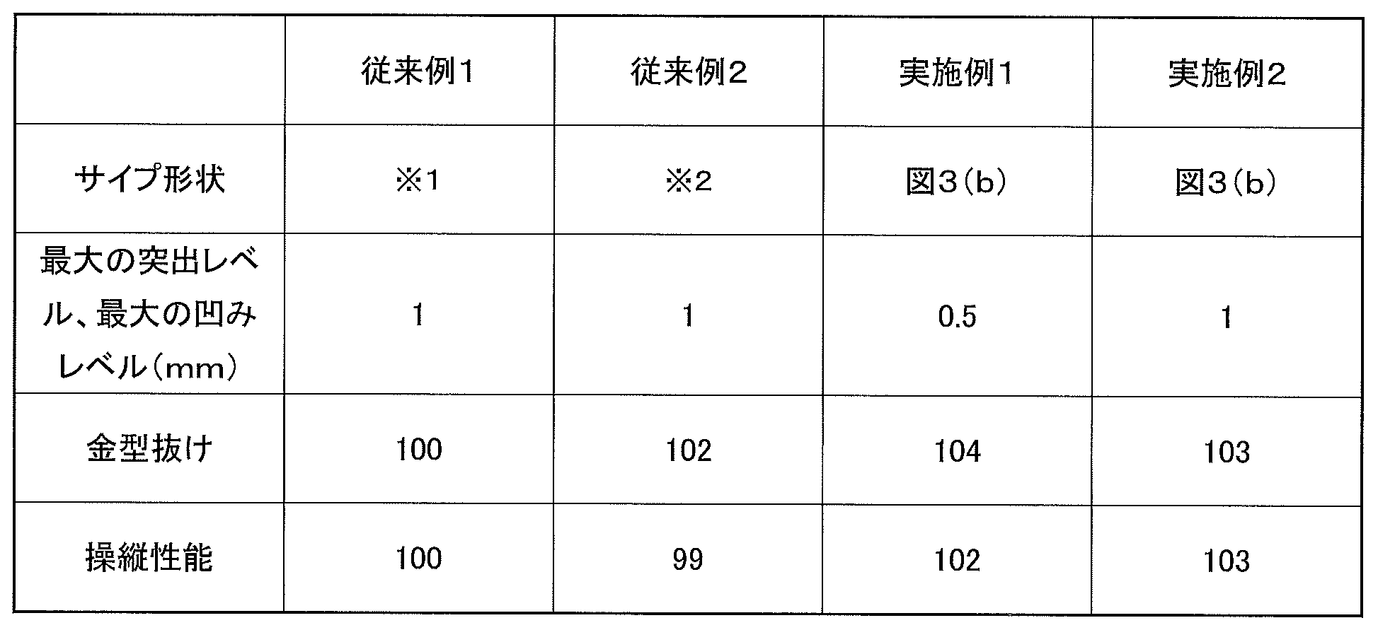
実施例1,2と従来例1,2の比較より、本実施形態のサイプ80は、金型抜けの評価と操縦性能が同時に向上することがわかる。特に実施例1では、波形状の最大の突出レベル及び最大の凹みレベルが従来例1,2に比べて小さくても、金型抜けの評価と操縦性能が同時に向上する。これにより、サイプ80は、タイヤからの金型抜けを向上させつつ、ブロックに設けたサイプによるブロック剛性の低下を抑制することができる、といえる。
以上、本発明の空気入りタイヤについて詳細に説明したが、本発明は実施形態及び実施例に限定されず、本発明の主旨を逸脱しない範囲において、種々の改良や変更をしてもよいのはもちろんである。
10 空気入りタイヤ
12 カーカスプライ層
14 ベルト層
16 ビードコア
18 トレッドゴム部材
19 トレッド表面
20 サイドゴム部材
22 ビードフィラーゴム部材
24 リムクッションゴム部材
26 インナーライナゴム部材
28 ベルトカバー層
50 トレッドパターン
52 周方向主溝
54,56 傾斜溝
58,60,62,64 連絡溝
66,68 分岐溝
80 サイプ
80a,80b サイプ壁面
80M1 山部
80M2 第2山部
80V1 谷部
80R1,80R2,80R3,80R4 稜線
80B1,80B2,80B3 谷底線
12 カーカスプライ層
14 ベルト層
16 ビードコア
18 トレッドゴム部材
19 トレッド表面
20 サイドゴム部材
22 ビードフィラーゴム部材
24 リムクッションゴム部材
26 インナーライナゴム部材
28 ベルトカバー層
50 トレッドパターン
52 周方向主溝
54,56 傾斜溝
58,60,62,64 連絡溝
66,68 分岐溝
80 サイプ
80a,80b サイプ壁面
80M1 山部
80M2 第2山部
80V1 谷部
80R1,80R2,80R3,80R4 稜線
80B1,80B2,80B3 谷底線
Claims (11)
- トレッド部にサイプが設けられた空気入りタイヤであって、
前記サイプの空間に接する前記トレッド部の一対のサイプ壁面のうち第1のサイプ壁面は、前記サイプがトレッド表面上で延びる前記サイプの延在方向の各位置において、サイプ深さ方向に沿って表面凹凸を形成するように波状に屈曲する少なくとも2つの第1山部及び少なくとも1つの第1谷部を備える波状部分を有し、
前記一対のサイプ壁面のうち第2のサイプ壁面は、前記サイプの延在方向の各位置において、前記サイプ深さ方向沿って表面凹凸を形成するように波状に屈曲し、前記少なくとも2つの第1山部に対向するように設けられた少なくとも2つの第2谷部及び前記少なくとも1つの第1谷部に対向するように設けられた少なくとも1つの第2山部を備える波状部分を有し、
前記第1谷部は、前記サイプ深さ方向において前記2つの第1山部の間に挟まれて前記サイプの前記延在方向の一方の端部の側から前記サイプの前記延在方向の他方の端部の側に向かって延びつつ、前記第1谷部の前記2つの第1山部に対する凹み深さは、前記一方の端部の側から前記他方の端部の側に進むにつれて徐々に浅くなり、かつ、前記2つの第1山部の少なくとも1つの前記サイプ深さ方向の位置と前記第1谷部の前記サイプ深さ方向の位置は、前記一方の端部の側から前記他方の端部の側に進むにつれて徐々に近づく、ことを特徴とする空気入りタイヤ。 - 前記延在方向のいずれの位置においても前記第1山部の頂部の、前記サイプのサイプ基準面に対する突出レベルは同じであり、
前記サイプ基準面は、前記延在方向の各位置において、前記第1山部と前記第1谷部の、前記サイプ基準面に対する前記サイプ深さ方向に沿った凹凸の変動寸法を正負の値で表したとき、前記値の平均がゼロになるように形成される面であり、
前記サイプ深さ方向に沿った前記第1山部の配置は、前記延在方向に沿って変化し、
前記第1山部は、山部αと山部βを含み、
前記山部αの頂部と前記山部βの頂部の前記サイプ深さ方向における間隔が、前記サイプの前記延在方向の一方の端部の側から前記サイプの前記延在方向の他方の端部の側に進むに連れて徐々に狭くなる、請求項1に記載の空気入りタイヤ。 - 前記第1山部は、前記第1山部の頂部が前記延在方向に連続して延びる複数の稜線を含み、
前記第1谷部は、前記第1谷部の底部が前記延在方向に連続して延びる谷底線を含み、
前記稜線及び前記谷底線の少なくとも一方は、前記延在方向に進むに連れて、前記サイプ深さ方向の位置が変化するように構成されている、請求項1または2に記載の空気入りタイヤ。 - 前記第1山部における前記複数の稜線の1つである稜線Aと他の1つである稜線Bとが前記延在方向の一方の側に進むに連れて近づく、請求項3に記載の空気入りタイヤ。
- 前記稜線Aと前記稜線Bは1つに合流し、
前記サイプ深さ方向における前記稜線Aと前記稜線Bの間に、前記谷底線の1つである谷底線Cが設けられ、
前記谷底線Cは、前記稜線Aと前記稜線Bの第1合流位置まで延びており、
前記谷底線Cの前記凹み深さは、前記第1合流位置に近づくほど徐々に浅くなり、前記谷底線Cの前記凹み深さは、前記第1合流位置においてゼロになる、請求項4に記載の空気入りタイヤ。 - 前記第1山部における前記複数の稜線のうちの前記稜線Bと異なる1つの稜線Dは、前記稜線Aに比べて前記サイプ深さ方向の深い位置に、前記稜線Aと平行に設けられ、
前記稜線Dは前記稜線Bと合流し、前記稜線Dと前記稜線Bの第2合流位置は、前記第1合流位置と異なる、請求項5に記載の空気入りタイヤ。 - 前記少なくとも1つの第1谷部は、複数の第1谷部であり、
前記複数の第1谷部のうちの1つの第1谷部の谷底線Eは、前記谷底線Cに比べて前記サイプ深さ方向の深い位置に、前記谷底線Cと平行に設けられ、
前記谷底線Eは、前記稜線B及び前記稜線Dと前記第2合流位置で合流する、請求項6に記載の空気入りタイヤ。 - 前記凹み深さが最大となる前記谷底線Eの最深谷部の前記タイヤ延在方向における位置と、前記第1合流位置のタイヤ延在方向における位置とは、同じである、請求項7に記載の空気入りタイヤ。
- 前記谷底線Cの前記凹み深さが浅くなる方向と、前記谷底線Eの前記凹み深さが浅くなる方向は、互いに逆方向である、請求項7または8に記載の空気入りタイヤ。
- 前記凹み深さが最大となる前記谷底線Cの最深谷部の前記タイヤ延在方向における位置と、前記第2合流位置のタイヤ延在方向における位置は、同じである、請求項6~9のいずれか1項に記載の空気入りタイヤ。
- 前記谷底線Cは、前記トレッド表面に平行である、請求項5~10のいずれか1項に記載の空気入りタイヤ。
Priority Applications (5)
| Application Number | Priority Date | Filing Date | Title |
|---|---|---|---|
| RU2020126579A RU2742067C1 (ru) | 2018-01-11 | 2018-12-12 | Пневматическая шина |
| FIEP18899238.2T FI3738793T3 (fi) | 2018-01-11 | 2018-12-12 | Ilmarengas |
| EP18899238.2A EP3738793B1 (en) | 2018-01-11 | 2018-12-12 | Pneumatic tire |
| US16/961,630 US11584165B2 (en) | 2018-01-11 | 2018-12-12 | Pneumatic tire |
| CN201880079462.3A CN111465512B (zh) | 2018-01-11 | 2018-12-12 | 充气轮胎 |
Applications Claiming Priority (2)
| Application Number | Priority Date | Filing Date | Title |
|---|---|---|---|
| JP2018002745A JP7013878B2 (ja) | 2018-01-11 | 2018-01-11 | 空気入りタイヤ |
| JP2018-002745 | 2018-01-11 |
Publications (1)
| Publication Number | Publication Date |
|---|---|
| WO2019138768A1 true WO2019138768A1 (ja) | 2019-07-18 |
Family
ID=67219009
Family Applications (1)
| Application Number | Title | Priority Date | Filing Date |
|---|---|---|---|
| PCT/JP2018/045702 WO2019138768A1 (ja) | 2018-01-11 | 2018-12-12 | 空気入りタイヤ |
Country Status (7)
| Country | Link |
|---|---|
| US (1) | US11584165B2 (ja) |
| EP (1) | EP3738793B1 (ja) |
| JP (1) | JP7013878B2 (ja) |
| CN (1) | CN111465512B (ja) |
| FI (1) | FI3738793T3 (ja) |
| RU (1) | RU2742067C1 (ja) |
| WO (1) | WO2019138768A1 (ja) |
Families Citing this family (2)
| Publication number | Priority date | Publication date | Assignee | Title |
|---|---|---|---|---|
| JP7102904B2 (ja) * | 2018-04-25 | 2022-07-20 | 横浜ゴム株式会社 | 空気入りタイヤ |
| JP6844590B2 (ja) | 2018-07-09 | 2021-03-17 | 横浜ゴム株式会社 | 空気入りタイヤ |
Citations (7)
| Publication number | Priority date | Publication date | Assignee | Title |
|---|---|---|---|---|
| JPH1148721A (ja) * | 1997-08-06 | 1999-02-23 | Ohtsu Tire & Rubber Co Ltd :The | サイプ付き自動車用タイヤ |
| JPH11310012A (ja) * | 1998-03-24 | 1999-11-09 | Continental Ag | 高安定な薄板、そのような薄板を備えた加硫型、切り込みがそのような薄板によってつくられる踏面を有する自動車タイヤ |
| JP2006044570A (ja) * | 2004-08-06 | 2006-02-16 | Bridgestone Corp | 空気入りタイヤとその製造方法 |
| JP2007186053A (ja) * | 2006-01-12 | 2007-07-26 | Bridgestone Corp | 空気入りタイヤ |
| JP2011105131A (ja) | 2009-11-17 | 2011-06-02 | Yokohama Rubber Co Ltd:The | 空気入りタイヤ |
| JP2011105135A (ja) * | 2009-11-17 | 2011-06-02 | Yokohama Rubber Co Ltd:The | 空気入りタイヤ |
| JP2013103579A (ja) * | 2011-11-11 | 2013-05-30 | Bridgestone Corp | 空気入りタイヤ |
Family Cites Families (13)
| Publication number | Priority date | Publication date | Assignee | Title |
|---|---|---|---|---|
| DE3324649A1 (de) * | 1983-07-08 | 1985-01-31 | Continental Gummi-Werke Ag, 3000 Hannover | Fahrzeugluftreifen |
| JP3954174B2 (ja) * | 1997-10-23 | 2007-08-08 | 株式会社ブリヂストン | 空気入りタイヤ |
| JP2000177329A (ja) | 1998-12-14 | 2000-06-27 | Ohtsu Tire & Rubber Co Ltd :The | タイヤトレッド |
| JP3894743B2 (ja) * | 2001-04-05 | 2007-03-22 | 横浜ゴム株式会社 | 空気入りタイヤ |
| JP2006341816A (ja) * | 2005-06-10 | 2006-12-21 | Bridgestone Corp | 空気入りタイヤ |
| US20090000713A1 (en) * | 2007-06-27 | 2009-01-01 | Bridgestone Firestone North American Tire, Llc | Tire including segmented sipes |
| JP5012357B2 (ja) * | 2007-09-20 | 2012-08-29 | 横浜ゴム株式会社 | 空気入りタイヤ |
| BRPI0722319B1 (pt) | 2007-12-19 | 2019-09-24 | Pirelli Tyre S.P.A. | Pneu para rodas de veículo |
| DE102010061373A1 (de) | 2010-12-20 | 2012-06-21 | Continental Reifen Deutschland Gmbh | Fahrzeugluftreifen |
| RU2577422C2 (ru) | 2011-11-04 | 2016-03-20 | Бриджстоун Корпорейшн | Пневматическая шина |
| WO2013114852A1 (ja) * | 2012-02-01 | 2013-08-08 | 株式会社ブリヂストン | 空気入りタイヤ |
| JP5835112B2 (ja) * | 2012-06-05 | 2015-12-24 | 横浜ゴム株式会社 | 空気入りタイヤ |
| ITTO20120871A1 (it) * | 2012-10-05 | 2014-04-06 | Bridgestone Corp | Striscia di battistrada per un pneumatico invernale provvista di intagli tridimensionali |
-
2018
- 2018-01-11 JP JP2018002745A patent/JP7013878B2/ja active Active
- 2018-12-12 EP EP18899238.2A patent/EP3738793B1/en active Active
- 2018-12-12 CN CN201880079462.3A patent/CN111465512B/zh active Active
- 2018-12-12 US US16/961,630 patent/US11584165B2/en active Active
- 2018-12-12 WO PCT/JP2018/045702 patent/WO2019138768A1/ja unknown
- 2018-12-12 FI FIEP18899238.2T patent/FI3738793T3/fi active
- 2018-12-12 RU RU2020126579A patent/RU2742067C1/ru active
Patent Citations (7)
| Publication number | Priority date | Publication date | Assignee | Title |
|---|---|---|---|---|
| JPH1148721A (ja) * | 1997-08-06 | 1999-02-23 | Ohtsu Tire & Rubber Co Ltd :The | サイプ付き自動車用タイヤ |
| JPH11310012A (ja) * | 1998-03-24 | 1999-11-09 | Continental Ag | 高安定な薄板、そのような薄板を備えた加硫型、切り込みがそのような薄板によってつくられる踏面を有する自動車タイヤ |
| JP2006044570A (ja) * | 2004-08-06 | 2006-02-16 | Bridgestone Corp | 空気入りタイヤとその製造方法 |
| JP2007186053A (ja) * | 2006-01-12 | 2007-07-26 | Bridgestone Corp | 空気入りタイヤ |
| JP2011105131A (ja) | 2009-11-17 | 2011-06-02 | Yokohama Rubber Co Ltd:The | 空気入りタイヤ |
| JP2011105135A (ja) * | 2009-11-17 | 2011-06-02 | Yokohama Rubber Co Ltd:The | 空気入りタイヤ |
| JP2013103579A (ja) * | 2011-11-11 | 2013-05-30 | Bridgestone Corp | 空気入りタイヤ |
Non-Patent Citations (1)
| Title |
|---|
| See also references of EP3738793A4 |
Also Published As
| Publication number | Publication date |
|---|---|
| EP3738793A4 (en) | 2021-08-25 |
| CN111465512A (zh) | 2020-07-28 |
| US20200338931A1 (en) | 2020-10-29 |
| US11584165B2 (en) | 2023-02-21 |
| EP3738793A1 (en) | 2020-11-18 |
| RU2742067C1 (ru) | 2021-02-02 |
| FI3738793T3 (fi) | 2023-05-08 |
| JP7013878B2 (ja) | 2022-02-01 |
| EP3738793B1 (en) | 2023-02-15 |
| JP2019119427A (ja) | 2019-07-22 |
| CN111465512B (zh) | 2022-12-06 |
Similar Documents
| Publication | Publication Date | Title |
|---|---|---|
| JP6672900B2 (ja) | 空気入りタイヤ | |
| JP6106183B2 (ja) | 空気入りタイヤ | |
| CN103826873B (zh) | 充气轮胎 | |
| JP5387659B2 (ja) | 空気入りタイヤ | |
| JP5102711B2 (ja) | 空気入りタイヤ | |
| CN105644275A (zh) | 充气轮胎 | |
| US11203234B2 (en) | Pneumatic tire | |
| JP6287554B2 (ja) | 空気入りタイヤ | |
| JP6891709B2 (ja) | 空気入りタイヤ | |
| WO2019131837A1 (ja) | 空気入りタイヤ | |
| JP6714985B2 (ja) | タイヤ | |
| WO2019138768A1 (ja) | 空気入りタイヤ | |
| JP6449005B2 (ja) | 空気入りタイヤ | |
| JP6926467B2 (ja) | 空気入りタイヤ | |
| JP5909136B2 (ja) | 空気入りタイヤ | |
| JP5041466B2 (ja) | 空気入りタイヤ | |
| JP6107242B2 (ja) | 空気入りタイヤ | |
| JP7102904B2 (ja) | 空気入りタイヤ | |
| JP2016112926A (ja) | 空気入りタイヤ | |
| WO2021002209A1 (ja) | 空気入りタイヤ | |
| JP7119529B2 (ja) | 空気入りタイヤ | |
| JP6844590B2 (ja) | 空気入りタイヤ | |
| JP6077288B2 (ja) | 空気入りタイヤ | |
| JP7415142B2 (ja) | 空気入りタイヤ | |
| JP4992328B2 (ja) | タイヤ |
Legal Events
| Date | Code | Title | Description |
|---|---|---|---|
| 121 | Ep: the epo has been informed by wipo that ep was designated in this application |
Ref document number: 18899238 Country of ref document: EP Kind code of ref document: A1 |
|
| NENP | Non-entry into the national phase |
Ref country code: DE |
|
| ENP | Entry into the national phase |
Ref document number: 2018899238 Country of ref document: EP Effective date: 20200811 |