WO2019130845A1 - Récipient en résine synthétique - Google Patents
Récipient en résine synthétique Download PDFInfo
- Publication number
- WO2019130845A1 WO2019130845A1 PCT/JP2018/041394 JP2018041394W WO2019130845A1 WO 2019130845 A1 WO2019130845 A1 WO 2019130845A1 JP 2018041394 W JP2018041394 W JP 2018041394W WO 2019130845 A1 WO2019130845 A1 WO 2019130845A1
- Authority
- WO
- WIPO (PCT)
- Prior art keywords
- shoulder
- synthetic resin
- mouth
- layer body
- resin container
- Prior art date
Links
Images


Classifications
-
- B—PERFORMING OPERATIONS; TRANSPORTING
- B65—CONVEYING; PACKING; STORING; HANDLING THIN OR FILAMENTARY MATERIAL
- B65D—CONTAINERS FOR STORAGE OR TRANSPORT OF ARTICLES OR MATERIALS, e.g. BAGS, BARRELS, BOTTLES, BOXES, CANS, CARTONS, CRATES, DRUMS, JARS, TANKS, HOPPERS, FORWARDING CONTAINERS; ACCESSORIES, CLOSURES, OR FITTINGS THEREFOR; PACKAGING ELEMENTS; PACKAGES
- B65D1/00—Containers having bodies formed in one piece, e.g. by casting metallic material, by moulding plastics, by blowing vitreous material, by throwing ceramic material, by moulding pulped fibrous material, by deep-drawing operations performed on sheet material
- B65D1/02—Bottles or similar containers with necks or like restricted apertures, designed for pouring contents
- B65D1/0207—Bottles or similar containers with necks or like restricted apertures, designed for pouring contents characterised by material, e.g. composition, physical features
- B65D1/0215—Bottles or similar containers with necks or like restricted apertures, designed for pouring contents characterised by material, e.g. composition, physical features multilayered
-
- B—PERFORMING OPERATIONS; TRANSPORTING
- B65—CONVEYING; PACKING; STORING; HANDLING THIN OR FILAMENTARY MATERIAL
- B65D—CONTAINERS FOR STORAGE OR TRANSPORT OF ARTICLES OR MATERIALS, e.g. BAGS, BARRELS, BOTTLES, BOXES, CANS, CARTONS, CRATES, DRUMS, JARS, TANKS, HOPPERS, FORWARDING CONTAINERS; ACCESSORIES, CLOSURES, OR FITTINGS THEREFOR; PACKAGING ELEMENTS; PACKAGES
- B65D1/00—Containers having bodies formed in one piece, e.g. by casting metallic material, by moulding plastics, by blowing vitreous material, by throwing ceramic material, by moulding pulped fibrous material, by deep-drawing operations performed on sheet material
- B65D1/02—Bottles or similar containers with necks or like restricted apertures, designed for pouring contents
- B65D1/0223—Bottles or similar containers with necks or like restricted apertures, designed for pouring contents characterised by shape
- B65D1/023—Neck construction
- B65D1/0246—Closure retaining means, e.g. beads, screw-threads
-
- B—PERFORMING OPERATIONS; TRANSPORTING
- B65—CONVEYING; PACKING; STORING; HANDLING THIN OR FILAMENTARY MATERIAL
- B65D—CONTAINERS FOR STORAGE OR TRANSPORT OF ARTICLES OR MATERIALS, e.g. BAGS, BARRELS, BOTTLES, BOXES, CANS, CARTONS, CRATES, DRUMS, JARS, TANKS, HOPPERS, FORWARDING CONTAINERS; ACCESSORIES, CLOSURES, OR FITTINGS THEREFOR; PACKAGING ELEMENTS; PACKAGES
- B65D1/00—Containers having bodies formed in one piece, e.g. by casting metallic material, by moulding plastics, by blowing vitreous material, by throwing ceramic material, by moulding pulped fibrous material, by deep-drawing operations performed on sheet material
- B65D1/40—Details of walls
-
- B—PERFORMING OPERATIONS; TRANSPORTING
- B65—CONVEYING; PACKING; STORING; HANDLING THIN OR FILAMENTARY MATERIAL
- B65D—CONTAINERS FOR STORAGE OR TRANSPORT OF ARTICLES OR MATERIALS, e.g. BAGS, BARRELS, BOTTLES, BOXES, CANS, CARTONS, CRATES, DRUMS, JARS, TANKS, HOPPERS, FORWARDING CONTAINERS; ACCESSORIES, CLOSURES, OR FITTINGS THEREFOR; PACKAGING ELEMENTS; PACKAGES
- B65D23/00—Details of bottles or jars not otherwise provided for
- B65D23/02—Linings or internal coatings
-
- B—PERFORMING OPERATIONS; TRANSPORTING
- B65—CONVEYING; PACKING; STORING; HANDLING THIN OR FILAMENTARY MATERIAL
- B65D—CONTAINERS FOR STORAGE OR TRANSPORT OF ARTICLES OR MATERIALS, e.g. BAGS, BARRELS, BOTTLES, BOXES, CANS, CARTONS, CRATES, DRUMS, JARS, TANKS, HOPPERS, FORWARDING CONTAINERS; ACCESSORIES, CLOSURES, OR FITTINGS THEREFOR; PACKAGING ELEMENTS; PACKAGES
- B65D83/00—Containers or packages with special means for dispensing contents
- B65D83/0055—Containers or packages provided with a flexible bag or a deformable membrane or diaphragm for expelling the contents
-
- B—PERFORMING OPERATIONS; TRANSPORTING
- B65—CONVEYING; PACKING; STORING; HANDLING THIN OR FILAMENTARY MATERIAL
- B65D—CONTAINERS FOR STORAGE OR TRANSPORT OF ARTICLES OR MATERIALS, e.g. BAGS, BARRELS, BOTTLES, BOXES, CANS, CARTONS, CRATES, DRUMS, JARS, TANKS, HOPPERS, FORWARDING CONTAINERS; ACCESSORIES, CLOSURES, OR FITTINGS THEREFOR; PACKAGING ELEMENTS; PACKAGES
- B65D2205/00—Venting means
- B65D2205/02—Venting holes
-
- B—PERFORMING OPERATIONS; TRANSPORTING
- B65—CONVEYING; PACKING; STORING; HANDLING THIN OR FILAMENTARY MATERIAL
- B65D—CONTAINERS FOR STORAGE OR TRANSPORT OF ARTICLES OR MATERIALS, e.g. BAGS, BARRELS, BOTTLES, BOXES, CANS, CARTONS, CRATES, DRUMS, JARS, TANKS, HOPPERS, FORWARDING CONTAINERS; ACCESSORIES, CLOSURES, OR FITTINGS THEREFOR; PACKAGING ELEMENTS; PACKAGES
- B65D2501/00—Containers having bodies formed in one piece
- B65D2501/0009—Bottles or similar containers with necks or like restricted apertures designed for pouring contents
- B65D2501/0018—Ribs
Definitions
- the present disclosure relates to a synthetic resin container.
- a delamination container As a container for containing food condiments such as soy sauce or foods such as beverages, cosmetics such as lotions, shampoos, rinses, toiletries such as liquid soap as contents, a delamination container (delamination container) Also known is a laminated peeling container.
- Such a laminated peeling container has a double container structure in which a volume-deformable inner layer is disposed inside the outer layer forming the outer shell of the container, for example, a pouring equipped with a check valve. It can be combined with a cap to form a squeeze-type discharge container, or combined with a pump to form a container with a pump. In this case, the contents contained in the inner layer can be discharged to the outside by squeezing (pressing) the body of the outer layer or operating the pump, while being provided at a predetermined position. By introducing outside air from the outside air introduction port between the inner layer body and the outer layer body, it is possible to maintain the outer shell shape of the container while reducing the volume of the inner layer body.
- the contents can be discharged without replacing the inside of the inner layer body with the outside air, so the contact of the outside air to the contents contained in the inside layer body is suppressed, and the deterioration thereof And deterioration can be suppressed.
- the above-mentioned peeling container can be formed by biaxial stretch blow molding a preform having a double structure in which the inner body is disposed inside the outer body (see, for example, Patent Document 1).
- An object of the present invention is to provide a synthetic resin container which can easily secure an airway from the outside air inlet to the trunk.
- the container made of synthetic resin is A synthetic resin container having an outer layer body and an inner layer body disposed inside the outer layer body and formed by biaxial stretch blow molding, With a cylindrical mouth, A shoulder located below the mouth and gradually expanding downward; A body connected to a lower end of the shoulder; And a bottom portion closing the lower end of the body portion,
- the mouth has an outside air inlet for introducing outside air between the outer layer body and the inner layer body,
- the shoulder is concave or convex and has at least one shoulder rib extending from the side of the mouth toward the side of the body.
- the synthetic resin material constituting the outer layer body and the inner layer body may be polyethylene terephthalate.
- the at least one shoulder rib may extend along a radial direction of the shoulder in a top view.
- the shoulder may be connected to the lower end of the mouth.
- the shoulder portion may have a curved shape having an inflection point in which the upper side is concave and the lower side is convex in the vertical cross section.
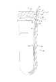
- FIG. 1 It is a partial cross section side view of a synthetic resin container which is one embodiment of the present invention. It is a top view of the synthetic resin container shown in FIG. It is a partial cross section side view of the preform before shape
- a synthetic resin container 1 according to the present embodiment (hereinafter also referred to as container 1) has an outer layer 2 and an inner layer 3 disposed inside the outer layer 2, and 2 It is formed by axial stretch blow molding.
- the container 1 is configured as a laminated peeling container having a double container structure including the outer layer 2 and the inner layer 3.
- the container 1 has a substantially cylindrical mouth 4, a shoulder 5 connected to the lower end of the mouth 4 and gradually expanding downward, and the lower end of the shoulder 5. It has the trunk
- the vertical direction means the direction along the central axis O of the mouth 4
- the upper direction means the direction from the bottom 7 to the mouth 4 (for example, the upper side in FIG. 1)
- the downward direction means the opposite direction.
- a longitudinal cross section means the cross section by the plane containing the central axis line O
- a cross section means the cross section by the plane perpendicular
- the mouth 4 has an external thread 4a for screwing the pouring cap.
- the mouth 4 may be replaced with the male screw 4a, and may be provided with a convex such as an annular shape that can be engaged with the pouring cap and the undercut shape by tapping.
- an annular neck ring 8 is provided at the lower part of the mouth 4.
- the shape of the neck ring 8 can be changed as appropriate. Further, the neck ring 8 may not be provided.
- the mouth 4 has an outside air inlet 13 for introducing outside air between the outer layer 3 and the inner layer 2. The detailed configuration of the outside air introduction port 13 will be described later.
- the shoulder 5 has a substantially conical shape concentric with the central axis O of the mouth 4 and has a curved shape having a point of inflection where the upper side is concave and the lower side is convex in the longitudinal cross section.
- the body portion 6 has a cylindrical shape concentric with the central axis O of the mouth portion 4 in which the portion extending from the vertical middle portion to the upper end portion is narrowed.
- the shape of the body 6 can be changed as appropriate.
- the body 6 may have a cylindrical shape without a neck.
- the body portion 6 may have a grooved annular rib extending in the circumferential direction.
- the bottom portion 7 has an annular ground portion 7 a concentric with the central axis O of the mouth portion 4 and a bottom panel 7 b located inside the ground portion 7 a.
- the shape of the bottom 7 can be changed as appropriate.
- the outer layer 2 is made of polyethylene terephthalate (PET) in the present embodiment. Further, the outer layer 2 constitutes the outer shell of the container 1, and the part constituting the trunk 6 is flexible due to the squeeze operation and can be restored by elastic force after deformation. It has resiliency. In addition, in the case where a container with a pump is configured by the container 1, the outer layer body 2 may not have such flexibility and restorability.
- the synthetic resin material constituting the outer layer body 2 is not limited to PET, and may be, for example, an olefin resin such as polypropylene (PP) or polyethylene (PE). Further, the outer layer body 2 is not limited to a single-layer structure, and may have a multi-layer structure capable of improving the barrier property and the like.
- the inner layer 3 is made of PET in this embodiment. Further, the inner layer body 3 is formed in a bag shape thinner than the outer layer body 2. Inside the inner layer body 3, a housing space S connected to the upper end opening 4b of the mouth 4 is formed. In the storage space S, a food such as soy sauce or a food such as a beverage, a cosmetic such as a lotion, a shampoo, a rinse, or a toiletry such as a liquid soap can be stored as a content. The contents are not limited to food, cosmetics or toiletries.
- the synthetic resin material constituting the inner layer body 3 is not limited to PET, and may be, for example, nylon or ethylene-vinyl alcohol copolymer resin (EVOH). Further, the inner layer body 3 is not limited to a single-layer structure, and may have a multi-layer structure capable of improving the barrier property and / or the content resistance.
- the synthetic resin materials constituting the outer layer body 2 and the inner layer body 3 are both PET that can be biaxially stretched.
- Examples of such biaxially stretchable PET include homoPET and the like.
- other PETs such as IPA (isophthalic acid) modified PET or CHDM modified PET may be used.
- PET which comprises the outer-layer body 2 and PET which comprises the inner-layer body 3 may differ.
- the container 1 is formed by biaxial stretch blow molding of the preform 9 shown in FIG.
- the preform 9 has an outer body 10 forming the outer layer 2 and an inner body 11 forming the inner layer 3.
- the preform 9 has a double preform structure including the outer body 10 and the inner body 11.
- the preform 9 has a port 4 having substantially the same configuration as the port 4 of the container 1 because the preform 9 is not substantially stretched at the time of biaxial stretch blow molding.
- a bottomed cylindrical (test tube) preform body 12 is connected below the mouth 4, a bottomed cylindrical (test tube) preform body 12 is connected.
- the outer body 10 has a cylindrical outer opening 10 a that constitutes the opening 4.
- An external thread 4a and a neck ring 8 are provided on the outer peripheral surface of the outer opening 10a.
- an external air introduction port 13 composed of a laterally long through hole is provided in a portion between the male screw 4a and the neck ring 8 in the outer port portion 10a.
- the outside air introduction port 13 is provided in the outer opening 10a at two places across the central axis O.
- the male screw 4a has a notch 14 immediately above the external air inlet 13, and communicates the external air intake provided in the pouring cap with the external air inlet 13 via the notch 14. Is configured. However, the male screw 4 a may not have such a notch 14.
- the outer body portion 10b has an upper portion whose thickness gradually decreases while the outer diameter gradually decreases downward, a cylindrical middle portion having a substantially constant thickness in the vertical direction, and a lower end of the middle portion And a semispherical lower portion that occludes the
- the shape of the outer body portion 10b can be changed as appropriate.
- the inner body 11 has a stepped cylindrical inner opening 11 a that constitutes the opening 4.
- the inner opening 11a has an annular flange 15 placed on the upper end of the outer opening 10a, a cylindrical upper cylinder 16 depending from the inner peripheral edge of the flange 15 and contacting the inner surface of the outer opening 10a, and It has a conical inclined cylinder 17 whose diameter decreases from the lower end of the cylinder 16 downward, and a part (a part excluding the lower part) of the cylindrical lower cylinder 18 depending from the lower end of the inclined cylinder 17.
- the upper end of the inclined cylinder 17 is located above the upper end of the pair of outside air introduction ports 13.
- the inner body portion 11b has a lower portion in the lower cylinder 18 and an upper portion including an inclined portion 19 whose outer diameter gradually reduces in diameter from the lower portion toward the lower portion and thickness becomes substantially constant in the vertical direction A cylindrical middle portion having a thickness and a hemispherical lower portion closing the lower end of the middle portion.
- the shape of the inner body portion 11b can be appropriately changed in accordance with the shape of the outer body portion 10b.
- the inner body 11 has a convex piece 20 extending in the vertical direction from the upper end of the inclined cylinder 17 to the upper part of the inclined portion 19.
- Three convex pieces 20 are provided on both sides of the axis passing through both of the pair of outside air inlets 13, and the outer layer 2 and the inner layer are provided around and under the outside air inlet 13 even after biaxial stretch blow molding. It is comprised so that the space for ventilation
- the number, arrangement, and shape of the convex pieces 20 can be changed as appropriate. Further, the configuration may be such that the convex piece 20 is not provided.
- Such a preform 9 is formed into the container 1 by biaxial stretch blow molding in which stretching in the axial direction by the stretch rod and stretching in the circumferential direction by blowing pressurized air (or liquid as a content) are performed. can do.
- the container 1 thus formed has at its shoulder 5 at least one shoulder rib 21 formed according to the shape of the cavity of the mold for blow molding.
- the container 1 has eighteen shoulder ribs 21 arranged at equal intervals in the circumferential direction of the central axis O.
- the number and arrangement of the shoulder ribs 21 can be changed as appropriate.
- Each shoulder rib 21 is concave and extends from the side of the mouth 4 toward the side of the body 6 and extends along the radial direction in top view.
- each shoulder rib 21 has a U-shaped cross-sectional shape whose width gradually narrows inward in the radial direction of the central axis O in the cross-section substantially over the entire length. Therefore, in each shoulder rib 21, the inner layer body 3 can be easily peeled off from the outer layer body 2. Further, by providing the shoulder rib 21, after the inner layer body 3 is peeled from the outer layer body 2, the inner layer body 3 hardly adheres to the outer layer body 2, so the airway between the inner layer body 3 and the outer layer body 2 Can be secured stably.
- the shoulder 5 is connected to the lower end of the opening 4, for example, the shoulder 5 is connected to the lower end of the annular step which is diameter-expanded in a step shape from the lower end of the opening 4. As compared with the configuration, it is easier to secure an airway between the outside air introduction port 13 and the trunk portion 6. However, the shoulder 5 only needs to be located below the mouth 4 and is not limited to the configuration connected to the lower end of the mouth 4.
- the shoulder 5 has a curved shape having an inflection point in which the upper side is concave and the lower side is convex in the vertical cross section, so for example, the shoulder 5 is entirely convex in the vertical cross section. It is easier to secure the airway between the outside air introduction port 13 and the trunk 6 as compared with the configuration having the curved shape.
- the shoulder portion 5 only needs to gradually expand in the downward direction, and the shape thereof can be changed as appropriate.
- At least one shoulder rib 21 extends along the radial direction of the shoulder 5 in top view, so the airway extending from the outside air introduction port 13 to the trunk 6 is shortened, and the outside air is reduced. Can be introduced smoothly.
- the at least one shoulder rib 21 is not limited to such a shape, and may extend in a direction inclined with respect to the radial direction of the shoulder 5 in top view, for example. It may have a curved shape.
- the synthetic resin container 1 ′ extends in a direction inclined with respect to the radial direction of the shoulder portion 5 in a top view and curves. You may have 18 shoulder ribs 21 'which have the following shape.
- the mouth 4, the shoulder 5 and the body 6 of the container 1 have a circular cylindrical shape in cross section, but the invention is not limited to such a configuration, for example, in cross section It may have a polygonal or elliptical cylindrical shape.
- the external air introduction port 13 consists of a through-hole which penetrates the part (outer opening 10a) which comprises the opening 4 in the outer-layer body 2, it is limited to such a thing.
- it may be formed between the part (outside opening 10a) which constitutes the mouth 4 in the outer layer 2 and the part (inner opening 11a) which constitutes the opening 4 in the inner layer 3.
- the outside air introduction port 13 is a recessed groove provided continuously from the outer peripheral edge of the flange 15 to the lower end of the upper cylinder 16 on the lower surface of the flange 15 of the inner opening 11a and the outer peripheral surface of the upper cylinder 16
- the upper groove of the outer opening 10a and the inner peripheral surface of the outer opening 10a are formed by a recessed groove continuously extending from the outer peripheral edge of the upper end of the outer opening 10a to a position beyond the lower end of the upper cylinder 16 It may be done.
- At least one shoulder rib 21 has a concave shape
- the present invention is not limited to this, and may have a convex shape.
Landscapes
- Engineering & Computer Science (AREA)
- Mechanical Engineering (AREA)
- Ceramic Engineering (AREA)
- Containers Having Bodies Formed In One Piece (AREA)
Abstract
L'invention concerne un récipient en résine synthétique (1), présentant un corps de couche externe (2) et un corps de couche interne (3), et formé par moulage par soufflage à étirage biaxial. Le récipient en résine synthétique (1) présente : une embouchure cylindrique (4) ; un épaulement (5) situé au-dessous de l'embouchure (4) et présentant un diamètre augmentant progressivement vers le bas ; un corps (6) se prolongeant depuis l'extrémité inférieure de l'épaulement (5) ; et un fond (7) fermant l'extrémité inférieure du corps (6). L'embouchure (4) présente une ouverture d'introduction d'air extérieur (13), qui introduit de l'air extérieur entre le corps de couche externe (2) et le corps de couche interne (3). L'épaulement (5) présente au moins une nervure d'épaulement (21) présentant une forme en creux ou en saillie et s'étendant depuis le côté de l'embouchure (4) vers le côté du corps (6).
Priority Applications (3)
| Application Number | Priority Date | Filing Date | Title |
|---|---|---|---|
| EP18896649.3A EP3733539A4 (fr) | 2017-12-28 | 2018-11-07 | Récipient en résine synthétique |
| CN201880083813.8A CN111511648B (zh) | 2017-12-28 | 2018-11-07 | 合成树脂制容器 |
| US16/957,877 US11472591B2 (en) | 2017-12-28 | 2018-11-07 | Synthetic resin container |
Applications Claiming Priority (4)
| Application Number | Priority Date | Filing Date | Title |
|---|---|---|---|
| JP2017254564A JP6910735B2 (ja) | 2017-12-28 | 2017-12-28 | 合成樹脂製容器、プリフォーム、及び合成樹脂製容器の製造方法 |
| JP2017-254564 | 2017-12-28 | ||
| JP2018015848A JP7094620B2 (ja) | 2018-01-31 | 2018-01-31 | 合成樹脂製容器 |
| JP2018-015848 | 2018-01-31 |
Publications (1)
| Publication Number | Publication Date |
|---|---|
| WO2019130845A1 true WO2019130845A1 (fr) | 2019-07-04 |
Family
ID=67063414
Family Applications (1)
| Application Number | Title | Priority Date | Filing Date |
|---|---|---|---|
| PCT/JP2018/041394 WO2019130845A1 (fr) | 2017-12-28 | 2018-11-07 | Récipient en résine synthétique |
Country Status (4)
| Country | Link |
|---|---|
| US (1) | US11472591B2 (fr) |
| EP (1) | EP3733539A4 (fr) |
| CN (1) | CN111511648B (fr) |
| WO (1) | WO2019130845A1 (fr) |
Cited By (1)
| Publication number | Priority date | Publication date | Assignee | Title |
|---|---|---|---|---|
| EP4029798A4 (fr) * | 2019-09-13 | 2023-10-18 | Yoshino Kogyosho Co., Ltd. | Contenant à délaminage |
Families Citing this family (2)
| Publication number | Priority date | Publication date | Assignee | Title |
|---|---|---|---|---|
| JPWO2019069794A1 (ja) * | 2017-10-06 | 2020-10-22 | 北海製罐株式会社 | 合成樹脂製多重ボトル |
| JP2023050740A (ja) | 2021-09-30 | 2023-04-11 | 株式会社吉野工業所 | 二重容器成形用プリフォーム |
Citations (11)
| Publication number | Priority date | Publication date | Assignee | Title |
|---|---|---|---|---|
| JP2000062745A (ja) * | 1998-08-13 | 2000-02-29 | Toppan Printing Co Ltd | 分離可能な多層容器 |
| JP2003192031A (ja) * | 2001-12-21 | 2003-07-09 | Kao Corp | 積層剥離容器 |
| JP2014091537A (ja) * | 2012-10-31 | 2014-05-19 | Yoshino Kogyosho Co Ltd | 積層剥離容器 |
| JP2015145249A (ja) * | 2014-01-31 | 2015-08-13 | 株式会社吉野工業所 | 積層剥離容器 |
| JP2016030630A (ja) * | 2014-07-29 | 2016-03-07 | 株式会社吉野工業所 | 積層剥離容器 |
| JP2017030773A (ja) * | 2015-07-30 | 2017-02-09 | 株式会社吉野工業所 | 二重容器 |
| JP2017100747A (ja) * | 2015-11-30 | 2017-06-08 | 株式会社吉野工業所 | 二重容器 |
| JP2017114555A (ja) * | 2015-12-25 | 2017-06-29 | 株式会社吉野工業所 | 二重容器 |
| JP2017171368A (ja) * | 2016-03-24 | 2017-09-28 | 株式会社吉野工業所 | 積層剥離容器 |
| JP2017178434A (ja) | 2016-03-31 | 2017-10-05 | 株式会社吉野工業所 | 積層剥離容器及びプリフォーム |
| JP2017214127A (ja) * | 2016-06-01 | 2017-12-07 | 株式会社吉野工業所 | 二重容器 |
Family Cites Families (14)
| Publication number | Priority date | Publication date | Assignee | Title |
|---|---|---|---|---|
| AU724022B2 (en) * | 1996-05-30 | 2000-09-07 | Yoshino Kogyosho Co., Ltd. | Extrusion blow molded container having cylindrical drum portion and mold for shaping the container |
| JP4437315B2 (ja) | 2004-12-27 | 2010-03-24 | 株式会社吉野工業所 | 合成樹脂製ブロー成形容器。 |
| JP5638915B2 (ja) * | 2010-10-29 | 2014-12-10 | 株式会社吉野工業所 | 剥離容器の製造方法 |
| EP2508318A1 (fr) * | 2011-04-07 | 2012-10-10 | Anheuser-Busch InBev NV | Préforme pour mouler un bag-in-box par soufflage, procédé de fabrication d'un bag-in-box et bag-in-box |
| JP5667010B2 (ja) * | 2011-06-09 | 2015-02-12 | 株式会社吉野工業所 | 吐出容器 |
| JP5979467B2 (ja) * | 2011-08-31 | 2016-08-24 | 株式会社吉野工業所 | 積層ブロー成形容器及び吸気孔の形成方法 |
| JP2013154907A (ja) * | 2012-01-30 | 2013-08-15 | Yoshino Kogyosho Co Ltd | ボトル |
| JP5996355B2 (ja) * | 2012-09-28 | 2016-09-21 | 株式会社吉野工業所 | 二重容器、その容器用プリフォーム、及びその容器の製造方法 |
| JP5917368B2 (ja) * | 2012-10-31 | 2016-05-11 | 株式会社吉野工業所 | 二重容器 |
| WO2014068876A1 (fr) * | 2012-10-31 | 2014-05-08 | 株式会社吉野工業所 | Double récipient |
| JP6349230B2 (ja) | 2014-10-31 | 2018-06-27 | 株式会社吉野工業所 | 積層剥離容器 |
| US10202218B2 (en) * | 2015-01-23 | 2019-02-12 | Kyoraku Co., Ltd. | Delaminatable container |
| JP6366518B2 (ja) * | 2015-01-30 | 2018-08-01 | 株式会社吉野工業所 | スクイズフォーマー容器 |
| JP6534329B2 (ja) * | 2015-09-30 | 2019-06-26 | 株式会社吉野工業所 | 二重容器 |
-
2018
- 2018-11-07 WO PCT/JP2018/041394 patent/WO2019130845A1/fr unknown
- 2018-11-07 EP EP18896649.3A patent/EP3733539A4/fr active Pending
- 2018-11-07 US US16/957,877 patent/US11472591B2/en active Active
- 2018-11-07 CN CN201880083813.8A patent/CN111511648B/zh active Active
Patent Citations (11)
| Publication number | Priority date | Publication date | Assignee | Title |
|---|---|---|---|---|
| JP2000062745A (ja) * | 1998-08-13 | 2000-02-29 | Toppan Printing Co Ltd | 分離可能な多層容器 |
| JP2003192031A (ja) * | 2001-12-21 | 2003-07-09 | Kao Corp | 積層剥離容器 |
| JP2014091537A (ja) * | 2012-10-31 | 2014-05-19 | Yoshino Kogyosho Co Ltd | 積層剥離容器 |
| JP2015145249A (ja) * | 2014-01-31 | 2015-08-13 | 株式会社吉野工業所 | 積層剥離容器 |
| JP2016030630A (ja) * | 2014-07-29 | 2016-03-07 | 株式会社吉野工業所 | 積層剥離容器 |
| JP2017030773A (ja) * | 2015-07-30 | 2017-02-09 | 株式会社吉野工業所 | 二重容器 |
| JP2017100747A (ja) * | 2015-11-30 | 2017-06-08 | 株式会社吉野工業所 | 二重容器 |
| JP2017114555A (ja) * | 2015-12-25 | 2017-06-29 | 株式会社吉野工業所 | 二重容器 |
| JP2017171368A (ja) * | 2016-03-24 | 2017-09-28 | 株式会社吉野工業所 | 積層剥離容器 |
| JP2017178434A (ja) | 2016-03-31 | 2017-10-05 | 株式会社吉野工業所 | 積層剥離容器及びプリフォーム |
| JP2017214127A (ja) * | 2016-06-01 | 2017-12-07 | 株式会社吉野工業所 | 二重容器 |
Non-Patent Citations (1)
| Title |
|---|
| See also references of EP3733539A4 |
Cited By (1)
| Publication number | Priority date | Publication date | Assignee | Title |
|---|---|---|---|---|
| EP4029798A4 (fr) * | 2019-09-13 | 2023-10-18 | Yoshino Kogyosho Co., Ltd. | Contenant à délaminage |
Also Published As
| Publication number | Publication date |
|---|---|
| CN111511648B (zh) | 2022-07-05 |
| EP3733539A4 (fr) | 2021-11-03 |
| US11472591B2 (en) | 2022-10-18 |
| CN111511648A (zh) | 2020-08-07 |
| US20200339300A1 (en) | 2020-10-29 |
| EP3733539A1 (fr) | 2020-11-04 |
Similar Documents
| Publication | Publication Date | Title |
|---|---|---|
| US11383875B2 (en) | Double container | |
| JP6808339B2 (ja) | 積層剥離容器及びプリフォーム | |
| WO2019130845A1 (fr) | Récipient en résine synthétique | |
| US11873132B2 (en) | Double container | |
| JP7094620B2 (ja) | 合成樹脂製容器 | |
| JP7204303B2 (ja) | 二重容器及びその製造方法 | |
| WO2020195688A1 (fr) | Ensemble préforme, récipient à liquide à double paroi et procédé de fabrication de récipient à liquide à double paroi | |
| JP7282463B2 (ja) | 二重容器、プリフォーム組立体、プリフォーム組立体の製造方法及び二重容器の製造方法 | |
| CN111225856B (zh) | 双层容器 | |
| JP7098232B2 (ja) | 積層剥離容器 | |
| JP2023041869A (ja) | 積層剥離容器 | |
| JP7399557B2 (ja) | 二重容器及び二重容器の製造方法 | |
| KR20220039804A (ko) | 적층 박리 용기 | |
| JP2020193007A (ja) | 積層剥離容器 | |
| JP7337445B2 (ja) | 積層剥離容器 | |
| JP2023035227A (ja) | 積層剥離容器 | |
| JP7317454B2 (ja) | 積層剥離容器 | |
| WO2021199925A1 (fr) | Récipient de délaminage | |
| JP2022086878A (ja) | 積層剥離容器 | |
| JP2023111718A (ja) | 積層剥離容器 | |
| JP2021133971A (ja) | 積層剥離容器 | |
| JP2023111714A (ja) | 積層剥離容器 | |
| JP2022117220A (ja) | プリフォーム組立体及び積層剥離容器 | |
| JP2021054447A (ja) | 積層剥離容器 |
Legal Events
| Date | Code | Title | Description |
|---|---|---|---|
| 121 | Ep: the epo has been informed by wipo that ep was designated in this application |
Ref document number: 18896649 Country of ref document: EP Kind code of ref document: A1 |
|
| NENP | Non-entry into the national phase |
Ref country code: DE |
|
| ENP | Entry into the national phase |
Ref document number: 2018896649 Country of ref document: EP Effective date: 20200728 |