WO2019123527A1 - Dispositif de saisie et de placement, dispositif de détection, et procédé de détection - Google Patents
Dispositif de saisie et de placement, dispositif de détection, et procédé de détection Download PDFInfo
- Publication number
- WO2019123527A1 WO2019123527A1 PCT/JP2017/045468 JP2017045468W WO2019123527A1 WO 2019123527 A1 WO2019123527 A1 WO 2019123527A1 JP 2017045468 W JP2017045468 W JP 2017045468W WO 2019123527 A1 WO2019123527 A1 WO 2019123527A1
- Authority
- WO
- WIPO (PCT)
- Prior art keywords
- packing
- mounting
- pitch
- reference pattern
- unit
- Prior art date
Links
Images

Classifications
-
- H—ELECTRICITY
- H05—ELECTRIC TECHNIQUES NOT OTHERWISE PROVIDED FOR
- H05K—PRINTED CIRCUITS; CASINGS OR CONSTRUCTIONAL DETAILS OF ELECTRIC APPARATUS; MANUFACTURE OF ASSEMBLAGES OF ELECTRICAL COMPONENTS
- H05K13/00—Apparatus or processes specially adapted for manufacturing or adjusting assemblages of electric components
- H05K13/02—Feeding of components
-
- H—ELECTRICITY
- H05—ELECTRIC TECHNIQUES NOT OTHERWISE PROVIDED FOR
- H05K—PRINTED CIRCUITS; CASINGS OR CONSTRUCTIONAL DETAILS OF ELECTRIC APPARATUS; MANUFACTURE OF ASSEMBLAGES OF ELECTRICAL COMPONENTS
- H05K13/00—Apparatus or processes specially adapted for manufacturing or adjusting assemblages of electric components
- H05K13/04—Mounting of components, e.g. of leadless components
- H05K13/0417—Feeding with belts or tapes
- H05K13/0419—Feeding with belts or tapes tape feeders
-
- H—ELECTRICITY
- H05—ELECTRIC TECHNIQUES NOT OTHERWISE PROVIDED FOR
- H05K—PRINTED CIRCUITS; CASINGS OR CONSTRUCTIONAL DETAILS OF ELECTRIC APPARATUS; MANUFACTURE OF ASSEMBLAGES OF ELECTRICAL COMPONENTS
- H05K13/00—Apparatus or processes specially adapted for manufacturing or adjusting assemblages of electric components
- H05K13/08—Monitoring manufacture of assemblages
Definitions
- the present specification discloses a mounting device, a detection device, and a detection method.
- the invention disclosed in this specification has been made in view of such problems, and has as its main object to provide a mounting device, a detection device, and a detection method that can more reliably determine the packing pitch of parts. .
- the mounting apparatus, the detection apparatus, and the detection method of the present disclosure employ the following means in order to achieve the above-described main object.
- the mounting device disclosed in the present specification is A mounting unit for mounting a supply unit for feeding components by feeding out a packing member in which the components are packed at predetermined intervals; A mounting head for collecting the part from the packaging member; An imaging unit configured to image the packaging member; Acquires a reference pattern of a packing member in which the part is packed based on the pre-collection image obtained by imaging the packing member before collecting the part and the collected image obtained by imaging the packing member after collecting the part A control unit for determining the packing pitch of the parts based on the reference pattern; Is provided.
- the reference pattern of the packaging member in which the component is packaged is acquired based on the pre-collection image obtained by imaging the packaging member before collecting the component and the post-collection image obtained by imaging the packaging member after collecting the component. Then, the packing pitch of the parts is determined based on this reference pattern.
- this mounting apparatus it is possible to detect the area of the component using the pre-extraction image and the post-collection image, and since the packing position of the component can be grasped more reliably, the packing pitch of the component is more reliable. Can be asked.
- a "packaging member” a tape etc. is mentioned, The thing by which components were stuck on the tape, and the thing by which components were accommodated in the accommodating part formed in the tape etc. are mentioned as a packing method.
- FIG. 1 is a schematic explanatory view showing an example of a mounting system 10.
- FIG. 1 is a schematic explanatory view of a mounting system 10 which is an example of the present disclosure.
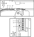
- FIG. 2 is an explanatory view of the feeder 16 and the packing member 30.
- the mounting system 10 is, for example, a system that executes a process of mounting the component P on the substrate S.
- the mounting system 10 includes a mounting device 11 and a host computer (PC) 40.
- the mounting system 10 is configured as a mounting line in which a plurality of mounting apparatuses 11 for performing mounting processing for mounting the component P on the substrate S are disposed from the upstream to the downstream. Only one mounting device 11 is shown in FIG. 1 for the convenience of description.
- the left-right direction (X axis), the front-rear direction (Y axis), and the up-down direction (Z axis) are as shown in FIGS.
- the mounting device 11 includes a substrate processing unit 12, a mounting unit 13, a component supply unit 14, a parts camera 17, a control device 25, and an operation panel 28.
- the substrate processing unit 12 is a unit for carrying in, transporting, fixing the substrate S at a mounting position, and carrying out the substrate S.
- the substrate processing unit 12 has a pair of conveyor belts provided at intervals in the front and back of FIG. 1 and bridged in the left-right direction. The substrate S is transported by this conveyor belt.
- the mounting unit 13 is a unit for collecting the component P from the component supply unit 14 and arranging the component P on the substrate S fixed to the substrate processing unit 12.
- the mounting unit 13 includes a head moving unit 20, a mounting head 21, and a suction nozzle 22 (collection member).
- the head moving unit 20 includes a slider that is guided by a guide rail and moves in the X and Y directions, and a motor that drives the slider.
- the mounting head 21 picks up a plurality of parts P and moves the head moving unit 20 in the X and Y directions.
- the mounting head 21 is removably mounted on the slider.
- One or more suction nozzles 22 are detachably mounted on the lower surface of the mounting head 21.
- a plurality of suction nozzles 22 for picking up the component P can be mounted on the circumference.
- the suction nozzle 22 picks up components using negative pressure.
- the collection of the part P may be performed by a mechanical chuck or the like that mechanically holds the part P in addition to the suction nozzle 22.
- a mark camera 23 is disposed on the lower surface side of the mounting head 21. The mark camera 23 moves in the XY directions along with the movement of the mounting head 21 and picks up the mark formed on the substrate S, and also picks up the sampling position of the component supply unit 14.
- the component supply unit 14 is a unit that supplies the component P to the mounting unit 13 by delivering the packaging member 30 (for example, a tape or the like) in which the components P are packaged at a predetermined interval (packing pitch).
- the component supply unit 14 is detachably attached to the front side of the mounting apparatus 11 via the mounting unit 15 with a plurality of feeders 16 mounted with reels.
- a packaging member 30 is wound around each reel, and a plurality of parts P are packaged along the longitudinal direction of the packaging member 30 on the packaging member 30.
- the packing member 30 is formed with a feed hole 31 and a housing portion 32. In the feed holes 31, the teeth of the sprockets disposed in the feeder 16 are inserted.
- the packing member 30 is fed out by the rotational drive of this sprocket.
- the accommodating portion 32 is a space formed in the tape, and the component P is accommodated therein.
- the packing member 30 is unwound from the reel toward the rear, and is fed by the feeder 16 to a sampling position where the suction nozzle 22 sucks the component P in a state where the component P is exposed.
- the feeder 16 is provided with a controller (not shown). The controller stores the feed amount (packing pitch) of the packing member 30 and controls the drive motor of the sprocket.
- the parts camera 17 is an apparatus for capturing an image of one or more parts P collected and held by the mounting head 21 as shown in FIG.
- the parts camera 17 is disposed between the parts supply unit 14 and the substrate processing unit 12.
- the imaging range of the parts camera 17 is above the parts camera 17.
- the parts camera 17 picks up one or more images when the mounting head 21 holding the part P passes above the parts camera 17, and outputs the picked-up image to the control device 25.
- the control device 25 can detect whether or not the part P has been collected from the packaging member 30 based on the image captured by the part camera 17.
- the control device 25 is configured as a microprocessor centering on the CPU 26, and includes a storage unit 27 that stores various data.
- the control device 25 outputs control signals to the substrate processing unit 12, the mounting unit 13, the component supply unit 14, the parts camera 17 and the operation panel 28, and the mounting unit 13, the component supply unit 14, the parts camera 17 and the operation panel 28. Input the signal from.
- the storage unit 27 stores mounting condition information including the arrangement order, the arrangement position, and the like for mounting the component P on the substrate S.
- the operation panel 28 receives an input from a worker, reports information to the worker, and has a display unit and an operation unit.
- the host PC 40 is a computer that manages information of each device of the mounting system 10.
- the host PC 40 transmits mounting condition information and the like to the mounting apparatus 11, and receives a mounting processing result and the like from the mounting apparatus 11.
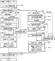
- FIG. 3 is a flowchart showing an example of the packing pitch detection routine executed by the CPU 26 of the control device 25.
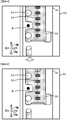
- FIG. 4 is an explanatory diagram of the pre-collection image 50 (FIG. 4A) of the part P and the post-collection image 51 (FIG. 4B) of the part P.
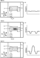
- 5A and 5B are explanatory diagrams for obtaining the reference pattern 54 without sending out the packing member 30,
- FIG. 5A is an explanatory diagram before the collection of the part P
- FIG. 5B is an explanatory diagram after the collection of the part P, and
- FIG. 5A is an explanatory diagram before the collection of the part P
- FIG. 5B is an explanatory diagram after the collection of the part P
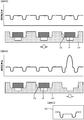
- FIG. 5 is an explanatory view of an example of a reference pattern 54.
- 6A and 6B are schematic explanatory views for sending out the packaging member 30 to obtain a reference pattern
- FIG. 6A is a pre-collection image 50 without the storage unit 32 in the imaging region
- FIG. 6C is an explanatory diagram of a post-collection image 51 of the storage unit 32 after collection of the part P.
- this mounting apparatus 11 when a plurality of storage units 32 are included in one image by imaging of the mark camera 23, the packing pitch is determined by packing member fixing detection that does not send out the packing members 30, and one storage unit 32 is included in one image.
- a first process for obtaining the packing pitch using the captured images before and after picking up the part P and a second process for obtaining the packing pitch without picking up the part P are based on predetermined settings. Switch and execute.
- the packing pitch detection routine is stored in the storage unit 27 and executed by an instruction of the worker after the feeder 16 is mounted on the component supply unit 14.
- the CPU 26 acquires information stored in the feeder 16 (S100).
- the CPU 26 acquires, for example, identifiers of the feeder 16, the packing member 30, and the part P, the feed amount (packing pitch) of the packing member 30 which has been set, and the like from the feeder 16.
- the CPU 26 determines whether or not it is the packing member fixing detection based on the acquired information (S110).
- the CPU 26 detects which of the packing member fixing detection and the packing member delivery detection depending on whether or not the plurality of storage portions 32 are imaged in one captured image based on the acquired type of the feeder 16 and the information of the packing member 30. Determine what to do.
- the CPU 26 performs packing member fixation detection, and the processing set is the first processing or the second processing It is determined whether it is (S120).
- the set processing is the first processing for obtaining the packing pitch using captured images before and after the collection of the part P
- the CPU 26 moves the mounting head 21 above the feeder 16 to collect the part P before collecting the part P.
- the packing member 30 is imaged by the mark camera 23 as the pre-collection image 50 (S130, see FIG. 4A).
- the CPU 26 causes the mounting head 21 to extract the part P (S140), and the part camera 17 picks up an image of the mounting head 21 to determine whether the part P is collected by the mounting head 21 based on the captured image.
- the “minimum standard pitch” may be the shortest pitch (for example, 1 mm, 2 mm, etc.) of the packing intervals of various packing members 30 used in the mounting apparatus 11.
- the CPU 26 moves the mounting head 21 to the upper side of the feeder 16 and causes the mark camera 23 to pick up the packaging member 30 after picking up the parts P as a picked up image 51 (S160, FIG. 4B reference).
- the CPU 26 acquires a reference pattern of the packing member 30 based on the pre-collection image 50 and the post-collection image 51 (S170). For example, as shown in FIG. 5, the CPU 26 extracts the area of the part P from the difference between the pre-collection image 50 and the after-collection image 51, and determines that the area near the part P is the storage unit 32 It can be a pattern. As shown to FIG.
- the CPU 26 integrates the luminances of the plurality of columns of the before-collection image 50 and adds or multiplies the luminances of the plurality of columns of the after-sampling image 51 to acquire the reference pattern It is also possible to As shown by the dotted line in FIG.
- the value of black can be set to a value of 900 if the luminance of black is 30. It can be done more accurately.
- the CPU 26 performs fitting processing of the reference pattern 54 on the area of the pre-collection image 50 or the after-collection image 51 to obtain a packing pitch (S180).
- the CPU 26 determines the packing pitch from the intervals of the plurality of areas that conform to the reference pattern included in the captured image of the packing member 30. For example, the CPU 26 may perform fitting of the reference pattern 54 on each area of the luminance integrated value shown in FIG. 5. Thus, the packing pitch of the packing member 30 can be obtained as an actual measurement value.
- the CPU 26 causes the mark camera 23 to capture the before-collection image 50 (S190)
- step S170 a reference pattern is acquired from the pre-collection image 50.
- the CPU 26 acquires, for example, the luminance distribution of the collection position in the pre-collection image 50 as a reference pattern.
- the processing time can be shortened, but the accuracy is inferior to that in the first process.
- the mounting apparatus 11 is configured to allow the user to select either the first process or the second process in consideration of the advantages and disadvantages.
- the CPU 26 determines the packing pitch by fitting with the reference pattern in S180, as described above.
- the CPU 26 performs package member delivery detection, and the processing set is the first It is determined whether it is a process or a second process (S200). In the following processing, the same processing as the above-described processing for detecting the fixing of the packing member is performed, and the specific description is omitted.
- the set processing is the first processing
- the CPU 26 causes the mark camera 23 to capture the before-collection image 50 (see S210, FIGS. 6A and 6B).
- the CPU 26 causes the mounting head 21 to collect the component P (S220), and recognizes whether the component P is collected by the mounting head 21 (S230).
- the CPU 26 causes the packaging member 30 to be sent out by the minimum standard pitch (S240), and executes the processing of S210 to S230. For example, even if the container 32 is not at the collection position immediately after the feeder 16 is mounted, the container 32 is sent out to the collection position if this process is repeated.
- the CPU 26 causes the mark camera 23 to pick up the image 51 after sampling (S250, see FIG. 6C).
- the CPU 26 acquires a reference pattern of the packaging member 30 based on the pre-collection image 50 and the post-collection image 51 (S260). This reference pattern can be acquired by the same processing as S170.
- the CPU 26 sends out the packing member 30 by the minimum standard pitch and captures an image of the packing member 30, and performs fitting processing with the reference pattern to obtain a packing pitch (S270).
- the CPU 26 causes the packing member 30 to be sent out by the minimum specified pitch, causes the packing member 30 to be imaged, and repeats the process of determining whether the reference pattern is included in the captured image.
- the packing pitch is determined from the feed amount up to this detection time.
- the packing pitch of the packing member 30 can be obtained as an actual measurement value.
- the CPU 26 causes the mark camera 23 to capture the pre-collection image 50 (S280), and acquires a reference pattern from the pre-collection image 50 in S260.
- the CPU 26 acquires, for example, the luminance distribution of the collection position in the pre-collection image 50 (FIG. 6B) as a reference pattern.
- the CPU 26 determines the packing pitch by fitting with the reference pattern in S270, as described above.
- the CPU 26 stores the obtained packing pitch, and when the packing pitch is different from that set in the feeder 16, notifies the worker of information to that effect (S290), and this routine is executed. finish.
- the CPU 26 may display a message and a warning on the display unit of the operation panel 28.
- the packing member 30 in which the parts P are packed plural kinds of packing pitch may exist.
- the packaging member 30 is attached to the feeder 16, if the packaging pitch is incorrectly input, a large number of component losses may occur during the mounting process. In this mounting device 11, such packing loss can be prevented because the packing pitch is automatically measured.
- the operator who has confirmed the notified content may perform processing to change the packing pitch obtained by the mounting device 11.
- the CPU 26 may transmit the packing pitch to the feeder 16 for updating.
- the mounting device 11 causes the packaging member 30 to be sent out by the amount of feed of the obtained packing pitch, and causes the mounting head 21 to extract the component P from the packing member 30 according to the arrangement order of the components P included in the mounting condition information. Run.
- the mounting head 21 of this embodiment corresponds to the mounting head of the present disclosure
- the mounting unit 15 corresponds to the mounting unit
- the feeder 16 corresponds to the supply unit
- the mark camera 23 corresponds to the imaging unit
- the CPU 26 is the control unit.
- the part camera 17 and the control device 25 correspond to the recognition unit
- the operation panel 28 corresponds to the notification unit
- the control device 25 corresponds to the inspection device.
- the before-collection image 50 obtained by imaging the packing member 30 before the extraction of the part P and the after-collection image 51 obtained by imaging the packing member 30 after the extraction of the part P Based on the reference pattern of the packing member 30 in which the part P is packed, the packing pitch of the part P is obtained based on the reference pattern.
- the mounting device 11 can detect the area of the part P using the pre-collection image 50 and the after-collection image 51, and can more reliably grasp the packing position of the part P.
- the packing pitch of can be determined more reliably.
- the control device 25 determines the packing pitch from the intervals of a plurality of areas conforming to the reference pattern included in the image obtained by imaging the packaging member 30. .
- the packing pitch of the component P can be determined more reliably using the captured image.
- the control device 25 sends out the packing member 30 by a standard pitch to cause the packing member 30 to be imaged, and repeatedly determines whether the reference image is included in the captured image.
- the packing pitch is determined from the feed amount up to this detection time.
- the packing pitch of the component P can be determined more reliably by using one or more captured images picked up by feeding out the packing member 30.
- control device 25 integrates the luminances of a plurality of columns of the before-collection image 50 and integrates the luminances of a plurality of columns of the after-sampling image 51 to acquire a reference pattern, and integrates the luminances of a plurality of columns of the captured image. It is determined whether a reference pattern is included in this captured image.
- the packing positions of the packing member 30, the parts P, the parts P, etc. are often in the same system color (for example, black or gray) and it may be difficult to distinguish. In this mounting apparatus 11, for example, multiple exposure etc.
- the method can be used to integrate the luminances of a plurality of columns so that their differences can be made clearer, so that the packing pitch of parts can be determined more reliably.
- control device 25 performs a first process of determining the packing pitch based on the reference pattern acquired from the pre-collection image 50 and the post-collection image 51, and the standard acquired from the pre-collection image 50 without using the post-collection image 51.
- One of the second processing for determining the packing pitch based on the pattern is performed.
- the mounting apparatus 11 can execute either the first process of obtaining the packing pitch more reliably or the second process of simplifying the process.
- the mounting process can be performed at an accurate packing pitch by notifying the operator of the calculated packing pitch via the operation panel 28.
- the control device 25 causes the packing member 30 to be sent out to the feeder 16 by the feeding amount of the packing pitch, and causes the mounting head 21 to extract the component P from the packing member 30.
- the mounting apparatus 11 by more reliably determining the packing pitch of the parts P, it is possible to execute the mounting process more reliably.
- the present invention is not particularly limited to this, and only the first process may be performed. Also in this mounting apparatus, the packing pitch of the parts P can be determined more reliably. Further, in the embodiment described above, the packing member fixing detection and the packing member feeding detection are switched and executed, but only one of them may be performed. In this mounting apparatus, the above-described effects of the adopted aspect can be obtained.
- the reference pattern is acquired by integrating the luminances of a plurality of columns
- the invention is not particularly limited thereto, and integration of the luminances of a plurality of columns may not be performed.
- the color tone of the part P and the packing member 30 is different, the area of the part P can be determined, so the packing pitch of the part P can be determined more reliably.
- the collection of the part P is recognized by the part camera 17, it is not particularly limited as long as it is possible to detect that the part P is collected from the packaging member 30.
- the collection of the component P may be recognized by an imaging unit that captures an image from the side of the head 21. Furthermore, when the image pickup unit for picking up an image from the side of the mounting head 21 is provided in the mounting head 21 itself, the mounting head 21 is used to recognize whether the component P is taken by the mounting head 21 or not. Since it is not necessary to move from the component supply unit 14 to the part camera 17 or another imaging unit provided outside the mounting head 21, the collection of the component P can be recognized rapidly.
- the mounting apparatus 11 may omit the extraction recognition of the part P. For example, when there is a difference between the pre-collection image 50 and the post-collection image 51, the collection of the part P may be recognized.
- the packing pitch obtained is notified to the operator by the operation panel 28, but this may be omitted.
- the mounting apparatus 11 may automatically update the packing pitch of the feeder 16 to a correct value. The mounting device 11 can execute the mounting process more reliably.
- the present disclosure has been described as the mounting apparatus 11 in the embodiment described above, a control method of the mounting apparatus 11 or a program for realizing the control method may be used.
- the present disclosure may be a detection device including the control device 25 or may be a detection method or a program thereof.
- the detection device may be provided in the host PC 40 or may be a device dedicated to inspection of the packing member 30.
- the control unit conforms to the reference pattern included in the image obtained by imaging the packaging member after acquiring the reference pattern from the image before collection and the image after collection.
- the packing pitch may be obtained from intervals of a plurality of areas. In this mounting apparatus, for example, when a plurality of packing positions of components are included in one captured image, the packing pitch of the components can be determined more reliably using the captured images.
- the control unit is a process of sending out the packing member by a standard pitch after capturing the reference pattern, imaging the packing member, and determining whether the reference image is included in the captured image.
- the packing pitch may be determined from the feed amount up to the detection time.
- the packing pitch of components can be calculated
- the “standard pitch” may be the shortest pitch among the packing intervals of various packing members used in the mounting apparatus.
- the control unit integrates the luminances of the plurality of columns of the pre-collection image and integrates the luminances of the plurality of columns of the post-collection image to acquire the reference pattern
- the luminances of the pixels may be integrated to determine whether the reference pattern is included in the captured image.
- Packing members, parts, and packing positions of parts are often in the same system color (for example, black or gray), which may be difficult to determine, but in this mounting apparatus, the luminances of a plurality of columns are integrated. Since it is possible to make those differences clearer, the packing pitch of the parts can be determined more reliably.
- the control unit performs a first process of determining the packing pitch based on a reference pattern acquired from the pre-collection image and the post-collection image, and the collection without using the after-collection image Either of the second processing for obtaining the packing pitch may be executed based on the reference pattern acquired from the previous image.
- this mounting apparatus it is possible to execute either the first process for obtaining the packing pitch more reliably or the second process for simplifying the process.
- the mounting apparatus of the present disclosure includes a recognition unit that recognizes a component collected by the mounting head, and the control unit sets the captured image after the collection of the component is confirmed by the recognition unit as the post-collection image.
- the reference pattern may be acquired.
- the packing pitch of the components can be determined more reliably because the components collected by the mounting head are confirmed.
- the mounting apparatus of the present disclosure may include a notification unit that notifies information to an operator, and the control unit may notify the operator of the determined packing pitch to the notification unit.
- the mounting process can be performed at an accurate packing pitch by notifying the operator of the obtained packing pitch.
- the control unit obtains the packing pitch, and then causes the packing member to feed the packing member by the feeding amount of the packing pitch, and the mounting head extracts the component from the packing member. It is also possible to In this mounting apparatus, more reliable mounting processing can be performed by more reliably determining the packing pitch of components.
- the detection device disclosed in the present specification is A mounting unit for mounting a supply unit for feeding components by feeding out a packing member in which components are packed at predetermined intervals, a mounting head for collecting the components from the packing member, and an imaging unit for imaging the packing member
- a detection device used for the mounting device Acquires a reference pattern of a packing member in which the part is packed based on the pre-collection image obtained by imaging the packing member before collecting the part and the collected image obtained by imaging the packing member after collecting the part
- this detection device can detect the area of the component using the pre-collection image and the post-collection image, so the packing pitch of the component can be determined more reliably.
- this detection method the process performed by any one of the mounting devices described above may be added, or the configuration of any of the mounting devices described above may be adopted.
- the detection method disclosed herein is: A mounting unit for mounting a supply unit for feeding components by feeding out a packing member in which components are packed at predetermined intervals, a mounting head for collecting the components from the packing member, and an imaging unit for imaging the packing member A detection method used for the mounting device, (A) A standard for a packaging member in which the part is packaged based on a pre-collection image obtained by imaging the packaging member before collecting the part and a post-collection image obtained by imaging the packaging member after the part is collected Obtaining a pattern, (B) determining a packing pitch of the part based on the acquired reference pattern; Is included.
- the packing pitch of the component can be determined more reliably.
- step processing for executing the processing of any of the mounting devices described above may be added, or the configuration of any of the mounting devices described above may be adopted.
- the mounting apparatus, the detection apparatus, and the detection method of the present disclosure can be used in the field of mounting electronic components.
- Reference Signs List 10 mounting system 11 mounting apparatus, 12 substrate processing unit, 13 mounting unit, 14 component supply unit, 15 mounting unit, 16 feeder, 17 parts camera, 20 head moving unit, 21 mounting head, 22 suction nozzle, 23 mark camera, Reference Signs List 25 control unit, 26 CPU, 27 storage unit, 28 operation panel, 30 packing members, 31 feed holes, 32 accommodation units, 40 host PC, 50 images before collection, 51 images after collection, 54 reference patterns, P parts, S boards .
Landscapes
- Engineering & Computer Science (AREA)
- Manufacturing & Machinery (AREA)
- Microelectronics & Electronic Packaging (AREA)
- Supply And Installment Of Electrical Components (AREA)
Abstract
La présente invention concerne un dispositif de saisie et de placement qui comprend : une unité de chargement sur laquelle une unité de distribution doit être chargée, ladite unité de distribution étant destinée à distribuer un élément d'emballage sur lequel sont emballés des composants à un intervalle prédéterminé et fournir les composants ; une tête de saisie et de placement permettant de saisir un composant à partir de l'élément d'emballage ; une unité d'imagerie permettant de capturer une image de l'élément d'emballage ; et une unité de commande permettant d'acquérir un motif de référence pour l'élément d'emballage sur lequel sont emballés les composants conditionnés sur la base d'une image de pré-capture de l'élément d'emballage avant la saisie et d'une image de post-capture de l'élément d'emballage après la saisie et déterminer un pas d'emballage de composant sur la base du motif de référence.
Priority Applications (7)
| Application Number | Priority Date | Filing Date | Title |
|---|---|---|---|
| EP17935717.3A EP3731615A4 (fr) | 2017-12-19 | 2017-12-19 | Dispositif de saisie et de placement, dispositif de détection, et procédé de détection |
| JP2019559891A JP6882522B2 (ja) | 2017-12-19 | 2017-12-19 | 実装装置、検出装置及び検出方法 |
| PCT/JP2017/045468 WO2019123527A1 (fr) | 2017-12-19 | 2017-12-19 | Dispositif de saisie et de placement, dispositif de détection, et procédé de détection |
| US16/955,109 US11382247B2 (en) | 2017-12-19 | 2017-12-19 | Mounting device, detection device, and detection method |
| CN201780097243.3A CN111406448B (zh) | 2017-12-19 | 2017-12-19 | 安装装置、检测装置及检测方法 |
| JP2021078301A JP7365376B2 (ja) | 2017-12-19 | 2021-05-06 | 実装装置及び検出方法 |
| JP2021093694A JP2021122072A (ja) | 2017-12-19 | 2021-06-03 | 実装装置及び検出方法 |
Applications Claiming Priority (1)
| Application Number | Priority Date | Filing Date | Title |
|---|---|---|---|
| PCT/JP2017/045468 WO2019123527A1 (fr) | 2017-12-19 | 2017-12-19 | Dispositif de saisie et de placement, dispositif de détection, et procédé de détection |
Publications (1)
| Publication Number | Publication Date |
|---|---|
| WO2019123527A1 true WO2019123527A1 (fr) | 2019-06-27 |
Family
ID=66994044
Family Applications (1)
| Application Number | Title | Priority Date | Filing Date |
|---|---|---|---|
| PCT/JP2017/045468 WO2019123527A1 (fr) | 2017-12-19 | 2017-12-19 | Dispositif de saisie et de placement, dispositif de détection, et procédé de détection |
Country Status (5)
| Country | Link |
|---|---|
| US (1) | US11382247B2 (fr) |
| EP (1) | EP3731615A4 (fr) |
| JP (3) | JP6882522B2 (fr) |
| CN (1) | CN111406448B (fr) |
| WO (1) | WO2019123527A1 (fr) |
Cited By (2)
| Publication number | Priority date | Publication date | Assignee | Title |
|---|---|---|---|---|
| JPWO2021166230A1 (fr) * | 2020-02-21 | 2021-08-26 | ||
| JP2021122072A (ja) * | 2017-12-19 | 2021-08-26 | 株式会社Fuji | 実装装置及び検出方法 |
Families Citing this family (2)
| Publication number | Priority date | Publication date | Assignee | Title |
|---|---|---|---|---|
| CN111998815A (zh) * | 2020-07-29 | 2020-11-27 | 北京浪潮数据技术有限公司 | Pcb板上器件之间pad间距的检测方法及相关装置 |
| JPWO2023008462A1 (fr) | 2021-07-27 | 2023-02-02 |
Citations (7)
| Publication number | Priority date | Publication date | Assignee | Title |
|---|---|---|---|---|
| JP2005539370A (ja) * | 2002-05-24 | 2005-12-22 | デラウェア キャピタル フォーメーション インク | 自動装填式コンポーネントテープフィーダ |
| US20080004746A1 (en) * | 2006-06-30 | 2008-01-03 | Jahnke Duane B | Live tape position sensor |
| JP2010171208A (ja) | 2009-01-22 | 2010-08-05 | Hitachi High-Tech Instruments Co Ltd | 電子部品装着方法及び電子部品装着装置 |
| JP2012238777A (ja) * | 2011-05-13 | 2012-12-06 | Fuji Mach Mfg Co Ltd | 部品ピッチ計測装置及び部品ピッチ計測方法 |
| JP2016031959A (ja) | 2014-07-28 | 2016-03-07 | パナソニックIpマネジメント株式会社 | 部品実装装置および部品実装方法 |
| WO2016056099A1 (fr) * | 2014-10-09 | 2016-04-14 | 富士機械製造株式会社 | Procédé de détermination et dispositif de détermination |
| JP2017130482A (ja) * | 2016-01-18 | 2017-07-27 | ヤマハ発動機株式会社 | ピッチ測定装置、ピッチ測定方法および部品実装装置 |
Family Cites Families (15)
| Publication number | Priority date | Publication date | Assignee | Title |
|---|---|---|---|---|
| JP2002176290A (ja) | 2000-12-08 | 2002-06-21 | Matsushita Electric Ind Co Ltd | 部品供給装置、部品供給方法、並びに部品実装装置 |
| JP3989728B2 (ja) * | 2001-12-28 | 2007-10-10 | 富士機械製造株式会社 | 吸着ノズル先端位置検出方法および吸着ノズル先端位置検出用補助器具セット |
| US20060075631A1 (en) * | 2004-10-05 | 2006-04-13 | Case Steven K | Pick and place machine with improved component pick up inspection |
| JP4834703B2 (ja) * | 2008-08-22 | 2011-12-14 | ヤマハ発動機株式会社 | 表面実装機 |
| JP5524495B2 (ja) * | 2009-03-10 | 2014-06-18 | 富士機械製造株式会社 | 撮像システムおよび電子回路部品装着機 |
| JP5338773B2 (ja) * | 2010-08-26 | 2013-11-13 | パナソニック株式会社 | 部品実装用装置および撮像用の照明装置ならびに照明方法 |
| JP5940243B2 (ja) * | 2010-12-28 | 2016-06-29 | ヤマハ発動機株式会社 | 電子部品装着装置及び電子部品装着方法 |
| JP4922460B2 (ja) * | 2011-02-02 | 2012-04-25 | 株式会社日立ハイテクインスツルメンツ | 電子部品装着装置 |
| JP5877314B2 (ja) * | 2012-05-08 | 2016-03-08 | パナソニックIpマネジメント株式会社 | 電子部品実装システムおよび電子部品実装方法 |
| JP6001382B2 (ja) * | 2012-08-27 | 2016-10-05 | ヤマハ発動機株式会社 | テープフィーダの選定ユニット、表面実装機、並びにテープフィーダ |
| JP2015204377A (ja) * | 2014-04-14 | 2015-11-16 | 株式会社日立製作所 | 処理装置 |
| JP6587086B2 (ja) * | 2014-04-24 | 2019-10-09 | パナソニックIpマネジメント株式会社 | 部品実装方法 |
| JP6199798B2 (ja) * | 2014-04-30 | 2017-09-20 | ヤマハ発動機株式会社 | 電子部品装着装置 |
| US10000352B2 (en) * | 2015-01-06 | 2018-06-19 | Panasonic Intellectual Property Management Co., Ltd. | Electronic component supply apparatus and electronic component supply method |
| US11382247B2 (en) * | 2017-12-19 | 2022-07-05 | Fuji Corporation | Mounting device, detection device, and detection method |
-
2017
- 2017-12-19 US US16/955,109 patent/US11382247B2/en active Active
- 2017-12-19 WO PCT/JP2017/045468 patent/WO2019123527A1/fr unknown
- 2017-12-19 JP JP2019559891A patent/JP6882522B2/ja active Active
- 2017-12-19 CN CN201780097243.3A patent/CN111406448B/zh active Active
- 2017-12-19 EP EP17935717.3A patent/EP3731615A4/fr active Pending
-
2021
- 2021-05-06 JP JP2021078301A patent/JP7365376B2/ja active Active
- 2021-06-03 JP JP2021093694A patent/JP2021122072A/ja active Pending
Patent Citations (7)
| Publication number | Priority date | Publication date | Assignee | Title |
|---|---|---|---|---|
| JP2005539370A (ja) * | 2002-05-24 | 2005-12-22 | デラウェア キャピタル フォーメーション インク | 自動装填式コンポーネントテープフィーダ |
| US20080004746A1 (en) * | 2006-06-30 | 2008-01-03 | Jahnke Duane B | Live tape position sensor |
| JP2010171208A (ja) | 2009-01-22 | 2010-08-05 | Hitachi High-Tech Instruments Co Ltd | 電子部品装着方法及び電子部品装着装置 |
| JP2012238777A (ja) * | 2011-05-13 | 2012-12-06 | Fuji Mach Mfg Co Ltd | 部品ピッチ計測装置及び部品ピッチ計測方法 |
| JP2016031959A (ja) | 2014-07-28 | 2016-03-07 | パナソニックIpマネジメント株式会社 | 部品実装装置および部品実装方法 |
| WO2016056099A1 (fr) * | 2014-10-09 | 2016-04-14 | 富士機械製造株式会社 | Procédé de détermination et dispositif de détermination |
| JP2017130482A (ja) * | 2016-01-18 | 2017-07-27 | ヤマハ発動機株式会社 | ピッチ測定装置、ピッチ測定方法および部品実装装置 |
Cited By (4)
| Publication number | Priority date | Publication date | Assignee | Title |
|---|---|---|---|---|
| JP2021122072A (ja) * | 2017-12-19 | 2021-08-26 | 株式会社Fuji | 実装装置及び検出方法 |
| JPWO2021166230A1 (fr) * | 2020-02-21 | 2021-08-26 | ||
| WO2021166230A1 (fr) * | 2020-02-21 | 2021-08-26 | 株式会社Fuji | Dispositif de traitement d'images, dispositif de montage, et procédé de traitement d'images |
| JP7423741B2 (ja) | 2020-02-21 | 2024-01-29 | 株式会社Fuji | 画像処理装置および画像処理方法 |
Also Published As
| Publication number | Publication date |
|---|---|
| JP6882522B2 (ja) | 2021-06-02 |
| JP7365376B2 (ja) | 2023-10-19 |
| CN111406448B (zh) | 2021-12-14 |
| CN111406448A (zh) | 2020-07-10 |
| JP2021119631A (ja) | 2021-08-12 |
| EP3731615A4 (fr) | 2020-12-02 |
| JP2021122072A (ja) | 2021-08-26 |
| JPWO2019123527A1 (ja) | 2020-11-26 |
| US20200315075A1 (en) | 2020-10-01 |
| EP3731615A1 (fr) | 2020-10-28 |
| US11382247B2 (en) | 2022-07-05 |
Similar Documents
| Publication | Publication Date | Title |
|---|---|---|
| JP7365376B2 (ja) | 実装装置及び検出方法 | |
| US10935961B2 (en) | Working system | |
| JP6484335B2 (ja) | 部品実装装置及び吸着位置設定方法 | |
| JP6487327B2 (ja) | 実装検査装置 | |
| JP2003304100A (ja) | 部品装着管理方法、装着検査装置および装着システム | |
| JP7314216B2 (ja) | フィーダの取り外し及び取り付け方法 | |
| CN114554830B (zh) | 作业机及安装方法 | |
| JP2007311472A (ja) | 部品認識データ作成用画像取得方法及び部品実装機 | |
| JP7425091B2 (ja) | 検査装置及び検査方法 | |
| US20220322595A1 (en) | Mounting device, mounting system, and inspection and mounting method | |
| US11039559B2 (en) | Information processing apparatus, mounting apparatus, information processing method, and component gripper | |
| CN115700028A (zh) | 元件安装系统 | |
| JP6707403B2 (ja) | 実装関連処理装置 | |
| CN114026975B (zh) | 元件安装机 | |
| CN115004877B (zh) | 图像处理装置、安装装置及图像处理方法 | |
| JP7431689B2 (ja) | 部品実装装置およびノズルサイズ検出方法 | |
| CN113228846B (zh) | 元件安装装置 | |
| CN111937506B (zh) | 元件安装系统、元件安装装置以及元件安装方法 | |
| WO2021053790A1 (fr) | Machine de montage de composant | |
| JP7384916B2 (ja) | 情報処理装置及び実装装置 | |
| JP2023152382A (ja) | 画像処理装置および部品実装機並びに画像処理方法 | |
| JP6803933B2 (ja) | 実装機 | |
| JP2024003580A (ja) | 部品実装装置およびノズル形状の検出方法 | |
| US20220256751A1 (en) | Mounting device and method for controlling mounting device | |
| JP2021150551A (ja) | テープフィーダおよび部品実装装置 |
Legal Events
| Date | Code | Title | Description |
|---|---|---|---|
| 121 | Ep: the epo has been informed by wipo that ep was designated in this application |
Ref document number: 17935717 Country of ref document: EP Kind code of ref document: A1 |
|
| ENP | Entry into the national phase |
Ref document number: 2019559891 Country of ref document: JP Kind code of ref document: A |
|
| NENP | Non-entry into the national phase |
Ref country code: DE |
|
| ENP | Entry into the national phase |
Ref document number: 2017935717 Country of ref document: EP Effective date: 20200720 |