WO2019116575A1 - ハイブリッド車両における表示方法及び表示システム - Google Patents
ハイブリッド車両における表示方法及び表示システム Download PDFInfo
- Publication number
- WO2019116575A1 WO2019116575A1 PCT/JP2017/045209 JP2017045209W WO2019116575A1 WO 2019116575 A1 WO2019116575 A1 WO 2019116575A1 JP 2017045209 W JP2017045209 W JP 2017045209W WO 2019116575 A1 WO2019116575 A1 WO 2019116575A1
- Authority
- WO
- WIPO (PCT)
- Prior art keywords
- engine
- display
- icon
- battery
- display mode
- Prior art date
Links
- 238000000034 method Methods 0.000 title claims abstract description 23
- 230000000994 depressogenic effect Effects 0.000 claims description 10
- 239000003086 colorant Substances 0.000 claims description 3
- 230000001172 regenerating effect Effects 0.000 description 19
- 238000001514 detection method Methods 0.000 description 15
- 239000000446 fuel Substances 0.000 description 11
- 238000010586 diagram Methods 0.000 description 10
- 238000010248 power generation Methods 0.000 description 8
- 230000001133 acceleration Effects 0.000 description 6
- 230000006870 function Effects 0.000 description 5
- 230000000694 effects Effects 0.000 description 2
- 230000005611 electricity Effects 0.000 description 2
- 239000002828 fuel tank Substances 0.000 description 2
- 238000002485 combustion reaction Methods 0.000 description 1
- 238000005265 energy consumption Methods 0.000 description 1
- 238000005516 engineering process Methods 0.000 description 1
- 238000011156 evaluation Methods 0.000 description 1
- 238000002474 experimental method Methods 0.000 description 1
- 238000004880 explosion Methods 0.000 description 1
- 239000000945 filler Substances 0.000 description 1
- 239000003502 gasoline Substances 0.000 description 1
- 238000003384 imaging method Methods 0.000 description 1
- 238000002347 injection Methods 0.000 description 1
- 239000007924 injection Substances 0.000 description 1
- 239000004973 liquid crystal related substance Substances 0.000 description 1
- 239000000203 mixture Substances 0.000 description 1
- 238000012986 modification Methods 0.000 description 1
- 230000004048 modification Effects 0.000 description 1
- 230000007935 neutral effect Effects 0.000 description 1
- 238000012545 processing Methods 0.000 description 1
- 230000008929 regeneration Effects 0.000 description 1
- 238000011069 regeneration method Methods 0.000 description 1
Images


Classifications
-
- B—PERFORMING OPERATIONS; TRANSPORTING
- B60—VEHICLES IN GENERAL
- B60K—ARRANGEMENT OR MOUNTING OF PROPULSION UNITS OR OF TRANSMISSIONS IN VEHICLES; ARRANGEMENT OR MOUNTING OF PLURAL DIVERSE PRIME-MOVERS IN VEHICLES; AUXILIARY DRIVES FOR VEHICLES; INSTRUMENTATION OR DASHBOARDS FOR VEHICLES; ARRANGEMENTS IN CONNECTION WITH COOLING, AIR INTAKE, GAS EXHAUST OR FUEL SUPPLY OF PROPULSION UNITS IN VEHICLES
- B60K6/00—Arrangement or mounting of plural diverse prime-movers for mutual or common propulsion, e.g. hybrid propulsion systems comprising electric motors and internal combustion engines ; Control systems therefor, i.e. systems controlling two or more prime movers, or controlling one of these prime movers and any of the transmission, drive or drive units Informative references: mechanical gearings with secondary electric drive F16H3/72; arrangements for handling mechanical energy structurally associated with the dynamo-electric machine H02K7/00; machines comprising structurally interrelated motor and generator parts H02K51/00; dynamo-electric machines not otherwise provided for in H02K see H02K99/00
- B60K6/20—Arrangement or mounting of plural diverse prime-movers for mutual or common propulsion, e.g. hybrid propulsion systems comprising electric motors and internal combustion engines ; Control systems therefor, i.e. systems controlling two or more prime movers, or controlling one of these prime movers and any of the transmission, drive or drive units Informative references: mechanical gearings with secondary electric drive F16H3/72; arrangements for handling mechanical energy structurally associated with the dynamo-electric machine H02K7/00; machines comprising structurally interrelated motor and generator parts H02K51/00; dynamo-electric machines not otherwise provided for in H02K see H02K99/00 the prime-movers consisting of electric motors and internal combustion engines, e.g. HEVs
- B60K6/42—Arrangement or mounting of plural diverse prime-movers for mutual or common propulsion, e.g. hybrid propulsion systems comprising electric motors and internal combustion engines ; Control systems therefor, i.e. systems controlling two or more prime movers, or controlling one of these prime movers and any of the transmission, drive or drive units Informative references: mechanical gearings with secondary electric drive F16H3/72; arrangements for handling mechanical energy structurally associated with the dynamo-electric machine H02K7/00; machines comprising structurally interrelated motor and generator parts H02K51/00; dynamo-electric machines not otherwise provided for in H02K see H02K99/00 the prime-movers consisting of electric motors and internal combustion engines, e.g. HEVs characterised by the architecture of the hybrid electric vehicle
- B60K6/46—Series type
-
- B—PERFORMING OPERATIONS; TRANSPORTING
- B60—VEHICLES IN GENERAL
- B60K—ARRANGEMENT OR MOUNTING OF PROPULSION UNITS OR OF TRANSMISSIONS IN VEHICLES; ARRANGEMENT OR MOUNTING OF PLURAL DIVERSE PRIME-MOVERS IN VEHICLES; AUXILIARY DRIVES FOR VEHICLES; INSTRUMENTATION OR DASHBOARDS FOR VEHICLES; ARRANGEMENTS IN CONNECTION WITH COOLING, AIR INTAKE, GAS EXHAUST OR FUEL SUPPLY OF PROPULSION UNITS IN VEHICLES
- B60K35/00—Arrangement of adaptations of instruments
-
- B60K35/10—
-
- B60K35/28—
-
- B60K35/81—
-
- B—PERFORMING OPERATIONS; TRANSPORTING
- B60—VEHICLES IN GENERAL
- B60K—ARRANGEMENT OR MOUNTING OF PROPULSION UNITS OR OF TRANSMISSIONS IN VEHICLES; ARRANGEMENT OR MOUNTING OF PLURAL DIVERSE PRIME-MOVERS IN VEHICLES; AUXILIARY DRIVES FOR VEHICLES; INSTRUMENTATION OR DASHBOARDS FOR VEHICLES; ARRANGEMENTS IN CONNECTION WITH COOLING, AIR INTAKE, GAS EXHAUST OR FUEL SUPPLY OF PROPULSION UNITS IN VEHICLES
- B60K6/00—Arrangement or mounting of plural diverse prime-movers for mutual or common propulsion, e.g. hybrid propulsion systems comprising electric motors and internal combustion engines ; Control systems therefor, i.e. systems controlling two or more prime movers, or controlling one of these prime movers and any of the transmission, drive or drive units Informative references: mechanical gearings with secondary electric drive F16H3/72; arrangements for handling mechanical energy structurally associated with the dynamo-electric machine H02K7/00; machines comprising structurally interrelated motor and generator parts H02K51/00; dynamo-electric machines not otherwise provided for in H02K see H02K99/00
- B60K6/20—Arrangement or mounting of plural diverse prime-movers for mutual or common propulsion, e.g. hybrid propulsion systems comprising electric motors and internal combustion engines ; Control systems therefor, i.e. systems controlling two or more prime movers, or controlling one of these prime movers and any of the transmission, drive or drive units Informative references: mechanical gearings with secondary electric drive F16H3/72; arrangements for handling mechanical energy structurally associated with the dynamo-electric machine H02K7/00; machines comprising structurally interrelated motor and generator parts H02K51/00; dynamo-electric machines not otherwise provided for in H02K see H02K99/00 the prime-movers consisting of electric motors and internal combustion engines, e.g. HEVs
- B60K6/22—Arrangement or mounting of plural diverse prime-movers for mutual or common propulsion, e.g. hybrid propulsion systems comprising electric motors and internal combustion engines ; Control systems therefor, i.e. systems controlling two or more prime movers, or controlling one of these prime movers and any of the transmission, drive or drive units Informative references: mechanical gearings with secondary electric drive F16H3/72; arrangements for handling mechanical energy structurally associated with the dynamo-electric machine H02K7/00; machines comprising structurally interrelated motor and generator parts H02K51/00; dynamo-electric machines not otherwise provided for in H02K see H02K99/00 the prime-movers consisting of electric motors and internal combustion engines, e.g. HEVs characterised by apparatus, components or means specially adapted for HEVs
- B60K6/24—Arrangement or mounting of plural diverse prime-movers for mutual or common propulsion, e.g. hybrid propulsion systems comprising electric motors and internal combustion engines ; Control systems therefor, i.e. systems controlling two or more prime movers, or controlling one of these prime movers and any of the transmission, drive or drive units Informative references: mechanical gearings with secondary electric drive F16H3/72; arrangements for handling mechanical energy structurally associated with the dynamo-electric machine H02K7/00; machines comprising structurally interrelated motor and generator parts H02K51/00; dynamo-electric machines not otherwise provided for in H02K see H02K99/00 the prime-movers consisting of electric motors and internal combustion engines, e.g. HEVs characterised by apparatus, components or means specially adapted for HEVs characterised by the combustion engines
-
- B—PERFORMING OPERATIONS; TRANSPORTING
- B60—VEHICLES IN GENERAL
- B60K—ARRANGEMENT OR MOUNTING OF PROPULSION UNITS OR OF TRANSMISSIONS IN VEHICLES; ARRANGEMENT OR MOUNTING OF PLURAL DIVERSE PRIME-MOVERS IN VEHICLES; AUXILIARY DRIVES FOR VEHICLES; INSTRUMENTATION OR DASHBOARDS FOR VEHICLES; ARRANGEMENTS IN CONNECTION WITH COOLING, AIR INTAKE, GAS EXHAUST OR FUEL SUPPLY OF PROPULSION UNITS IN VEHICLES
- B60K6/00—Arrangement or mounting of plural diverse prime-movers for mutual or common propulsion, e.g. hybrid propulsion systems comprising electric motors and internal combustion engines ; Control systems therefor, i.e. systems controlling two or more prime movers, or controlling one of these prime movers and any of the transmission, drive or drive units Informative references: mechanical gearings with secondary electric drive F16H3/72; arrangements for handling mechanical energy structurally associated with the dynamo-electric machine H02K7/00; machines comprising structurally interrelated motor and generator parts H02K51/00; dynamo-electric machines not otherwise provided for in H02K see H02K99/00
- B60K6/20—Arrangement or mounting of plural diverse prime-movers for mutual or common propulsion, e.g. hybrid propulsion systems comprising electric motors and internal combustion engines ; Control systems therefor, i.e. systems controlling two or more prime movers, or controlling one of these prime movers and any of the transmission, drive or drive units Informative references: mechanical gearings with secondary electric drive F16H3/72; arrangements for handling mechanical energy structurally associated with the dynamo-electric machine H02K7/00; machines comprising structurally interrelated motor and generator parts H02K51/00; dynamo-electric machines not otherwise provided for in H02K see H02K99/00 the prime-movers consisting of electric motors and internal combustion engines, e.g. HEVs
- B60K6/22—Arrangement or mounting of plural diverse prime-movers for mutual or common propulsion, e.g. hybrid propulsion systems comprising electric motors and internal combustion engines ; Control systems therefor, i.e. systems controlling two or more prime movers, or controlling one of these prime movers and any of the transmission, drive or drive units Informative references: mechanical gearings with secondary electric drive F16H3/72; arrangements for handling mechanical energy structurally associated with the dynamo-electric machine H02K7/00; machines comprising structurally interrelated motor and generator parts H02K51/00; dynamo-electric machines not otherwise provided for in H02K see H02K99/00 the prime-movers consisting of electric motors and internal combustion engines, e.g. HEVs characterised by apparatus, components or means specially adapted for HEVs
- B60K6/26—Arrangement or mounting of plural diverse prime-movers for mutual or common propulsion, e.g. hybrid propulsion systems comprising electric motors and internal combustion engines ; Control systems therefor, i.e. systems controlling two or more prime movers, or controlling one of these prime movers and any of the transmission, drive or drive units Informative references: mechanical gearings with secondary electric drive F16H3/72; arrangements for handling mechanical energy structurally associated with the dynamo-electric machine H02K7/00; machines comprising structurally interrelated motor and generator parts H02K51/00; dynamo-electric machines not otherwise provided for in H02K see H02K99/00 the prime-movers consisting of electric motors and internal combustion engines, e.g. HEVs characterised by apparatus, components or means specially adapted for HEVs characterised by the motors or the generators
-
- B—PERFORMING OPERATIONS; TRANSPORTING
- B60—VEHICLES IN GENERAL
- B60W—CONJOINT CONTROL OF VEHICLE SUB-UNITS OF DIFFERENT TYPE OR DIFFERENT FUNCTION; CONTROL SYSTEMS SPECIALLY ADAPTED FOR HYBRID VEHICLES; ROAD VEHICLE DRIVE CONTROL SYSTEMS FOR PURPOSES NOT RELATED TO THE CONTROL OF A PARTICULAR SUB-UNIT
- B60W10/00—Conjoint control of vehicle sub-units of different type or different function
- B60W10/04—Conjoint control of vehicle sub-units of different type or different function including control of propulsion units
- B60W10/06—Conjoint control of vehicle sub-units of different type or different function including control of propulsion units including control of combustion engines
-
- B—PERFORMING OPERATIONS; TRANSPORTING
- B60—VEHICLES IN GENERAL
- B60W—CONJOINT CONTROL OF VEHICLE SUB-UNITS OF DIFFERENT TYPE OR DIFFERENT FUNCTION; CONTROL SYSTEMS SPECIALLY ADAPTED FOR HYBRID VEHICLES; ROAD VEHICLE DRIVE CONTROL SYSTEMS FOR PURPOSES NOT RELATED TO THE CONTROL OF A PARTICULAR SUB-UNIT
- B60W20/00—Control systems specially adapted for hybrid vehicles
- B60W20/10—Controlling the power contribution of each of the prime movers to meet required power demand
-
- B—PERFORMING OPERATIONS; TRANSPORTING
- B60—VEHICLES IN GENERAL
- B60W—CONJOINT CONTROL OF VEHICLE SUB-UNITS OF DIFFERENT TYPE OR DIFFERENT FUNCTION; CONTROL SYSTEMS SPECIALLY ADAPTED FOR HYBRID VEHICLES; ROAD VEHICLE DRIVE CONTROL SYSTEMS FOR PURPOSES NOT RELATED TO THE CONTROL OF A PARTICULAR SUB-UNIT
- B60W40/00—Estimation or calculation of non-directly measurable driving parameters for road vehicle drive control systems not related to the control of a particular sub unit, e.g. by using mathematical models
- B60W40/10—Estimation or calculation of non-directly measurable driving parameters for road vehicle drive control systems not related to the control of a particular sub unit, e.g. by using mathematical models related to vehicle motion
- B60W40/105—Speed
-
- B—PERFORMING OPERATIONS; TRANSPORTING
- B60—VEHICLES IN GENERAL
- B60W—CONJOINT CONTROL OF VEHICLE SUB-UNITS OF DIFFERENT TYPE OR DIFFERENT FUNCTION; CONTROL SYSTEMS SPECIALLY ADAPTED FOR HYBRID VEHICLES; ROAD VEHICLE DRIVE CONTROL SYSTEMS FOR PURPOSES NOT RELATED TO THE CONTROL OF A PARTICULAR SUB-UNIT
- B60W50/00—Details of control systems for road vehicle drive control not related to the control of a particular sub-unit, e.g. process diagnostic or vehicle driver interfaces
- B60W50/08—Interaction between the driver and the control system
- B60W50/14—Means for informing the driver, warning the driver or prompting a driver intervention
-
- F—MECHANICAL ENGINEERING; LIGHTING; HEATING; WEAPONS; BLASTING
- F02—COMBUSTION ENGINES; HOT-GAS OR COMBUSTION-PRODUCT ENGINE PLANTS
- F02D—CONTROLLING COMBUSTION ENGINES
- F02D29/00—Controlling engines, such controlling being peculiar to the devices driven thereby, the devices being other than parts or accessories essential to engine operation, e.g. controlling of engines by signals external thereto
- F02D29/06—Controlling engines, such controlling being peculiar to the devices driven thereby, the devices being other than parts or accessories essential to engine operation, e.g. controlling of engines by signals external thereto peculiar to engines driving electric generators
-
- B60K2360/171—
-
- B60K2360/172—
-
- B60K2360/174—
-
- B60K35/22—
-
- B—PERFORMING OPERATIONS; TRANSPORTING
- B60—VEHICLES IN GENERAL
- B60W—CONJOINT CONTROL OF VEHICLE SUB-UNITS OF DIFFERENT TYPE OR DIFFERENT FUNCTION; CONTROL SYSTEMS SPECIALLY ADAPTED FOR HYBRID VEHICLES; ROAD VEHICLE DRIVE CONTROL SYSTEMS FOR PURPOSES NOT RELATED TO THE CONTROL OF A PARTICULAR SUB-UNIT
- B60W50/00—Details of control systems for road vehicle drive control not related to the control of a particular sub-unit, e.g. process diagnostic or vehicle driver interfaces
- B60W50/08—Interaction between the driver and the control system
- B60W50/14—Means for informing the driver, warning the driver or prompting a driver intervention
- B60W2050/146—Display means
-
- B—PERFORMING OPERATIONS; TRANSPORTING
- B60—VEHICLES IN GENERAL
- B60W—CONJOINT CONTROL OF VEHICLE SUB-UNITS OF DIFFERENT TYPE OR DIFFERENT FUNCTION; CONTROL SYSTEMS SPECIALLY ADAPTED FOR HYBRID VEHICLES; ROAD VEHICLE DRIVE CONTROL SYSTEMS FOR PURPOSES NOT RELATED TO THE CONTROL OF A PARTICULAR SUB-UNIT
- B60W2510/00—Input parameters relating to a particular sub-units
- B60W2510/06—Combustion engines, Gas turbines
- B60W2510/0638—Engine speed
-
- B—PERFORMING OPERATIONS; TRANSPORTING
- B60—VEHICLES IN GENERAL
- B60W—CONJOINT CONTROL OF VEHICLE SUB-UNITS OF DIFFERENT TYPE OR DIFFERENT FUNCTION; CONTROL SYSTEMS SPECIALLY ADAPTED FOR HYBRID VEHICLES; ROAD VEHICLE DRIVE CONTROL SYSTEMS FOR PURPOSES NOT RELATED TO THE CONTROL OF A PARTICULAR SUB-UNIT
- B60W2520/00—Input parameters relating to overall vehicle dynamics
- B60W2520/10—Longitudinal speed
-
- B—PERFORMING OPERATIONS; TRANSPORTING
- B60—VEHICLES IN GENERAL
- B60W—CONJOINT CONTROL OF VEHICLE SUB-UNITS OF DIFFERENT TYPE OR DIFFERENT FUNCTION; CONTROL SYSTEMS SPECIALLY ADAPTED FOR HYBRID VEHICLES; ROAD VEHICLE DRIVE CONTROL SYSTEMS FOR PURPOSES NOT RELATED TO THE CONTROL OF A PARTICULAR SUB-UNIT
- B60W2540/00—Input parameters relating to occupants
- B60W2540/10—Accelerator pedal position
-
- B—PERFORMING OPERATIONS; TRANSPORTING
- B60—VEHICLES IN GENERAL
- B60Y—INDEXING SCHEME RELATING TO ASPECTS CROSS-CUTTING VEHICLE TECHNOLOGY
- B60Y2200/00—Type of vehicle
- B60Y2200/90—Vehicles comprising electric prime movers
- B60Y2200/92—Hybrid vehicles
Definitions
- the present invention relates to a display method and display system in a hybrid vehicle.
- JP2007-050889A displays the energy flow between the engine and the drive wheel, between the electric motor and the drive wheel, between the engine and the electric motor, and between the electric motor and the battery.
- a display device is disclosed.
- the driving state display device described above is configured to display a state in which the power of the engine or the electric motor is transmitted to the drive wheels, and a state in which the electric motor is controlled to generate electricity based on the power of the engine. However, it can not be known to what operating state the engine is controlled.
- engine control is executed in various situations, so it is It can not easily grasp the engine operating condition.
- an object of the present invention is to provide a display technology of a hybrid vehicle that can realize energy flow display associated with engine rotational speed.
- a hybrid vehicle including: a generator capable of charging a battery using engine power; and an electric motor driving a drive wheel based on the power of the battery, at least the engine and the battery.
- a display method is provided to display the energy flow between
- the display unit displays an engine icon indicating an engine, a battery icon indicating a battery, and a flow icon indicating energy flow between the engine icon and the battery icon according to the driving state of the hybrid vehicle.
- the flow icon is displayed in a display mode indicating that there is energy flow between the engine and the battery.
- the engine icon is displayed in the first display mode, and when the engine is operating with the engine rotational speed equal to or lower than the reference rotational speed, a first display mode different from the first display mode
- the engine icon is displayed in two display modes, and when the engine rotation speed is larger than the reference rotation speed, the engine icon is displayed in a third display mode different from the first and second display modes.
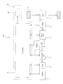
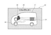
- FIG. 1 is a diagram showing a schematic configuration of a hybrid vehicle in which the energy flow display method according to the present embodiment is performed.
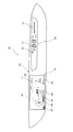
- FIG. 2 is a view showing an example of a display of a display system mounted on a hybrid vehicle.
- FIG. 3 is a schematic configuration diagram of a display system mounted on a hybrid vehicle.
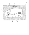
- FIG. 4 is a view showing a display state of the display when the hybrid vehicle is traveling by the electric motor in the engine stop state.
- FIG. 5 is a diagram showing a display state of the display when the hybrid vehicle is decelerating and traveling with the engine stopped and regenerative charging is performed by the electric motor.
- FIG. 6 is a diagram showing a display state of the display when the hybrid vehicle is traveling by the electric motor while charging the battery by power generation by the engine.
- FIG. 1 is a diagram showing a schematic configuration of a hybrid vehicle in which the energy flow display method according to the present embodiment is performed.
- FIG. 2 is a view showing an example of a display of a display system mounted
- FIG. 7 is a diagram showing the display state of the display when the hybrid vehicle is accelerating by driving the electric motor using both the power generated by the engine and the battery power.
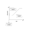
- FIG. 8 is a diagram showing an example of a vehicle speed-reference rotational speed map.
- FIG. 9 is a diagram showing a display state of the display when motoring control for driving the generator to drive the engine based on the battery power is executed.
- FIG. 10 is a view showing a display state of the display when the hood covering the engine room accommodating the engine and the electric motor is opened.
- FIG. 11 is a diagram showing a display state of a display of a display system according to a modification of the present embodiment.
- FIG. 1 is a diagram showing a schematic configuration of a hybrid vehicle 100 in which the energy flow display method according to the present embodiment is performed.
- a hybrid vehicle 100 includes an engine 1, a generator 2, a generator inverter 3, a battery 4, a motor inverter 5, an electric motor 6, a reduction gear 7, and drive wheels 8. , And a controller 10 that controls various devices.
- the hybrid vehicle 100 supplies power generated by the generator 2 to the battery 4 using the power of the engine 1 and drives the drive wheel 8 by rotating the electric motor 6 based on the power of the battery 4. It is configured as a hybrid vehicle. Therefore, in hybrid vehicle 100, engine 1 is not used as a motive power source for causing the vehicle to travel, but as a motive power source for generating electric power from generator 2.
- the engine 1 constituting the hybrid vehicle 100 is a so-called internal combustion engine that uses gasoline or the like as a fuel, and is mechanically connected to the generator 2 via a gear (not shown).
- the engine 1 is used as a drive source for rotationally driving the generator 2 when charging the battery 4 or the like.
- the generator 2 generates electricity by rotating based on the power from the engine 1 and is configured to be able to charge the battery 4.
- the generator 2 is also configured to cause the engine 1 to perform a powering operation (motoring) by being rotationally driven by the electric power of the battery 4.
- motoring control that rotates the engine 1 using the power of the generator 2, when cranking the engine 1 when the engine is started, the throttle valve is closed when a negative pressure for brake pedal assistance is required, and When generating pressure, it is performed when you want to consume power to prevent overcharging of the battery.
- the generator 2 functions as a so-called motor generator.
- the generator inverter 3 is electrically connected to the generator 2, the battery 4, and the motor inverter 5.
- the generator inverter 3 converts AC power generated by the generator 2 into DC power and supplies the DC power to the battery 4 and the motor inverter 5, converts DC power output from the battery 4 into AC power, and converts the AC power into the generator 2. It is configured to supply.
- the motor inverter 5 is electrically connected to the generator inverter 3, the battery 4, and the electric motor 6.
- the motor inverter 5 converts DC power output from the battery 4 and the generator inverter 3 into AC power and supplies the AC power to the motor 6, converts AC power regenerated by the motor 6 into DC power, and converts the DC power It is configured to supply four.
- the electric motor 6 is rotationally driven by the alternating current supplied from the motor inverter 5, and transmits the driving force to the drive wheel 8 via the reduction gear 7. Further, the electric motor 6 is configured to generate electric power when it is rotated by the drive wheel 8 and rotated at the time of vehicle deceleration, coast traveling, etc., and recover the kinetic energy of the vehicle to the battery 4 as electric energy. Thus, the electric motor 6 functions as a motor generator.
- the controller 10 is constituted by a microcomputer provided with a central processing unit (CPU), a read only memory (ROM), a random access memory (RAM) and an input / output interface (I / O interface).
- the controller 10 functions as a control unit that controls the operation of various devices such as the engine 1, the generator 2, the generator inverter 3, and the motor inverter 5 by executing a specific program.
- the controller 10 may be configured not by one microcomputer but by a plurality of microcomputers.
- the controller 10 controls the throttle valve, injector, spark plug, etc. of the engine 1 according to the rotational speed and load (torque) state signals of the engine 1 to adjust the intake air amount, fuel injection amount, ignition timing etc. Do.
- the controller 10 calculates the state of charge (SOC: State Of Charge) of the battery 4 based on the current and voltage at the time of charge and discharge of the battery 4 and uses the calculated SOC information etc. Calculate the available power.
- SOC State Of Charge
- the controller 10 issues a motor torque command to the electric motor 6 according to information such as accelerator opening, vehicle speed, vehicle state information such as road surface gradient, SOC information, inputtable power of the battery 4 and outputtable power of the battery 4 A value is calculated, or a target generated power to be supplied from the generator 2 to the battery 4 or the electric motor 6 is calculated. Further, the controller 10 performs switching control of the motor inverter 5 so that the torque of the electric motor 6 becomes a motor torque command value.
- the controller 10 calculates an engine torque command value for the engine 1 and a rotational speed command value for the generator 2 in order to realize the target generated power.
- the controller 10 performs switching control of the generator inverter 3 in accordance with the state of the rotational speed detection value of the generator 2 or the like so that the generator rotational speed matches the rotational speed command value.
- the hybrid vehicle 100 described above displays the energy flow indicating the flow of electric power between the engine 1 and the battery 4 and between the battery 4 and the electric motor 6 for driving the drive wheel 8 to thereby operate the vehicle.
- a display system 60 for causing a driver or the like to recognize.
- the display system 60 includes a display 50 disposed in the vehicle compartment of the hybrid vehicle 100, and a controller 10 that executes control related to image display of the display 50. It should be noted that the energy flow display between the battery 4 and the electric motor 6 may be omitted and the driver may recognize only the power generation state by the engine 1.
- FIG. 2 is a view showing an example of a display screen of the display unit 50 of the display system 60. As shown in FIG.
- Display 50 shown in FIG. 2 is configured of a display incorporated in an instrument panel disposed in front of a cabin of hybrid vehicle 100.
- the display function of the display 50 can be realized by various image display devices such as a liquid crystal display, an organic EL, and an LED.
- the display 50 is configured to perform display based on a display control signal from the controller 10.
- the display 50 has a first display area 30 located closer to the right in FIG. 2 and a second display area 40 located closer to the left in FIG.
- the first display area 30 has a vehicle speed display unit 31 that displays the current vehicle speed of the hybrid vehicle 100, and a direction indication display unit 32 that is displayed when the hybrid vehicle 100 turns right or left. Further, on the right side of the first display area 30, an eco level gauge 33 indicating the eco driving degree of the hybrid vehicle 100 is displayed.
- the eco level is an index that indicates in stages how good the current driving condition of the hybrid vehicle 100 is (the energy consumption efficiency).
- the display is made to expand and contract the eco level gauge 33 in accordance with the level of the eco level according to the motor output, thereby providing the driver with an index of what extent the current eco driving degree is. be able to.
- the second display area 40 includes a vehicle state display unit 20, a time display unit 41 for displaying the current time, and a travel mode display unit 42 for displaying the currently set travel mode and the range position of the shift lever. Have. Furthermore, in the second display area 40, a trip information display unit 43 indicating a travel distance during one trip and a travelable distance indicating a travelable distance based on the remaining amount of fuel stored in the fuel tank for power generation of the engine 1 Display portion 44, Fuel remaining amount display portion 45 indicating the remaining amount of fuel in the fuel tank, Filler port position display portion 46 for displaying the position (right side position or left side position) where the fuel supply port is installed, Battery 4 And a charge amount display unit 47 for displaying a charge amount (SOC) of
- the vehicle state display unit 20 in the second display area 40 can selectively display a predetermined vehicle state display among a plurality of types of vehicle state displays by an operation of a driver or the like.
- a predetermined vehicle state display for displaying an energy flow between the engine 1 and the battery 4 and between the battery 4 and the drive wheel 8, and a power meter for displaying a drive output amount and a regeneration amount by the electric motor 6.
- a display, a charge history information display indicating a history of charge amount by charging using the engine 1 or regenerative charging using the electric motor 6 and the like are included. In the present embodiment, a case where energy flow display is displayed on the vehicle state display unit 20 will be described.
- the controller 10 that constitutes a part of the display system 60 is electrically connected to various sensors that detect the driving state of the hybrid vehicle 100.
- the various sensors include voltage sensor 11, current sensor 12, crank angle sensor 13, motor rotation angle sensor 14, ignition switch 15, accelerator pedal sensor 16, brake pedal sensor 17, position sensor 18, hood open / close sensor 19 and the like. Be These sensors are an example of sensors that detect the driving state of the vehicle, and it is not excluded that the controller 10 is connected to other sensors.
- the voltage sensor 11 and the current sensor 12 are provided in the battery 4 and detect the battery voltage and the battery current at the time of charge and discharge.
- the crank angle sensor 13 is provided in the engine 1 and detects the rotational position of the crankshaft of the engine 1.
- the motor rotation angle sensor 14 is provided to the electric motor 6 and detects the rotational position of the rotor of the electric motor 6.
- the controller 10 calculates the engine rotation speed based on the detection signal of the crank angle sensor 13 and calculates the motor rotation speed based on the detection signal of the motor rotation angle sensor 14.
- the ignition switch 15 is a power switch operated by a driver or the like to enable the hybrid vehicle 100 to run.
- the accelerator pedal sensor 16 is a sensor that detects the amount of depression of the accelerator pedal provided in the hybrid vehicle 100
- the brake pedal sensor 17 is a sensor that detects the amount of depression of the brake pedal provided in the hybrid vehicle 100.
- the depression amount of the accelerator pedal is vehicle state information that represents the load on the electric motor 6, and the depression amount of the brake pedal is vehicle state information that represents the braking amount.
- the position sensor 18 is a sensor that detects the range position of the shift lever provided in the hybrid vehicle 100.
- the range position of the shift lever includes a parking range (P range), a neutral range (N range), a forward travel range (D range), a reverse travel range (R range), and the like.
- the hood open / close sensor 19 is a sensor for detecting the open / close state of a hood (bonnet) covering an engine room (housing room) accommodating the engine 1 and the electric motor 6 provided in front of the hybrid vehicle 100 or the like.
- the controller 10 performs energy flow information indicating the power supply state between the engine 1 and the battery 4 and the power supply state between the battery 4 and the electric motor 6 based on detection signals from the various sensors described above. While calculating, the display command signal for controlling the display 50 is calculated based on energy flow information etc. Various information related to the energy flow is displayed on the vehicle state display unit 20 (see FIG. 2) of the display 50 based on the display command signal from the controller 10.
- the energy flow information includes the power generated by the generator 2, the drive power supplied to the electric motor 6, the regenerated power by the electric motor 6, and the like.
- the energy flow display on the vehicle state display unit 20 of the display unit 50 in various driving states of the hybrid vehicle 100 will be described with reference to FIGS. 4 to 7.
- a series of energy flow display described below is realized by the controller 10 executing a predetermined program to control the display 50.
- FIG. 4 is a view showing a display state of the vehicle state display unit 20 when the hybrid vehicle 100 is traveling by the electric motor 6 in a state where the engine 1 is stopped.
- the hybrid vehicle 100 is displayed on the vehicle state display unit 20 as a basic display of energy flow display.
- a vehicle icon 21 shown, an engine icon 22 showing the engine 1, a battery icon 23 showing the battery 4, and a drive wheel icon 24 showing the drive wheel 8 are displayed.
- a flow icon 25 indicating an energy flow according to the vehicle operation state is displayed between the engine icon 22 and the battery icon 23, and between the battery icon 23 and the drive wheel icon 24. .
- the engine icon 22 is an icon resembling an engine shape, and is displayed superimposed on the front of the vehicle icon 21.
- the color (display mode) displayed on the vehicle state display unit 20 of the engine icon 22 is changed according to the engine rotational speed calculated based on the detection signal of the crank angle sensor 13.
- the battery icon 23 is an icon imitating a battery shape for imaging a battery, and is displayed superimposed on the rear of the vehicle icon 21.
- the battery icon 23 displays the battery charge amount according to the SOC calculation value calculated based on the detection signals of the voltage sensor 11 and the current sensor 12.
- the battery icon 23 is configured to be able to recognize the current battery charge amount by bar graph display inside the icon, and the bar graph display is displayed longer as the SOC calculation value is larger.
- the bar graph of the battery icon 23 is displayed in blue when the calculated SOC is larger than the charge lower limit, and is displayed in yellow when the calculated SOC is less than the charge lower limit.
- the driving wheel icon 24 imitates the shape of the front wheel of the vehicle, and is displayed as an icon (vehicle driving unit icon) which constitutes a part of the vehicle icon 21.
- the rotation state of the drive wheel icon 24 displayed on the vehicle state display unit 20 is changed according to the motor rotation speed calculated based on the detection signal of the motor rotation angle sensor 14.
- the drive wheel icon 24 is configured to be displayed in a higher rotation as the motor rotation speed increases.
- the flow icon 25 is displayed as an arrow-like icon indicating the direction of power supply between the engine 1 and the battery 4 and the direction of power supply between the battery 4 and the drive wheel 8.
- Flow icon 25 is a flow icon 25A (see FIG. 6) displayed between engine icon 22 and battery icon 23, and a flow icon 25B displayed between battery icon 23 and driving wheel icon 24 (see FIG. 4) And contains.
- the power of the battery 4 is not directly supplied to the drive wheel 8, but since there is a certain relationship between the drive state of the drive wheel 8 and the drive state of the electric motor 6, the battery The direction of power supply between the electric motor 6 and the electric motor 6 is displayed as an energy flow between the battery icon 23 and the drive wheel icon 24 on the energy flow display.
- the controller 10 is configured to control the display mode and the like of the various icons 21, 22, 23, 24, 25A, 25B. That is, the controller 10 controls the display mode and the like of the engine icon 22 according to the engine rotation state (engine rotational speed) and the flow display control unit that controls the display mode and the like of the flow icons 25A and 25B according to the vehicle traveling state.
- a drive display control unit that controls the These display control units may be configured to be included in different controllers.
- the display 50 is controlled to display the engine icon 22 in gray (the first display mode) based on the fact that the engine rotational speed is zero.
- the controller 10 controls the flow icon 25A between the engine icon 22 and the battery icon 23 in the vehicle state display unit 20 to be hidden.
- the controller 10 drives the electric wheel 6 using the electric power of the battery 4 to drive the driving wheel 8, so the controller 10 flows a flow icon 25 B between the battery icon 23 and the driving wheel icon 24. Is controlled to display in blue. In this case, in order to indicate that the drive wheel 8 is driven based on the power of the battery 4, the flow icon 25B is displayed such that the tip of the arrow is directed in the direction from the battery icon 23 toward the drive wheel icon 24. Ru.
- the engine icon 22 is displayed in gray (the first display mode) in the vehicle state display unit 20 of the display 50, and the vehicle icon is traveled from the battery icon 23 toward the driving wheel icon 24 A flow icon 25B indicating that necessary energy (power) is supplied is displayed in blue.
- the flow icon 25B in the non-charging travel state is configured to be changed in thickness in accordance with the magnitude of the power supplied from the battery 4 to the electric motor 6. Therefore, the controller 10 controls the display unit 50 to display the flow icon 25B thicker, for example, when the supply power is larger than the reference supply power.
- the controller 10 may be configured to control the display 50 such that the thickness of the flow icon 25B gradually increases as the supplied power increases.
- the controller 10 displays the engine icon 22 in gray (the first display mode) based on the fact that the engine rotational speed is zero, and between the engine icon 22 and the battery icon 23 Control to hide the flow icon 25A.
- the controller 10 has a battery icon
- the display 50 is controlled to display the flow icon 25 B in blue between the wheel 23 and the drive wheel icon 24.
- the flow icon 25B is an arrow in a direction from the drive wheel icon 24 to the battery icon 23. Displayed so that the tip is facing.
- the controller 10 displays a charging icon imitating the shape of a lightning bolt in the battery icon 23 in order to make it easier to grasp that the battery 4 is being charged.
- the engine icon 22 is displayed in gray (the first display mode) in the vehicle state display unit 20 of the display 50, and the driving wheel icon 24 to the battery icon 23
- a flow icon 25B indicating that energy (electric power) by regenerative charging is supplied is displayed in blue.
- the flow icon 25B is also set to the same display mode (blue) as in the case where the drive wheel 8 is driven by the electric motor 6, even when the regenerative charging is performed by the electric motor 6.
- the flow icon 25B is configured such that the thickness is changed in accordance with the magnitude of the regenerative power charged from the electric motor 6 to the battery 4. Therefore, for example, when the regenerative power is larger than the reference regenerative power, the controller 10 controls the display 50 to display the flow icon 25B thicker than when the regenerative power is smaller.
- the value of the reference regenerative power serving as a reference for adjusting the thickness of the flow icon 25B during regenerative charging is greater than the value of the reference supply power serving as a reference for adjusting the thickness of the flow icon 25B during non-charging travel. It is set large.
- the controller 10 may be configured to control the display 50 so that the thickness of the flow icon 25B gradually increases as the regenerative power increases.
- a display state of the vehicle state display unit 20 when the hybrid vehicle 100 is traveling by the electric motor 6 while charging the battery 4 by power generation by the engine 1 will be described with reference to FIG.
- the power of the engine 1 is used to drive the generator 2, and the power generated by the generator 2 is stored in the battery Charge to 4.
- the engine 1 is controlled to operate at an operating point with high fuel efficiency according to the vehicle traveling state.
- the controller 10 calculates the engine rotation speed based on the detection signal of the crank angle sensor 13, and determines whether the calculated engine rotation speed is equal to or less than the reference rotation speed.
- the controller 10 is controlled so that the engine 1 is controlled in a state of good fuel efficiency, etc.
- the icon 22 is displayed in green (second display mode).
- the reference rotational speed is determined in advance by experiments and evaluations, and is set to a rotational speed at which a general driver feels that the engine noise is large. For example, the reference rotational speed is set to 2500 rpm.
- the controller 10 controls the display 50 to display the flow icon 25A in yellow between the engine icon 22 and the battery icon 23 Do.
- the flow icon 25A is displayed such that the tip of the arrow points in the direction from the engine icon 22 to the battery icon 23.
- the controller 10 displays a charging icon imitating the shape of a lightning bolt in the battery icon 23 in order to make it easier to grasp that the battery 4 is being charged.
- the flow icon 25A in the normal driving state at the time of charging is configured to be changed in thickness in accordance with the magnitude of the power supplied from the generator 2 driven by the engine 1 to the battery 4. Therefore, for example, when the charging power is larger than the reference charging power, the controller 10 controls the display 50 to display the flow icon 25A thicker than when the charging power is smaller.
- the value of the reference charging power serving as a reference for adjusting the thickness of the flow icon 25A during charging using the engine 1 is larger than the value of the reference regenerative power serving as a reference for adjusting the thickness of the flow icon 25B during regenerative charging travel. It is set.
- the controller 10 may be configured to control the display 50 such that the thickness of the flow icon 25A gradually increases as the charging power increases.
- the controller 10 since the electric motor 6 is rotationally driven using the electric power of the battery 4 and the driving wheel 8 is driven by the power of the electric motor 6 in the normal driving state during charging, the controller 10 includes the battery icon 23 and the driving wheel icon The display 50 is controlled to display the flow icon 25B in blue between the position 24 and the position 24.
- the display control of the flow icon 25B at this time is the same control as the case of the non-charging traveling state described in FIG.
- the engine icon 22 is displayed in green (second display mode) in the vehicle state display unit 20 of the display unit 50. Furthermore, a flow icon 25A indicating that charging energy is being supplied from the engine icon 22 toward the battery icon 23 is displayed in yellow on the vehicle state display unit 20, and the battery icon 23 to the driving wheel icon 24. A flow icon 25B indicating that energy necessary for traveling the vehicle is supplied is displayed in blue.
- the display state of the vehicle state display unit 20 when the hybrid vehicle 100 is accelerated by driving the electric motor 6 using both of the power generated by the engine 1 and the battery power will be described.
- the power supplied to the electric motor 6 may be insufficient with battery power alone.
- the battery power is supplemented by the power generated by the engine 1, and the desired power is supplied to the electric motor 6.
- priority is given to generated power over fuel consumption, and the engine 1 is controlled at high rotation speed and high load than that during normal traveling. Therefore, in the acceleration traveling state, the rotational speed of the engine 1 is increased to increase the power generated by the generator 2 while sacrificing the fuel efficiency of the engine 1 to some extent.
- the controller 10 calculates the engine rotation speed based on the detection signal of the crank angle sensor 13, and determines whether the calculated engine rotation speed is equal to or less than the reference rotation speed.
- the controller 10 is controlled in an inefficient operating state such as when the engine 1 is controlled at a high rotational speed, and not recommended from the viewpoint of eco-driving
- the engine icon 22 is displayed in yellow (third display mode) so that the user can visually recognize that it is.
- the controller 10 displays the flow icon 25A in yellow between the engine icon 22 and the battery icon 23, and the battery icon
- the display 50 is controlled to display the flow icon 25 B in blue between the wheel 23 and the drive wheel icon 24.
- the flow icon 25A is displayed so that the tip of the arrow is directed in the direction from the engine icon 22 toward the battery icon 23, and the flow icon 25B is such that the tip of the arrow is directed in the direction from the battery icon 23 toward the drive wheel icon 24 Is displayed on.
- the power generated by the engine 1 may be larger than the above-described reference charging power, and the power supplied to the electric motor 6 may also be larger than the reference power.
- the flow icons 25A and 25B are displayed in a thick display mode as shown in FIG.
- the engine icon 22 is displayed in yellow (third display mode) in the vehicle state display unit 20 of the display unit 50. Furthermore, a flow icon 25A indicating that charging energy is being supplied from the engine icon 22 toward the battery icon 23 is displayed in yellow on the vehicle state display unit 20, and the battery icon 23 to the driving wheel icon 24. A flow icon 25B indicating that energy necessary for traveling the vehicle is supplied is displayed in blue.
- the display system 60 display method of the hybrid vehicle 100 according to the present embodiment
- the engine when displaying the energy flow based on the vehicle driving state, the engine according to the engine rotational speed
- the color (display mode) of the icon 22 is changed.
- the color (display mode) of the engine icon 22 is determined by comparing the calculated value of the engine rotational speed with the reference rotational speed.
- the reference rotational speed may be a predetermined constant value, or as shown in FIG. 8, the value of the reference rotational speed may be determined based on the vehicle speed calculated from the motor rotational speed.
- the vehicle speed-reference rotational speed map is set to, for example, a low reference rotational speed in the low speed region and a high reference rotational speed in the high speed region. In the middle speed range, the reference rotation speed is set to be higher as the vehicle speed becomes higher between the low reference rotation speed and the high reference rotation speed.
- the controller 10 is configured to control the display 50 so as to display the engine icon 22 in yellow when the calculated value of the engine rotational speed is larger than the reference rotational speed according to the current vehicle speed.
- the vehicle speed-reference rotational speed map shown in FIG. 8 is an example, and the map may be a map in which the reference rotational speed is directly proportional to the vehicle speed such that the reference rotational speed increases as the vehicle speed increases.
- controller 10 is configured to calculate the vehicle speed based on the detection signal of the motor rotation angle sensor 14, the controller 10 is configured to calculate the vehicle speed based on the detection signal of the vehicle speed sensor provided in the hybrid vehicle It is also good.
- FIG. 9 is a diagram showing a display state of the vehicle state display unit 20 when motoring control for operating the generator 2 to drive the engine 1 based on battery power is executed.
- the motoring control is performed, for example, in a situation where negative pressure generation for brake pedal assist is required.
- a negative pressure for assisting the brake pedal is generated in the intake passage of the engine 1 by driving the engine 1 with the generator 2 in a state where the intake passage of the engine 1 is closed by the slot valve. Be done.
- the motoring control is performed not only when generating negative pressure, but also when cranking the engine 1 when starting the engine, or when the regenerative power from the electric motor 6 is not charged to the battery 4; It is also executed when it is consumed by.
- FIG. 9 exemplifies a time when motoring control is performed to generate a negative brake pressure when the hybrid vehicle 100 is traveling.
- the controller 10 controls the battery icon 23 and the driving wheel icon 24. And displays the flow icon 25B in blue and controls the display unit 50 to display the engine icon 22 in green (second display mode).
- the generator 2 is operated based on the power supplied from the battery 4 to drive the engine 1, but the controller 10 daresly displays the flow icon 25A from the battery icon 23 to the engine icon 22 It is configured not to. Therefore, as shown in FIG. 9, the flow icon 25A is hidden between the engine icon 22 and the battery icon 23.
- the controller 10 basically changes the color of the engine icon 22 according to the engine rotation speed, but is configured to always display the engine icon 22 in green regardless of the engine rotation speed during motoring control.
- the motoring control is executed independently of the driver's accelerator operation, and the engine 1 starts operation at a timing not intended by the driver. Although the driver may hear the rotational operation noise of the engine 1 when it can not recognize that the engine 1 is motoring controlled, the driver may cause the driver to feel discomfort.
- the engine icon 22 is green (in the same manner as in the case where the engine rotational speed shown in FIG. In order to display in the second display mode, the driver can be made aware that the engine 1 is appropriately controlled. Therefore, even when the motoring control is executed regardless of the driver's intention, it is possible to avoid giving the driver a sense of discomfort.
- FIG. 10 is a view showing a display state of the vehicle state display unit 20 when the hood covering the engine room accommodating the engine 1 and the electric motor 6 is opened when the hybrid vehicle 100 is stopped.
- the controller 10 determines whether the vehicle is stopped based on the vehicle speed calculated from the motor rotation speed and the detection signal of the brake pedal sensor 17, and the hood is opened based on the detection signal of the hood open / close sensor 19. It is determined whether or not it is in the state. When the hood is in an open state when the vehicle is stopped, the controller 10 hides the display of the flow icons 25A and 25B and displays the engine icon 22 in yellow (third display mode) Control 50
- the controller 10 basically changes the color of the engine icon 22 according to the engine rotation speed, but is configured to always display the engine icon 22 in yellow regardless of the engine rotation speed when the hood is open There is. It is not recommended that the hood be opened while the engine 1 is in operation for safety reasons. Therefore, in the present embodiment, when the hood is opened, the engine icon 22 is yellow (the same as in the case where the engine rotational speed shown in FIG. 7 is controlled in a state larger than the reference rotational speed). (3) In the display mode, the driver can recognize that the engine 1 is placed in an environment not recommended from the viewpoint of eco-driving and the like.
- the controller 10 may be configured to display the engine icon 22 in yellow (third display mode) when the hood is open regardless of whether the vehicle is stopped.
- the controller 10 displays the engine icon 22 in yellow when the hood is in the open state, but the engine 1 is not recommended even when the accelerator pedal is depressed when the shift lever is in the P range.
- the display 50 may be controlled to display the engine icon 22 in yellow (third display mode) as being in operation. In this case, the controller 10 determines whether the shift lever is in the P range based on the detection signal of the position sensor 18, and determines whether the accelerator pedal is depressed based on the detection signal of the accelerator pedal sensor 16. Do.
- the controller 10 causes the engine icon 22 to be displayed in yellow when the engine 1 is not recommended from the viewpoint of eco-driving or the like, but in such a case, gray (first display mode) or The green (second display mode) and the yellow (third display mode) may be displayed in a different color (fourth display mode). For example, if red is adopted as the fourth display mode of the engine icon 22, it is possible to make the driver or the like strongly recognize that the engine 1 is not recommended from the viewpoint of eco-driving and the like.
- the display system 60 of the hybrid vehicle 100 is a system that displays the energy flow between at least the engine 1 and the battery 4.
- the display system 60 is a display that allows the driver to visibly display an engine icon 22 indicating the engine 1, a battery icon 23 indicating the battery 4, and a flow icon 25A indicating energy flow between the engine icon 22 and the battery icon 23.
- the controller 10 that controls the display of each icon according to the driving state of the hybrid vehicle 100.
- the controller 10 flow display control unit
- the controller 10 acquires the rotation state of the engine, and displays the engine icon 22 in the first display mode (for example, gray) when the engine 1 is stopped. Furthermore, the controller 10 causes the engine icon 22 to be displayed in a second display mode (for example, green) different from the first display mode when the engine 1 is operating with the engine rotational speed equal to or lower than the reference rotational speed. When the speed is higher than the reference rotation speed, the engine icon 22 is displayed in a third display mode (for example, yellow) different from the first and second display modes.
- a second display mode for example, green
- the display mode of the engine icon 22 is changed according to the engine rotational speed, so the rotational speed of the engine 1 It is possible to realize the associated energy flow display.
- the driver or the like can simultaneously grasp the flow of energy according to the vehicle operating state and in what state the engine 1 is controlled.
- the controller 10 of the display system 60 determines whether or not the motoring in which the engine 1 is driven by the generator 2 is performed, and in the second display mode (for example, green) when the motoring is performed.
- the engine icon 22 is displayed.
- the controller 10 engine rotation state display control unit
- the motoring control is performed by the driver in order to display the engine icon 22 in the second display mode as in the case where the engine rotational speed is controlled below the reference rotational speed. Even when executed regardless of the intention, it is possible to make the driver or the like recognize that the engine 1 is not being driven unnecessarily but appropriately controlled.
- the controller 10 (flow display control part) is a display mode (for example, non-display) which shows that there is no energy flow between the engine 1 and the battery 4, when the engine 1 is rotationally driven by the generator 2. Control to display the flow icon 25A.
- the motoring control is executed regardless of the driver's intention by controlling the display of the flow icon 25A in a display mode indicating that there is no energy flow. Even in this case, it is possible to prevent the driver from feeling uncomfortable.
- the controller 10 (engine rotation state display control unit) of the display system 60 determines whether or not the hood covering the engine room accommodating the engine 1 is open, and when the hood is open, the third display mode (for example, The engine icon 22 is displayed in yellow).
- the controller 10 determines whether the accelerator pedal is depressed with the shift lever in the parking position, and the accelerator pedal is depressed with the shift lever in the parking position. If the engine icon 22 is broken, the engine icon 22 is displayed in the third display mode. In such a case, the engine icon 22 is displayed in the third display mode in the same manner as in the case where the engine rotational speed is controlled to be larger than the reference rotational speed.
- the driver or the like can recognize that the state is not recommended.
- the fourth display mode (for example, red) different from the first to third display modes of the engine icon 22 when the hood is open and when the accelerator pedal is depressed with the shift lever in the parking position The same effect can be expected by displaying in).
- the controller 10 engine rotation state display control unit of the display system 60 acquires the vehicle speed of the hybrid vehicle 100, and increases the reference rotation speed serving as the control reference of the display mode of the engine icon 22 as the vehicle speed increases. Whether or not the engine 1 is appropriately controlled from the viewpoint of eco driving etc. changes according to the vehicle speed, but by adjusting the reference rotation speed according to the vehicle speed, engine icon display control according to the vehicle speed is realized. It becomes possible.
- controller 10 engine rotation state display control unit
- the controller 10 displays engine icons 22 of different colors according to the display modes (first to fourth display modes).
- the driver can intuitively and instantaneously recognize the operating state of the engine 1 even while driving.
- the drive wheel icon 24 is displayed on the vehicle state display unit 20 of the display 50.
- a motor icon 26 indicating the electric motor 6 for actually driving the drive wheel 8 is shown.
- the flow icons 25A, 25B, etc. may be displayed between the engine icon 22 and the battery icon 23 and between the battery icon 23 and the motor icon 26.
- the drive wheel icon 24 and the motor icon 26 function as a vehicle drive unit icon in which a drive target for driving a vehicle is imaged.
- the first display mode of the engine icon 22 is gray
- the second display mode is green
- the third display mode is yellow
- the fourth display mode is red
- the display mode of the engine icon 22 is not limited to the color, and may be the size of the engine icon 22, the rotation speed of a gear included in the engine icon 22, or the like, or a combination thereof.
- the size is adopted as the display mode, for example, the size of the engine icon 22 is adjusted to increase in the order of the first to fourth display modes.
- the rotation speed of the gear is adopted as the display mode, for example, the rotation of the gear included in the engine icon 22 is adjusted to be faster in the order of the first to fourth display modes.
Abstract
Description
Claims (14)
- エンジンの動力を用いてバッテリを充電可能な発電機と、前記バッテリの電力に基づいて駆動輪を駆動する電動モータとを備えるハイブリッド車両において、少なくとも前記エンジンと前記バッテリとの間のエネルギフローを表示する表示方法であって、
前記エンジンを示すエンジンアイコンと、前記バッテリを示すバッテリアイコンと、前記エンジンアイコンと前記バッテリアイコンの間において前記エネルギフローを示すフローアイコンとを、前記ハイブリッド車両の運転状態に応じて表示器に表示させ、
前記バッテリが充電されている場合には、前記エンジンと前記バッテリとの間において前記エネルギフローがあることを示す表示態様で前記フローアイコンを表示させ、
前記エンジンが停止している場合には、第1表示態様で前記エンジンアイコンを表示させ、
エンジン回転速度が基準回転速度以下で前記エンジンが作動している場合には、前記第1表示態様とは異なる第2表示態様で前記エンジンアイコンを表示させ、
エンジン回転速度が前記基準回転速度より大きい場合には、前記第1及び第2表示態様とは異なる第3表示態様で前記エンジンアイコンを表示させる、
表示方法。 - 請求項1に記載の表示方法であって、
前記エンジンが前記発電機によって回転駆動される場合には、前記第2表示態様で前記エンジンアイコンを表示させ、且つ、エンジン回転速度が前記基準回転速度より大きい場合であっても前記第2表示態様で表示させる、
表示方法。 - 請求項1又は2に記載の表示方法であって、
前記エンジンが前記発電機によって回転駆動される場合には、前記エンジンと前記バッテリとの間において前記エネルギフローがないことを示す表示態様で前記フローアイコンを表示させる、
表示方法。 - 請求項1から3のいずれか一つに記載の表示方法であって、
前記エンジンを収容するエンジンルームを覆うフードが開いているか否かを判定し、
前記フードが開いている場合には、前記第3表示態様又は前記第1から第3表示態様とは異なる第4表示態様で前記エンジンアイコンを表示させる、
表示方法。 - 請求項1から4のいずれか一つに記載の表示方法であって、
シフトレバーがパーキング位置にある状態でアクセルペダルが踏みこまれているか否かを判定し、
シフトレバーがパーキング位置にある状態でアクセルペダルが踏みこまれている場合には、前記第3表示態様又は前記第1から第3表示態様とは異なる第4表示態様で前記エンジンアイコンを表示させる、
表示方法。 - 請求項1から5のいずれか一つに記載の表示方法であって、
前記ハイブリッド車両の車速を取得し、
前記車速が高くなるほど前記基準回転速度を高くする、
表示方法。 - 請求項1から6のいずれか一つに記載の表示方法であって、
各表示態様に応じてそれぞれ異なる色の前記エンジンアイコンを表示させる、
表示方法。 - エンジンの動力を用いてバッテリを充電可能な発電機と、前記バッテリの電力に基づいて駆動輪を駆動する電動モータとを備えるハイブリッド車両において、少なくとも前記エンジンと前記バッテリとの間のエネルギフローを表示する表示システムであって、
前記エンジンを示すエンジンアイコンと、前記バッテリを示すバッテリアイコンと、前記エンジンアイコンと前記バッテリアイコンの間において前記エネルギフローを示すフローアイコンとをドライバが視認可能に表示する表示器と、
前記バッテリが充電されている場合に、前記エンジンと前記バッテリとの間において前記エネルギフローがあることを示す表示態様で前記フローアイコンを表示させるフロー表示制御部と、
前記エンジンの回転状態を取得し、前記エンジンが停止している場合には第1表示態様で前記エンジンアイコンを表示させ、エンジン回転速度が基準回転速度以下で前記エンジンが作動している場合には前記第1表示態様とは異なる第2表示態様で前記エンジンアイコンを表示させ、エンジン回転速度が前記基準回転速度より大きい場合には前記第1及び第2表示態様とは異なる第3表示態様で前記エンジンアイコンを表示させるエンジン回転状態表示制御部と、
を備える表示システム。 - 請求項8に記載のハイブリッド車両の表示システムであって、
前記エンジン回転状態表示制御部は、前記エンジンが前記発電機によって回転駆動される場合には、前記第2表示態様で前記エンジンアイコンを表示させ、且つ、エンジン回転速度が前記基準回転速度より大きい場合であっても前記第2表示態様で表示させる、
表示システム。 - 請求項8又は9に記載のハイブリッド車両の表示システムであって、
前記フロー表示制御部は、前記エンジンが前記発電機によって回転駆動される場合には、前記エンジンと前記バッテリとの間において前記エネルギフローがないことを示す表示態様で前記フローアイコンを表示させる、
表示システム。 - 請求項8から10のいずれか一つに記載のハイブリッド車両の表示システムであって、
前記エンジン回転状態表示制御部は、前記エンジンを収容するエンジンルームを覆うフードが開いているか否かを判定し、前記フードが開いている場合には前記第3表示態様又は前記第1から第3表示態様とは異なる第4表示態様で前記エンジンアイコンを表示させる、
表示システム。 - 請求項8から11のいずれか一つに記載のハイブリッド車両の表示システムであって、
前記エンジン回転状態表示制御部は、シフトレバーがパーキング位置にある状態でアクセルペダルが踏みこまれているか否かを判定し、シフトレバーがパーキング位置にある状態でアクセルペダルが踏みこまれている場合には前記第3表示態様又は前記第1から第3表示態様とは異なる第4表示態様で前記エンジンアイコンを表示させる、
表示システム。 - 請求項8から12のいずれか一つに記載のハイブリッド車両の表示システムであって、
前記エンジン回転状態表示制御部は、前記ハイブリッド車両の車速を取得し、前記車速が高くなるほど前記基準回転速度を高くする、
表示システム。 - 請求項8から13のいずれか一つに記載のハイブリッド車両の表示システムであって、
前記エンジン回転状態表示制御部は、各表示態様に応じてそれぞれ異なる色の前記エンジンアイコンを表示させる、
表示システム。
Priority Applications (9)
| Application Number | Priority Date | Filing Date | Title |
|---|---|---|---|
| CN201780097737.1A CN111479715B (zh) | 2017-12-15 | 2017-12-15 | 混合动力车辆中的显示方法和显示系统 |
| KR1020207017381A KR102356538B1 (ko) | 2017-12-15 | 2017-12-15 | 하이브리드 차량에 있어서의 표시 방법 및 표시 시스템 |
| EP17934452.8A EP3725575B1 (en) | 2017-12-15 | 2017-12-15 | Display method and display system in hybrid vehicle |
| BR112020011874-5A BR112020011874A2 (pt) | 2017-12-15 | 2017-12-15 | método de exibição e sistema de exibição para veículo híbrido |
| PCT/JP2017/045209 WO2019116575A1 (ja) | 2017-12-15 | 2017-12-15 | ハイブリッド車両における表示方法及び表示システム |
| JP2019558864A JP6897794B2 (ja) | 2017-12-15 | 2017-12-15 | ハイブリッド車両における表示方法及び表示システム |
| MX2020006124A MX2020006124A (es) | 2017-12-15 | 2017-12-15 | Metodo de despliegue y sistema de despliegue para vehiculo hibrido. |
| US16/771,985 US11465500B2 (en) | 2017-12-15 | 2017-12-15 | Display method and display system for hybrid vehicle |
| RU2020121795A RU2749927C1 (ru) | 2017-12-15 | 2017-12-15 | Способ отображения и система отображения для гибридного транспортного средства |
Applications Claiming Priority (1)
| Application Number | Priority Date | Filing Date | Title |
|---|---|---|---|
| PCT/JP2017/045209 WO2019116575A1 (ja) | 2017-12-15 | 2017-12-15 | ハイブリッド車両における表示方法及び表示システム |
Publications (1)
| Publication Number | Publication Date |
|---|---|
| WO2019116575A1 true WO2019116575A1 (ja) | 2019-06-20 |
Family
ID=66820135
Family Applications (1)
| Application Number | Title | Priority Date | Filing Date |
|---|---|---|---|
| PCT/JP2017/045209 WO2019116575A1 (ja) | 2017-12-15 | 2017-12-15 | ハイブリッド車両における表示方法及び表示システム |
Country Status (9)
| Country | Link |
|---|---|
| US (1) | US11465500B2 (ja) |
| EP (1) | EP3725575B1 (ja) |
| JP (1) | JP6897794B2 (ja) |
| KR (1) | KR102356538B1 (ja) |
| CN (1) | CN111479715B (ja) |
| BR (1) | BR112020011874A2 (ja) |
| MX (1) | MX2020006124A (ja) |
| RU (1) | RU2749927C1 (ja) |
| WO (1) | WO2019116575A1 (ja) |
Cited By (1)
| Publication number | Priority date | Publication date | Assignee | Title |
|---|---|---|---|---|
| JPWO2021019618A1 (ja) * | 2019-07-26 | 2021-02-04 |
Families Citing this family (6)
| Publication number | Priority date | Publication date | Assignee | Title |
|---|---|---|---|---|
| JP6745316B2 (ja) * | 2018-09-28 | 2020-08-26 | 本田技研工業株式会社 | 車両用情報表示装置 |
| JP2021038943A (ja) * | 2019-08-30 | 2021-03-11 | トヨタ自動車株式会社 | 表示システムおよびそれを備えた車両、ならびに、二次電池の状態表示方法 |
| USD944292S1 (en) * | 2019-09-02 | 2022-02-22 | Koninklijke Philips N.V. | Display screen or portion thereof with animated graphical user interface |
| JP7085580B2 (ja) * | 2020-03-30 | 2022-06-16 | 本田技研工業株式会社 | 制御装置、移動体、及び、プログラム |
| CN111707946B (zh) * | 2020-08-10 | 2023-04-14 | 广东爱德曼氢能源装备有限公司 | 燃料发电配套用锂电池检测方法及系统 |
| RU2764612C1 (ru) * | 2021-04-01 | 2022-01-18 | Владимир Григорьевич Гимпельсон | Привод гибридного автомобиля |
Citations (6)
| Publication number | Priority date | Publication date | Assignee | Title |
|---|---|---|---|---|
| JPH11159380A (ja) * | 1997-11-28 | 1999-06-15 | Suzuki Motor Corp | 車両用エンジンのオーバーヒート防止装置 |
| JP2007050889A (ja) | 2006-10-12 | 2007-03-01 | Toyota Motor Corp | ハイブリッド車の運転状態表示装置 |
| JP2008074326A (ja) * | 2006-09-25 | 2008-04-03 | Mazda Motor Corp | 車両用インスツルメントパネルの照明制御装置 |
| JP2009137553A (ja) * | 2007-12-11 | 2009-06-25 | Fujitsu Ten Ltd | 制御装置及び制御方法 |
| JP2015055163A (ja) * | 2013-09-10 | 2015-03-23 | トヨタ自動車株式会社 | 車両 |
| JP2016078662A (ja) * | 2014-10-17 | 2016-05-16 | 三菱自動車工業株式会社 | 電気自動車 |
Family Cites Families (23)
| Publication number | Priority date | Publication date | Assignee | Title |
|---|---|---|---|---|
| JP3018958B2 (ja) * | 1995-10-03 | 2000-03-13 | 三菱自動車工業株式会社 | ハイブリッド電気自動車における走行表示装置 |
| JP3092494B2 (ja) * | 1995-10-03 | 2000-09-25 | 三菱自動車工業株式会社 | 電気自動車の運転状態表示装置 |
| JP2921661B2 (ja) * | 1995-10-06 | 1999-07-19 | 株式会社エクォス・リサーチ | ハイブリッド車両 |
| JP3864403B2 (ja) * | 1998-01-30 | 2006-12-27 | マツダ株式会社 | ハイブリッド電気自動車における走行表示装置 |
| JP2000247164A (ja) * | 1999-02-26 | 2000-09-12 | Nissan Motor Co Ltd | ハイブリッド車両の表示装置 |
| JP2006290182A (ja) * | 2005-04-12 | 2006-10-26 | Nissan Motor Co Ltd | ハイブリッド車両の運転状態表示装置 |
| JP2008056058A (ja) * | 2006-08-30 | 2008-03-13 | Mitsubishi Heavy Ind Ltd | 荷役車両の表示装置及びこの表示装置を備えたハイブリッド式荷役車両 |
| JP2010011525A (ja) * | 2008-06-24 | 2010-01-14 | Toyota Motor Corp | 電動車両 |
| US20100057280A1 (en) * | 2008-08-29 | 2010-03-04 | Paccar Inc | Information display systems and methods for hybrid vehicles |
| US20100057281A1 (en) * | 2008-08-29 | 2010-03-04 | Paccar Inc | Information display systems and methods for hybrid vehicles |
| US8386104B2 (en) * | 2009-06-01 | 2013-02-26 | Ford Global Technologies, Llc | System and method for displaying power flow in a hybrid vehicle |
| KR20110083331A (ko) * | 2010-01-14 | 2011-07-20 | 현대모비스 주식회사 | 하이브리드 차량의 에너지 흐름 상태 정보 표시 장치 |
| US9613473B2 (en) * | 2011-01-06 | 2017-04-04 | Ford Global Technologies, Llc | Method and apparatus for energy usage display |
| KR101819941B1 (ko) * | 2011-01-27 | 2018-01-18 | 현대모비스 주식회사 | 에너지 흐름 표시 장치 |
| JP2012192800A (ja) * | 2011-03-15 | 2012-10-11 | Yupiteru Corp | 車両情報表示システム及びプログラム |
| KR20130036948A (ko) | 2011-10-05 | 2013-04-15 | 현대자동차주식회사 | 하이브리드 차량의 경제운전 유도 장치 및 그 방법 |
| US9292178B2 (en) * | 2012-03-09 | 2016-03-22 | Mitsubishi Jidosha Kogyo Kabushiki Kaisha | Information display apparatus for a vehicle |
| KR20130119771A (ko) * | 2012-04-24 | 2013-11-01 | 현대모비스 주식회사 | 하이브리드 차량에서 동력 흐름을 표시 방법 및 이를 표시하는 장치 |
| EP2896543B1 (en) * | 2012-09-11 | 2021-10-20 | Honda Motor Co., Ltd. | Hybrid vehicle |
| FR3013643B1 (fr) * | 2013-11-27 | 2017-03-03 | Technoboost | Dispositif d'affichage pour vehicule hybride qui comprend un moteur a combustion interne et au moins une source de puissance motrice d'hybridation |
| JP6471453B2 (ja) * | 2014-10-22 | 2019-02-20 | 株式会社デンソー | 車両用情報表示装置 |
| DE102014018138A1 (de) * | 2014-12-06 | 2016-06-09 | Daimler Ag | Verfahren zum Bereitstellen einer Anzeige auf einer Anzeigeeinrichtung eines Elektro- oder Hybridfahrzeugs und Elektro- oder Hybridfahrzeug |
| CN104908593A (zh) * | 2015-05-24 | 2015-09-16 | 湖北汽车工业学院 | 一种基于can的混合动力汽车lcd仪表装置 |
-
2017
- 2017-12-15 EP EP17934452.8A patent/EP3725575B1/en active Active
- 2017-12-15 RU RU2020121795A patent/RU2749927C1/ru active
- 2017-12-15 KR KR1020207017381A patent/KR102356538B1/ko active IP Right Grant
- 2017-12-15 US US16/771,985 patent/US11465500B2/en active Active
- 2017-12-15 CN CN201780097737.1A patent/CN111479715B/zh active Active
- 2017-12-15 WO PCT/JP2017/045209 patent/WO2019116575A1/ja unknown
- 2017-12-15 MX MX2020006124A patent/MX2020006124A/es unknown
- 2017-12-15 JP JP2019558864A patent/JP6897794B2/ja active Active
- 2017-12-15 BR BR112020011874-5A patent/BR112020011874A2/pt unknown
Patent Citations (6)
| Publication number | Priority date | Publication date | Assignee | Title |
|---|---|---|---|---|
| JPH11159380A (ja) * | 1997-11-28 | 1999-06-15 | Suzuki Motor Corp | 車両用エンジンのオーバーヒート防止装置 |
| JP2008074326A (ja) * | 2006-09-25 | 2008-04-03 | Mazda Motor Corp | 車両用インスツルメントパネルの照明制御装置 |
| JP2007050889A (ja) | 2006-10-12 | 2007-03-01 | Toyota Motor Corp | ハイブリッド車の運転状態表示装置 |
| JP2009137553A (ja) * | 2007-12-11 | 2009-06-25 | Fujitsu Ten Ltd | 制御装置及び制御方法 |
| JP2015055163A (ja) * | 2013-09-10 | 2015-03-23 | トヨタ自動車株式会社 | 車両 |
| JP2016078662A (ja) * | 2014-10-17 | 2016-05-16 | 三菱自動車工業株式会社 | 電気自動車 |
Non-Patent Citations (1)
| Title |
|---|
| See also references of EP3725575A4 |
Cited By (3)
| Publication number | Priority date | Publication date | Assignee | Title |
|---|---|---|---|---|
| JPWO2021019618A1 (ja) * | 2019-07-26 | 2021-02-04 | ||
| CN114174136A (zh) * | 2019-07-26 | 2022-03-11 | 日产自动车株式会社 | 混合动力车辆的控制方法以及混合动力车辆的控制装置 |
| JP7251632B2 (ja) | 2019-07-26 | 2023-04-04 | 日産自動車株式会社 | ハイブリッド車両の制御方法及びハイブリッド車両の制御装置 |
Also Published As
| Publication number | Publication date |
|---|---|
| KR20200087827A (ko) | 2020-07-21 |
| MX2020006124A (es) | 2020-08-24 |
| BR112020011874A2 (pt) | 2020-11-24 |
| EP3725575B1 (en) | 2021-08-25 |
| KR102356538B1 (ko) | 2022-02-09 |
| RU2749927C1 (ru) | 2021-06-21 |
| US11465500B2 (en) | 2022-10-11 |
| JP6897794B2 (ja) | 2021-07-07 |
| EP3725575A4 (en) | 2020-12-30 |
| US20200398666A1 (en) | 2020-12-24 |
| CN111479715B (zh) | 2023-06-27 |
| CN111479715A (zh) | 2020-07-31 |
| JPWO2019116575A1 (ja) | 2021-01-14 |
| EP3725575A1 (en) | 2020-10-21 |
Similar Documents
| Publication | Publication Date | Title |
|---|---|---|
| JP6897794B2 (ja) | ハイブリッド車両における表示方法及び表示システム | |
| JP5316466B2 (ja) | 表示装置 | |
| US9074683B2 (en) | Gear shift indication device | |
| JP5848828B2 (ja) | 内燃機関制御システム | |
| JP2994590B2 (ja) | ハイブリッド車両の制御装置 | |
| JP4240713B2 (ja) | 車両の制御装置 | |
| US20100029442A1 (en) | Braking/driving force control device | |
| JP5037669B2 (ja) | 出力制限制御装置、ハイブリッド自動車および出力制限制御方法、並びにプログラム | |
| KR20140073981A (ko) | 자동차의 구동 토크 제어 방법 및 시스템 | |
| US20190047589A1 (en) | Display device | |
| JP2010193602A (ja) | バッテリ温度制御装置、バッテリ温度制御方法及び自動車 | |
| JPH0998501A (ja) | 電気自動車の運転状態表示装置 | |
| BR112020011927A2 (pt) | método de controle para veículo híbrido e aparelho de controle para veículo híbrido | |
| JP5983469B2 (ja) | ハイブリッド車の制御装置 | |
| US11584353B2 (en) | Hybrid vehicle control method and hybrid vehicle control device | |
| JP2010173361A (ja) | ハイブリッド自動車 | |
| JP4483988B2 (ja) | 車両の制御装置 | |
| JP6923001B2 (ja) | 燃費表示制御方法及び燃費表示制御システム | |
| JP2020153292A (ja) | 車両制御システム、車両制御方法 | |
| JP7437364B2 (ja) | 表示制御装置 | |
| JP2024008640A (ja) | 表示制御装置 | |
| KR101755515B1 (ko) | 하이브리드 차량용 엔진 제어 장치 및 방법 | |
| JP2004301128A (ja) | ハイブリッド電気自動車のエンジン作動制御装置 | |
| JP2020059378A (ja) | ハイブリッド車両の制御システム | |
| JP2007202264A (ja) | 車両およびその制御方法 |
Legal Events
| Date | Code | Title | Description |
|---|---|---|---|
| 121 | Ep: the epo has been informed by wipo that ep was designated in this application |
Ref document number: 17934452 Country of ref document: EP Kind code of ref document: A1 |
|
| ENP | Entry into the national phase |
Ref document number: 2019558864 Country of ref document: JP Kind code of ref document: A |
|
| NENP | Non-entry into the national phase |
Ref country code: DE |
|
| ENP | Entry into the national phase |
Ref document number: 20207017381 Country of ref document: KR Kind code of ref document: A |
|
| ENP | Entry into the national phase |
Ref document number: 2017934452 Country of ref document: EP Effective date: 20200715 |
|
| REG | Reference to national code |
Ref country code: BR Ref legal event code: B01A Ref document number: 112020011874 Country of ref document: BR |
|
| ENP | Entry into the national phase |
Ref document number: 112020011874 Country of ref document: BR Kind code of ref document: A2 Effective date: 20200612 |