WO2019069425A1 - Dispositif de commande de véhicule, procédé de commande de véhicule et programme - Google Patents
Dispositif de commande de véhicule, procédé de commande de véhicule et programme Download PDFInfo
- Publication number
- WO2019069425A1 WO2019069425A1 PCT/JP2017/036282 JP2017036282W WO2019069425A1 WO 2019069425 A1 WO2019069425 A1 WO 2019069425A1 JP 2017036282 W JP2017036282 W JP 2017036282W WO 2019069425 A1 WO2019069425 A1 WO 2019069425A1
- Authority
- WO
- WIPO (PCT)
- Prior art keywords
- pedestrian
- vehicle
- road
- width
- recognition unit
- Prior art date
Links
- 238000000034 method Methods 0.000 title claims description 25
- 230000001133 acceleration Effects 0.000 claims abstract description 12
- 230000008569 process Effects 0.000 description 17
- 230000006870 function Effects 0.000 description 15
- 238000012545 processing Methods 0.000 description 13
- 238000004891 communication Methods 0.000 description 12
- 238000010586 diagram Methods 0.000 description 11
- 230000009471 action Effects 0.000 description 10
- 206010017577 Gait disturbance Diseases 0.000 description 9
- 210000003128 head Anatomy 0.000 description 6
- 230000006399 behavior Effects 0.000 description 4
- 230000008859 change Effects 0.000 description 4
- 238000001514 detection method Methods 0.000 description 4
- 238000002485 combustion reaction Methods 0.000 description 3
- 230000005484 gravity Effects 0.000 description 2
- 238000003384 imaging method Methods 0.000 description 2
- 230000007246 mechanism Effects 0.000 description 2
- XLYOFNOQVPJJNP-UHFFFAOYSA-N water Substances O XLYOFNOQVPJJNP-UHFFFAOYSA-N 0.000 description 2
- 238000013473 artificial intelligence Methods 0.000 description 1
- 238000005452 bending Methods 0.000 description 1
- 230000005540 biological transmission Effects 0.000 description 1
- 230000001413 cellular effect Effects 0.000 description 1
- 230000000295 complement effect Effects 0.000 description 1
- 230000036461 convulsion Effects 0.000 description 1
- 238000013135 deep learning Methods 0.000 description 1
- 238000006073 displacement reaction Methods 0.000 description 1
- 238000005516 engineering process Methods 0.000 description 1
- 239000000446 fuel Substances 0.000 description 1
- 238000007499 fusion processing Methods 0.000 description 1
- 230000010354 integration Effects 0.000 description 1
- 229910044991 metal oxide Inorganic materials 0.000 description 1
- 150000004706 metal oxides Chemical class 0.000 description 1
- 230000004048 modification Effects 0.000 description 1
- 238000012986 modification Methods 0.000 description 1
- 230000003287 optical effect Effects 0.000 description 1
- 238000011176 pooling Methods 0.000 description 1
- 238000011160 research Methods 0.000 description 1
- 239000004065 semiconductor Substances 0.000 description 1
- 238000006467 substitution reaction Methods 0.000 description 1
Images


Classifications
-
- B—PERFORMING OPERATIONS; TRANSPORTING
- B60—VEHICLES IN GENERAL
- B60W—CONJOINT CONTROL OF VEHICLE SUB-UNITS OF DIFFERENT TYPE OR DIFFERENT FUNCTION; CONTROL SYSTEMS SPECIALLY ADAPTED FOR HYBRID VEHICLES; ROAD VEHICLE DRIVE CONTROL SYSTEMS FOR PURPOSES NOT RELATED TO THE CONTROL OF A PARTICULAR SUB-UNIT
- B60W30/00—Purposes of road vehicle drive control systems not related to the control of a particular sub-unit, e.g. of systems using conjoint control of vehicle sub-units
- B60W30/08—Active safety systems predicting or avoiding probable or impending collision or attempting to minimise its consequences
- B60W30/09—Taking automatic action to avoid collision, e.g. braking and steering
-
- B—PERFORMING OPERATIONS; TRANSPORTING
- B60—VEHICLES IN GENERAL
- B60Q—ARRANGEMENT OF SIGNALLING OR LIGHTING DEVICES, THE MOUNTING OR SUPPORTING THEREOF OR CIRCUITS THEREFOR, FOR VEHICLES IN GENERAL
- B60Q1/00—Arrangement of optical signalling or lighting devices, the mounting or supporting thereof or circuits therefor
- B60Q1/26—Arrangement of optical signalling or lighting devices, the mounting or supporting thereof or circuits therefor the devices being primarily intended to indicate the vehicle, or parts thereof, or to give signals, to other traffic
- B60Q1/50—Arrangement of optical signalling or lighting devices, the mounting or supporting thereof or circuits therefor the devices being primarily intended to indicate the vehicle, or parts thereof, or to give signals, to other traffic for indicating other intentions or conditions, e.g. request for waiting or overtaking
- B60Q1/507—Arrangement of optical signalling or lighting devices, the mounting or supporting thereof or circuits therefor the devices being primarily intended to indicate the vehicle, or parts thereof, or to give signals, to other traffic for indicating other intentions or conditions, e.g. request for waiting or overtaking specific to autonomous vehicles
-
- B—PERFORMING OPERATIONS; TRANSPORTING
- B60—VEHICLES IN GENERAL
- B60Q—ARRANGEMENT OF SIGNALLING OR LIGHTING DEVICES, THE MOUNTING OR SUPPORTING THEREOF OR CIRCUITS THEREFOR, FOR VEHICLES IN GENERAL
- B60Q1/00—Arrangement of optical signalling or lighting devices, the mounting or supporting thereof or circuits therefor
- B60Q1/26—Arrangement of optical signalling or lighting devices, the mounting or supporting thereof or circuits therefor the devices being primarily intended to indicate the vehicle, or parts thereof, or to give signals, to other traffic
- B60Q1/50—Arrangement of optical signalling or lighting devices, the mounting or supporting thereof or circuits therefor the devices being primarily intended to indicate the vehicle, or parts thereof, or to give signals, to other traffic for indicating other intentions or conditions, e.g. request for waiting or overtaking
- B60Q1/543—Arrangement of optical signalling or lighting devices, the mounting or supporting thereof or circuits therefor the devices being primarily intended to indicate the vehicle, or parts thereof, or to give signals, to other traffic for indicating other intentions or conditions, e.g. request for waiting or overtaking for indicating other states or conditions of the vehicle
-
- B—PERFORMING OPERATIONS; TRANSPORTING
- B60—VEHICLES IN GENERAL
- B60Q—ARRANGEMENT OF SIGNALLING OR LIGHTING DEVICES, THE MOUNTING OR SUPPORTING THEREOF OR CIRCUITS THEREFOR, FOR VEHICLES IN GENERAL
- B60Q1/00—Arrangement of optical signalling or lighting devices, the mounting or supporting thereof or circuits therefor
- B60Q1/26—Arrangement of optical signalling or lighting devices, the mounting or supporting thereof or circuits therefor the devices being primarily intended to indicate the vehicle, or parts thereof, or to give signals, to other traffic
- B60Q1/50—Arrangement of optical signalling or lighting devices, the mounting or supporting thereof or circuits therefor the devices being primarily intended to indicate the vehicle, or parts thereof, or to give signals, to other traffic for indicating other intentions or conditions, e.g. request for waiting or overtaking
- B60Q1/547—Arrangement of optical signalling or lighting devices, the mounting or supporting thereof or circuits therefor the devices being primarily intended to indicate the vehicle, or parts thereof, or to give signals, to other traffic for indicating other intentions or conditions, e.g. request for waiting or overtaking for issuing requests to other traffic participants; for confirming to other traffic participants they can proceed, e.g. they can overtake
-
- B—PERFORMING OPERATIONS; TRANSPORTING
- B60—VEHICLES IN GENERAL
- B60W—CONJOINT CONTROL OF VEHICLE SUB-UNITS OF DIFFERENT TYPE OR DIFFERENT FUNCTION; CONTROL SYSTEMS SPECIALLY ADAPTED FOR HYBRID VEHICLES; ROAD VEHICLE DRIVE CONTROL SYSTEMS FOR PURPOSES NOT RELATED TO THE CONTROL OF A PARTICULAR SUB-UNIT
- B60W10/00—Conjoint control of vehicle sub-units of different type or different function
- B60W10/20—Conjoint control of vehicle sub-units of different type or different function including control of steering systems
-
- B—PERFORMING OPERATIONS; TRANSPORTING
- B60—VEHICLES IN GENERAL
- B60W—CONJOINT CONTROL OF VEHICLE SUB-UNITS OF DIFFERENT TYPE OR DIFFERENT FUNCTION; CONTROL SYSTEMS SPECIALLY ADAPTED FOR HYBRID VEHICLES; ROAD VEHICLE DRIVE CONTROL SYSTEMS FOR PURPOSES NOT RELATED TO THE CONTROL OF A PARTICULAR SUB-UNIT
- B60W30/00—Purposes of road vehicle drive control systems not related to the control of a particular sub-unit, e.g. of systems using conjoint control of vehicle sub-units
- B60W30/08—Active safety systems predicting or avoiding probable or impending collision or attempting to minimise its consequences
- B60W30/095—Predicting travel path or likelihood of collision
- B60W30/0956—Predicting travel path or likelihood of collision the prediction being responsive to traffic or environmental parameters
-
- B—PERFORMING OPERATIONS; TRANSPORTING
- B60—VEHICLES IN GENERAL
- B60W—CONJOINT CONTROL OF VEHICLE SUB-UNITS OF DIFFERENT TYPE OR DIFFERENT FUNCTION; CONTROL SYSTEMS SPECIALLY ADAPTED FOR HYBRID VEHICLES; ROAD VEHICLE DRIVE CONTROL SYSTEMS FOR PURPOSES NOT RELATED TO THE CONTROL OF A PARTICULAR SUB-UNIT
- B60W30/00—Purposes of road vehicle drive control systems not related to the control of a particular sub-unit, e.g. of systems using conjoint control of vehicle sub-units
- B60W30/18—Propelling the vehicle
- B60W30/18009—Propelling the vehicle related to particular drive situations
- B60W30/18163—Lane change; Overtaking manoeuvres
-
- B—PERFORMING OPERATIONS; TRANSPORTING
- B60—VEHICLES IN GENERAL
- B60W—CONJOINT CONTROL OF VEHICLE SUB-UNITS OF DIFFERENT TYPE OR DIFFERENT FUNCTION; CONTROL SYSTEMS SPECIALLY ADAPTED FOR HYBRID VEHICLES; ROAD VEHICLE DRIVE CONTROL SYSTEMS FOR PURPOSES NOT RELATED TO THE CONTROL OF A PARTICULAR SUB-UNIT
- B60W50/00—Details of control systems for road vehicle drive control not related to the control of a particular sub-unit, e.g. process diagnostic or vehicle driver interfaces
- B60W50/08—Interaction between the driver and the control system
- B60W50/10—Interpretation of driver requests or demands
-
- B—PERFORMING OPERATIONS; TRANSPORTING
- B60—VEHICLES IN GENERAL
- B60W—CONJOINT CONTROL OF VEHICLE SUB-UNITS OF DIFFERENT TYPE OR DIFFERENT FUNCTION; CONTROL SYSTEMS SPECIALLY ADAPTED FOR HYBRID VEHICLES; ROAD VEHICLE DRIVE CONTROL SYSTEMS FOR PURPOSES NOT RELATED TO THE CONTROL OF A PARTICULAR SUB-UNIT
- B60W60/00—Drive control systems specially adapted for autonomous road vehicles
- B60W60/001—Planning or execution of driving tasks
- B60W60/0015—Planning or execution of driving tasks specially adapted for safety
- B60W60/0017—Planning or execution of driving tasks specially adapted for safety of other traffic participants
-
- G—PHYSICS
- G01—MEASURING; TESTING
- G01S—RADIO DIRECTION-FINDING; RADIO NAVIGATION; DETERMINING DISTANCE OR VELOCITY BY USE OF RADIO WAVES; LOCATING OR PRESENCE-DETECTING BY USE OF THE REFLECTION OR RERADIATION OF RADIO WAVES; ANALOGOUS ARRANGEMENTS USING OTHER WAVES
- G01S13/00—Systems using the reflection or reradiation of radio waves, e.g. radar systems; Analogous systems using reflection or reradiation of waves whose nature or wavelength is irrelevant or unspecified
- G01S13/88—Radar or analogous systems specially adapted for specific applications
- G01S13/93—Radar or analogous systems specially adapted for specific applications for anti-collision purposes
- G01S13/931—Radar or analogous systems specially adapted for specific applications for anti-collision purposes of land vehicles
-
- G—PHYSICS
- G06—COMPUTING; CALCULATING OR COUNTING
- G06V—IMAGE OR VIDEO RECOGNITION OR UNDERSTANDING
- G06V20/00—Scenes; Scene-specific elements
- G06V20/50—Context or environment of the image
- G06V20/56—Context or environment of the image exterior to a vehicle by using sensors mounted on the vehicle
- G06V20/58—Recognition of moving objects or obstacles, e.g. vehicles or pedestrians; Recognition of traffic objects, e.g. traffic signs, traffic lights or roads
-
- G—PHYSICS
- G06—COMPUTING; CALCULATING OR COUNTING
- G06V—IMAGE OR VIDEO RECOGNITION OR UNDERSTANDING
- G06V40/00—Recognition of biometric, human-related or animal-related patterns in image or video data
- G06V40/10—Human or animal bodies, e.g. vehicle occupants or pedestrians; Body parts, e.g. hands
- G06V40/103—Static body considered as a whole, e.g. static pedestrian or occupant recognition
-
- G—PHYSICS
- G08—SIGNALLING
- G08G—TRAFFIC CONTROL SYSTEMS
- G08G1/00—Traffic control systems for road vehicles
- G08G1/16—Anti-collision systems
- G08G1/166—Anti-collision systems for active traffic, e.g. moving vehicles, pedestrians, bikes
-
- B—PERFORMING OPERATIONS; TRANSPORTING
- B60—VEHICLES IN GENERAL
- B60Q—ARRANGEMENT OF SIGNALLING OR LIGHTING DEVICES, THE MOUNTING OR SUPPORTING THEREOF OR CIRCUITS THEREFOR, FOR VEHICLES IN GENERAL
- B60Q2400/00—Special features or arrangements of exterior signal lamps for vehicles
- B60Q2400/50—Projected symbol or information, e.g. onto the road or car body
-
- B—PERFORMING OPERATIONS; TRANSPORTING
- B60—VEHICLES IN GENERAL
- B60W—CONJOINT CONTROL OF VEHICLE SUB-UNITS OF DIFFERENT TYPE OR DIFFERENT FUNCTION; CONTROL SYSTEMS SPECIALLY ADAPTED FOR HYBRID VEHICLES; ROAD VEHICLE DRIVE CONTROL SYSTEMS FOR PURPOSES NOT RELATED TO THE CONTROL OF A PARTICULAR SUB-UNIT
- B60W2552/00—Input parameters relating to infrastructure
- B60W2552/05—Type of road, e.g. motorways, local streets, paved or unpaved roads
-
- B—PERFORMING OPERATIONS; TRANSPORTING
- B60—VEHICLES IN GENERAL
- B60W—CONJOINT CONTROL OF VEHICLE SUB-UNITS OF DIFFERENT TYPE OR DIFFERENT FUNCTION; CONTROL SYSTEMS SPECIALLY ADAPTED FOR HYBRID VEHICLES; ROAD VEHICLE DRIVE CONTROL SYSTEMS FOR PURPOSES NOT RELATED TO THE CONTROL OF A PARTICULAR SUB-UNIT
- B60W2554/00—Input parameters relating to objects
- B60W2554/40—Dynamic objects, e.g. animals, windblown objects
- B60W2554/402—Type
- B60W2554/4029—Pedestrians
-
- B—PERFORMING OPERATIONS; TRANSPORTING
- B60—VEHICLES IN GENERAL
- B60W—CONJOINT CONTROL OF VEHICLE SUB-UNITS OF DIFFERENT TYPE OR DIFFERENT FUNCTION; CONTROL SYSTEMS SPECIALLY ADAPTED FOR HYBRID VEHICLES; ROAD VEHICLE DRIVE CONTROL SYSTEMS FOR PURPOSES NOT RELATED TO THE CONTROL OF A PARTICULAR SUB-UNIT
- B60W2554/00—Input parameters relating to objects
- B60W2554/40—Dynamic objects, e.g. animals, windblown objects
- B60W2554/404—Characteristics
- B60W2554/4041—Position
-
- B—PERFORMING OPERATIONS; TRANSPORTING
- B60—VEHICLES IN GENERAL
- B60W—CONJOINT CONTROL OF VEHICLE SUB-UNITS OF DIFFERENT TYPE OR DIFFERENT FUNCTION; CONTROL SYSTEMS SPECIALLY ADAPTED FOR HYBRID VEHICLES; ROAD VEHICLE DRIVE CONTROL SYSTEMS FOR PURPOSES NOT RELATED TO THE CONTROL OF A PARTICULAR SUB-UNIT
- B60W2554/00—Input parameters relating to objects
- B60W2554/80—Spatial relation or speed relative to objects
-
- G—PHYSICS
- G01—MEASURING; TESTING
- G01S—RADIO DIRECTION-FINDING; RADIO NAVIGATION; DETERMINING DISTANCE OR VELOCITY BY USE OF RADIO WAVES; LOCATING OR PRESENCE-DETECTING BY USE OF THE REFLECTION OR RERADIATION OF RADIO WAVES; ANALOGOUS ARRANGEMENTS USING OTHER WAVES
- G01S13/00—Systems using the reflection or reradiation of radio waves, e.g. radar systems; Analogous systems using reflection or reradiation of waves whose nature or wavelength is irrelevant or unspecified
- G01S13/88—Radar or analogous systems specially adapted for specific applications
- G01S13/93—Radar or analogous systems specially adapted for specific applications for anti-collision purposes
- G01S13/931—Radar or analogous systems specially adapted for specific applications for anti-collision purposes of land vehicles
- G01S2013/9318—Controlling the steering
-
- G—PHYSICS
- G01—MEASURING; TESTING
- G01S—RADIO DIRECTION-FINDING; RADIO NAVIGATION; DETERMINING DISTANCE OR VELOCITY BY USE OF RADIO WAVES; LOCATING OR PRESENCE-DETECTING BY USE OF THE REFLECTION OR RERADIATION OF RADIO WAVES; ANALOGOUS ARRANGEMENTS USING OTHER WAVES
- G01S13/00—Systems using the reflection or reradiation of radio waves, e.g. radar systems; Analogous systems using reflection or reradiation of waves whose nature or wavelength is irrelevant or unspecified
- G01S13/88—Radar or analogous systems specially adapted for specific applications
- G01S13/93—Radar or analogous systems specially adapted for specific applications for anti-collision purposes
- G01S13/931—Radar or analogous systems specially adapted for specific applications for anti-collision purposes of land vehicles
- G01S2013/93185—Controlling the brakes
-
- G—PHYSICS
- G01—MEASURING; TESTING
- G01S—RADIO DIRECTION-FINDING; RADIO NAVIGATION; DETERMINING DISTANCE OR VELOCITY BY USE OF RADIO WAVES; LOCATING OR PRESENCE-DETECTING BY USE OF THE REFLECTION OR RERADIATION OF RADIO WAVES; ANALOGOUS ARRANGEMENTS USING OTHER WAVES
- G01S13/00—Systems using the reflection or reradiation of radio waves, e.g. radar systems; Analogous systems using reflection or reradiation of waves whose nature or wavelength is irrelevant or unspecified
- G01S13/88—Radar or analogous systems specially adapted for specific applications
- G01S13/93—Radar or analogous systems specially adapted for specific applications for anti-collision purposes
- G01S13/931—Radar or analogous systems specially adapted for specific applications for anti-collision purposes of land vehicles
- G01S2013/9319—Controlling the accelerator
Definitions
- the present invention relates to a vehicle control device, a vehicle control method, and a program.
- Patent Document 1 Japanese Patent Document 1
- the notification based on the future behavior in automatic driving of the vehicle is performed unilaterally to the pedestrians and other vehicles in the vicinity, and the vehicles walk unless the pedestrians avoid the roadside. It was not considered about the operation control under the narrow road condition that can not overtake the driver.
- the present invention has been made in consideration of such circumstances, and provides a vehicle control device, a vehicle control method, and a program capable of performing appropriate driving control based on a narrow road condition. As one of the goals.
- a road width recognition unit (132) that recognizes the width of the road on which the vehicle (the vehicle M travels), a pedestrian recognition unit (134) that recognizes a pedestrian existing around the vehicle,
- a driving control unit (136, 138, 142, 144, 160) for causing the vehicle to travel by controlling one or both of steering and acceleration / deceleration of the vehicle without depending on the operation of a vehicle occupant;
- the width of the road recognized by the road width recognition unit is equal to or less than the predetermined width, the traveling direction of the pedestrians recognized by the pedestrian recognition unit is substantially the same as the vehicle and the priority
- a driving control unit for causing the vehicle to travel so as to follow a high pedestrian.
- the driving control unit in (1), of the pedestrians recognized by the pedestrian recognition unit, the driving control unit is a pedestrian whose traveling direction is substantially the same as that of the vehicle and whose priority is high If the vehicle can not overtake the vehicle, the vehicle is run to follow the pedestrian.
- the pedestrian with high priority is the pedestrian closest to the vehicle.
- the pedestrian recognition unit recognizes the position of the pedestrian in the width direction of the road on which the vehicle travels, and the operation control unit When the pedestrian recognized by the pedestrian recognition unit is near a predetermined extent or more in one of the width directions of the road, driving control is performed to pass the pedestrian from the other side.
- the operation control unit passes the pedestrian over the region in the driving control to pass the pedestrian. It is made to pass the vehicle.
- the driving control unit sets a margin width secured for passing the pedestrian, The driving control is executed to pass the pedestrian by making the margin smaller than the margin when the pedestrian is not looking back.
- the road width recognition unit recognizes the width of the road on which the vehicle travels, the pedestrian recognition unit recognizes a pedestrian present in the periphery of the vehicle, and the operation control unit detects the occupant of the vehicle
- the vehicle is made to travel by controlling one or both of steering and acceleration or deceleration of the vehicle regardless of the operation, and the width of the road recognized by the road width recognition unit is equal to or less than a predetermined width, It is a vehicle control method which makes the vehicle travel so as to follow a pedestrian whose traveling direction is substantially the same as the vehicle and of which the pedestrian is recognized by the pedestrian recognition unit.
- (11) A computer mounted on the vehicle provided with a road width recognition unit that recognizes the width of the road on which the vehicle travels is made to recognize a pedestrian present in the periphery of the vehicle, depending on the operation of the vehicle occupant. Without driving the vehicle by controlling one or both of steering and acceleration of the vehicle and the width of the recognized road is equal to or less than a predetermined width, the traveling among the recognized pedestrians It is a program that makes the vehicle travel so as to follow a pedestrian whose direction is substantially the same as the vehicle and whose priority is high.
- FIG. 6 is a functional configuration diagram of a first control unit 120, a second control unit 160, and a projection control unit 180. It is a figure for demonstrating the process of the overtaking possibility determination part 136. FIG. It is a figure for demonstrating making the own vehicle M follow one side of running path R1 by the follow-up operation control part 142, and making it follow and run. It is a figure for demonstrating the process of the overtaking operation control part 144. FIG. It is a figure for demonstrating the process of the overtaking driving control part 144 when it is estimated that there exists a walk difficult area
- FIG. It is a flow chart which shows an example of processing performed by automatic operation control device 100 of an embodiment. It is a figure showing an example of the hardware constitutions of automatic operation control device 100 of an embodiment.
- the autonomous driving is to make the vehicle travel by controlling one or both of the steering and the speed of the vehicle without depending on the operation of the occupant.
- the autonomous driving vehicle may be manually operated by an occupant.
- a traveling driving force output device, a brake device, and a steering device of the vehicle which will be described later, are controlled in accordance with an operation amount of a driving operation member, which will be described later.
- FIG. 1 is a configuration diagram of a vehicle system 1 using a vehicle control device according to an embodiment.
- the vehicle on which the vehicle system 1 is mounted is, for example, a vehicle such as a two-wheeled vehicle, a three-wheeled vehicle, or a four-wheeled vehicle, and its driving source is an internal combustion engine such as a diesel engine or a gasoline engine, an electric motor, or a combination thereof.
- the motor operates using the power generated by the generator connected to the internal combustion engine or the discharge power of the secondary battery or the fuel cell.
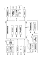
- the vehicle system 1 includes, for example, a camera 10, a radar device 12, a finder 14, an object recognition device 16, a communication device 20, an HMI (Human Machine Interface) 30, a vehicle sensor 40, and a navigation device 50; An MPU (Map Positioning Unit) 60, a projection unit 70, a drive operator 80, an automatic driving control device (an example of a vehicle control device) 100, a traveling driving force output device 200, a brake device 210, a steering device 220 And These devices and devices are mutually connected by a multiplex communication line such as a CAN (Controller Area Network) communication line, a serial communication line, a wireless communication network or the like.
- CAN Controller Area Network
- serial communication line a wireless communication network or the like.
- the camera 10 is, for example, a digital camera using a solid-state imaging device such as a charge coupled device (CCD) or a complementary metal oxide semiconductor (CMOS).
- CMOS complementary metal oxide semiconductor
- One or more cameras 10 are attached to any part of a vehicle (hereinafter referred to as a host vehicle M) on which the vehicle system 1 is mounted.
- the camera 10 When imaging the front, the camera 10 is attached to the top of the front windshield, the rear surface of the rearview mirror, or the like.
- the camera 10 periodically and repeatedly captures the periphery of the vehicle M.
- the camera 10 may be a stereo camera.
- the radar apparatus 12 emits radio waves such as millimeter waves around the host vehicle M, and detects radio waves (reflected waves) reflected by the object to detect at least the position (distance and direction) of the object.
- radio waves such as millimeter waves around the host vehicle M
- the radar device 12 may detect the position and the velocity of the object by a frequency modulated continuous wave (FM-CW) method.
- FM-CW frequency modulated continuous wave
- the finder 14 is a light detection and ranging (LIDAR).
- the finder 14 irradiates light around the host vehicle M and measures scattered light.
- the finder 14 detects the distance to the object based on the time from light emission to light reception.
- the light to be irradiated is, for example, pulsed laser light.
- One or more finders 14 are attached to any part of the host vehicle M.
- the object recognition device 16 performs sensor fusion processing on the detection result of a part or all of the camera 10, the radar device 12, and the finder 14 to recognize the position, the type, the speed, and the like of the object.
- the object recognition device 16 outputs the recognition result to the automatic driving control device 100.
- the object recognition device 16 may output the detection results of the camera 10, the radar device 12, and the finder 14 to the automatic driving control device 100 as it is, as necessary.
- the communication device 20 communicates with other vehicles around the host vehicle M, for example, using a cellular network, Wi-Fi network, Bluetooth (registered trademark), DSRC (Dedicated Short Range Communication), or the like It communicates with various server devices via the base station.
- a cellular network for example, using a cellular network, Wi-Fi network, Bluetooth (registered trademark), DSRC (Dedicated Short Range Communication), or the like It communicates with various server devices via the base station.
- the HMI 30 presents various information to the occupant of the host vehicle M, and accepts input operation by the occupant.
- the HMI 30 includes various display devices, speakers, a buzzer, a touch panel, switches (for example, hazard switches), keys, and the like.
- the vehicle sensor 40 includes a vehicle speed sensor that detects the speed of the host vehicle M, an acceleration sensor that detects acceleration, a yaw rate sensor that detects an angular velocity around the vertical axis, and an azimuth sensor that detects the direction of the host vehicle M.
- the navigation device 50 includes, for example, a GNSS (Global Navigation Satellite System) receiver 51, a navigation HMI 52, and a path determination unit 53, and stores the first map information 54 in a storage device such as an HDD (Hard Disk Drive) or a flash memory. Hold
- the GNSS receiver 51 specifies the position of the host vehicle M based on the signal received from the GNSS satellite. The position of the host vehicle M may be identified or supplemented by an INS (Inertial Navigation System) using the output of the vehicle sensor 40.
- the navigation HMI 52 includes a display device, a speaker, a touch panel, keys and the like. The navigation HMI 52 may be partially or entirely shared with the above-described HMI 30.
- the route determination unit 53 for example, a route from the position of the host vehicle M specified by the GNSS receiver 51 (or an arbitrary position input) to the destination input by the occupant using the navigation HMI 52 (hereinafter referred to as The route on the map is determined with reference to the first map information 54.
- the first map information 54 is, for example, information in which a road shape is represented by a link indicating a road and a node connected by the link.
- the first map information 54 may include road curvature, POI (Point Of Interest) information, and the like.
- the on-map route determined by the route determination unit 53 is output to the MPU 60.
- the navigation device 50 may also perform route guidance using the navigation HMI 52 based on the on-map route determined by the route determination unit 53.
- the navigation device 50 may be realized by, for example, the function of a terminal device such as a smartphone or a tablet terminal owned by a passenger.
- the navigation device 50 may transmit the current position and the destination to the navigation server via the communication device 20, and acquire the on-map route returned from the navigation server.
- the MPU 60 functions as, for example, the recommended lane determination unit 61, and holds the second map information 62 in a storage device such as an HDD or a flash memory.
- the recommended lane determination unit 61 divides the route provided from the navigation device 50 into a plurality of blocks (for example, in units of 100 [m] in the traveling direction of the vehicle), and refers to the second map information 62 for each block. Determine the recommended lanes.
- the recommended lane determination unit 61 determines which lane to travel from the left.
- the recommended lane determination unit 61 determines the recommended lane so that the host vehicle M can travel on a reasonable route for traveling to a branch destination when a branch point, a junction point, or the like is present in the route.
- the second map information 62 is map information that is more accurate than the first map information 54.
- the second map information 62 includes, for example, information on the center of the lane or information on the boundary of the lane.
- the second map information 62 may include road information, traffic regulation information, address information (address / zip code), facility information, telephone number information, and the like.
- the second map information 62 may be updated as needed by accessing another device using the communication device 20.
- the projection unit 70 is, for example, a projector.
- the projection unit 70 projects an image on the traveling path of the host vehicle M at a timing instructed by the projection control unit 180.
- the travel path is an area where the host vehicle M can travel.
- the traveling path may be a lane divided by road division lines, or may be a road on which there is no road division line such as an alley and on which a vehicle can travel.
- a sidewalk or the like divided from the roadway by a level difference or a guardrail may not be included in the traveling path.
- the operating element 80 includes, for example, an accelerator pedal, a brake pedal, a shift lever, a steering wheel, a modified steering wheel, a joystick and other operating elements.
- a sensor for detecting the amount of operation or the presence or absence of an operation is attached to the driving operation element 80, and the detection result is the automatic driving control device 100 or the traveling driving force output device 200, the brake device 210, and the steering device. It is output to one or both of 220.
- the automatic driving control apparatus 100 includes, for example, a first control unit 120, a second control unit 160, and a projection control unit 180.
- Each of the first control unit 120, the second control unit 160, and the projection control unit 180 is realized, for example, when a hardware processor such as a central processing unit (CPU) executes a program (software).
- a hardware processor such as a central processing unit (CPU) executes a program (software).
- some or all of these components may be hardware (circuits) such as LSI (Large Scale Integration), ASIC (Application Specific Integrated Circuit), FPGA (Field-Programmable Gate Array), GPU (Graphics Processing Unit), etc. Circuit (including circuitry) or may be realized by cooperation of software and hardware.
- FIG. 2 is a functional configuration diagram of the first control unit 120, the second control unit 160, and the projection control unit 180.
- the first control unit 120 includes, for example, a recognition unit 130 and an action plan generation unit 140.
- the recognition unit 130 includes, for example, a road width recognition unit 132, a pedestrian recognition unit 134, an overtaking possibility determination unit 136, and a walking difficulty area estimation unit 138.
- the action plan generation unit 140 includes, for example, a follow-up operation control unit 142 and an overtaking operation control unit 144.
- the combination of the overtaking possibility determination unit 136, the walking difficulty area estimating unit 138, the follow-up operation control unit 142, the overtaking operation control unit 144, and the second control unit 160 is an example of the “operation control unit”.
- the first control unit 120 implements, for example, a function by artificial intelligence (AI) and a function by a predetermined model in parallel.
- AI artificial intelligence
- the function "Recognize intersections" includes recognition of intersections by an image recognition method using deep learning etc. and recognition based on predetermined conditions (such as signals capable of pattern matching, road markings, etc.) It is realized by scoring both and evaluating them comprehensively. This ensures the reliability of automatic driving.
- the recognition unit 130 detects the position of an object in the vicinity of the host vehicle M, the state of the velocity, the acceleration, and the like based on information input from the camera 10, the radar device 12, and the finder 14 via the object recognition device 16. recognize.
- Objects include oncoming vehicles and stationary obstacles.
- the position of the object is recognized as, for example, a position on an absolute coordinate with the representative point (the center of gravity, the center of the drive axis, etc.) of the host vehicle M as the origin, and used for control.
- the position of the object may be represented by a representative point such as the center of gravity or a corner of the object, or may be represented by a represented region.
- the "state" of an object may include the acceleration or jerk of the object, or "action state” (e.g.
- the recognition unit 130 recognizes the shape of a curve through which the host vehicle M passes from now on the basis of the captured image of the camera 10.
- the recognition unit 130 converts the shape of the curve from the captured image of the camera 10 to a real plane, and for example, information indicating the shape of the curve which is expressed using two-dimensional point sequence information or a model equivalent thereto. Output to the action plan generation unit 140.
- the recognition unit 130 recognizes a lane in which the host vehicle M is traveling (traveling lane).
- the recognition unit 130 may use a pattern of road division lines obtained from the second map information 62 (for example, an array of solid lines and broken lines) and road division lines around the host vehicle M recognized from an image captured by the camera 10
- the traveling lane is recognized by comparing with the pattern of.
- the recognition unit 130 may recognize the traveling lane by recognizing a road boundary (road boundary) including not only road division lines but also road division lines, road shoulders, curbs, median separators, guard rails and the like. .
- the position of the host vehicle M acquired from the navigation device 50 or the processing result by the INS may be added.
- the recognition unit 130 also recognizes a stop line, a road sign, a red light, a toll booth, and other road events.
- the recognition unit 130 recognizes the position and orientation of the host vehicle M with respect to the traveling lane when recognizing the traveling lane.
- the recognition unit 130 is, for example, a deviation of the reference point of the host vehicle M from the center of the lane, and an angle formed by a line connecting the center of the lane in the traveling direction of the host vehicle M It may be recognized as an attitude. Also, instead of this, the recognition unit 130 sets the position of the reference point of the host vehicle M with respect to any one side end (road segment or road boundary) of the travel lane relative to the host vehicle M with respect to the travel lane. It may be recognized as
- the recognition unit 130 may derive recognition accuracy in the above-described recognition processing, and output the recognition accuracy to the action plan generation unit 140 as recognition accuracy information.
- the recognition unit 130 generates recognition accuracy information based on the frequency at which a road marking can be recognized in a fixed period. The functions of the road width recognition unit 132, the pedestrian recognition unit 134, the overtaking permission determination unit 136, and the difficult walking area estimation unit 138 of the recognition unit 130 will be described later.
- the action plan generation unit 140 travels in the recommended lane determined by the recommended lane determination unit 61 in principle, and is further sequentially executed in automatic driving so as to correspond to the surrounding situation of the host vehicle M.
- the functions of the follow-up operation control unit 142 and the overtaking operation control unit 144 of the action plan generation unit 140 will be described later.
- the second control unit 160 includes, for example, an acquisition unit 162, a speed control unit 164, and a steering control unit 166.
- the acquisition unit 162 acquires information on the target trajectory (orbit point) generated by the action plan generation unit 140, and stores the information in a memory (not shown).
- the speed control unit 164 controls the traveling drive power output device 200 or the brake device 210 based on the speed component associated with the target track stored in the memory.
- the steering control unit 166 controls the steering device 220 according to the degree of bending of the target track stored in the memory.
- the processing of the speed control unit 164 and the steering control unit 166 is realized by, for example, a combination of feedforward control and feedback control.
- the steering control unit 166 combines feedforward control according to the curvature of the road ahead of the host vehicle M and feedback control based on the deviation from the target track.
- the projection control unit 180 uses the projection unit 70 to display an image indicating a target trajectory of the own vehicle M, which is generated by the action plan generation unit 140, the follow-up operation control unit 142, or the overtaking operation control unit 144. Project on the road. Details of the function of the projection control unit 180 will be described later.
- the traveling driving force output device 200 outputs traveling driving force (torque) for the vehicle to travel to the driving wheels.
- the traveling driving force output device 200 includes, for example, a combination of an internal combustion engine, an electric motor, a transmission, and the like, and an ECU that controls these.
- the ECU controls the above configuration in accordance with the information input from the second control unit 160 or the information input from the drive operator 80.
- the brake device 210 includes, for example, a brake caliper, a cylinder that transmits hydraulic pressure to the brake caliper, an electric motor that generates hydraulic pressure in the cylinder, and a brake ECU.
- the brake ECU controls the electric motor in accordance with the information input from the second control unit 160 or the information input from the drive operator 80 so that the brake torque corresponding to the braking operation is output to each wheel.
- the brake device 210 may include, as a backup, a mechanism for transmitting the hydraulic pressure generated by the operation of the brake pedal included in the drive operator 80 to the cylinder via the master cylinder.
- the brake device 210 is not limited to the configuration described above, and is an electronically controlled hydraulic brake device that controls the actuator according to the information input from the second control unit 160 to transmit the hydraulic pressure of the master cylinder to the cylinder It is also good.
- the steering device 220 includes, for example, a steering ECU and an electric motor.
- the electric motor for example, applies a force to the rack and pinion mechanism to change the direction of the steered wheels.
- the steering ECU drives the electric motor to change the direction of the steered wheels in accordance with the information input from the second control unit 160 or the information input from the drive operator 80.
- the road width recognition unit 132 recognizes the road width of the traveling path on which the vehicle M travels. For example, the road width recognition unit 132 recognizes road division lines on the left and right when viewed from the position of the host vehicle M from the captured image of the camera 10, and recognizes the distance between the recognized left and right division lines as the width of the road. Do. In addition, the road width recognition unit 132 may recognize the width of the road on which the host vehicle M travels by collating the position of the host vehicle M with the first map information 54 or the second map information 62.
- the pedestrian recognition unit 134 recognizes a pedestrian present in the vicinity of the host vehicle M.
- the pedestrian recognition unit 134 may operate when the road width recognized by the road width recognition unit 132 is equal to or less than a predetermined width (for example, about 4 m or less).
- the pedestrian recognition unit 134 operates when the vehicle M is traveling on a road having a narrower width than a national road or a prefectural road, or a road on which a pedestrian is likely to walk. It may be.
- the pedestrian recognition unit 134 recognizes, for example, the presence of a pedestrian on the traveling road in the traveling direction of the vehicle M (hereinafter referred to as the front) from the captured image of the camera 10. Further, the pedestrian recognition unit 134 recognizes the position, the moving speed, and the moving direction of the pedestrian. The pedestrian recognition unit 134 may also recognize the relative position, relative velocity, and relative movement direction of the pedestrian viewed from the host vehicle M.
- the overtaking permission determination unit 136 determines whether the own vehicle M can pass the pedestrian or not. judge.
- FIG. 3 is a diagram for explaining the process of the overtaking possibility determination unit 136.
- pedestrians P1 to P3 exist in front of the host vehicle M traveling on the traveling path R1.
- the vehicle M travels at a speed VM in the traveling direction, and the pedestrians P1 and P2 move at speeds V1 and V2 in substantially the same direction as the traveling direction of the vehicle M, respectively.
- the substantially the same direction includes not only the same direction as the traveling direction of the host vehicle M but also a predetermined error range (for example, about -15 degrees to about 15 degrees).
- the pedestrian P3 is an opposite pedestrian who walks at the speed V3 in opposition to the host vehicle M.
- the position and velocity V1 to V3 of the pedestrians P1 to P3 are recognized by the pedestrian recognition unit 134.
- the overtaking permission determination unit 136 performs overtaking permission determination in order from the pedestrian closest to the host vehicle M. Overtaking permission determination unit 136 sets distance W1L from the position of pedestrian P1 to left end R1L of traveling path R1 and distance W1R from right end RIR to pedestrian P1 present closest to host vehicle M. Calculate Then, on the basis of the vehicle width WM of the host vehicle M and the calculated distances W1L and W1R, the overtaking permission determination unit 136 determines whether or not the host vehicle M can pass by the side of the pedestrian P1.
- the overtaking permission determination unit 136 determines that judge.
- the margin width is a width secured for the host vehicle M to pass the side of the pedestrian P1, and is, for example, about 0.3 [m]. Further, the overtaking permission determination unit 136 determines that the host vehicle M can pass the pedestrian M if the width WM ′ is equal to or less than the distances W1L and W1R.
- the overtaking permission determination unit 136 performs the same process as the above-described overtaking permission determination process for the pedestrian P1 for the pedestrians P2 and P3. In addition, since the pedestrian P3 is an opposite pedestrian, it is predicted that the host vehicle M will be visually recognized immediately and the host vehicle M will be avoided. Therefore, the overtaking determination unit 136 may not perform the overtaking determination process on the pedestrian P3.
- the overtaking possibility determination unit 136 determines whether the pedestrian P1 closest to the host vehicle M can not be overtaken. Therefore, when it is determined that the pedestrian P1 closest to the host vehicle M can not be overtaken among the plurality of pedestrians recognized by the pedestrian recognition unit 134, the overtaking permission determination unit 136 walks ahead of the pedestrian P1. It may also be determined that the parties P2 and P3 can not pass.
- the follow-up operation control unit 142 is recognized by the pedestrian recognition unit 134 when the road width of the travel path R1 recognized by the road width recognition unit 132 is equal to or less than a predetermined width (for example, about 3.5 m).
- the traveling direction of the pedestrians P1 to P3 is substantially the same as the traveling direction of the vehicle M, and the vehicle M travels so as to follow the pedestrian with high priority.
- a pedestrian with a high priority is, for example, a pedestrian closest to the host vehicle M.
- the following operation control unit 142 makes the traveling direction substantially the same as that of the own vehicle M, and A target trajectory is generated that follows and follows a nearby pedestrian P1.
- the pedestrian recognition unit 134 recognizes the relative distance D1 between the host vehicle M and the pedestrian P1.
- the follow-up operation control unit 142 generates a target trajectory in which the speed VM of the host vehicle M is changed based on the relative distance and the speed V1 of the pedestrian P1.
- the follow-up operation control unit 142 determines that the speed difference between the traveling speed VM of the host vehicle M and the speed V1 of the pedestrian P1 is within a predetermined speed (eg, about ⁇ 3 [km / h]) and The target trajectory is generated such that the error of the relative distance D1 is within a predetermined distance (for example, about ⁇ 3 [m]). Thereby, the follow-up operation control unit 142 can cause the host vehicle M to follow the pedestrian P1 while maintaining the relative distance to the pedestrian P1 to some extent. As described above, by causing the own vehicle M to follow the pedestrian P1, the presence of the own vehicle M can be noticed by the pedestrian P1 and moved to the roadside.
- a predetermined speed eg, about ⁇ 3 [km / h]
- the target trajectory is generated such that the error of the relative distance D1 is within a predetermined distance (for example, about ⁇ 3 [m]).
- FIG. 4 is a diagram for explaining that the follow-up operation control unit 142 brings the host vehicle M close to one side of the traveling route R1 and causes the vehicle to follow.
- the control for the pedestrian P1 will be described for convenience of explanation, but when the pedestrian traveling in the substantially same direction ahead of the host vehicle M1 is replaced by another pedestrian, the walk Perform the same process on the
- the follow-up operation control unit 142 compares the distance W1L from the position of the pedestrian P1 to the left roadside R1L with the distance W1R from the position of the pedestrian P1 to the right roadside R1R, and moves the vehicle M toward the roadside To make it follow and run.
- the follow-up operation control unit 142 moves the host vehicle M to the right of the traveling path R1 and follows the pedestrian P1.
- the pedestrian P1 recognizes the presence of the host vehicle M, the pedestrian P1 can easily move to the left side of the travel path R1.
- the overtaking operation control unit 144 causes the pedestrian P1 from the other side. Generate a target trajectory for overtaking. Having a predetermined distance or more in one of the width directions means, for example, that the position of the pedestrian P1 is within a predetermined distance (for example, about 0.5 [m]) from one road side of the traveling path R1. . The distance from the position of the pedestrian P1 to the road side on the other side of the traveling path R1 is larger than the width WM ′ by being deviated by a predetermined degree or more in one of the width directions.
- the position of the pedestrian P1 is Even if one side in the width direction of the travel path R1 is not deviated by a predetermined degree or more, a target track for passing the pedestrian P1 may be generated.
- the pedestrian recognition unit 134 determines whether the pedestrian P1 turns around or not based on the behavior of the head or upper body captured by the captured image of the camera 10. Specifically, the pedestrian recognition unit 134 has feature information (for example, eyes or mouth) of the face of the pedestrian P1 from the captured image of the camera 10 mounted on the host vehicle M traveling following the pedestrian P1. If it can be recognized, it is determined that the pedestrian P1 turns around.
- feature information for example, eyes or mouth
- pedestrian recognition unit 134 recognizes the eye of the pedestrian P1 from the captured image
- the pedestrian recognition unit 134 recognizes the sight line direction based on the positional relationship between the recognized eye and the iris.
- pedestrian recognition part 134 may judge that pedestrian P1 turned around, when a gaze direction recognized is a direction where self-vehicles M exist.
- the pedestrian recognition unit 134 estimates the rotation angle of the head from the captured image of the camera 10, and the estimated rotation angle of the head is a predetermined angle (for example, 90 degrees based on the traveling direction of the pedestrian P1). ] Or more), it may be judged that pedestrian P1 turned around. In this case, the pedestrian recognition unit 134 estimates the rotation angle of the head based on the displacement of the position of the feature information (for example, the ear) of the head obtained from the captured image of the camera 10, for example.
- the pedestrian recognition unit 134 estimates the rotation angle of the upper body of the pedestrian P1 instead of (or in addition to) the rotation angle of the head of the pedestrian P1 and estimates the rotation angle of the upper body, When the angle is equal to or more than a predetermined angle (for example, about 90 degrees), it may be determined that the pedestrian P1 turns around.
- a predetermined angle for example, about 90 degrees
- the overtaking permission determination unit 136 determines that the pedestrian P1 can be overtaken.
- the overtaking operation control unit 144 generates a target trajectory for passing the pedestrian P1 when the overtaking permission determination unit 136 determines that the host vehicle M can pass the pedestrian P1.
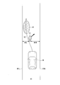
- FIG. 5 is a diagram for explaining the process of the overtaking operation control unit 144.
- the overtaking operation control unit 144 predicts the position, moving speed, and moving direction of the pedestrian P1 after turning around, and sets the target potential area Pa1 based on the predicted result.
- the target potential is, for example, an index indicating the degree of possibility that the host vehicle M contacts an object (for example, a pedestrian). Also, the target potential region is set to be lower as it is farther from the object.
- the overtaking operation control unit 144 moves to the left roadside R1L closer to the roadside among the left roadside R1L and the right roadside R1R so that the pedestrian P1 after turning turns overtakes the host vehicle M. And the position of the pedestrian P1 after a predetermined time is predicted based on the current position of the pedestrian P1, the moving speed, and the moving direction. Then, the overtaking operation control unit 144 generates a target trajectory K1 that passes through a region not in contact with the target potential region Pa1. The follow-up operation by the follow-up operation control unit 142 is performed in parallel until the overtaking operation control along the target track K1 generated by the overtaking operation control unit 144 is executed.
- the overtaking operation control unit 144 determines whether the distance W1R between the pedestrian P1 and the right road side R1R of the travel path R1 is larger than the width WM '. In addition, when the pedestrian recognition unit 134 recognizes that the pedestrian P1 has turned around, the overtaking driving control unit 144 estimates that the pedestrian can recognize the presence of the own vehicle M, Determination of whether or not the pedestrian P1 can be overtaken by making the margin width to be added to the width WM smaller than the margin width when the pedestrian P1 is not turning around (for example, about 0.15 [m]) You may
- the overtaking operation control unit 144 When the distance W1R is not equal to or less than the width WM ', the overtaking operation control unit 144 does not execute the overtaking operation along the target track K1, and the following operation by the following operation control unit 142 is continued. Further, when the distance W1R is larger than the width WM ′, the overtaking operation control unit 144 executes the overtaking operation of the host vehicle M along the target track K1.
- the walking difficulty area estimating unit 138 estimates an area where walking of the pedestrian present on the traveling path R1 is difficult.
- An area where walking is difficult means that the pedestrian can walk, but it is estimated that walking on the area is highly likely that the shoes or clothes of the pedestrian may get wet or become dirty, or that the pedestrian may fall. It is.
- the area where walking is difficult is, for example, an area of a puddle, an area where the road surface is frozen, or an area where the road surface is uneven.
- the walking difficulty area estimating unit 138 estimates the water pooling area, the frozen area, and the uneven area by comparing the luminance information of the road surface of the traveling path R1 with the luminance information of the reference road surface from the captured image of the camera 10. In addition, the walking difficulty area estimating unit 138 acquires the shape of the road surface from the captured image of the camera 10, and it is determined that the pedestrian is difficult to walk when the unevenness degree of the road surface is equal to or higher than a predetermined reference degree. It may be estimated.
- the passing driving control unit 144 estimates that it is difficult for the pedestrian to walk when a target trajectory for passing the pedestrian is generated and a region where walking of the pedestrian is difficult is estimated on the traveling route R1.
- a target trajectory is generated such that the vehicle M passes through the area to be
- FIG. 6 is a diagram for explaining the process of the overtaking operation control unit 144 when it is estimated that there is a walking difficulty area.
- the area A1 of the water pool is shown on the traveling path R1.
- the overtaking operation control unit 144 generates a target trajectory K2 for causing the host vehicle M to pass the area A1 and overtaking the pedestrian P1 when the walking difficulty area estimating unit 138 estimates that there is a puddle area A1. .
- the pedestrian P1 can move to the avoidable area other than the area A1 of the puddle.
- the projection control unit 180 causes the projection unit 70 to project an image prompting the pedestrian to avoid the host vehicle M on the traveling path R1.
- the image prompting the pedestrian to avoid the host vehicle M may be, for example, an image indicating a direction in which the pedestrian avoids the host vehicle M, or an image indicating an area in which the host vehicle M travels.
- FIG. 7 is a diagram for explaining that the projection control unit 180 projects an image showing an area where the pedestrian walks on the traveling path R1.
- the follow-up operation control unit 142 generates and generates an image IM1 for moving the pedestrian P1 to the left road side R1L when there is no road width overtaking the pedestrian P1 and traveling while following the pedestrian P1.
- the image IM1 is projected by the projection unit 70 on a predetermined area on the left roadside R1L side of the travel path R1 and in front of the pedestrian P1.
- the predetermined area in front is an area included in a range that is a few [m] ahead of the current position of the pedestrian P1, and is an area where the pedestrian P1 is easily visible even while walking.
- the pedestrian position image IM1 may be, for example, an image indicating an area, an image including characters such as a “walking area” or the like, or a combination thereof. By projecting character information such as “walking area”, it is possible to make the pedestrian P1 easily grasp the walking area which is not affected when the host vehicle M passes. Further, by projecting the image IM1 by the projection control unit 180, it is possible to make the pedestrian P1 grasp what position it should move.
- FIG. 8 is a diagram for explaining that an image showing a region in which the host vehicle M travels is projected by the projection control unit 180 onto the traveling path R1.
- the projection control unit 180 selects one of the image IM2 indicating the traveling area of the host vehicle M and the image IM3 indicating the target trajectory based on the target trajectory K1 generated by the overtaking operation control unit 144, for example.
- both are projected onto the traveling path R1 by the projection unit 70.
- the image IM2 may be, for example, an image indicating an area, an image including characters such as a “vehicle travel area”, or the like, or a combination thereof.
- the pedestrian P1 can easily grasp the area through which the host vehicle M passes, and it is possible to urge movement to an area outside the vehicle travel area.
- the projection control unit 180 may change the color or pattern of the images IM1 to IM3 to be projected based on travel conditions such as the weather or the time zone, and even if an animation corresponding to the images IM1 to IM3 is displayed. Good.
- the pedestrian P1 By projecting the images IM1 to IM3 by the projection control unit 180, the pedestrian P1 can be quickly moved to the roadside along the traveling path R1. If the pedestrian recognition unit 134 recognizes that the pedestrian P1 has avoided after the projection control unit 180 projects at least one of the images IM1 to IM3, the overtaking operation control unit 144 causes the pedestrian P1 to Execute overtaking operation control. For example, after the host vehicle M overtakes the pedestrian P1, the projection control unit 180 ends the projection of the images IM1 to IM3.
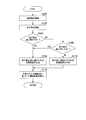
- FIG. 9 is a flowchart showing an example of processing executed by the automatic driving control apparatus 100 according to the embodiment.
- the process of this flowchart may be repeatedly performed, for example, at a predetermined cycle or at a predetermined timing while the automatic driving of the host vehicle M is being performed.
- the road width recognition unit 132 recognizes the road width of the travel route R1 of the host vehicle M (step S100).
- the pedestrian recognition unit 134 recognizes a pedestrian in front of the host vehicle M and present on the traveling route R1 on which the host vehicle M travels (step S102).
- whether or not the overtaking permission determination unit 136 overtakes the pedestrian based on the road width of the traveling route R1 recognized by the road width recognition unit 132 and the position of the pedestrian recognized by the pedestrian recognition unit 134 It is determined whether or not (step S104). For example, when it is determined that the road width of the travel path R1 is equal to or less than the predetermined width and the pedestrian can not be passed, the pedestrian recognition unit 134 determines whether the pedestrian turns around (step S106).
- step S104 If it is determined in the process of step S104 that the pedestrian can be overtaken, or if the pedestrian turns around in the process of step S106, the overtaking operation control unit 144 generates a target trajectory for overtaking the pedestrian (step S104). S108). Further, in step S106, when the pedestrian is not turning around, for example, the follow-up operation control unit 142 proceeds in substantially the same direction as the host vehicle M and has high priority (for example, the pedestrian closest to the host vehicle M) A target trajectory for following is generated (step S110). Next, the second control unit 160 executes operation control based on the generated target trajectory (step S112). Thus, the processing of this flowchart is ended.
- the overtaking operation control unit 144 or the follow-up operation control unit 142 When the target trajectory is generated in the process of step S108 or step S110 described above, the overtaking operation control unit 144 or the follow-up operation control unit 142 generates the target trajectory in consideration of the estimation result by the difficult walking area estimation unit 138. You may Moreover, when performing driving control in the process of step S112 mentioned above, the 2nd control part 160 may make the projection part 70 project the image which urges a pedestrian to avoid the own vehicle M.
- the width of the recognized road is equal to or less than the predetermined width.
- the traveling direction is substantially the same as that of the vehicle M, and the pedestrian M avoids the roadside by causing the vehicle M to travel so as to follow the pedestrian with high priority. Otherwise, appropriate driving control can be performed under road conditions such that the vehicle can not pass a pedestrian.
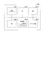
- FIG. 10 is a diagram illustrating an example of a hardware configuration of the automatic driving control device 100 according to the embodiment.
- the automatic operation control device 100 includes a communication controller 100-1, a CPU 100-2, a RAM 100-3, a ROM 100-4, a secondary storage device 100-5 such as a flash memory or HDD, and a drive device 100-6, or an internal bus or It is configured to be mutually connected by a dedicated communication line.
- a portable storage medium such as an optical disk is attached to the drive device 100-6.
- the program 100-5a stored in the secondary storage device 100-5 is expanded on the RAM 100-3 by a DMA controller (not shown) or the like, and is executed by the CPU 100-2 to execute the first control unit 120 and the second control unit 120.
- the control unit 160 is realized.
- the program referred to by the CPU 100-2 may be stored in a portable storage medium attached to the drive device 100-6, or may be downloaded from another device via the network NW.
- a storage device for storing information;
- a hardware processor that executes a program stored in the storage device;
- the hardware processor executes the program to Road width recognition processing that recognizes the width of the road on which the vehicle travels;
- Pedestrian recognition processing for recognizing a pedestrian existing around the vehicle;
- a driving control process for controlling one or both of steering and acceleration / deceleration of the vehicle to travel the vehicle regardless of the operation of the occupant of the vehicle, the road recognized by the road width recognition process
- the traveling direction of the pedestrians recognized by the pedestrian recognition processing is substantially the same as the vehicle and follows the pedestrians with high priority.
- Operation control processing for causing the vehicle to travel; Is configured to run, Vehicle control device.
- SYMBOLS 1 ... Vehicle system, 10 ... Camera, 12 ... Radar apparatus, 14 ... Finder, 16 ... Object recognition apparatus, 20 ... Communication apparatus, 30 ... HMI, 32 ... Automatic driving start switch, 40 ... Vehicle sensor, 50 ... Navigation apparatus, DESCRIPTION OF SYMBOLS 60 ... MPU, 70 ... Projection part, 80 ... Driving operator, 100 ... Automatic driving control apparatus, 120 ... 1st control part, 130 ... Recognition part, 132 ... Road width recognition part, 134 ... Pedestrian recognition part, 136 ...
- Overtaking possibility determination unit 138 walking difficulty area estimation unit 140: action plan generation unit 142: follow-up operation control unit 144: overtaking operation control unit 160: second control unit 180: projection control unit 200: traveling Driving force output device, 210: brake device, 220: steering device, M: own vehicle
Landscapes
- Engineering & Computer Science (AREA)
- Mechanical Engineering (AREA)
- Transportation (AREA)
- Automation & Control Theory (AREA)
- Physics & Mathematics (AREA)
- General Physics & Mathematics (AREA)
- Human Computer Interaction (AREA)
- Radar, Positioning & Navigation (AREA)
- Remote Sensing (AREA)
- Theoretical Computer Science (AREA)
- Multimedia (AREA)
- Chemical & Material Sciences (AREA)
- Combustion & Propulsion (AREA)
- Electromagnetism (AREA)
- Computer Networks & Wireless Communication (AREA)
- Traffic Control Systems (AREA)
- Control Of Driving Devices And Active Controlling Of Vehicle (AREA)
- Lighting Device Outwards From Vehicle And Optical Signal (AREA)
Abstract
La présente invention concerne un dispositif de commande de véhicule comprenant : une unité de reconnaissance de largeur de chaussée pour reconnaître la largeur d'une chaussée sur laquelle se déplace un véhicule; une unité de reconnaissance de piéton pour reconnaître un piéton présent autour du véhicule; et une unité de commande de conduite pour déplacer le véhicule par une commande de direction et/ou d'accélération/de décélération du véhicule indépendamment de toute autre opération effectuée par le conducteur du véhicule. Lorsque la largeur de la chaussée reconnue par l'unité de reconnaissance de largeur de chaussée est égale ou inférieure à une largeur prédéfinie, l'unité de commande de conduite commande le véhicule de sorte que le véhicule se déplace pour suivre un piéton qui marche dans une direction qui est sensiblement la même que la direction de déplacement du véhicule et qui a une grande priorité parmi des piétons reconnus par l'unité de reconnaissance de piéton.
Priority Applications (5)
| Application Number | Priority Date | Filing Date | Title |
|---|---|---|---|
| DE112017007906.3T DE112017007906T5 (de) | 2017-10-05 | 2017-10-05 | Fahrzeugsteuervorrichtung, fahrzeugsteuerverfahren und programm |
| US16/650,395 US20200290643A1 (en) | 2017-10-05 | 2017-10-05 | Vehicle control device, vehicle control method, and program |
| JP2019546482A JP6768974B2 (ja) | 2017-10-05 | 2017-10-05 | 車両制御装置、車両制御方法、およびプログラム |
| PCT/JP2017/036282 WO2019069425A1 (fr) | 2017-10-05 | 2017-10-05 | Dispositif de commande de véhicule, procédé de commande de véhicule et programme |
| CN201780095158.3A CN111133489B (zh) | 2017-10-05 | 2017-10-05 | 车辆控制装置、车辆控制方法及存储介质 |
Applications Claiming Priority (1)
| Application Number | Priority Date | Filing Date | Title |
|---|---|---|---|
| PCT/JP2017/036282 WO2019069425A1 (fr) | 2017-10-05 | 2017-10-05 | Dispositif de commande de véhicule, procédé de commande de véhicule et programme |
Publications (1)
| Publication Number | Publication Date |
|---|---|
| WO2019069425A1 true WO2019069425A1 (fr) | 2019-04-11 |
Family
ID=65994199
Family Applications (1)
| Application Number | Title | Priority Date | Filing Date |
|---|---|---|---|
| PCT/JP2017/036282 WO2019069425A1 (fr) | 2017-10-05 | 2017-10-05 | Dispositif de commande de véhicule, procédé de commande de véhicule et programme |
Country Status (5)
| Country | Link |
|---|---|
| US (1) | US20200290643A1 (fr) |
| JP (1) | JP6768974B2 (fr) |
| CN (1) | CN111133489B (fr) |
| DE (1) | DE112017007906T5 (fr) |
| WO (1) | WO2019069425A1 (fr) |
Cited By (4)
| Publication number | Priority date | Publication date | Assignee | Title |
|---|---|---|---|---|
| CN112141097A (zh) * | 2019-06-26 | 2020-12-29 | 本田技研工业株式会社 | 车辆控制装置、车辆控制方法及存储介质 |
| JP2021046023A (ja) * | 2019-09-17 | 2021-03-25 | 株式会社Subaru | 自動運転車両における報知装置および報知方法 |
| CN113366400A (zh) * | 2019-12-20 | 2021-09-07 | 百度时代网络技术(北京)有限公司 | 自动驾驶车辆的动态成本函数的实现方法 |
| CN113994408A (zh) * | 2019-06-14 | 2022-01-28 | 索尼集团公司 | 信息处理装置、信息处理方法和程序 |
Families Citing this family (8)
| Publication number | Priority date | Publication date | Assignee | Title |
|---|---|---|---|---|
| WO2019089591A1 (fr) * | 2017-10-30 | 2019-05-09 | Mobileye Vision Technologies Ltd. | Circulation d'un véhicule sur la base d'une activité humaine |
| JP7100998B2 (ja) * | 2018-03-08 | 2022-07-14 | 本田技研工業株式会社 | 車両制御装置、車両制御方法、およびプログラム |
| KR102370976B1 (ko) * | 2020-10-29 | 2022-03-04 | 한국교통대학교산학협력단 | 객체 특징점을 이용한 차선 변경 지원 시스템 |
| JP7264142B2 (ja) * | 2020-11-02 | 2023-04-25 | トヨタ自動車株式会社 | 路面種類推定装置および車両制御システム |
| DE102020214131B3 (de) | 2020-11-10 | 2022-02-10 | Volkswagen Aktiengesellschaft | Verfahren zum automatisierten Einparken eines Kraftfahrzeugs und Kraftfahrzeug |
| JP7435483B2 (ja) * | 2021-01-12 | 2024-02-21 | トヨタ自動車株式会社 | 地図生成装置、地図生成方法及び地図生成用コンピュータプログラム |
| JP2022113949A (ja) * | 2021-01-26 | 2022-08-05 | 本田技研工業株式会社 | 移動体制御装置、移動体制御方法、およびプログラム |
| FR3133813A1 (fr) * | 2022-03-23 | 2023-09-29 | Psa Automobiles Sa | Méthodes et systèmes de conduite d’un véhicule automobile |
Citations (3)
| Publication number | Priority date | Publication date | Assignee | Title |
|---|---|---|---|---|
| JP2005227952A (ja) * | 2004-02-12 | 2005-08-25 | Nissan Motor Co Ltd | 走行状況アドバイスシステム |
| JP2009003497A (ja) * | 2007-06-19 | 2009-01-08 | Mazda Motor Corp | 歩行者検出装置 |
| JP2010198578A (ja) * | 2009-02-27 | 2010-09-09 | Toyota Motor Corp | 移動軌跡生成装置 |
Family Cites Families (33)
| Publication number | Priority date | Publication date | Assignee | Title |
|---|---|---|---|---|
| JP2005231491A (ja) * | 2004-02-19 | 2005-09-02 | Honda Motor Co Ltd | 追従走行制御装置 |
| JP2006151114A (ja) * | 2004-11-26 | 2006-06-15 | Fujitsu Ten Ltd | 運転支援装置 |
| JP4944551B2 (ja) * | 2006-09-26 | 2012-06-06 | 日立オートモティブシステムズ株式会社 | 走行制御装置、走行制御方法、および、走行制御プログラム |
| JP2009012602A (ja) * | 2007-07-04 | 2009-01-22 | Mazda Motor Corp | 車両の運転支援装置 |
| JP4730406B2 (ja) * | 2008-07-11 | 2011-07-20 | トヨタ自動車株式会社 | 走行支援制御装置 |
| DE102008062916A1 (de) * | 2008-12-23 | 2010-06-24 | Continental Safety Engineering International Gmbh | Verfahren zur Ermittlung einer Kollisionswahrscheinlichkeit eines Fahrzeuges mit einem Lebewesen |
| JP5696444B2 (ja) * | 2009-12-24 | 2015-04-08 | 日産自動車株式会社 | 走行制御装置 |
| JP5810842B2 (ja) * | 2011-11-02 | 2015-11-11 | アイシン・エィ・ダブリュ株式会社 | レーン案内表示システム、方法およびプログラム |
| KR101338075B1 (ko) * | 2011-12-14 | 2013-12-06 | 현대자동차주식회사 | 레이저 빔을 이용한 보행자 경고방법 |
| JP6142979B2 (ja) * | 2012-08-01 | 2017-06-07 | マツダ株式会社 | 車線維持制御方法及び車線維持制御装置 |
| JP6115043B2 (ja) * | 2012-08-28 | 2017-04-19 | 三菱自動車工業株式会社 | 運転支援装置 |
| DE112012007158B4 (de) * | 2012-11-21 | 2020-11-05 | Toyota Jidosha Kabushiki Kaisha | Fahrunterstützungsvorrichtung und Fahrunterstützungsverfahren |
| DE102012024930A1 (de) * | 2012-12-20 | 2014-06-26 | GM Global Technology Operations LLC (n. d. Ges. d. Staates Delaware) | Fahrzeug mit Entfernungsüberwachungseinrichtung |
| US9254846B2 (en) * | 2013-05-03 | 2016-02-09 | Google Inc. | Predictive reasoning for controlling speed of a vehicle |
| JP5802241B2 (ja) * | 2013-07-04 | 2015-10-28 | 富士重工業株式会社 | 車両の運転支援制御装置 |
| DE202013006676U1 (de) * | 2013-07-25 | 2014-10-28 | GM Global Technology Operations LLC (n. d. Ges. d. Staates Delaware) | System zur Warnung vor einer möglichen Kollision einesKraftfahrzeuges mit einem Objekt |
| JP6496982B2 (ja) * | 2014-04-11 | 2019-04-10 | 株式会社デンソー | 認知支援システム |
| ES2687055T3 (es) * | 2014-04-14 | 2018-10-23 | Licensys Australasia Pty Ltd | Sistema de identificación y/o monitorización de vehículo |
| MX358042B (es) * | 2014-08-28 | 2018-08-03 | Nissan Motor | Dispositivo de control de desplazamiento y método de control de desplazamiento. |
| WO2016098238A1 (fr) * | 2014-12-19 | 2016-06-23 | 株式会社日立製作所 | Dispositif de commande de déplacement |
| DE102015201878A1 (de) * | 2015-02-04 | 2016-08-04 | Continental Teves Ag & Co. Ohg | Halbautomatisierter Spurwechsel |
| JP6402673B2 (ja) * | 2015-04-02 | 2018-10-10 | トヨタ自動車株式会社 | 運転支援装置 |
| JP2017004471A (ja) * | 2015-06-16 | 2017-01-05 | 株式会社デンソー | 報知システム |
| CN104960522B (zh) * | 2015-06-18 | 2018-09-21 | 奇瑞汽车股份有限公司 | 自动跟车系统及其控制方法 |
| CN105015545B (zh) * | 2015-07-03 | 2018-06-26 | 内蒙古麦酷智能车技术有限公司 | 一种无人驾驶汽车的自主变道决策方法 |
| CN105216797B (zh) * | 2015-08-21 | 2018-09-21 | 奇瑞汽车股份有限公司 | 超车方法及系统 |
| US9604639B2 (en) * | 2015-08-28 | 2017-03-28 | Delphi Technologies, Inc. | Pedestrian-intent-detection for automated vehicles |
| JP2017134520A (ja) * | 2016-01-26 | 2017-08-03 | トヨタ自動車株式会社 | 車両用衝突回避支援システム |
| US9849911B2 (en) * | 2016-02-26 | 2017-12-26 | GM Global Technology Operations LLC | Enhanced vehicle lateral control (lane following/lane keeping/lane changing control) for trailering vehicles |
| JP6387548B2 (ja) * | 2016-03-14 | 2018-09-12 | 本田技研工業株式会社 | 車両制御システム、車両制御方法、および車両制御プログラム |
| CN105788369B (zh) * | 2016-05-31 | 2019-01-01 | 百度在线网络技术(北京)有限公司 | 用于无人驾驶车辆的超车控制方法和装置 |
| CN106740841B (zh) * | 2017-02-14 | 2018-07-10 | 驭势科技(北京)有限公司 | 基于动态控制的车道线检测方法、装置及车载设备 |
| JP6974484B2 (ja) * | 2017-09-29 | 2021-12-01 | 本田技研工業株式会社 | 車両制御装置、車両制御方法、およびプログラム |
-
2017
- 2017-10-05 DE DE112017007906.3T patent/DE112017007906T5/de not_active Withdrawn
- 2017-10-05 WO PCT/JP2017/036282 patent/WO2019069425A1/fr active Application Filing
- 2017-10-05 JP JP2019546482A patent/JP6768974B2/ja active Active
- 2017-10-05 US US16/650,395 patent/US20200290643A1/en not_active Abandoned
- 2017-10-05 CN CN201780095158.3A patent/CN111133489B/zh active Active
Patent Citations (3)
| Publication number | Priority date | Publication date | Assignee | Title |
|---|---|---|---|---|
| JP2005227952A (ja) * | 2004-02-12 | 2005-08-25 | Nissan Motor Co Ltd | 走行状況アドバイスシステム |
| JP2009003497A (ja) * | 2007-06-19 | 2009-01-08 | Mazda Motor Corp | 歩行者検出装置 |
| JP2010198578A (ja) * | 2009-02-27 | 2010-09-09 | Toyota Motor Corp | 移動軌跡生成装置 |
Cited By (12)
| Publication number | Priority date | Publication date | Assignee | Title |
|---|---|---|---|---|
| CN113994408A (zh) * | 2019-06-14 | 2022-01-28 | 索尼集团公司 | 信息处理装置、信息处理方法和程序 |
| CN112141097A (zh) * | 2019-06-26 | 2020-12-29 | 本田技研工业株式会社 | 车辆控制装置、车辆控制方法及存储介质 |
| JP2021003971A (ja) * | 2019-06-26 | 2021-01-14 | 本田技研工業株式会社 | 車両制御装置、車両制御方法、およびプログラム |
| US11453398B2 (en) | 2019-06-26 | 2022-09-27 | Honda Motor Co., Ltd. | Vehicle control device, vehicle control method, and storage medium |
| JP7166988B2 (ja) | 2019-06-26 | 2022-11-08 | 本田技研工業株式会社 | 車両制御装置、車両制御方法、およびプログラム |
| CN112141097B (zh) * | 2019-06-26 | 2024-02-02 | 本田技研工业株式会社 | 车辆控制装置、车辆控制方法及存储介质 |
| JP2021046023A (ja) * | 2019-09-17 | 2021-03-25 | 株式会社Subaru | 自動運転車両における報知装置および報知方法 |
| JP7405542B2 (ja) | 2019-09-17 | 2023-12-26 | 株式会社Subaru | 自動運転車両における報知装置および報知方法 |
| CN113366400A (zh) * | 2019-12-20 | 2021-09-07 | 百度时代网络技术(北京)有限公司 | 自动驾驶车辆的动态成本函数的实现方法 |
| JP2022517288A (ja) * | 2019-12-20 | 2022-03-08 | バイドゥドットコム タイムズ テクノロジー (ベイジン) カンパニー リミテッド | 自動運転車両の動的コスト関数の実現方法 |
| JP7256812B2 (ja) | 2019-12-20 | 2023-04-12 | バイドゥドットコム タイムズ テクノロジー (ベイジン) カンパニー リミテッド | 自動運転車両の動的コスト関数の実現方法 |
| US11724717B2 (en) | 2019-12-20 | 2023-08-15 | Baidu Usa Llc | Implementation of dynamic cost function of self-driving vehicles |
Also Published As
| Publication number | Publication date |
|---|---|
| CN111133489B (zh) | 2022-02-11 |
| JPWO2019069425A1 (ja) | 2020-07-30 |
| DE112017007906T5 (de) | 2020-05-20 |
| JP6768974B2 (ja) | 2020-10-14 |
| US20200290643A1 (en) | 2020-09-17 |
| CN111133489A (zh) | 2020-05-08 |
Similar Documents
| Publication | Publication Date | Title |
|---|---|---|
| JP6768974B2 (ja) | 車両制御装置、車両制御方法、およびプログラム | |
| US11079762B2 (en) | Vehicle control device, vehicle control method, and storage medium | |
| WO2018138769A1 (fr) | Appareil, procédé et programme de commande de véhicule | |
| US11170651B2 (en) | Vehicle control device, vehicle control method, and storage medium | |
| JP6601696B2 (ja) | 予測装置、予測方法、およびプログラム | |
| JP2019108103A (ja) | 車両制御装置、車両制御方法、およびプログラム | |
| JP2019048570A (ja) | 車両制御装置、車両制御方法、およびプログラム | |
| JP6327424B2 (ja) | 車両制御システム、車両制御方法、および車両制御プログラム | |
| JP7043295B2 (ja) | 車両制御装置、車両制御方法、およびプログラム | |
| JP6788751B2 (ja) | 車両制御装置、車両制御方法、およびプログラム | |
| JP6676025B2 (ja) | 車両制御装置、車両制御方法、およびプログラム | |
| JP6974484B2 (ja) | 車両制御装置、車両制御方法、およびプログラム | |
| WO2019073511A1 (fr) | Dispositif de commande de véhicule, procédé de commande de véhicule et programme | |
| JP6586685B2 (ja) | 車両制御装置、車両制御方法、およびプログラム | |
| JP2019137189A (ja) | 車両制御システム、車両制御方法、およびプログラム | |
| US20190283802A1 (en) | Vehicle control device, vehicle control method, and storage medium | |
| JPWO2018123019A1 (ja) | 車両制御システム、車両制御方法、および車両制御プログラム | |
| WO2018123346A1 (fr) | Dispositif de commande de véhicule, procédé de commande de véhicule, et programme | |
| JP2019185112A (ja) | 車両制御装置、車両制御方法、およびプログラム | |
| JP6705022B2 (ja) | 車両制御システム、車両制御方法、および車両制御プログラム | |
| JP2020082852A (ja) | 車両制御装置、車両制御方法、及びプログラム | |
| JP2019067337A (ja) | 車両制御装置、車両制御方法、およびプログラム | |
| WO2019130483A1 (fr) | Dispositif de commande de véhicule, procédé de commande de véhicule et programme | |
| JP2019096161A (ja) | 車両制御装置、車両制御方法、およびプログラム | |
| JP6648384B2 (ja) | 車両制御装置、車両制御方法、およびプログラム |
Legal Events
| Date | Code | Title | Description |
|---|---|---|---|
| 121 | Ep: the epo has been informed by wipo that ep was designated in this application |
Ref document number: 17927975 Country of ref document: EP Kind code of ref document: A1 |
|
| ENP | Entry into the national phase |
Ref document number: 2019546482 Country of ref document: JP Kind code of ref document: A |
|
| 122 | Ep: pct application non-entry in european phase |
Ref document number: 17927975 Country of ref document: EP Kind code of ref document: A1 |