WO2018198900A1 - 穿孔装置 - Google Patents
穿孔装置 Download PDFInfo
- Publication number
- WO2018198900A1 WO2018198900A1 PCT/JP2018/015976 JP2018015976W WO2018198900A1 WO 2018198900 A1 WO2018198900 A1 WO 2018198900A1 JP 2018015976 W JP2018015976 W JP 2018015976W WO 2018198900 A1 WO2018198900 A1 WO 2018198900A1
- Authority
- WO
- WIPO (PCT)
- Prior art keywords
- suction
- flow path
- punching
- hollow
- switching
- Prior art date
Links
Images


Classifications
-
- B—PERFORMING OPERATIONS; TRANSPORTING
- B26—HAND CUTTING TOOLS; CUTTING; SEVERING
- B26D—CUTTING; DETAILS COMMON TO MACHINES FOR PERFORATING, PUNCHING, CUTTING-OUT, STAMPING-OUT OR SEVERING
- B26D7/00—Details of apparatus for cutting, cutting-out, stamping-out, punching, perforating, or severing by means other than cutting
- B26D7/18—Means for removing cut-out material or waste
- B26D7/1845—Means for removing cut-out material or waste by non mechanical means
- B26D7/1863—Means for removing cut-out material or waste by non mechanical means by suction
-
- B—PERFORMING OPERATIONS; TRANSPORTING
- B26—HAND CUTTING TOOLS; CUTTING; SEVERING
- B26D—CUTTING; DETAILS COMMON TO MACHINES FOR PERFORATING, PUNCHING, CUTTING-OUT, STAMPING-OUT OR SEVERING
- B26D7/00—Details of apparatus for cutting, cutting-out, stamping-out, punching, perforating, or severing by means other than cutting
- B26D7/18—Means for removing cut-out material or waste
-
- B—PERFORMING OPERATIONS; TRANSPORTING
- B26—HAND CUTTING TOOLS; CUTTING; SEVERING
- B26F—PERFORATING; PUNCHING; CUTTING-OUT; STAMPING-OUT; SEVERING BY MEANS OTHER THAN CUTTING
- B26F1/00—Perforating; Punching; Cutting-out; Stamping-out; Apparatus therefor
- B26F1/02—Perforating by punching, e.g. with relatively-reciprocating punch and bed
- B26F1/04—Perforating by punching, e.g. with relatively-reciprocating punch and bed with selectively-operable punches
-
- D—TEXTILES; PAPER
- D05—SEWING; EMBROIDERING; TUFTING
- D05B—SEWING
- D05B37/00—Devices incorporated in sewing machines for slitting, grooving, or cutting
-
- D—TEXTILES; PAPER
- D05—SEWING; EMBROIDERING; TUFTING
- D05C—EMBROIDERING; TUFTING
- D05C7/00—Special-purpose or automatic embroidering machines
- D05C7/04—Special-purpose or automatic embroidering machines for boring or jogging
-
- D—TEXTILES; PAPER
- D05—SEWING; EMBROIDERING; TUFTING
- D05D—INDEXING SCHEME ASSOCIATED WITH SUBCLASSES D05B AND D05C, RELATING TO SEWING, EMBROIDERING AND TUFTING
- D05D2305/00—Operations on the work before or after sewing
- D05D2305/50—Removing cut-out material or waste
Definitions
- the present invention relates to a perforating apparatus.
- an embroidery sewing machine disclosed in International Publication No. 2015/076389 has an embroidery head having a plurality of needles, a drilling head having a plurality of ponses, and a frame.
- the embroidery head and the drilling head are arranged side by side with a space therebetween.
- the frame holds a workpiece such as a leather sheet on the sewing table. The frame is moved back and forth and left and right during embroidery and perforation processing.
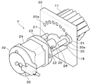
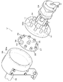
- FIGS. 11 to 14 show an embroidery sewing machine equipped with this type of drilling head.
- the embroidery sewing machine includes two pairs of an embroidery head S and a punching head P for performing punching processing.
- the embroidery head S and the punching head P are adjacent to each other and are provided on the front surface of the upper frame 2 of the embroidery sewing machine body 1.
- the embroidery head S can perform multicolor embroidery by selecting one of a plurality of color threads and performing sewing.
- a pot base 3 having a known hook that performs sewing in cooperation with a needle is disposed on the lower frame 4.
- a receiving base 5 that receives the pons 8 (see FIGS. 12 and 13) is also disposed on the lower frame 4 below each punching head P.
- the punching head P has a structure in which a balance, a thread path and the like are removed from the needle bar case of the well-known embroidery head S.
- the punching head P includes a plurality of needle bars 6 that can be raised and lowered.
- the needle bar 6 selected by the change device 7 (see FIG. 11) installed on the front surface of the upper frame 2 is switched to the use position.
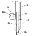
- the needle bar 6 is hollow, and a ponce (piercing tool) 8 is attached to the lower end of each needle bar 6 in place of the sewing needle.
- a lifting bar since a sewing needle is not attached to the needle bar 6 of the punching head P, it is hereinafter referred to as a lifting bar.
- the ponce (piercing tool) 8 includes a through hole 8a penetrating vertically.
- a drilling blade 8b is formed on the inner peripheral edge of the lower end of the through hole 8a.
- a mounting portion 8 c is formed at the upper end of the pounce (piercing tool) 8.
- the attachment portion 8 c is fitted into the lower end of the lifting rod 6, and the screw (piercing tool) 8 is fixed to the lifting rod 6 by tightening the screw 10 of the needle duck 9.
- pons (perforating tools) 8 having different hole shapes and sizes, which can be exchanged.
- a tube 11 for discharging scraps from a through-hole 8a of a ponse (piercing tool) 8 is attached to the upper end of each lifting / lowering rod 6, respectively.
- each tube 11 is supported by a thread stand 12 installed on the upper surface of the upper frame 2.
- Each tube 11 extends upward from the punching head P, extends beyond the upper surface of the thread stand 12 to the back side, and extends downward.
- a manifold block 14 is provided at a position behind the upper surface of the thread stand 13 corresponding to each punching head P.
- the same number of connection ports (not shown) as the lifting rod 6 of the drilling head P are formed on the back side of the manifold block 14.
- Each tube 11 is connected to each connection port.
- a branch hose 15 is connected to the front side opposite to the tube connection port.
- Each branch hose 15 is connected to a hose main pipe 16, and the hose main pipe 16 is connected to a vacuum device 50. Therefore, the scraps generated by the punching process of each punching head P are sucked by the vacuum device 50, and the through hole 8a of the ponse (piercing tool) 8, the hollow portion of the lifting rod 6, the tube 11, the branch hose 15, the hose book The liquid is discharged to the outside through a suction flow path formed from the inside of the pipe 16.
- the perforation device includes a perforation head, a suction device, a suction flow path, and a suction switching device.
- the piercing head includes a plurality of hollow bars that move up and down, and a piercing tool that is provided at the tip of each of the hollow bars and includes a through hole that penetrates in the axial direction.
- the suction device sucks out scraps generated by the punching process of the punching head.
- the suction flow path passes between the through hole provided in the punch and the suction device.
- the suction switching device changes the suction flow path so as to suck only the hollow rod to be perforated among the plurality of hollow rods.
- suction is not performed on a hollow rod that is not subjected to perforation treatment among a plurality of hollow rods. Therefore, the suction force of the suction device can be concentrated on the hollow rod that is subjected to the perforation process. As a result, the airtightness of the suction channel when discharging the scraps by the punching tool can be enhanced, and the suction efficiency by the suction device is improved.
- the suction switching device may include a flow path switching mechanism that switches the suction flow path according to a hollow bar selected from among a plurality of hollow bars.
- a flow path switching mechanism that switches the suction flow path according to a hollow bar selected from among a plurality of hollow bars.
- the suction switching device may further include a contact / separation switching mechanism.
- the contact / separation switching mechanism is located at an intermediate portion of the suction channel switched by the channel switching mechanism.
- the contact / separation switching mechanism switches between the state in which the suction channel is connected to the hollow rod selected by reciprocating in the extending direction of the channel of the suction channel and the separated state. Therefore, the suction flow path is physically switched between connection and separation with respect to the selected hollow rod.
- the flow path switching mechanism switches to a suction flow path corresponding to a selected hollow bar among a plurality of hollow bars in a state where the suction flow path is separated by the contact / separation switching mechanism. Therefore, this configuration can prevent the contact member from being worn and can reduce the load applied to the drive source and the like as compared with the configuration in which switching is performed without separation.
- the flow path switching mechanism may have a connection member and a rotation member.
- the connection member has a plurality of connection ports arranged on an arc.
- the rotation member includes a suction port that communicates with one of the plurality of connection ports by rotating about the center of the arc. Therefore, this configuration can be made more compact than a configuration in which a plurality of connection ports are arranged linearly.
- the flow path switching mechanism is configured to use the rotation shaft of the drive source for switching the suction ports for the plurality of connection ports. Therefore, the flow path switching mechanism can be made compact without adopting a complicated configuration.
- the suction switching device may further include a contact / separation switching mechanism.
- the contact / separation switching mechanism performs switching between connection and separation between each connection port and the suction port by the reciprocating movement of the rotation member along the same axis as the rotation center. Therefore, the contact member provided at the suction port is pressed perpendicularly to the connection port. As a result, the suction port and the connection port are connected without a gap, and airtightness can be maintained. Further, this configuration can prevent the contact member from being worn and can reduce the load applied to the drive source and the like as compared with the configuration in which the suction port and the connection port are switched without being separated.
- the suction switching device may be provided for each of the perforation heads. Therefore, this configuration can flexibly cope with a change in the number of perforation heads and can maintain the suction processing capability.
- FIG. 3 is a plan view of a suction switching device in the perforating apparatus according to Embodiment 1.
- FIG. It is a side view of a suction switching device. It is an enlarged plan view of a suction switching device. It is a top view of the suction switching device in a state where the contact / separation switching means is activated. It is a perspective view of a suction switching device. It is a schematic diagram of the suction switching device in a state where the turning arm of the flow path switching unit is located at the rightmost connection port. It is a schematic diagram of the suction switching device in a state where the turning arm of the flow path switching unit is located at the leftmost connection port.
- FIG. 6 is a side view of a suction switching device in a perforation apparatus according to Embodiment 2.
- FIG. It is a sectional side view of a suction switching device. It is a disassembled perspective view of a suction switching device. It is a front view of the conventional embroidery sewing machine provided with the perforation head. It is a front view of the conventional drilling head. It is a longitudinal cross-sectional view of the raising / lowering rod and ponce (punching tool) of the conventional drilling head. It is a partial top view of the conventional suction channel.
- FIGS. 1 to 10 As an embodiment of the punching device of the present invention, a punching device provided in an embroidery sewing machine will be described.
- the same reference numerals as those shown in FIGS. 11 to 14 are attached to the same configuration as the conventional configuration, and the detailed description may be omitted. .
- the suction switching device V in the punching device is a vacuum device 50 (suction device), the hose main pipe 16 connected to the vacuum device 50, and the piping of the branch hose 15 are shown as conventional configurations. Same as 11-14.
- Each branch hose 15 branched from the hose main pipe 16 is connected to a connection block 17 corresponding to each perforation head P (see FIG. 12).
- a connection port to which the branch hose 15 is connected is provided on one surface (surface) of the connection block 17.
- a small-diameter connection port is provided on the opposite surface (back surface) of the connection block 17.
- a tube 18 connected to the suction switching device V is connected to a small-diameter connection port (not shown).
- each thread spool 19 wound with an upper thread to be supplied to the sewing needle of the embroidery head S is placed in the front region of the thread stand 13.
- the suction switching device V is disposed behind each connection block 17 with a predetermined interval.
- the suction switching device V includes a flow path switching unit (flow path switching mechanism) and a contact / separation switching unit (contact / separation switching mechanism).
- Flow path switching means (flow path switching mechanism)
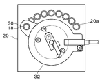
- a plate-like support plate 20 (connection member) is erected on the thread stand 13.
- the support plate 20 is fixed to the thread stand 13 with bolts 21 inserted into the thread stand 13 from below the thread stand 13.
- the support plate 20 (connection member) is provided with the same number of connection ports 20 a penetrating in the thickness direction as the ponce 8 (elevating bar 6) shown in FIG. 12.
- the connection port 20a is arranged in an arc shape with a certain interval. Tubes 11 connected to the upper ends of the lifting rods 6 of the perforation head P shown in FIG. 12 are connected to the back surfaces of the connection ports 20a of the support plate 20 shown in FIG.
- connection position of the tube 11 with respect to the support plate 20 is the same as the arrangement order of the ponses 8 (elevating bars 6) of the drilling head P shown in FIG. That is, the tube 11 connected to the rightmost lifting bar 6 of the punching head P is connected to the connection port 20a (see FIG. 5) located on the rightmost side of the support plate 20 (see FIG. 5) in a front view.
- the tube 11 connected to the leftmost lifting bar 6 of the drilling head P is connected to the connection port 20 a located on the leftmost side of the support plate 20.
- a stud 22 is erected on the front side of the support plate 20, and a mounting plate 23 is attached to the tip of the stud 22.
- the mounting plate 23 is provided with a shaft hole (not shown) through which the motor shaft is inserted.
- the motor shaft passes through the mounting plate 23 and protrudes from the mounting plate 23 toward the support plate 20.
- a rotating body 25 is fixed to the outer periphery of the motor shaft.
- the rotating body 25 integrally includes a cylindrical base portion 25a and a guide portion 25b having a smaller diameter than the base portion 25a.
- a pin 26 is provided through the tip of the guide portion 25b.
- a moving body 27 is fitted on the outer periphery of the guide portion 25b.
- the moving body 27 has a cylindrical shape configured to slide in the axial direction along the outer peripheral surface of the guide portion 25b of the rotating body 25.
- the moving body 27 includes a guide groove 28 with which the pin 26 of the guide portion 25b is engaged.
- the guide groove 28 extends in parallel with the motor shaft.
- the pin 26 protrudes from the guide groove 28 in the radial direction. Therefore, the movable body 27 is restricted to be non-rotatable by the pin 26 engaged with the guide groove 28 and moves linearly (advances and retreats) in the axial direction, and is pushed by the pin 26 and rotates integrally with the rotary body 25.
- a rotating arm 30 (rotating member) is fixed to the moving body 27 by a connector 29.
- the base of the rotating arm 30 is pivotally supported at the center of the moving body 27.
- a suction port 30 a is provided on the end side of the rotating arm 30.
- the suction port 30a moves so as to face the plurality of connection ports 20a provided in the support plate 20 in order as the rotating arm 30 rotates.
- the tube 18 from the connection block 17 is connected to the suction port 30a, and a ring-shaped contact member 31 made of sponge rubber is provided on the opposite surface of the suction port 30a.
- a detector 33 for detecting the reference position (origin) of the rotating arm 30 is provided on the other surface side of the motor 24 via the mounting plate 32.
- suction switching device V When a punching process is performed on a leather sheet that is a workpiece, the vacuum device 50 is operated in advance in order to collect scraps from the punching process. Then, as is well known, a perforating process is performed on the leather sheet by the perforating head P while moving the holding frame holding the leather sheet in the X and Y directions on the table top according to the perforated pattern data. In the course of the drilling process, the suction switching device operates as follows.
- FIG. 6 shows the position of the rotating arm 30 when the punching process is performed using the ponce 8 positioned on the rightmost side of the punching head P.
- the rotating arm 30 moves with respect to the support plate 20 by the operation of the motor 24 which is one configuration of the flow path switching unit.
- the rotating arm 30 is aligned with the connection port 20a to which the tube 11 of the ponce 8 (lifting rod 6) located on the rightmost side of the drilling head P is connected.
- the contact member 31 of the rotating arm 30 is pressed vertically against the connection port 20a by the operation of the air cylinder 34 which is one configuration of the contact / separation switching means (connection position 30X). .
- the tube 18 from the connection block 17 to which the branch hose 15 is connected and the tube 11 connected to the ponce 8 (lifting rod 6) are connected without a gap. For this reason, only the ponce 8 (lifting rod 6) located on the rightmost side of the drilling head P is sucked by the vacuum device 50 while keeping the airtightness of the flow path.
- FIG. 7 shows the position of the rotating arm 30 when the pierce 8 to be punched is switched to the ponce 8 positioned on the leftmost side of the punching head P.
- the air cylinder 34 operates, and the position of the rotating arm 30 moves from the retracted position 30Y to the connection position 30X. Thereby, the contact member 31 of the rotation arm 30 is pressed against the connection port 20a. Thus, the tube 18 from the connection block 17 to which the branch hose 15 is connected and the tube 11 connected to the ponce 8 (elevating bar 6) are connected. Then, the suction channel is switched so as to be connected to the ponce 8 (lifting rod 6) located on the leftmost side of the punching head P. Note that the operation of the suction switching device V (switching of the suction flow path) is synchronized with the switching of the pons 8 (elevating bar 6) to be used. When the pons 8 (elevating bar 6) to be used is switched based on the perforated pattern data, the suction flow path is also switched to automatically connect to the pons 8 (elevating bar 6).
- the suction switching device V connects the suction path connected to the vacuum device 50 only to the ponce 8 (elevating rod 6) that performs the perforating process, and performs suction. Due to this structure, the airtightness of the flow path is higher than in the prior art, and the scraps can be efficiently sucked by the vacuum device 50.
- the suction switching device V ′ in the second embodiment includes a cylindrical manifold 36 (connection member) having a hollow portion 36a therein.
- a branch hose 15 connected to the hose main pipe 16 of the vacuum device 50 shown in FIG. 1 is connected to one side surface of the manifold 36.
- a connection port 36 b that penetrates the inside of the manifold 36 is provided on the opposite surface of the manifold 36.
- the number of connection ports 36b is the same as the number of ponses 8 (elevating bars 6) of the drilling head P.
- the connection ports 36b are annularly arranged with a certain interval.
- connection port 36b A channel switching means and a contact / separation switching means are provided on the annular central axis in which the connection port 36b is provided.
- a rotating plate 37 is provided as a member corresponding to the rotating arm 30 in the first embodiment. The rotating plate 37 (rotating member) is housed in the hollow portion 36a of the manifold 36, and is connected to the tip of the rod 35 of the air cylinder 34 which is one configuration of the contact / separation switching means.
- the rotating plate 37 includes one contact member 38 and a plurality of sealing members 39, and is concentric with the same diameter as the circular shape in which the connection port 36b is disposed. Are arranged at the same interval.
- the contact member 38 has a ring shape made of sponge rubber.
- the rotary plate 37 is provided with a suction port 40 that penetrates in the thickness direction only at a position where the contact member 38 is attached.
- the sealing member 39 has a shape having a suction portion at the tip made of rubber, and is screwed to the rotary plate 37. It functions as a lid for closing each connection port 36b of the pons 8 (elevating bar 6) other than the pons 8 (elevating bar 6) to be subjected to the perforating process.
- the suction switching device V ′ of the second embodiment rotates the rotating plate 37 by the motor 24 that is one component of the flow path switching means, as in the first embodiment.
- the position of the rotary plate 37 is switched so that the contact member 38 having a suction port corresponds to the connection port 36b of the ponce 8 (elevating rod 6) that performs the perforating process.
- the air cylinder 34 which is one component of the contact / separation switching means, is operated, and the position of the rotating plate 37 is moved from the retracted position 37Y to the connected position (not shown).
- the punching apparatus of Embodiments 1 and 2 has the following effects.
- the punching device includes suction switching devices V and V ′ for sucking only the lifting rod 6 that performs the punching processing among the plurality of lifting rods 6 (hollow rods).
- suction is not performed in the raising / lowering rod 6 which does not perforate among the several raising / lowering rods 6, suction is not performed. Therefore, the suction force of the vacuum device 50 (suction device) can be concentrated on the elevating rod 6 that performs the drilling process. As a result, the airtightness of the flow path for discharging the scraps is improved, and the suction efficiency for sucking the scraps of the vacuum device 50 is improved.
- suction switching devices V, V ′ have flow path switching means for switching the flow path according to the lifting bar 6 selected from the plurality of lifting bars 6. Thereby, only the flow path corresponding to the raising / lowering rod 6 which perforates among the several raising / lowering rods 6 can be attracted
- suction switching devices V and V ′ have contact / separation switching means for switching connection and separation at an intermediate portion of the suction flow path switched by the flow path switching means. Accordingly, the suction channel is physically switched between connection and separation with respect to the selected lifting rod 6 by the channel switching means.
- the flow path switching means selects the suction flow path corresponding to the selected lift bar 6 among the plurality of lift bars 6 (hollow bars). Switch the road. Since it is this structure, compared with the structure switched without isolate
- the flow path switching means has a plurality of connection ports 20a and 36b arranged on an arc.
- the plurality of connection ports 20a and 36b can be configured more compactly than the configuration in which the connection ports 20a and 36b are arranged linearly.
- the flow path switching means uses the rotating shaft of the motor 24 (drive source) for switching the suction ports 30a, 40 to the plurality of connection ports 20a, 36b. Because of this configuration, the flow path switching means can be made compact without adopting a complicated configuration for the flow path switching means.
- connection and separation between the plurality of connection ports 20a and 36b and the suction ports 30a and 40 is performed by reciprocating the rotation arm 30 and the rotation plate 37 of the contact / separation switching unit along the same axis as the rotation center. I do. Thereby, the contact member provided in the suction ports 30a and 40 is pressed perpendicularly to the connection ports 20a and 36b. Therefore, the suction port and the connection port are connected without a gap, and airtightness can be maintained.
- the suction switching devices V and V ′ are provided for each perforation head P. Therefore, even if the number of punching heads P increases, the suction switching devices V and V ′ can be provided for each punching head P. Thus, this configuration can flexibly cope with a change in the number of perforation heads P and can also maintain the suction processing capability.
- the punching apparatus of this invention is not limited to this embodiment, It can implement with other various forms.
- the embodiment includes two pairs of the embroidery head S and the punching head P.
- the punching apparatus includes a plurality of embroidery machines configured by two or more pairs and only the punching heads P.
- it may be a punching device provided with only one punching head P.
Abstract
Description
実施形態1に係る穿孔装置における吸引切替装置Vは、図1に示すとおり、バキューム装置50(吸引装置)、バキューム装置50に繋がるホース本管16、分岐ホース15の配管は従来構成として示した図11~14と同様である。ホース本管16から分岐された各分岐ホース15は各穿孔ヘッドP(図12参照)に対応する接続ブロック17に接続されている。接続ブロック17の一面(表面)に分岐ホース15が接続される接続口が設けられる。接続ブロック17の反対面(裏面)に小径の接続口が設けられる。小径の接続口(図示外)に吸引切替装置Vに繋がるチューブ18が接続されている。糸立て皿13の前領域には、刺繍ヘッドSの縫い針に供給される上糸を巻いた各糸駒19が載置されている。吸引切替装置Vは、各接続ブロック17の後方に所定の間隔を空けて配置されている。吸引切替装置Vは、流路切替手段(流路切替機構)と接離切替手段(接離切替機構)で構成されている。
図2に示すとおり、板状の支持プレート20(接続部材)が糸立て皿13上に立設される。支持プレート20は、糸立て皿13の下方から糸立て皿13に挿入されたボルト21で糸立て皿13に固定されている。図5に示すように、支持プレート20(接続部材)には、厚み方向に貫通する接続口20aが図12に示すポンス8(昇降棒6)と同数設けられている。接続口20aは、一定の間隔を空けて円弧状に配設されている。図12に示す穿孔ヘッドPの各昇降棒6の上端に接続されているチューブ11が図5に示す支持プレート20の各接続口20aの背面部に接続されている。支持プレート20に対するチューブ11の接続位置は図11に示す穿孔ヘッドPのポンス8(昇降棒6)の並び順と同じである。すなわち穿孔ヘッドPの最も右側の昇降棒6に接続されたチューブ11が、正面視において支持プレート20(図5参照)の最も右に位置する接続口20a(図5参照)に接続される。穿孔ヘッドPの最も左側の昇降棒6に接続されたチューブ11が、支持プレート20の最も左に位置する接続口20aに接続される。
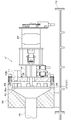
図3,4に示すように支持プレート20の背面側には、エアシリンダ34が取り付けられている。エアシリンダ34のロッド35が支持プレート20を貫通してモータ24に向けて前方に突出している。ロッド35の軸心はモータ軸の軸心と同一線上である。ロッド35の先端は、回動アーム30を移動体27に固定している連結具29に連結されている。したがって、エアシリンダ34を駆動してロッド35を進退させると、移動体27が回転体25のガイド部25bに沿ってスライド移動する。これにより回動アーム30の位置が接続位置30Xと退避位置30Yへと切り替わる。具体的には、図3に示すとおり、エアシリンダ34のロッド35が後退すると、回動アーム30が支持プレート20方向(後方)に移動する。これにより回動アーム30の当接部材31が支持プレート20に設けられている接続口20aに押し当てられる(接続位置30X)。一方、図4に示すとおり、エアシリンダ34のロッド35が進出すると、回動アーム30がモータ24方向(前方)に移動する。これにより回動アーム30の当接部材31が接続口20aから切り離される(退避位置30Y)。
被加工物である皮革シートに穿孔処理を施す場合は、あらかじめ、穿孔処理による抜き屑を回収するためにバキューム装置50を作動させておく。そして、周知のとおり、穿孔柄データにしたがって皮革シートを保持した保持枠をテーブル上面でX、Y方向に移動させながら、穿孔ヘッドPにより穿孔処理を皮革シートに施す。穿孔処理の過程において、吸引切替装置は以下のように作動する。
図8~10に示すとおり、実施形態2における吸引切替装置V’は、内部に空洞部36aを有する円筒状のマニホールド36(接続部材)を備えている。マニホールド36の片側面に図1に示すバキューム装置50のホース本管16に繋がる分岐ホース15が接続されている。マニホールド36の反対面には、マニホールド36の内部と貫通する接続口36bが設けられている。接続口36bの数は穿孔ヘッドPのポンス8(昇降棒6)と同数である。接続口36bは一定の間隔を空けて環状に配設されている。そして、穿孔ヘッドP(図12参照)の各昇降棒6の上端に接続されているチューブ11は、この接続口36bにそれぞれ接続されている。接続口36bが配設された環状の中心軸上に、流路切替手段と接離切替手段が設けられている。また、実施形態1における回動アーム30に相当する部材として回転プレート37(回動部材)が設けられている。回転プレート37(回動部材)はマニホールド36の空洞部36aに収納され、接離切替手段の一構成であるエアシリンダ34のロッド35の先端に連結されている。
Claims (7)
- 穿孔装置であって、
上下動する複数の中空棒と、該中空棒の先端にそれぞれ設けられ軸方向に貫通する貫通孔を備えた穿孔具と、を含む穿孔ヘッドと、
前記穿孔ヘッドの穿孔処理による抜き屑を吸引する吸引装置と、
前記穿孔具に設けられた貫通孔と前記吸引装置の間を通じる吸引流路と、
前記複数の中空棒のうち穿孔処理を施す中空棒のみを吸引するように前記吸引流路を変更する吸引切替装置と、を有する穿孔装置。 - 請求項1に記載の穿孔装置であって、
前記吸引切替装置は、前記複数の中空棒のうち選択された中空棒に応じて吸引流路を切り替える流路切替機構を有する穿孔装置。 - 請求項2に記載の穿孔装置であって、
前記吸引切替装置は、前記流路切替機構によって切り替えられた吸引流路の中間部位において前記吸引流路の流路の延出方向に往復移動することで選択された前記中空棒に対して前記吸引流路が接続された状態と分離した状態とに切り替える接離切替機構を有する穿孔装置。 - 請求項3に記載の穿孔装置であって、
前記流路切替機構は、前記接離切替機構による吸引流路の分離を行った状態において、前記複数の中空棒のうち選択された中空棒に応ずる吸引流路に切り替える穿孔装置。 - 請求項2から請求項4のいずれか1つに記載の穿孔装置であって、
前記流路切替機構は、
円弧上に配された複数の接続口が設けられた接続部材と、該円弧の中心を回動中心として回動することで前記複数の接続口のうち一つの接続口と連通する吸引口を備えた回動部材を有する穿孔装置。 - 請求項2~5のいずれか1つに記載の穿孔装置であって、
前記流路切替機構は、
円弧上に配された複数の接続口が設けられた接続部材と、該円弧の中心を回動中心として回動することで前記複数の接続口のうち一つの接続口と連通する吸引口を備えた回動部材を有し、
前記吸引切替装置は、前記回動部材がその回動中心と同軸上に沿って往復移動することで、前記各接続口と前記吸引口との接続と分離の切り替えを行う接離切替機構を有する穿孔装置。 - 請求項1から請求項6のいずれか1つに記載の穿孔装置であって、
前記吸引切替装置は、前記穿孔ヘッド毎に設けられている穿孔装置。
Priority Applications (5)
| Application Number | Priority Date | Filing Date | Title |
|---|---|---|---|
| US16/607,811 US11511452B2 (en) | 2017-04-25 | 2018-04-18 | Punching device |
| CN201880027176.2A CN110651079B (zh) | 2017-04-25 | 2018-04-18 | 穿孔装置 |
| JP2019514423A JP7013036B2 (ja) | 2017-04-25 | 2018-04-18 | 穿孔装置 |
| KR1020197033425A KR102427391B1 (ko) | 2017-04-25 | 2018-04-18 | 천공 장치 |
| EP18790828.0A EP3617361B1 (en) | 2017-04-25 | 2018-04-18 | Punching device |
Applications Claiming Priority (2)
| Application Number | Priority Date | Filing Date | Title |
|---|---|---|---|
| JP2017085848 | 2017-04-25 | ||
| JP2017-085848 | 2017-04-25 |
Publications (1)
| Publication Number | Publication Date |
|---|---|
| WO2018198900A1 true WO2018198900A1 (ja) | 2018-11-01 |
Family
ID=63919216
Family Applications (1)
| Application Number | Title | Priority Date | Filing Date |
|---|---|---|---|
| PCT/JP2018/015976 WO2018198900A1 (ja) | 2017-04-25 | 2018-04-18 | 穿孔装置 |
Country Status (6)
| Country | Link |
|---|---|
| US (1) | US11511452B2 (ja) |
| EP (1) | EP3617361B1 (ja) |
| JP (1) | JP7013036B2 (ja) |
| KR (1) | KR102427391B1 (ja) |
| CN (1) | CN110651079B (ja) |
| WO (1) | WO2018198900A1 (ja) |
Citations (5)
| Publication number | Priority date | Publication date | Assignee | Title |
|---|---|---|---|---|
| JPH0530759A (ja) * | 1991-07-19 | 1993-02-05 | Fuji Electric Co Ltd | 断続通電用mos回路 |
| JPH09234698A (ja) * | 1995-12-25 | 1997-09-09 | Ngk Insulators Ltd | シート材の順送り加工方法 |
| JP2000108095A (ja) * | 1998-10-05 | 2000-04-18 | Fujimori Kogyo Co Ltd | 穿孔装置 |
| WO2015076389A1 (ja) | 2013-11-25 | 2015-05-28 | 東海工業ミシン株式会社 | 穿孔ヘッドを備えた刺繍ミシン |
| JP2018024089A (ja) * | 2016-08-12 | 2018-02-15 | サンスター カンパニー,リミテッド | パンチング機に適用されるサクション装置 |
Family Cites Families (23)
| Publication number | Priority date | Publication date | Assignee | Title |
|---|---|---|---|---|
| US2646095A (en) * | 1949-03-24 | 1953-07-21 | Robert Legg Ltd | Machine for cutting tobacco and the like |
| US3194095A (en) * | 1962-12-31 | 1965-07-13 | Lloyd P Buck | Punch confett remover |
| NL7002316A (ja) * | 1970-02-19 | 1971-08-23 | ||
| DE2062745C2 (de) * | 1970-12-19 | 1983-10-27 | Ramisch Kleinewefers Gmbh, 4150 Krefeld | Verfahren zum Ausstechen von Teigfiguren, beispielsweise Brezeln, aus einem Teigband |
| DE3420763A1 (de) | 1984-06-04 | 1985-12-05 | Rudolf 5450 Neuwied Reich | Verfahren und vorrichtung zum wahlweisen besticken und/oder gravieren und/oder bemalen und/oder perforieren von materialbahnen bzw. zuschnitten aus fuer nadel und bohrer durchlaessigen oder undurchlaessigen materialien |
| US4599926A (en) * | 1984-07-16 | 1986-07-15 | Preston Engravers, Inc. | Rotary cutting dies with vacuum assist to cut and clear waste |
| DE3629968A1 (de) * | 1986-09-03 | 1988-03-10 | Messerschmitt Boelkow Blohm | Vorrichtung zum aufnehmen und ablegen von zuschnitten |
| US5778806A (en) | 1990-12-26 | 1998-07-14 | Ralph's Industrial Sewing Machine Company | Sewing and material removal assembly |
| JP2721947B2 (ja) | 1993-06-17 | 1998-03-04 | 極東産機株式会社 | 麺茹で装置 |
| JPH07157117A (ja) * | 1993-12-08 | 1995-06-20 | Fuji Photo Film Co Ltd | 板状体または箱体の真空チャック装置 |
| JP2736602B2 (ja) | 1994-01-10 | 1998-04-02 | 徳男 高橋 | 刺しゅう部へのかがり穴の形成方法 |
| DE69529350T2 (de) * | 1994-04-13 | 2003-10-16 | Winkler & Duennebier Ag | Zylinder zur Befestigung eines biegsamen Stanzwerkzeuges |
| US5906702A (en) * | 1995-02-07 | 1999-05-25 | Precision Dynamics Corporation | Method and apparatus for removing profiles |
| US5836226A (en) | 1995-12-25 | 1998-11-17 | Ngk Insulators, Ltd. | Apparatus for progressively feeding and machining sheet material |
| DE10153784B4 (de) * | 2001-04-12 | 2005-02-03 | Trumpf Sachsen Gmbh | Modulares Steuersystem für eine Ladevorrichtung mit gezielter Sauggreifersteuerung |
| CH695854A5 (fr) * | 2002-09-12 | 2006-09-29 | Bobst Sa | Procédé et dispositif de séparation de poses dans une machine de découpe d'éléments en plaque. |
| JP4862907B2 (ja) * | 2009-03-24 | 2012-01-25 | ブラザー工業株式会社 | 多針式ミシン |
| JP5779450B2 (ja) * | 2011-08-24 | 2015-09-16 | 株式会社島精機製作所 | 目打ち装置を備える裁断機、およびその目打ち屑除去方法 |
| CN106133227B (zh) * | 2014-03-27 | 2018-11-30 | 东海工业缝纫机株式会社 | 能够缝合帘线材料的刺绣缝纫机 |
| JP6448997B2 (ja) * | 2014-11-26 | 2019-01-09 | 蛇の目ミシン工業株式会社 | ミシンの糸通し装置 |
| US9988221B2 (en) * | 2014-12-11 | 2018-06-05 | Translogic Corporation | Carrier brake for pneumatic transport system |
| US10814498B2 (en) * | 2017-11-07 | 2020-10-27 | Berkshire Grey, Inc. | Systems and methods for providing dynamic vacuum pressure at an end effector using a single vacuum source |
| DE102019110913A1 (de) * | 2019-04-26 | 2020-10-29 | J. Schmalz Gmbh | Flächensauggreifer |
-
2018
- 2018-04-18 CN CN201880027176.2A patent/CN110651079B/zh active Active
- 2018-04-18 EP EP18790828.0A patent/EP3617361B1/en active Active
- 2018-04-18 KR KR1020197033425A patent/KR102427391B1/ko active IP Right Grant
- 2018-04-18 US US16/607,811 patent/US11511452B2/en active Active
- 2018-04-18 JP JP2019514423A patent/JP7013036B2/ja active Active
- 2018-04-18 WO PCT/JP2018/015976 patent/WO2018198900A1/ja unknown
Patent Citations (5)
| Publication number | Priority date | Publication date | Assignee | Title |
|---|---|---|---|---|
| JPH0530759A (ja) * | 1991-07-19 | 1993-02-05 | Fuji Electric Co Ltd | 断続通電用mos回路 |
| JPH09234698A (ja) * | 1995-12-25 | 1997-09-09 | Ngk Insulators Ltd | シート材の順送り加工方法 |
| JP2000108095A (ja) * | 1998-10-05 | 2000-04-18 | Fujimori Kogyo Co Ltd | 穿孔装置 |
| WO2015076389A1 (ja) | 2013-11-25 | 2015-05-28 | 東海工業ミシン株式会社 | 穿孔ヘッドを備えた刺繍ミシン |
| JP2018024089A (ja) * | 2016-08-12 | 2018-02-15 | サンスター カンパニー,リミテッド | パンチング機に適用されるサクション装置 |
Non-Patent Citations (1)
| Title |
|---|
| See also references of EP3617361A4 |
Also Published As
| Publication number | Publication date |
|---|---|
| EP3617361B1 (en) | 2021-11-24 |
| EP3617361A4 (en) | 2021-01-13 |
| US20200130217A1 (en) | 2020-04-30 |
| CN110651079A (zh) | 2020-01-03 |
| KR20190139265A (ko) | 2019-12-17 |
| CN110651079B (zh) | 2021-12-21 |
| JP7013036B2 (ja) | 2022-01-31 |
| US11511452B2 (en) | 2022-11-29 |
| KR102427391B1 (ko) | 2022-08-01 |
| JPWO2018198900A1 (ja) | 2020-02-27 |
| EP3617361A1 (en) | 2020-03-04 |
Similar Documents
| Publication | Publication Date | Title |
|---|---|---|
| KR101117567B1 (ko) | 가공기계의 피가공물 장착용 지그 | |
| WO2018101014A1 (ja) | 穿孔装置及びその穿孔装置を備えた刺繍ミシン | |
| CN110370373B (zh) | 一种会计凭证钻孔机 | |
| JPH06304367A (ja) | 加工布保持装置 | |
| JP4362449B2 (ja) | ボタン穴ミシン | |
| WO2018198900A1 (ja) | 穿孔装置 | |
| JP2005138263A (ja) | ブッシュ圧入装置 | |
| KR100346978B1 (ko) | 금속판재 가공장치 | |
| CN105689508A (zh) | 自动输送式多孔冲压装置 | |
| KR200188901Y1 (ko) | 금속판재 가공장치 | |
| JP6550619B2 (ja) | 溶接ボルトの供給装置 | |
| JP6042507B1 (ja) | ボタン穴かがりミシンの挟持機構 | |
| JP5193887B2 (ja) | パンチプレス | |
| CN111001851A (zh) | 一种用于拆线剪加工的连续打孔机构 | |
| CN212955668U (zh) | 一种冲绣一体式绣花机 | |
| CN210765848U (zh) | 刺绣布料快速夹紧装置及电脑绣花机 | |
| JP2017056477A (ja) | レーザノズル交換方法及びレーザ加工機 | |
| CN211304925U (zh) | Pcb铜板分板机 | |
| JP4221377B2 (ja) | ボタン穴ミシン | |
| CN219254806U (zh) | 定位夹紧装置和具有它的环锭细纱机罗拉座多工位打孔机 | |
| JPH10118994A (ja) | 穿孔装置におけるワークに付されたマークの芯出し装置 | |
| CN214161459U (zh) | 活塞顶部钻孔装置 | |
| CN212121727U (zh) | 一种用于拆线剪加工的连续打孔机构 | |
| JP2018011846A (ja) | ミシン | |
| JPH0715753Y2 (ja) | 試験片作成装置 |
Legal Events
| Date | Code | Title | Description |
|---|---|---|---|
| 121 | Ep: the epo has been informed by wipo that ep was designated in this application |
Ref document number: 18790828 Country of ref document: EP Kind code of ref document: A1 |
|
| ENP | Entry into the national phase |
Ref document number: 2019514423 Country of ref document: JP Kind code of ref document: A |
|
| NENP | Non-entry into the national phase |
Ref country code: DE |
|
| ENP | Entry into the national phase |
Ref document number: 20197033425 Country of ref document: KR Kind code of ref document: A |
|
| ENP | Entry into the national phase |
Ref document number: 2018790828 Country of ref document: EP Effective date: 20191125 |