WO2018198900A1 - Punching device - Google Patents

Punching device Download PDF

Info

Publication number
WO2018198900A1
WO2018198900A1 PCT/JP2018/015976 JP2018015976W WO2018198900A1 WO 2018198900 A1 WO2018198900 A1 WO 2018198900A1 JP 2018015976 W JP2018015976 W JP 2018015976W WO 2018198900 A1 WO2018198900 A1 WO 2018198900A1
Authority
WO
WIPO (PCT)
Prior art keywords
suction
flow path
punching
hollow
switching
Prior art date
Application number
PCT/JP2018/015976
Other languages
French (fr)
Japanese (ja)
Inventor
勝治 吉川
Original Assignee
東海工業ミシン株式会社
Priority date (The priority date is an assumption and is not a legal conclusion. Google has not performed a legal analysis and makes no representation as to the accuracy of the date listed.)
Filing date
Publication date
Application filed by 東海工業ミシン株式会社 filed Critical 東海工業ミシン株式会社
Priority to US16/607,811 priority Critical patent/US11511452B2/en
Priority to CN201880027176.2A priority patent/CN110651079B/en
Priority to JP2019514423A priority patent/JP7013036B2/en
Priority to KR1020197033425A priority patent/KR102427391B1/en
Priority to EP18790828.0A priority patent/EP3617361B1/en
Publication of WO2018198900A1 publication Critical patent/WO2018198900A1/en

Links

Images

Classifications

    • BPERFORMING OPERATIONS; TRANSPORTING
    • B26HAND CUTTING TOOLS; CUTTING; SEVERING
    • B26DCUTTING; DETAILS COMMON TO MACHINES FOR PERFORATING, PUNCHING, CUTTING-OUT, STAMPING-OUT OR SEVERING
    • B26D7/00Details of apparatus for cutting, cutting-out, stamping-out, punching, perforating, or severing by means other than cutting
    • B26D7/18Means for removing cut-out material or waste
    • B26D7/1845Means for removing cut-out material or waste by non mechanical means
    • B26D7/1863Means for removing cut-out material or waste by non mechanical means by suction
    • BPERFORMING OPERATIONS; TRANSPORTING
    • B26HAND CUTTING TOOLS; CUTTING; SEVERING
    • B26DCUTTING; DETAILS COMMON TO MACHINES FOR PERFORATING, PUNCHING, CUTTING-OUT, STAMPING-OUT OR SEVERING
    • B26D7/00Details of apparatus for cutting, cutting-out, stamping-out, punching, perforating, or severing by means other than cutting
    • B26D7/18Means for removing cut-out material or waste
    • BPERFORMING OPERATIONS; TRANSPORTING
    • B26HAND CUTTING TOOLS; CUTTING; SEVERING
    • B26FPERFORATING; PUNCHING; CUTTING-OUT; STAMPING-OUT; SEVERING BY MEANS OTHER THAN CUTTING
    • B26F1/00Perforating; Punching; Cutting-out; Stamping-out; Apparatus therefor
    • B26F1/02Perforating by punching, e.g. with relatively-reciprocating punch and bed
    • B26F1/04Perforating by punching, e.g. with relatively-reciprocating punch and bed with selectively-operable punches
    • DTEXTILES; PAPER
    • D05SEWING; EMBROIDERING; TUFTING
    • D05BSEWING
    • D05B37/00Devices incorporated in sewing machines for slitting, grooving, or cutting
    • DTEXTILES; PAPER
    • D05SEWING; EMBROIDERING; TUFTING
    • D05CEMBROIDERING; TUFTING
    • D05C7/00Special-purpose or automatic embroidering machines
    • D05C7/04Special-purpose or automatic embroidering machines for boring or jogging
    • DTEXTILES; PAPER
    • D05SEWING; EMBROIDERING; TUFTING
    • D05DINDEXING SCHEME ASSOCIATED WITH SUBCLASSES D05B AND D05C, RELATING TO SEWING, EMBROIDERING AND TUFTING
    • D05D2305/00Operations on the work before or after sewing
    • D05D2305/50Removing cut-out material or waste

Abstract

This punching device is provided with: a punching head; a vacuum apparatus (50); a suction flow passage; and a suction switching apparatus (V). The punching head includes: a plurality of hollow rods that move vertically; and punching tools respectively provided on the tips of the hollow rods and having through-holes penetrating in the axial direction. The vacuum apparatus (50) suctions punched scraps that are produced by a punching processing of the punching head. The suction flow passage connects the through-holes of the punching tools and the vacuum device (50). The suction switching apparatus (V) changes the path of the suction flow passage so that the suction flow passage communicates only with a hollow rod, which performs the punching processing, among the plurality of hollow rods.

Description

穿孔装置Drilling device
 本発明は、穿孔装置に関する。 The present invention relates to a perforating apparatus.
 被加工物に刺繍や穿孔処理を施す刺繍ミシンが知られている。例えば国際公開第2015/076389号に開示された刺繍ミシンは、複数本の針を備えた刺繍ヘッドと、複数本のポンスを備えた穿孔ヘッドと、枠を有する。刺繍ヘッドと穿孔ヘッドは、間隔を空けて並設される。枠は、ミシンテーブル上で皮革シートなどの被加工物を保持する。枠は、刺繍時および穿孔処理時に前後左右に移動される。 Embroidery sewing machines that perform embroidery and perforation on workpieces are known. For example, an embroidery sewing machine disclosed in International Publication No. 2015/076389 has an embroidery head having a plurality of needles, a drilling head having a plurality of ponses, and a frame. The embroidery head and the drilling head are arranged side by side with a space therebetween. The frame holds a workpiece such as a leather sheet on the sewing table. The frame is moved back and forth and left and right during embroidery and perforation processing.
 図11~14に、この種の穿孔ヘッドを備えた刺繍ミシンを示す。図11に示すように刺繍ミシンは、刺繍ヘッドSと穿孔処理を施すための穿孔ヘッドPとからなるペアを2つ備えている。刺繍ヘッドSと穿孔ヘッドPは、隣接しており、刺繍ミシン本体1の上フレーム2の前面に設けられる。刺繍ヘッドSは、複数の色糸のいずれかを選択して縫いを行うことにより多色刺繍が可能である。各刺繍ヘッドSの下方には、針と協働して縫いを行う周知の釜を備えた釜土台3が下フレーム4上に配置されている。また、各穿孔ヘッドPの下方には、ポンス(穿孔具)8(図12、13参照)を受け止める受け土台5が同じく下フレーム4上に配置されている。 FIGS. 11 to 14 show an embroidery sewing machine equipped with this type of drilling head. As shown in FIG. 11, the embroidery sewing machine includes two pairs of an embroidery head S and a punching head P for performing punching processing. The embroidery head S and the punching head P are adjacent to each other and are provided on the front surface of the upper frame 2 of the embroidery sewing machine body 1. The embroidery head S can perform multicolor embroidery by selecting one of a plurality of color threads and performing sewing. Below each embroidery head S, a pot base 3 having a known hook that performs sewing in cooperation with a needle is disposed on the lower frame 4. A receiving base 5 that receives the pons 8 (see FIGS. 12 and 13) is also disposed on the lower frame 4 below each punching head P.
 穿孔ヘッドPは、図12に示すとおり、周知の刺繍ヘッドSの針棒ケースにおいて天秤や糸道などを取り除いた構造である。穿孔ヘッドPは、刺繍ヘッドSと同様に、昇降可能な複数の針棒6を具備している。上フレーム2の前面に設置されたチェンジ装置7(図11参照)により選択された針棒6が使用位置に切り替えられる。針棒6は中空であり、各針棒6の下端には、縫い針に替えてポンス(穿孔具)8がそれぞれ取り付けられている。なお、穿孔ヘッドPの針棒6には縫い針が取り付けられていないので、以下、昇降棒と称する。 As shown in FIG. 12, the punching head P has a structure in which a balance, a thread path and the like are removed from the needle bar case of the well-known embroidery head S. As with the embroidery head S, the punching head P includes a plurality of needle bars 6 that can be raised and lowered. The needle bar 6 selected by the change device 7 (see FIG. 11) installed on the front surface of the upper frame 2 is switched to the use position. The needle bar 6 is hollow, and a ponce (piercing tool) 8 is attached to the lower end of each needle bar 6 in place of the sewing needle. In addition, since a sewing needle is not attached to the needle bar 6 of the punching head P, it is hereinafter referred to as a lifting bar.
 ポンス(穿孔具)8は、図13に示すとおり、上下に貫通する貫通孔8aを備えている。貫通孔8aの下端の内周縁に穿孔刃8bが形成されている。ポンス(穿孔具)8の上端には取付部8cが形成されている。取付部8cを昇降棒6の下端に嵌入し、針ダキ9のネジ10を締め付けることでポンス(穿孔具)8が昇降棒6に固定される。ポンス(穿孔具)8には孔形状や大きさが異なる種々のものがあり、交換可能である。 As shown in FIG. 13, the ponce (piercing tool) 8 includes a through hole 8a penetrating vertically. A drilling blade 8b is formed on the inner peripheral edge of the lower end of the through hole 8a. A mounting portion 8 c is formed at the upper end of the pounce (piercing tool) 8. The attachment portion 8 c is fitted into the lower end of the lifting rod 6, and the screw (piercing tool) 8 is fixed to the lifting rod 6 by tightening the screw 10 of the needle duck 9. There are various types of pons (perforating tools) 8 having different hole shapes and sizes, which can be exchanged.
 各昇降棒6の上端には、図12に示すとおり、ポンス(穿孔具)8の貫通孔8aから抜き屑を排出するためのチューブ11がそれぞれ取り付けられている。図11を参照するように、各チューブ11は上フレーム2の上面に設置された糸立て12に支持される。各チューブ11は穿孔ヘッドPから上方に延出し、糸立て12の上面を超えて裏側に延出し、下方へ延出している。図14に示すように、糸立て皿13の上面後方位置には、各穿孔ヘッドPに対応してマニホールドブロック14が設けられる。マニホールドブロック14の裏側部に、穿孔ヘッドPの昇降棒6と同数の接続口(図示外)が形成される。各接続口に各チューブ11が接続される。チューブ接続口の反対の前側部に分岐ホース15が接続されている。そして、各分岐ホース15は、ホース本管16に接続され、ホース本管16はバキューム装置50へと接続されている。したがって、各穿孔ヘッドPの穿孔処理による抜き屑は、バキューム装置50の吸引により、ポンス(穿孔具)8の貫通孔8a、昇降棒6の中空部、チューブ11内、分岐ホース15内、ホース本管16内から構成される吸引流路を通って外部へ排出されるようになっている。 As shown in FIG. 12, a tube 11 for discharging scraps from a through-hole 8a of a ponse (piercing tool) 8 is attached to the upper end of each lifting / lowering rod 6, respectively. As shown in FIG. 11, each tube 11 is supported by a thread stand 12 installed on the upper surface of the upper frame 2. Each tube 11 extends upward from the punching head P, extends beyond the upper surface of the thread stand 12 to the back side, and extends downward. As shown in FIG. 14, a manifold block 14 is provided at a position behind the upper surface of the thread stand 13 corresponding to each punching head P. The same number of connection ports (not shown) as the lifting rod 6 of the drilling head P are formed on the back side of the manifold block 14. Each tube 11 is connected to each connection port. A branch hose 15 is connected to the front side opposite to the tube connection port. Each branch hose 15 is connected to a hose main pipe 16, and the hose main pipe 16 is connected to a vacuum device 50. Therefore, the scraps generated by the punching process of each punching head P are sucked by the vacuum device 50, and the through hole 8a of the ponse (piercing tool) 8, the hollow portion of the lifting rod 6, the tube 11, the branch hose 15, the hose book The liquid is discharged to the outside through a suction flow path formed from the inside of the pipe 16.
 しかしながら、上記の抜き屑排出方法においては、穿孔処理を行っているポンス以外のポンス(すなわち休止中のポンス)も含めて吸引する。そのため吸引流路の気密性が低く、バキューム装置50における吸引効率が悪いという問題があった。さらには、穿孔ヘッドが増えるほど吸引力が大幅に低下する問題があった。 However, in the above-described scrap discharging method, suction is performed including ponses other than the piercing piercing process (that is, quiescent pons). Therefore, there is a problem that the airtightness of the suction channel is low and the suction efficiency in the vacuum device 50 is poor. Furthermore, there is a problem that the suction force is greatly reduced as the number of perforation heads increases.
 したがって穿孔具による抜き屑の排出の際の吸引流路の気密性が高く、これによりバキューム装置による吸引効率が高い穿孔装置が従来必要とされている。 Therefore, there has been a need for a perforating apparatus that has a high airtightness in the suction flow path when discharging scraps with a perforating tool, and thereby has high suction efficiency with a vacuum apparatus.
 本開示の1つの特徴によると、穿孔装置は、穿孔ヘッド、吸引装置、吸引流路、吸引切替装置を有する。穿孔ヘッドは、上下動する複数の中空棒と、該中空棒の先端にそれぞれ設けられ軸方向に貫通する貫通孔を備えた穿孔具とを含む。吸引装置は、穿孔ヘッドの穿孔処理による抜き屑を吸引する。吸引流路は、穿孔具に設けられた貫通孔と吸引装置の間を通じる。吸引切替装置は、複数の中空棒のうち穿孔処理を施す中空棒のみを吸引するように吸引流路を変更する。 According to one feature of the present disclosure, the perforation device includes a perforation head, a suction device, a suction flow path, and a suction switching device. The piercing head includes a plurality of hollow bars that move up and down, and a piercing tool that is provided at the tip of each of the hollow bars and includes a through hole that penetrates in the axial direction. The suction device sucks out scraps generated by the punching process of the punching head. The suction flow path passes between the through hole provided in the punch and the suction device. The suction switching device changes the suction flow path so as to suck only the hollow rod to be perforated among the plurality of hollow rods.
 したがって複数の中空棒のうち穿孔処理を施さない中空棒においては、吸引を行わない。そのため、吸引装置の吸引力を穿孔処理を施す中空棒に集中させることができる。その結果、穿孔具による抜き屑の排出の際の吸引流路の気密性を高めることができ、かつ吸引装置による吸引効率が向上する。 Therefore, suction is not performed on a hollow rod that is not subjected to perforation treatment among a plurality of hollow rods. Therefore, the suction force of the suction device can be concentrated on the hollow rod that is subjected to the perforation process. As a result, the airtightness of the suction channel when discharging the scraps by the punching tool can be enhanced, and the suction efficiency by the suction device is improved.
 本開示の他の特徴によると、吸引切替装置は、複数の中空棒のうち選択された中空棒に応じて吸引流路を切り替える流路切替機構を有し得る。これにより複数の中空棒のうち穿孔処理を施す中空棒のみを吸引することができる。 According to another feature of the present disclosure, the suction switching device may include a flow path switching mechanism that switches the suction flow path according to a hollow bar selected from among a plurality of hollow bars. Thereby, only the hollow rod which performs a perforation process among a plurality of hollow rods can be sucked.
 本開示の他の特徴によると、吸引切替装置は、さらに接離切替機構を有し得る。接離切替機構は、流路切替機構によって切り替えられた吸引流路の中間部位に位置する。接離切替機構は、吸引流路の流路の延出方向に往復移動することで選択された前記中空棒に対して吸引流路が接続した状態と分離した状態とに切り替える。したがって選択された中空棒に対して吸入流路が物理的に接続と分離とに切り替えられる。 According to another feature of the present disclosure, the suction switching device may further include a contact / separation switching mechanism. The contact / separation switching mechanism is located at an intermediate portion of the suction channel switched by the channel switching mechanism. The contact / separation switching mechanism switches between the state in which the suction channel is connected to the hollow rod selected by reciprocating in the extending direction of the channel of the suction channel and the separated state. Therefore, the suction flow path is physically switched between connection and separation with respect to the selected hollow rod.
 本開示の他の特徴によると、流路切替機構は、接離切替機構による吸引流路の分離を行った状態において、複数の中空棒のうち選択された中空棒に応ずる吸引流路に切り替える。したがってこの構成は、分離しないで切り替える構成に比べ当接部材の摩耗を防止できると共に駆動源等にかかる負荷を低減させることができる。 According to another feature of the present disclosure, the flow path switching mechanism switches to a suction flow path corresponding to a selected hollow bar among a plurality of hollow bars in a state where the suction flow path is separated by the contact / separation switching mechanism. Therefore, this configuration can prevent the contact member from being worn and can reduce the load applied to the drive source and the like as compared with the configuration in which switching is performed without separation.
 本開示の他の特徴によると、流路切替機構は、接続部材と回動部材を有し得る。接続部材は、円弧上に配された複数の接続口を有する。回動部材は、該円弧の中心を回動中心として回動することで複数の接続口のうち一つの接続口と連通する吸引口を備える。したがってこの構成は、複数の接続口を直線状に配設する構成よりもコンパクトにできる。さらに流路切替機構は、複数の接続口に対する吸引口の切り替えについて、駆動源の回転軸を利用する構成である。したがって流路切替機構は、複雑な構成を採用することなくコンパクトにできる。 According to another feature of the present disclosure, the flow path switching mechanism may have a connection member and a rotation member. The connection member has a plurality of connection ports arranged on an arc. The rotation member includes a suction port that communicates with one of the plurality of connection ports by rotating about the center of the arc. Therefore, this configuration can be made more compact than a configuration in which a plurality of connection ports are arranged linearly. Furthermore, the flow path switching mechanism is configured to use the rotation shaft of the drive source for switching the suction ports for the plurality of connection ports. Therefore, the flow path switching mechanism can be made compact without adopting a complicated configuration.
 本開示の他の特徴によると、吸引切替装置は、さらに接離切替機構を有し得る。接離切替機構は、回動部材がその回動中心と同軸上に沿って往復移動することで、前記各接続口と前記吸引口との接続と分離の切り替えを行う。したがって、吸引口に設けられた当接部材が接続口に垂直に押し当てられる。これにより吸引口と接続口とが隙間なく接続されて気密性を保つことができる。またこの構成は、吸引口と接続口を分離しないで切り替える構成に比べ当接部材の摩耗を防止できると共に駆動源等にかかる負荷を低減させることができる。 According to another feature of the present disclosure, the suction switching device may further include a contact / separation switching mechanism. The contact / separation switching mechanism performs switching between connection and separation between each connection port and the suction port by the reciprocating movement of the rotation member along the same axis as the rotation center. Therefore, the contact member provided at the suction port is pressed perpendicularly to the connection port. As a result, the suction port and the connection port are connected without a gap, and airtightness can be maintained. Further, this configuration can prevent the contact member from being worn and can reduce the load applied to the drive source and the like as compared with the configuration in which the suction port and the connection port are switched without being separated.
 本開示の他の特徴によると、前記吸引切替装置は、前記穿孔ヘッド毎に設けられ得る。したがってこの構成は、穿孔ヘッドの数の変更に柔軟に対応でき、吸引処理の能力も維持できる。 According to another feature of the present disclosure, the suction switching device may be provided for each of the perforation heads. Therefore, this configuration can flexibly cope with a change in the number of perforation heads and can maintain the suction processing capability.
実施形態1に係る穿孔装置における吸引切替装置の平面図である。3 is a plan view of a suction switching device in the perforating apparatus according to Embodiment 1. FIG. 吸引切替装置の側面図である。It is a side view of a suction switching device. 吸引切替装置の拡大平面図である。It is an enlarged plan view of a suction switching device. 接離切替手段が作動した状態における吸引切替装置の平面図である。It is a top view of the suction switching device in a state where the contact / separation switching means is activated. 吸引切替装置の斜視図である。It is a perspective view of a suction switching device. 流路切替手段の回動アームが最も右側の接続口に位置する状態における吸引切替装置の模式図である。It is a schematic diagram of the suction switching device in a state where the turning arm of the flow path switching unit is located at the rightmost connection port. 流路切替手段の回動アームが最も左側の接続口に位置する状態における吸引切替装置の模式図である。It is a schematic diagram of the suction switching device in a state where the turning arm of the flow path switching unit is located at the leftmost connection port. 実施形態2に係る穿孔装置における吸引切替装置の側面図である。6 is a side view of a suction switching device in a perforation apparatus according to Embodiment 2. FIG. 吸引切替装置の側断面図である。It is a sectional side view of a suction switching device. 吸引切替装置の分解斜視図である。It is a disassembled perspective view of a suction switching device. 穿孔ヘッドを備えた従来の刺繍ミシンの正面図である。It is a front view of the conventional embroidery sewing machine provided with the perforation head. 従来の穿孔ヘッドの正面図である。It is a front view of the conventional drilling head. 従来の穿孔ヘッドの昇降棒及びポンス(穿孔具)の縦断面図である。It is a longitudinal cross-sectional view of the raising / lowering rod and ponce (punching tool) of the conventional drilling head. 従来の吸引流路の一部平面図である。It is a partial top view of the conventional suction channel.
 以下に、本発明を実施するための実施形態について、図1~図10を用いて説明する。なお、本発明の穿孔装置の一実施形態として、刺繍ミシンに設けられた穿孔装置について説明する。なお、本実施形態について図1~10を用いて説明するにあたり、従来構成と同様の構成については図11~14で示した符号と同様の符号を付して詳細な説明を省略することがある。 Hereinafter, embodiments for carrying out the present invention will be described with reference to FIGS. As an embodiment of the punching device of the present invention, a punching device provided in an embroidery sewing machine will be described. In the description of the present embodiment with reference to FIGS. 1 to 10, the same reference numerals as those shown in FIGS. 11 to 14 are attached to the same configuration as the conventional configuration, and the detailed description may be omitted. .
 <実施形態1>
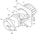
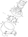
 実施形態1に係る穿孔装置における吸引切替装置Vは、図1に示すとおり、バキューム装置50(吸引装置)、バキューム装置50に繋がるホース本管16、分岐ホース15の配管は従来構成として示した図11~14と同様である。ホース本管16から分岐された各分岐ホース15は各穿孔ヘッドP(図12参照)に対応する接続ブロック17に接続されている。接続ブロック17の一面(表面)に分岐ホース15が接続される接続口が設けられる。接続ブロック17の反対面(裏面)に小径の接続口が設けられる。小径の接続口(図示外)に吸引切替装置Vに繋がるチューブ18が接続されている。糸立て皿13の前領域には、刺繍ヘッドSの縫い針に供給される上糸を巻いた各糸駒19が載置されている。吸引切替装置Vは、各接続ブロック17の後方に所定の間隔を空けて配置されている。吸引切替装置Vは、流路切替手段(流路切替機構)と接離切替手段(接離切替機構)で構成されている。
<Embodiment 1>
As shown in FIG. 1, the suction switching device V in the punching device according to the first embodiment is a vacuum device 50 (suction device), the hose main pipe 16 connected to the vacuum device 50, and the piping of the branch hose 15 are shown as conventional configurations. Same as 11-14. Each branch hose 15 branched from the hose main pipe 16 is connected to a connection block 17 corresponding to each perforation head P (see FIG. 12). A connection port to which the branch hose 15 is connected is provided on one surface (surface) of the connection block 17. A small-diameter connection port is provided on the opposite surface (back surface) of the connection block 17. A tube 18 connected to the suction switching device V is connected to a small-diameter connection port (not shown). In the front region of the thread stand 13, each thread spool 19 wound with an upper thread to be supplied to the sewing needle of the embroidery head S is placed. The suction switching device V is disposed behind each connection block 17 with a predetermined interval. The suction switching device V includes a flow path switching unit (flow path switching mechanism) and a contact / separation switching unit (contact / separation switching mechanism).
 [流路切替手段(流路切替機構)]
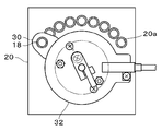
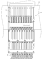
 図2に示すとおり、板状の支持プレート20(接続部材)が糸立て皿13上に立設される。支持プレート20は、糸立て皿13の下方から糸立て皿13に挿入されたボルト21で糸立て皿13に固定されている。図5に示すように、支持プレート20(接続部材)には、厚み方向に貫通する接続口20aが図12に示すポンス8(昇降棒6)と同数設けられている。接続口20aは、一定の間隔を空けて円弧状に配設されている。図12に示す穿孔ヘッドPの各昇降棒6の上端に接続されているチューブ11が図5に示す支持プレート20の各接続口20aの背面部に接続されている。支持プレート20に対するチューブ11の接続位置は図11に示す穿孔ヘッドPのポンス8(昇降棒6)の並び順と同じである。すなわち穿孔ヘッドPの最も右側の昇降棒6に接続されたチューブ11が、正面視において支持プレート20(図5参照)の最も右に位置する接続口20a(図5参照)に接続される。穿孔ヘッドPの最も左側の昇降棒6に接続されたチューブ11が、支持プレート20の最も左に位置する接続口20aに接続される。
[Flow path switching means (flow path switching mechanism)]
As shown in FIG. 2, a plate-like support plate 20 (connection member) is erected on the thread stand 13. The support plate 20 is fixed to the thread stand 13 with bolts 21 inserted into the thread stand 13 from below the thread stand 13. As shown in FIG. 5, the support plate 20 (connection member) is provided with the same number of connection ports 20 a penetrating in the thickness direction as the ponce 8 (elevating bar 6) shown in FIG. 12. The connection port 20a is arranged in an arc shape with a certain interval. Tubes 11 connected to the upper ends of the lifting rods 6 of the perforation head P shown in FIG. 12 are connected to the back surfaces of the connection ports 20a of the support plate 20 shown in FIG. The connection position of the tube 11 with respect to the support plate 20 is the same as the arrangement order of the ponses 8 (elevating bars 6) of the drilling head P shown in FIG. That is, the tube 11 connected to the rightmost lifting bar 6 of the punching head P is connected to the connection port 20a (see FIG. 5) located on the rightmost side of the support plate 20 (see FIG. 5) in a front view. The tube 11 connected to the leftmost lifting bar 6 of the drilling head P is connected to the connection port 20 a located on the leftmost side of the support plate 20.
 図2~5に示すように支持プレート20の前面側には、スタッド22が立設されており、スタッド22の先端に取付けプレート23が取り付けられている。取付けプレート23には、モータ軸が挿通する軸孔(図示外)が設けられている。モータ軸が取付けプレート23を貫通し、取付けプレート23から支持プレート20に向けて突出している。モータ軸の外周には、回転体25が固定されている。回転体25は、円筒状の基部25aと、基部25aより小径のガイド部25bとを一体に有している。ガイド部25bの先端側にはピン26が貫通して設けられている。ガイド部25bの外周には、移動体27が嵌合している。移動体27は、回転体25のガイド部25bの外周面に沿って軸線方向に摺動するように構成された筒状である。移動体27は、ガイド部25bのピン26が係合するガイド溝28を備えている。ガイド溝28はモータ軸と平行に延出している。ピン26は、径方向にガイド溝28から突出している。したがって、移動体27は、ガイド溝28に係合するピン26により回転不能に規制されて軸方向に直動(進退)するとともに、ピン26に押されて回転体25と一体的に回転する。 As shown in FIGS. 2 to 5, a stud 22 is erected on the front side of the support plate 20, and a mounting plate 23 is attached to the tip of the stud 22. The mounting plate 23 is provided with a shaft hole (not shown) through which the motor shaft is inserted. The motor shaft passes through the mounting plate 23 and protrudes from the mounting plate 23 toward the support plate 20. A rotating body 25 is fixed to the outer periphery of the motor shaft. The rotating body 25 integrally includes a cylindrical base portion 25a and a guide portion 25b having a smaller diameter than the base portion 25a. A pin 26 is provided through the tip of the guide portion 25b. A moving body 27 is fitted on the outer periphery of the guide portion 25b. The moving body 27 has a cylindrical shape configured to slide in the axial direction along the outer peripheral surface of the guide portion 25b of the rotating body 25. The moving body 27 includes a guide groove 28 with which the pin 26 of the guide portion 25b is engaged. The guide groove 28 extends in parallel with the motor shaft. The pin 26 protrudes from the guide groove 28 in the radial direction. Therefore, the movable body 27 is restricted to be non-rotatable by the pin 26 engaged with the guide groove 28 and moves linearly (advances and retreats) in the axial direction, and is pushed by the pin 26 and rotates integrally with the rotary body 25.
 図2~5に示すように移動体27には、連結具29により回動アーム30(回動部材)が固定されている。回動アーム30の基部が移動体27の中心に軸支されている。回動アーム30の端部側には吸引口30aが設けられている。吸引口30aは、回動アーム30が回転することで、支持プレート20に配設された複数の接続口20aに対して順に対向するように移動する。吸引口30aには、接続ブロック17からのチューブ18が接続されており、吸引口30aの反対面には、スポンジゴムからなるリング形状の当接部材31を備えている。なお、モータ24の他面側には、取付けプレート32を介して、回動アーム30の基準位置(原点)を検出するための検出器33が設けられている。 As shown in FIGS. 2 to 5, a rotating arm 30 (rotating member) is fixed to the moving body 27 by a connector 29. The base of the rotating arm 30 is pivotally supported at the center of the moving body 27. A suction port 30 a is provided on the end side of the rotating arm 30. The suction port 30a moves so as to face the plurality of connection ports 20a provided in the support plate 20 in order as the rotating arm 30 rotates. The tube 18 from the connection block 17 is connected to the suction port 30a, and a ring-shaped contact member 31 made of sponge rubber is provided on the opposite surface of the suction port 30a. A detector 33 for detecting the reference position (origin) of the rotating arm 30 is provided on the other surface side of the motor 24 via the mounting plate 32.
 [接離切替手段(接離切替機構)]
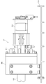
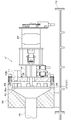
 図3,4に示すように支持プレート20の背面側には、エアシリンダ34が取り付けられている。エアシリンダ34のロッド35が支持プレート20を貫通してモータ24に向けて前方に突出している。ロッド35の軸心はモータ軸の軸心と同一線上である。ロッド35の先端は、回動アーム30を移動体27に固定している連結具29に連結されている。したがって、エアシリンダ34を駆動してロッド35を進退させると、移動体27が回転体25のガイド部25bに沿ってスライド移動する。これにより回動アーム30の位置が接続位置30Xと退避位置30Yへと切り替わる。具体的には、図3に示すとおり、エアシリンダ34のロッド35が後退すると、回動アーム30が支持プレート20方向(後方)に移動する。これにより回動アーム30の当接部材31が支持プレート20に設けられている接続口20aに押し当てられる(接続位置30X)。一方、図4に示すとおり、エアシリンダ34のロッド35が進出すると、回動アーム30がモータ24方向(前方)に移動する。これにより回動アーム30の当接部材31が接続口20aから切り離される(退避位置30Y)。
[Contact / separation switching means (contact / separation switching mechanism)]
As shown in FIGS. 3 and 4, an air cylinder 34 is attached to the back side of the support plate 20. A rod 35 of the air cylinder 34 penetrates the support plate 20 and protrudes forward toward the motor 24. The axis of the rod 35 is collinear with the axis of the motor shaft. The tip of the rod 35 is connected to a connector 29 that fixes the rotating arm 30 to the moving body 27. Therefore, when the air cylinder 34 is driven to move the rod 35 forward and backward, the moving body 27 slides along the guide portion 25 b of the rotating body 25. As a result, the position of the rotating arm 30 is switched between the connection position 30X and the retracted position 30Y. Specifically, as shown in FIG. 3, when the rod 35 of the air cylinder 34 moves backward, the rotating arm 30 moves in the direction of the support plate 20 (rearward). Thereby, the contact member 31 of the rotation arm 30 is pressed against the connection port 20a provided in the support plate 20 (connection position 30X). On the other hand, as shown in FIG. 4, when the rod 35 of the air cylinder 34 advances, the rotating arm 30 moves in the direction of the motor 24 (forward). Thereby, the contact member 31 of the rotating arm 30 is separated from the connection port 20a (retracted position 30Y).
 [吸引切替装置Vの作動]
 被加工物である皮革シートに穿孔処理を施す場合は、あらかじめ、穿孔処理による抜き屑を回収するためにバキューム装置50を作動させておく。そして、周知のとおり、穿孔柄データにしたがって皮革シートを保持した保持枠をテーブル上面でX、Y方向に移動させながら、穿孔ヘッドPにより穿孔処理を皮革シートに施す。穿孔処理の過程において、吸引切替装置は以下のように作動する。
[Operation of suction switching device V]
When a punching process is performed on a leather sheet that is a workpiece, the vacuum device 50 is operated in advance in order to collect scraps from the punching process. Then, as is well known, a perforating process is performed on the leather sheet by the perforating head P while moving the holding frame holding the leather sheet in the X and Y directions on the table top according to the perforated pattern data. In the course of the drilling process, the suction switching device operates as follows.
 図6は、穿孔ヘッドPの最も右側に位置するポンス8を使用して穿孔処理を施す場合の回動アーム30の位置を示している。回動アーム30は、流路切替手段の一構成であるモータ24の作動により、支持プレート20に対して移動する。穿孔ヘッドPの最も右側に位置するポンス8(昇降棒6)のチューブ11が接続されている接続口20aに回動アーム30が位置合わせされている。また、図3に示すとおり、接離切替手段の一構成であるエアシリンダ34の作動により、回動アーム30の当接部材31が接続口20aに垂直に押し当てられている(接続位置30X)。したがって、分岐ホース15が繋がる接続ブロック17からのチューブ18とポンス8(昇降棒6)に接続されているチューブ11とが隙間なく接続されている。このことから流路の気密性を保ったまま、穿孔ヘッドPの最も右側に位置するポンス8(昇降棒6)のみがバキューム装置50により吸引される。 FIG. 6 shows the position of the rotating arm 30 when the punching process is performed using the ponce 8 positioned on the rightmost side of the punching head P. The rotating arm 30 moves with respect to the support plate 20 by the operation of the motor 24 which is one configuration of the flow path switching unit. The rotating arm 30 is aligned with the connection port 20a to which the tube 11 of the ponce 8 (lifting rod 6) located on the rightmost side of the drilling head P is connected. Further, as shown in FIG. 3, the contact member 31 of the rotating arm 30 is pressed vertically against the connection port 20a by the operation of the air cylinder 34 which is one configuration of the contact / separation switching means (connection position 30X). . Therefore, the tube 18 from the connection block 17 to which the branch hose 15 is connected and the tube 11 connected to the ponce 8 (lifting rod 6) are connected without a gap. For this reason, only the ponce 8 (lifting rod 6) located on the rightmost side of the drilling head P is sucked by the vacuum device 50 while keeping the airtightness of the flow path.
 図7は、穿孔処理を施すポンス8を穿孔ヘッドPの最も左側に位置するポンス8に切り替えた場合の回動アーム30の位置を示している。エアシリンダ34が作動し、回動アーム30の位置が接続位置30X(図3参照)から退避位置30Y(図4参照)に移動することにより、回動アーム30の当接部材31が接続口20aから離間する。続いて、モータ24が作動し、回動アーム30が左方向に回動する。回動アーム30の当接部材31が支持プレート20に対して穿孔ヘッドPの最も左側に位置するポンス8(昇降棒6)のチューブ11が接続されている接続口20aに対向する。エアシリンダ34が作動し、回動アーム30の位置が退避位置30Yから接続位置30Xに移動する。これにより、回動アーム30の当接部材31が接続口20aに押し当てられる。かくして、分岐ホース15が繋がる接続ブロック17からのチューブ18とポンス8(昇降棒6)に接続されているチューブ11とが接続される。そして吸引流路が穿孔ヘッドPの最も左側に位置するポンス8(昇降棒6)に連結するように切替えられる。なお、吸引切替装置Vの作動(吸引流路の切替え)は、使用するポンス8(昇降棒6)の切替えに同期している。穿孔柄データに基づいて使用されるポンス8(昇降棒6)が切り替えられると、吸引流路も自動的に当該ポンス8(昇降棒6)に連結するように切り替えられる。 FIG. 7 shows the position of the rotating arm 30 when the pierce 8 to be punched is switched to the ponce 8 positioned on the leftmost side of the punching head P. When the air cylinder 34 operates and the position of the rotating arm 30 moves from the connection position 30X (see FIG. 3) to the retracted position 30Y (see FIG. 4), the contact member 31 of the rotating arm 30 moves to the connection port 20a. Separate from. Subsequently, the motor 24 is operated, and the rotating arm 30 is rotated leftward. The contact member 31 of the rotating arm 30 faces the connection port 20a to which the tube 11 of the ponse 8 (lifting rod 6) located on the leftmost side of the drilling head P is connected to the support plate 20. The air cylinder 34 operates, and the position of the rotating arm 30 moves from the retracted position 30Y to the connection position 30X. Thereby, the contact member 31 of the rotation arm 30 is pressed against the connection port 20a. Thus, the tube 18 from the connection block 17 to which the branch hose 15 is connected and the tube 11 connected to the ponce 8 (elevating bar 6) are connected. Then, the suction channel is switched so as to be connected to the ponce 8 (lifting rod 6) located on the leftmost side of the punching head P. Note that the operation of the suction switching device V (switching of the suction flow path) is synchronized with the switching of the pons 8 (elevating bar 6) to be used. When the pons 8 (elevating bar 6) to be used is switched based on the perforated pattern data, the suction flow path is also switched to automatically connect to the pons 8 (elevating bar 6).
 上記に説明したとおり、吸引切替装置Vにより、バキューム装置50に繋がる吸引経路を穿孔処理を施すポンス8(昇降棒6)だけに接続して吸引する。この構造であるため、従来技術と比べて流路の気密性が高く、抜き屑をバキューム装置50によって効率よく吸引することが可能である。 As explained above, the suction switching device V connects the suction path connected to the vacuum device 50 only to the ponce 8 (elevating rod 6) that performs the perforating process, and performs suction. Due to this structure, the airtightness of the flow path is higher than in the prior art, and the scraps can be efficiently sucked by the vacuum device 50.
<実施形態2>
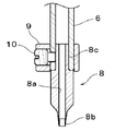
 図8~10に示すとおり、実施形態2における吸引切替装置V’は、内部に空洞部36aを有する円筒状のマニホールド36(接続部材)を備えている。マニホールド36の片側面に図1に示すバキューム装置50のホース本管16に繋がる分岐ホース15が接続されている。マニホールド36の反対面には、マニホールド36の内部と貫通する接続口36bが設けられている。接続口36bの数は穿孔ヘッドPのポンス8(昇降棒6)と同数である。接続口36bは一定の間隔を空けて環状に配設されている。そして、穿孔ヘッドP(図12参照)の各昇降棒6の上端に接続されているチューブ11は、この接続口36bにそれぞれ接続されている。接続口36bが配設された環状の中心軸上に、流路切替手段と接離切替手段が設けられている。また、実施形態1における回動アーム30に相当する部材として回転プレート37(回動部材)が設けられている。回転プレート37(回動部材)はマニホールド36の空洞部36aに収納され、接離切替手段の一構成であるエアシリンダ34のロッド35の先端に連結されている。
<Embodiment 2>
As shown in FIGS. 8 to 10, the suction switching device V ′ in the second embodiment includes a cylindrical manifold 36 (connection member) having a hollow portion 36a therein. A branch hose 15 connected to the hose main pipe 16 of the vacuum device 50 shown in FIG. 1 is connected to one side surface of the manifold 36. A connection port 36 b that penetrates the inside of the manifold 36 is provided on the opposite surface of the manifold 36. The number of connection ports 36b is the same as the number of ponses 8 (elevating bars 6) of the drilling head P. The connection ports 36b are annularly arranged with a certain interval. And the tube 11 connected to the upper end of each raising / lowering rod 6 of the perforation head P (refer FIG. 12) is each connected to this connection port 36b. A channel switching means and a contact / separation switching means are provided on the annular central axis in which the connection port 36b is provided. Further, a rotating plate 37 (rotating member) is provided as a member corresponding to the rotating arm 30 in the first embodiment. The rotating plate 37 (rotating member) is housed in the hollow portion 36a of the manifold 36, and is connected to the tip of the rod 35 of the air cylinder 34 which is one configuration of the contact / separation switching means.
 図10に示すように回転プレート37は、ひとつの当接部材38と複数個の密閉部材39を備えており、接続口36bが配設された円形と同心・同径上で、各接続口36bと同じ間隔をもって配設されている。当接部材38は実施形態1と同じく、スポンジゴムからなるリング形状である。また、回転プレート37は、当接部材38が取付けられた位置だけに厚み方向に貫通する吸引口40が設けられている。密閉部材39は、ゴムからなる先端に吸着部を有した形状で、回転プレート37にネジ止めされている。穿孔処理を施すポンス8(昇降棒6)以外のポンス8(昇降棒6)の各接続口36bを塞ぐためのフタとして機能する。 As shown in FIG. 10, the rotating plate 37 includes one contact member 38 and a plurality of sealing members 39, and is concentric with the same diameter as the circular shape in which the connection port 36b is disposed. Are arranged at the same interval. Similar to the first embodiment, the contact member 38 has a ring shape made of sponge rubber. The rotary plate 37 is provided with a suction port 40 that penetrates in the thickness direction only at a position where the contact member 38 is attached. The sealing member 39 has a shape having a suction portion at the tip made of rubber, and is screwed to the rotary plate 37. It functions as a lid for closing each connection port 36b of the pons 8 (elevating bar 6) other than the pons 8 (elevating bar 6) to be subjected to the perforating process.
 図9,10に示すように実施形態2の吸引切替装置V’は、実施形態1と同様に、流路切替手段の一構成であるモータ24により回転プレート37を回転させる。吸引口を有する当接部材38が穿孔処理を施すポンス8(昇降棒6)の接続口36bに対応するように回転プレート37の位置を切り替える。そして、実施形態1と同様に、接離切替手段の一構成であるエアシリンダ34が作動し、回転プレート37の位置が退避位置37Yから接続位置(図示省略)に移動する。このことにより、回転プレート37の当接部材38が接続口36bに押し当てられるとともに、各密閉部材39が穿孔処理を施すポンス8(昇降棒6)以外のポンス8(昇降棒6)の各接続口36bに押し当てられる。ポンス8(昇降棒6)以外のポンス8(昇降棒6)の各接続口36bは各密閉部材39に塞がれているため、穿孔処理を施すポンス8(昇降棒6)のみが吸引されることになる。 As shown in FIGS. 9 and 10, the suction switching device V ′ of the second embodiment rotates the rotating plate 37 by the motor 24 that is one component of the flow path switching means, as in the first embodiment. The position of the rotary plate 37 is switched so that the contact member 38 having a suction port corresponds to the connection port 36b of the ponce 8 (elevating rod 6) that performs the perforating process. As in the first embodiment, the air cylinder 34, which is one component of the contact / separation switching means, is operated, and the position of the rotating plate 37 is moved from the retracted position 37Y to the connected position (not shown). As a result, the contact member 38 of the rotating plate 37 is pressed against the connection port 36b, and each connection of the pons 8 (elevating bar 6) other than the pons 8 (elevating bar 6) to which each sealing member 39 performs perforation processing. It is pressed against the mouth 36b. Since each connection port 36b of the pons 8 (elevating bar 6) other than the pons 8 (elevating bar 6) is closed by the respective sealing members 39, only the pons 8 (elevating bar 6) to be perforated are sucked. It will be.
 実施形態1、2の穿孔装置は、次のような効果を有している。 The punching apparatus of Embodiments 1 and 2 has the following effects.
 上記穿孔装置は、複数の昇降棒6(中空棒)のうち穿孔処理を施す昇降棒6のみを吸引するための吸引切替装置V、V’を有している。これにより、複数の昇降棒6のうち穿孔処理を施さない昇降棒6においては、吸引を行わない。そのため、バキューム装置50(吸引装置)の吸引力を穿孔処理を施す昇降棒6に集中させることができる。その結果、抜き屑を排出するための流路の気密性を高め、バキューム装置50の抜き屑を吸引する吸引効率が向上する。 The punching device includes suction switching devices V and V ′ for sucking only the lifting rod 6 that performs the punching processing among the plurality of lifting rods 6 (hollow rods). Thereby, in the raising / lowering rod 6 which does not perforate among the several raising / lowering rods 6, suction is not performed. Therefore, the suction force of the vacuum device 50 (suction device) can be concentrated on the elevating rod 6 that performs the drilling process. As a result, the airtightness of the flow path for discharging the scraps is improved, and the suction efficiency for sucking the scraps of the vacuum device 50 is improved.
 また、吸引切替装置V、V’は、複数の昇降棒6から選択した昇降棒6に応じて流路を切り替える流路切替手段を有している。これにより、複数の昇降棒6のうち穿孔処理を施す昇降棒6に対応した流路のみを吸引することができる。 Further, the suction switching devices V, V ′ have flow path switching means for switching the flow path according to the lifting bar 6 selected from the plurality of lifting bars 6. Thereby, only the flow path corresponding to the raising / lowering rod 6 which perforates among the several raising / lowering rods 6 can be attracted | sucked.
 また、吸引切替装置V、V’は、流路切替手段によって切り替えられた吸引流路の中間部位において接続と分離を切り替える接離切替手段を有する。したがって吸引流路は、選択した昇降棒6に対しての接続と分離とが流路切替手段によって物理的に切り替えられる。 Further, the suction switching devices V and V ′ have contact / separation switching means for switching connection and separation at an intermediate portion of the suction flow path switched by the flow path switching means. Accordingly, the suction channel is physically switched between connection and separation with respect to the selected lifting rod 6 by the channel switching means.
 また、接離切替手段による吸引流路の分離を行った後に、流路切替手段によって複数の昇降棒6(中空棒)のうち選択された昇降棒6に応ずる吸引流路を選択するように流路を切り替える。この構成であることから、分離しないで切り替える構成に比べ当接部材の摩耗を防止できると共に、モータ24(駆動源)等にかかる負荷を低減させることができる。 In addition, after the suction flow path is separated by the contact / separation switching means, the flow path switching means selects the suction flow path corresponding to the selected lift bar 6 among the plurality of lift bars 6 (hollow bars). Switch the road. Since it is this structure, compared with the structure switched without isolate | separating, while being able to prevent abrasion of a contact member, the load concerning the motor 24 (drive source) etc. can be reduced.
 また、流路切替手段は、円弧上に配された複数の接続口20a、36bを有する。複数の接続口20a、36bを直線状に配設する構成よりもコンパクトに構成することができる。さらに流路切替手段は、複数の接続口20a、36bに対する吸引口30a、40の切り替えについて、モータ24(駆動源)の回転軸を利用する。この構成であることから流路切替手段に複雑な構成を採用することなく流路切替手段をコンパクトにすることができる。 The flow path switching means has a plurality of connection ports 20a and 36b arranged on an arc. The plurality of connection ports 20a and 36b can be configured more compactly than the configuration in which the connection ports 20a and 36b are arranged linearly. Furthermore, the flow path switching means uses the rotating shaft of the motor 24 (drive source) for switching the suction ports 30a, 40 to the plurality of connection ports 20a, 36b. Because of this configuration, the flow path switching means can be made compact without adopting a complicated configuration for the flow path switching means.
 接離切替手段の回動アーム30、回転プレート37がその回動中心と同軸上に沿って往復移動することで、複数の接続口20a、36bと吸引口30a、40との接続と分離の切り替えを行う。これにより、吸引口30a、40に設けられた当接部材が接続口20a、36bに垂直に押し当てられる。そのため、吸引口と接続口とが隙間なく接続されて気密性を保つことができる。 Switching of connection and separation between the plurality of connection ports 20a and 36b and the suction ports 30a and 40 is performed by reciprocating the rotation arm 30 and the rotation plate 37 of the contact / separation switching unit along the same axis as the rotation center. I do. Thereby, the contact member provided in the suction ports 30a and 40 is pressed perpendicularly to the connection ports 20a and 36b. Therefore, the suction port and the connection port are connected without a gap, and airtightness can be maintained.
 また、吸引切替装置V、V’は、穿孔ヘッドP毎に設けられる。そのため穿孔ヘッドPが増加しても穿孔ヘッドP毎に吸引切替装置V、V’を設けることができる。かくして本構成は、穿孔ヘッドPの数の変更に柔軟に対応でき、吸引処理の能力も維持できる。 Further, the suction switching devices V and V ′ are provided for each perforation head P. Therefore, even if the number of punching heads P increases, the suction switching devices V and V ′ can be provided for each punching head P. Thus, this configuration can flexibly cope with a change in the number of perforation heads P and can also maintain the suction processing capability.
 以上、本発明の実施形態について説明したが、本発明の穿孔装置は、本実施の形態に限定されず、その他各種の形態で実施することができるものである。 As mentioned above, although embodiment of this invention was described, the punching apparatus of this invention is not limited to this embodiment, It can implement with other various forms.
 なお、実施形態は、刺繍ヘッドSと穿孔ヘッドPからなるペアを2つ備えているが、これに限られず、2つ以上のペアで構成する刺繍機、穿孔ヘッドPのみを複数備えた穿孔装置、または穿孔ヘッドPをひとつだけ備えた穿孔装置であってもよい。 The embodiment includes two pairs of the embroidery head S and the punching head P. However, the present invention is not limited to this, and the punching apparatus includes a plurality of embroidery machines configured by two or more pairs and only the punching heads P. Alternatively, it may be a punching device provided with only one punching head P.

Claims (7)

  1.  穿孔装置であって、
     上下動する複数の中空棒と、該中空棒の先端にそれぞれ設けられ軸方向に貫通する貫通孔を備えた穿孔具と、を含む穿孔ヘッドと、
     前記穿孔ヘッドの穿孔処理による抜き屑を吸引する吸引装置と、
     前記穿孔具に設けられた貫通孔と前記吸引装置の間を通じる吸引流路と、
     前記複数の中空棒のうち穿孔処理を施す中空棒のみを吸引するように前記吸引流路を変更する吸引切替装置と、を有する穿孔装置。
    A drilling device,
    A drilling head including a plurality of hollow bars that move up and down, and a punching tool that is provided at the tip of the hollow bar and has a through-hole penetrating in the axial direction;
    A suction device for sucking out scraps from the punching process of the punching head;
    A suction flow path between a through hole provided in the punch and the suction device;
    And a suction switching device that changes the suction flow path so as to suck only the hollow rod to be perforated among the plurality of hollow rods.
  2.  請求項1に記載の穿孔装置であって、
     前記吸引切替装置は、前記複数の中空棒のうち選択された中空棒に応じて吸引流路を切り替える流路切替機構を有する穿孔装置。
    The perforating apparatus according to claim 1,
    The suction switching device is a piercing device having a channel switching mechanism that switches a suction channel according to a hollow rod selected from the plurality of hollow rods.
  3.  請求項2に記載の穿孔装置であって、
     前記吸引切替装置は、前記流路切替機構によって切り替えられた吸引流路の中間部位において前記吸引流路の流路の延出方向に往復移動することで選択された前記中空棒に対して前記吸引流路が接続された状態と分離した状態とに切り替える接離切替機構を有する穿孔装置。
    The perforating apparatus according to claim 2,
    The suction switching device is configured to suck the hollow rod selected by reciprocating in the extending direction of the suction channel at an intermediate portion of the suction channel switched by the channel switching mechanism. A perforating apparatus having a contact / separation switching mechanism for switching between a state in which a flow path is connected and a state in which the flow path is separated.
  4.  請求項3に記載の穿孔装置であって、
     前記流路切替機構は、前記接離切替機構による吸引流路の分離を行った状態において、前記複数の中空棒のうち選択された中空棒に応ずる吸引流路に切り替える穿孔装置。
    The perforating apparatus according to claim 3,
    The flow path switching mechanism is a piercing device that switches to a suction flow path corresponding to a selected hollow bar among the plurality of hollow bars in a state where the suction flow path is separated by the contact / separation switching mechanism.
  5.  請求項2から請求項4のいずれか1つに記載の穿孔装置であって、
     前記流路切替機構は、
     円弧上に配された複数の接続口が設けられた接続部材と、該円弧の中心を回動中心として回動することで前記複数の接続口のうち一つの接続口と連通する吸引口を備えた回動部材を有する穿孔装置。
    The perforating apparatus according to any one of claims 2 to 4,
    The flow path switching mechanism is
    A connection member provided with a plurality of connection ports arranged on an arc, and a suction port that communicates with one of the plurality of connection ports by rotating about the center of the arc. Drilling device having a rotating member.
  6.  請求項2~5のいずれか1つに記載の穿孔装置であって、
     前記流路切替機構は、
     円弧上に配された複数の接続口が設けられた接続部材と、該円弧の中心を回動中心として回動することで前記複数の接続口のうち一つの接続口と連通する吸引口を備えた回動部材を有し、
     前記吸引切替装置は、前記回動部材がその回動中心と同軸上に沿って往復移動することで、前記各接続口と前記吸引口との接続と分離の切り替えを行う接離切替機構を有する穿孔装置。
    A perforating apparatus according to any one of claims 2 to 5,
    The flow path switching mechanism is
    A connection member provided with a plurality of connection ports arranged on an arc, and a suction port that communicates with one of the plurality of connection ports by rotating about the center of the arc. A rotating member,
    The suction switching device includes a contact / separation switching mechanism that switches connection and separation between the connection ports and the suction ports by reciprocating the rotation member along the same axis as the rotation center. Drilling device.
  7.  請求項1から請求項6のいずれか1つに記載の穿孔装置であって、
     前記吸引切替装置は、前記穿孔ヘッド毎に設けられている穿孔装置。
    The perforating apparatus according to any one of claims 1 to 6,
    The suction switching device is a punching device provided for each punching head.
PCT/JP2018/015976 2017-04-25 2018-04-18 Punching device WO2018198900A1 (en)

Priority Applications (5)

Application Number Priority Date Filing Date Title
US16/607,811 US11511452B2 (en) 2017-04-25 2018-04-18 Punching device
CN201880027176.2A CN110651079B (en) 2017-04-25 2018-04-18 Punching device
JP2019514423A JP7013036B2 (en) 2017-04-25 2018-04-18 Drilling device
KR1020197033425A KR102427391B1 (en) 2017-04-25 2018-04-18 punching device
EP18790828.0A EP3617361B1 (en) 2017-04-25 2018-04-18 Punching device

Applications Claiming Priority (2)

Application Number Priority Date Filing Date Title
JP2017085848 2017-04-25
JP2017-085848 2017-04-25

Publications (1)

Publication Number Publication Date
WO2018198900A1 true WO2018198900A1 (en) 2018-11-01

Family

ID=63919216

Family Applications (1)

Application Number Title Priority Date Filing Date
PCT/JP2018/015976 WO2018198900A1 (en) 2017-04-25 2018-04-18 Punching device

Country Status (6)

Country Link
US (1) US11511452B2 (en)
EP (1) EP3617361B1 (en)
JP (1) JP7013036B2 (en)
KR (1) KR102427391B1 (en)
CN (1) CN110651079B (en)
WO (1) WO2018198900A1 (en)

Citations (5)

* Cited by examiner, † Cited by third party
Publication number Priority date Publication date Assignee Title
JPH0530759A (en) * 1991-07-19 1993-02-05 Fuji Electric Co Ltd Interrupting/conducting mos circuit
JPH09234698A (en) * 1995-12-25 1997-09-09 Ngk Insulators Ltd Successive working method of sheet
JP2000108095A (en) * 1998-10-05 2000-04-18 Fujimori Kogyo Co Ltd Punching device
WO2015076389A1 (en) 2013-11-25 2015-05-28 東海工業ミシン株式会社 Embroidery sewing machine comprising perforating head
JP2018024089A (en) * 2016-08-12 2018-02-15 サンスター カンパニー,リミテッド Suction device applied to punching machine

Family Cites Families (23)

* Cited by examiner, † Cited by third party
Publication number Priority date Publication date Assignee Title
US2646095A (en) * 1949-03-24 1953-07-21 Robert Legg Ltd Machine for cutting tobacco and the like
US3194095A (en) * 1962-12-31 1965-07-13 Lloyd P Buck Punch confett remover
NL7002316A (en) * 1970-02-19 1971-08-23
DE2062745C2 (en) * 1970-12-19 1983-10-27 Ramisch Kleinewefers Gmbh, 4150 Krefeld Method for cutting out dough figures, for example pretzels, from a sheet of dough
DE3420763A1 (en) 1984-06-04 1985-12-05 Rudolf 5450 Neuwied Reich Process and apparatus for the selective embroidering and/or engraving and/or painting and/or perforating of material webs or blanks consisting of materials permeable or impermeable to needles and drills
US4599926A (en) * 1984-07-16 1986-07-15 Preston Engravers, Inc. Rotary cutting dies with vacuum assist to cut and clear waste
DE3629968A1 (en) * 1986-09-03 1988-03-10 Messerschmitt Boelkow Blohm DEVICE FOR RECEIVING AND DEPOSITING CUTS
US5778806A (en) 1990-12-26 1998-07-14 Ralph's Industrial Sewing Machine Company Sewing and material removal assembly
JP2721947B2 (en) 1993-06-17 1998-03-04 極東産機株式会社 Noodle boiling equipment
JPH07157117A (en) * 1993-12-08 1995-06-20 Fuji Photo Film Co Ltd Board shape or box shape vacuum chuck device
JP2736602B2 (en) 1994-01-10 1998-04-02 徳男 高橋 How to form overholes in embroidery
DE69529350T2 (en) * 1994-04-13 2003-10-16 Winkler & Duennebier Ag Cylinder for attaching a flexible stamping tool
US5906702A (en) * 1995-02-07 1999-05-25 Precision Dynamics Corporation Method and apparatus for removing profiles
US5836226A (en) 1995-12-25 1998-11-17 Ngk Insulators, Ltd. Apparatus for progressively feeding and machining sheet material
DE10153784B4 (en) * 2001-04-12 2005-02-03 Trumpf Sachsen Gmbh Modular control system for a loading device with targeted suction pad control
CH695854A5 (en) * 2002-09-12 2006-09-29 Bobst Sa Method and blank separating device in a plate member cutting machine.
JP4862907B2 (en) * 2009-03-24 2012-01-25 ブラザー工業株式会社 Multi-needle sewing machine
JP5779450B2 (en) * 2011-08-24 2015-09-16 株式会社島精機製作所 Cutting machine equipped with perforation device and perforation dust removing method
CN106133227B (en) * 2014-03-27 2018-11-30 东海工业缝纫机株式会社 The embroidery machine of cord material can be sutured
JP6448997B2 (en) * 2014-11-26 2019-01-09 蛇の目ミシン工業株式会社 Sewing machine threading device
US9988221B2 (en) * 2014-12-11 2018-06-05 Translogic Corporation Carrier brake for pneumatic transport system
US10814498B2 (en) * 2017-11-07 2020-10-27 Berkshire Grey, Inc. Systems and methods for providing dynamic vacuum pressure at an end effector using a single vacuum source
DE102019110913A1 (en) * 2019-04-26 2020-10-29 J. Schmalz Gmbh Area suction cup

Patent Citations (5)

* Cited by examiner, † Cited by third party
Publication number Priority date Publication date Assignee Title
JPH0530759A (en) * 1991-07-19 1993-02-05 Fuji Electric Co Ltd Interrupting/conducting mos circuit
JPH09234698A (en) * 1995-12-25 1997-09-09 Ngk Insulators Ltd Successive working method of sheet
JP2000108095A (en) * 1998-10-05 2000-04-18 Fujimori Kogyo Co Ltd Punching device
WO2015076389A1 (en) 2013-11-25 2015-05-28 東海工業ミシン株式会社 Embroidery sewing machine comprising perforating head
JP2018024089A (en) * 2016-08-12 2018-02-15 サンスター カンパニー,リミテッド Suction device applied to punching machine

Non-Patent Citations (1)

* Cited by examiner, † Cited by third party
Title
See also references of EP3617361A4

Also Published As

Publication number Publication date
EP3617361B1 (en) 2021-11-24
EP3617361A4 (en) 2021-01-13
US20200130217A1 (en) 2020-04-30
CN110651079A (en) 2020-01-03
KR20190139265A (en) 2019-12-17
CN110651079B (en) 2021-12-21
JP7013036B2 (en) 2022-01-31
US11511452B2 (en) 2022-11-29
KR102427391B1 (en) 2022-08-01
JPWO2018198900A1 (en) 2020-02-27
EP3617361A1 (en) 2020-03-04

Similar Documents

Publication Publication Date Title
KR101117567B1 (en) Jig for a NC or CNC machine
WO2018101014A1 (en) Boring device and embroidery machine provided with said boring device
CN110370373B (en) Accounting document drilling machine
JPH06304367A (en) Holder for processed fabric
JP4362449B2 (en) Buttonhole sewing machine
WO2018198900A1 (en) Punching device
JP2005138263A (en) Apparatus for press-fitting bush
KR100346978B1 (en) A punching and cutting apparatus
CN105689508A (en) Automatic conveying type porous stamping device
KR200188901Y1 (en) A metallic plate punching and cutting apparatus
JP6550619B2 (en) Welding bolt supply device
JP6042507B1 (en) Button hole sewing machine clamping mechanism
JP5193887B2 (en) Punch press
CN111001851A (en) Continuous punching mechanism for processing of stitch scissors
CN212955668U (en) Towards embroidery integral type embroidery machine
CN210765848U (en) Embroidery cloth rapid clamping device and computerized embroidery machine
JP2017056477A (en) Laser nozzle replacing method and laser processing machine
CN211304925U (en) PCB copper board separator
JP4221377B2 (en) Buttonhole sewing machine
CN219254806U (en) Positioning and clamping device and ring spinning frame roller stand multi-station puncher with same
JPH10118994A (en) Centering device for mark on work in boring device
CN214161459U (en) Piston top drilling device
CN212121727U (en) Continuous punching mechanism for processing of stitch scissors
JP2018011846A (en) sewing machine
JPH0715753Y2 (en) Test piece making device

Legal Events

Date Code Title Description
121 Ep: the epo has been informed by wipo that ep was designated in this application

Ref document number: 18790828

Country of ref document: EP

Kind code of ref document: A1

ENP Entry into the national phase

Ref document number: 2019514423

Country of ref document: JP

Kind code of ref document: A

NENP Non-entry into the national phase

Ref country code: DE

ENP Entry into the national phase

Ref document number: 20197033425

Country of ref document: KR

Kind code of ref document: A

ENP Entry into the national phase

Ref document number: 2018790828

Country of ref document: EP

Effective date: 20191125