WO2018155659A1 - Roulement à rouleaux - Google Patents
Roulement à rouleaux Download PDFInfo
- Publication number
- WO2018155659A1 WO2018155659A1 PCT/JP2018/006824 JP2018006824W WO2018155659A1 WO 2018155659 A1 WO2018155659 A1 WO 2018155659A1 JP 2018006824 W JP2018006824 W JP 2018006824W WO 2018155659 A1 WO2018155659 A1 WO 2018155659A1
- Authority
- WO
- WIPO (PCT)
- Prior art keywords
- shield
- press
- outer ring
- rolling bearing
- diameter
- Prior art date
Links
Images


Classifications
-
- F—MECHANICAL ENGINEERING; LIGHTING; HEATING; WEAPONS; BLASTING
- F16—ENGINEERING ELEMENTS AND UNITS; GENERAL MEASURES FOR PRODUCING AND MAINTAINING EFFECTIVE FUNCTIONING OF MACHINES OR INSTALLATIONS; THERMAL INSULATION IN GENERAL
- F16C—SHAFTS; FLEXIBLE SHAFTS; ELEMENTS OR CRANKSHAFT MECHANISMS; ROTARY BODIES OTHER THAN GEARING ELEMENTS; BEARINGS
- F16C19/00—Bearings with rolling contact, for exclusively rotary movement
- F16C19/02—Bearings with rolling contact, for exclusively rotary movement with bearing balls essentially of the same size in one or more circular rows
- F16C19/04—Bearings with rolling contact, for exclusively rotary movement with bearing balls essentially of the same size in one or more circular rows for radial load mainly
- F16C19/06—Bearings with rolling contact, for exclusively rotary movement with bearing balls essentially of the same size in one or more circular rows for radial load mainly with a single row or balls
-
- F—MECHANICAL ENGINEERING; LIGHTING; HEATING; WEAPONS; BLASTING
- F16—ENGINEERING ELEMENTS AND UNITS; GENERAL MEASURES FOR PRODUCING AND MAINTAINING EFFECTIVE FUNCTIONING OF MACHINES OR INSTALLATIONS; THERMAL INSULATION IN GENERAL
- F16C—SHAFTS; FLEXIBLE SHAFTS; ELEMENTS OR CRANKSHAFT MECHANISMS; ROTARY BODIES OTHER THAN GEARING ELEMENTS; BEARINGS
- F16C19/00—Bearings with rolling contact, for exclusively rotary movement
- F16C19/22—Bearings with rolling contact, for exclusively rotary movement with bearing rollers essentially of the same size in one or more circular rows, e.g. needle bearings
- F16C19/24—Bearings with rolling contact, for exclusively rotary movement with bearing rollers essentially of the same size in one or more circular rows, e.g. needle bearings for radial load mainly
- F16C19/26—Bearings with rolling contact, for exclusively rotary movement with bearing rollers essentially of the same size in one or more circular rows, e.g. needle bearings for radial load mainly with a single row of rollers
-
- F—MECHANICAL ENGINEERING; LIGHTING; HEATING; WEAPONS; BLASTING
- F16—ENGINEERING ELEMENTS AND UNITS; GENERAL MEASURES FOR PRODUCING AND MAINTAINING EFFECTIVE FUNCTIONING OF MACHINES OR INSTALLATIONS; THERMAL INSULATION IN GENERAL
- F16C—SHAFTS; FLEXIBLE SHAFTS; ELEMENTS OR CRANKSHAFT MECHANISMS; ROTARY BODIES OTHER THAN GEARING ELEMENTS; BEARINGS
- F16C33/00—Parts of bearings; Special methods for making bearings or parts thereof
- F16C33/72—Sealings
- F16C33/76—Sealings of ball or roller bearings
- F16C33/78—Sealings of ball or roller bearings with a diaphragm, disc, or ring, with or without resilient members
- F16C33/7816—Details of the sealing or parts thereof, e.g. geometry, material
- F16C33/783—Details of the sealing or parts thereof, e.g. geometry, material of the mounting region
-
- F—MECHANICAL ENGINEERING; LIGHTING; HEATING; WEAPONS; BLASTING
- F16—ENGINEERING ELEMENTS AND UNITS; GENERAL MEASURES FOR PRODUCING AND MAINTAINING EFFECTIVE FUNCTIONING OF MACHINES OR INSTALLATIONS; THERMAL INSULATION IN GENERAL
- F16C—SHAFTS; FLEXIBLE SHAFTS; ELEMENTS OR CRANKSHAFT MECHANISMS; ROTARY BODIES OTHER THAN GEARING ELEMENTS; BEARINGS
- F16C33/00—Parts of bearings; Special methods for making bearings or parts thereof
- F16C33/72—Sealings
- F16C33/76—Sealings of ball or roller bearings
- F16C33/78—Sealings of ball or roller bearings with a diaphragm, disc, or ring, with or without resilient members
- F16C33/784—Sealings of ball or roller bearings with a diaphragm, disc, or ring, with or without resilient members mounted to a groove in the inner surface of the outer race and extending toward the inner race
- F16C33/7843—Sealings of ball or roller bearings with a diaphragm, disc, or ring, with or without resilient members mounted to a groove in the inner surface of the outer race and extending toward the inner race with a single annular sealing disc
- F16C33/7846—Sealings of ball or roller bearings with a diaphragm, disc, or ring, with or without resilient members mounted to a groove in the inner surface of the outer race and extending toward the inner race with a single annular sealing disc with a gap between the annular disc and the inner race
- F16C33/785—Bearing shields made of sheet metal
-
- F—MECHANICAL ENGINEERING; LIGHTING; HEATING; WEAPONS; BLASTING
- F16—ENGINEERING ELEMENTS AND UNITS; GENERAL MEASURES FOR PRODUCING AND MAINTAINING EFFECTIVE FUNCTIONING OF MACHINES OR INSTALLATIONS; THERMAL INSULATION IN GENERAL
- F16C—SHAFTS; FLEXIBLE SHAFTS; ELEMENTS OR CRANKSHAFT MECHANISMS; ROTARY BODIES OTHER THAN GEARING ELEMENTS; BEARINGS
- F16C33/00—Parts of bearings; Special methods for making bearings or parts thereof
- F16C33/72—Sealings
- F16C33/76—Sealings of ball or roller bearings
- F16C33/80—Labyrinth sealings
-
- F—MECHANICAL ENGINEERING; LIGHTING; HEATING; WEAPONS; BLASTING
- F16—ENGINEERING ELEMENTS AND UNITS; GENERAL MEASURES FOR PRODUCING AND MAINTAINING EFFECTIVE FUNCTIONING OF MACHINES OR INSTALLATIONS; THERMAL INSULATION IN GENERAL
- F16C—SHAFTS; FLEXIBLE SHAFTS; ELEMENTS OR CRANKSHAFT MECHANISMS; ROTARY BODIES OTHER THAN GEARING ELEMENTS; BEARINGS
- F16C2226/00—Joining parts; Fastening; Assembling or mounting parts
- F16C2226/10—Force connections, e.g. clamping
- F16C2226/12—Force connections, e.g. clamping by press-fit, e.g. plug-in
-
- F—MECHANICAL ENGINEERING; LIGHTING; HEATING; WEAPONS; BLASTING
- F16—ENGINEERING ELEMENTS AND UNITS; GENERAL MEASURES FOR PRODUCING AND MAINTAINING EFFECTIVE FUNCTIONING OF MACHINES OR INSTALLATIONS; THERMAL INSULATION IN GENERAL
- F16C—SHAFTS; FLEXIBLE SHAFTS; ELEMENTS OR CRANKSHAFT MECHANISMS; ROTARY BODIES OTHER THAN GEARING ELEMENTS; BEARINGS
- F16C33/00—Parts of bearings; Special methods for making bearings or parts thereof
- F16C33/30—Parts of ball or roller bearings
- F16C33/58—Raceways; Race rings
- F16C33/583—Details of specific parts of races
- F16C33/586—Details of specific parts of races outside the space between the races, e.g. end faces or bore of inner ring
-
- F—MECHANICAL ENGINEERING; LIGHTING; HEATING; WEAPONS; BLASTING
- F16—ENGINEERING ELEMENTS AND UNITS; GENERAL MEASURES FOR PRODUCING AND MAINTAINING EFFECTIVE FUNCTIONING OF MACHINES OR INSTALLATIONS; THERMAL INSULATION IN GENERAL
- F16C—SHAFTS; FLEXIBLE SHAFTS; ELEMENTS OR CRANKSHAFT MECHANISMS; ROTARY BODIES OTHER THAN GEARING ELEMENTS; BEARINGS
- F16C33/00—Parts of bearings; Special methods for making bearings or parts thereof
- F16C33/72—Sealings
- F16C33/76—Sealings of ball or roller bearings
- F16C33/78—Sealings of ball or roller bearings with a diaphragm, disc, or ring, with or without resilient members
-
- F—MECHANICAL ENGINEERING; LIGHTING; HEATING; WEAPONS; BLASTING
- F16—ENGINEERING ELEMENTS AND UNITS; GENERAL MEASURES FOR PRODUCING AND MAINTAINING EFFECTIVE FUNCTIONING OF MACHINES OR INSTALLATIONS; THERMAL INSULATION IN GENERAL
- F16C—SHAFTS; FLEXIBLE SHAFTS; ELEMENTS OR CRANKSHAFT MECHANISMS; ROTARY BODIES OTHER THAN GEARING ELEMENTS; BEARINGS
- F16C33/00—Parts of bearings; Special methods for making bearings or parts thereof
- F16C33/72—Sealings
- F16C33/76—Sealings of ball or roller bearings
- F16C33/80—Labyrinth sealings
- F16C33/805—Labyrinth sealings in addition to other sealings, e.g. dirt guards to protect sealings with sealing lips
-
- F—MECHANICAL ENGINEERING; LIGHTING; HEATING; WEAPONS; BLASTING
- F16—ENGINEERING ELEMENTS AND UNITS; GENERAL MEASURES FOR PRODUCING AND MAINTAINING EFFECTIVE FUNCTIONING OF MACHINES OR INSTALLATIONS; THERMAL INSULATION IN GENERAL
- F16J—PISTONS; CYLINDERS; SEALINGS
- F16J15/00—Sealings
- F16J15/44—Free-space packings
- F16J15/447—Labyrinth packings
Definitions
- the present invention relates to a rolling bearing provided with a shield for sealing the inside of the bearing from the outside of the bearing, and more particularly to a technique for attaching the shield.
- FIG. 8 shows a cross-sectional view of a main part of a conventional rolling bearing.
- the rolling bearing 10 includes an outer ring 11, an inner ring 12, a plurality of balls 13 provided between the inner and outer rings 11, 12, a cage 17 that holds the balls 13 in a freely rolling manner, and a metal that plays a role such as dust prevention.
- the shields 14 and 15 are made. Further, on the side surface of the outer ring 11, metal shield fixing grooves 11a and 11b that are outwardly expanded from the outer side in the axial direction to the inner side are formed.
- FIG. 8A first, a metal shield 14 formed by bending in advance is brought into contact with the groove 11a. Subsequently, as shown in FIG. 8B, the metal shield 14 is mounted and fixed in the fixing groove 11a using plastic caulking deformation using a press or the like. In the same manner, the other metal shield 15 is also mounted and fixed in the fixing groove 11b.
- Patent Document 2 discloses a technique for mounting and fixing a washer-shaped shield to an outer ring by laser welding.
- this technique increases the cost associated with laser welding.
- the outer ring is likely to be deformed when it is press-fitted into the outer ring having a small radial thickness with little difference.
- an object of the present invention is to provide a rolling bearing to which a metal shield can be attached even if it is a thin outer ring with a narrow axial width or a thin outer ring with a narrow radial width. .
- the above object of the present invention is to In a rolling bearing provided with an outer ring, an inner ring portion, a plurality of rolling elements, a cage that holds the rolling elements in a freely rolling manner, and a shield, A large diameter portion having an axial width larger than the inner diameter of the outer ring and having an axial width wider than the axial width of the shield is provided on an inner peripheral surface of at least one axial end of the outer ring. And The outer surface of the shield is composed of a plurality of arcs having the same central angle and equally arranged on the circumference, and a plurality of strings connecting the adjacent arcs, respectively.
- This is solved by a rolling bearing characterized in that the shield is press-fitted and fixed to the large-diameter portion.
- the shield since the shield is press-fitted into the bearing, a metal shield can be attached even to a thin outer ring having a narrow axial width.
- the outer surface of the shield press-fitted into the bearing is composed of a plurality of arcs having the same central angle and equally distributed on the circumference, and a plurality of strings connecting the adjacent arcs, the press-fitting surface is Since it does not go around the entire circumference, the press-fitting area is small and deformation of the outer ring can be suppressed.
- the circular arc portions are equally arranged on the circumference, it is possible to prevent the outer ring from being deformed unevenly, so a metal shield can be attached even to a thin outer ring with a narrow radial width. .
- FIG. 1 It is principal part sectional drawing of the rolling bearing which concerns on 1st embodiment of this invention. It is a figure which shows the shape of the shield which concerns on this invention.
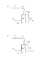
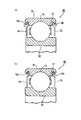
- (A) is principal part sectional drawing which shows the 1st example by which a press-fit introduction part is provided in the edge part of the axial direction end surface of a shield, and the outer peripheral surface, and the edge part of the axial direction end surface of an outer ring
- (b) is a cross-sectional view of a principal part showing a second example in which a press-fit introduction portion is provided at the edge between the axial end surface and the outer surface of the shield and the edge between the axial end surface of the outer ring and the large diameter portion.
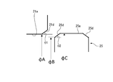
- Drawing 3 (a) it is a principal part enlarged view showing the dimensional relation of a press fit introduction part.
- It is principal part sectional drawing which shows the 3rd example by which a press-fit introduction part is provided in the edge part of the axial direction end surface of a shield, and the outer peripheral surface, and the edge part of the axial direction end surface of an outer ring
- It is principal part sectional drawing of the rolling bearing which concerns on 2nd embodiment of this invention.
- It is principal part sectional drawing of the conventional rolling bearing and is a figure explaining the method of mounting the conventional shield.
- FIG. 1 shows a cross-sectional view of a main part of a rolling bearing 20 according to the first embodiment of the present invention.
- the rolling bearing 20 includes an outer ring 21, an inner ring 22 that is an inner ring portion, a plurality of balls 23 that are rolling elements provided between the inner and outer rings, a cage 27 that holds the balls 23 in a freely rolling manner, and a flat plate shape.
- the outer ring 21 has inner diameters at both end portions in the axial direction that are larger in diameter than the inner diameter of the inner circumferential surface 21c of the outer ring 21 (in this embodiment, the inner circumferential surface of the shoulder portion) and open outward in the axial direction.
- a large-diameter portion 21a having an axial width wider than 25 axial widths (thicknesses) is provided.
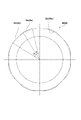
- the shield 25 has a thin plate shape like a flat washer having a constant thickness as shown in FIG.
- SPCC is plated with zinc, aluminum, and magnesium.
- the inner diameter of the shield 25 is a diameter that forms a labyrinth gap with the outer peripheral surface of the inner ring.
- the outer surface of the shield 25 includes a plurality of arcs 25a having the same central angle and equally arranged on the circumference, and a plurality of chords 25b respectively connecting the adjacent arcs 25a.
- the central angle ⁇ of each arc 25a is the same, and the central angle ⁇ of each chord 25b is the same, but the central angle ⁇ of the arc 25a and the central angle ⁇ of the chord 25b need to be the same. Absent.
- the central angle ⁇ of the chord 25b is larger than the central angle ⁇ of the arc 25a, the press-fit area for press-fitting into the large-diameter portion 21a of the outer ring 21 is reduced.
- deformation of the outer ring 21 can be suppressed to the extent that it does not affect the incorporation.
- the shield 25 is press-fitted and fixed so as to abut against the axially inner end face 21b of the large-diameter portion 21a. That is, the large-diameter portion 21a is for forming the axially inner end surface 21b for positioning the shield 25 in the axial direction, and has a minimum area of the axially inner end surface 21b that allows press-fitting positioning. Should just be provided. Since the shield 25 is formed symmetrically in the axial direction, it is not necessary to distinguish between the front surface and the back surface during press-fitting, and assembly is facilitated.
- the shield 25 is composed of a plurality of arcs 25a having the same central angle and equally arranged on the circumference, and a plurality of strings 25b respectively connecting the adjacent arcs 25a. Assembling is easy.
- the inscribed circle 25c of each string 25b of the shield 25 is preferably larger in diameter than the inner diameter of the inner peripheral surface 21c of the outer ring 21.
- the axially inner end surface 21b of the large diameter portion 21a is preferably a flat surface so that no gap is formed between the large diameter portion 21a and the shield 25.
- press-fitting is introduced into at least one of an edge portion between the axial end surface and the outer shape surface of the shield 25 and an edge portion between the axial end surface of the outer ring 21 and the large diameter portion 21a. It is preferable that the portions 21d and 25d are provided. As a result, when the shield 25 is press-fitted and fixed to the large-diameter portion 21a of the outer ring 21, the edge between the axial end surface of the shield 25 and the outer surface is scraped, foreign matter is generated, and the tightening margin is reduced to reduce the shield. It is possible to prevent 25 from falling off.
- a taper shape or a cross-section convex curved surface shape can be applied to the press-fit introduction portion 21d of the outer ring 21 and the press-fit introduction portion 25d of the shield 25, and any combination thereof may be used.
- the taper angles ⁇ 1 and ⁇ 2 are preferably 45 degrees or less (see FIG. 4).
- the press-fitting introduction part 21d of the outer ring 21 and the press-fitting introduction part 25d of the shield 25 may be tapered, or as shown in FIG.
- the press-fitting introduction part 21d of the outer ring 21 and the press-fitting introduction part 25d of the shield 25 may have a convex curved surface shape (R shape).
- the boundary between the large-diameter part 21a of the outer ring 21 and the press-fitting introduction part 21d are tapered, as shown in FIG. 4, the boundary between the large-diameter part 21a of the outer ring 21 and the press-fitting introduction part 21d.
- the diameter at the portion is ⁇ A
- the diameter at the boundary between the axial end face of the shield 25 and the press-fitting introduction portion 25d is ⁇ B
- the diameter of the arc 25a of the shield 25 is ⁇ C
- the dimensional relationship of ⁇ B ⁇ A ⁇ C is satisfied. From the viewpoint of ease of press-fitting and certainty of press-fitting.
- the press-fitting introduction part 21d of the outer ring 21 may be formed in a convex curved surface shape, and the press-fitting introduction part 25d of the shield 25 may be tapered. Since the shield 25 is thin, the tapered press-fitting introduction portion 25d is easy to process. Moreover, the press-fit introduction part 21d of the outer ring 21 having a convexly curved cross section can be easily processed by polishing, and the insertability of the shield 25 having the tapered press-fit introduction part 25d is good.
- the shield 25 since the press-fitting introduction portions 25d of the shield 25 are provided at both edge portions of the both axial end surfaces and the outer surface, the shield 25 does not need to be distinguished from the front surface and the back surface during press-fitting. It is more preferable from the viewpoint of ease.
- the chord 25b portion is also chamfered after being punched from one axial direction by a press.
- the press-fitting introduction portion 25d provided on the arc 25a is formed after the chamfering.
- the shield 25 shown in FIG. 2 is formed in an approximately octagon formed by eight arcs 25a and eight chords 25b.
- the shield 25 of the present invention is not limited to this, and six shields 25 are formed. What is necessary is just a substantially polygonal shape more than the substantially hexagon formed by the circular arc 25a and the six strings 25b.
- the outer diameter at the midpoint of the string 25b is smaller than the inner diameter of the inner peripheral surface 21c of the outer ring 21, and there is no gap between the string 25b and the inner peripheral surface of the outer ring 21. Desired. Therefore, as described above, the inscribed circle 25 c of each string 25 b of the shield 25 is preferably larger in diameter than the inner diameter of the inner peripheral surface 21 c of the outer ring 21.
- an appropriate press-fit area is obtained in a substantially hexagon formed by 16 arcs 25a and 16 strings 25b, and the inside of each string 25b of the shield 25 is
- the central angles ⁇ and ⁇ are set so that the contact circle 25 c has a larger diameter than the inner diameter of the inner peripheral surface 21 c of the outer ring 21.
- the center angle ⁇ of the arc 25a is set to 3.5 degrees
- the center angle ⁇ of the chord 25b is set to 19 degrees
- the sum of the center angles ⁇ and ⁇ of the arc 25a and the chord 25b is 22.2.
- the center angle ⁇ of the arc 25a is formed in the range of 2 to 7 degrees
- the center angle ⁇ of the chord 25 is formed in the range of 15 to 22 degrees.
- the press-fit margin is 2 ⁇ m
- the dimensional tolerance of the shield 25 is ⁇ 35 ⁇ m
- the dimensional tolerance of the large-diameter portion 21a of the outer ring 21 is ⁇ 25 ⁇ m. Therefore, the actual press-fit margin is 2 to 62 ⁇ m.
- the shield 25 may be press-fitted into the inner peripheral surface 21c of the outer ring 21 without providing the large-diameter portion 21a.
- the shields 25 are provided on both sides in the axial direction.
- the shield 25 may be provided only on one side in the axial direction.
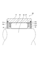
- FIG. 7 shows a cross-sectional view of the main part of the rolling bearing 30 according to the second embodiment of the present invention.
- the rolling bearing 30 includes an outer ring 31, a plurality of rollers 33 that are rolling elements, a cage 37 that holds the rollers 33 in a freely rolling manner, and a flat metal shield 35.
- the outer ring 31 has inner diameters at both ends in the axial direction that are larger in diameter than the inner diameter of the outer ring 31 and open outward in the axial direction, and have a larger axial width than the axial width (thickness) of the shield 35.
- a diameter portion 31a is provided.
- the shield 35 has a thin plate shape like a flat washer having a constant thickness as shown in FIG. 2, and the inner diameter is a diameter that forms a labyrinth gap with the outer peripheral surface of the support shaft 32 that is an inner ring portion.
- the outer surface of the shield 35 is composed of a plurality of arcs 35a having the same central angle and equally arranged on the circumference, and a plurality of chords 35b connecting the adjacent arcs 35a.
- the central angle ⁇ of each arc 35a is the same, and the central angle ⁇ of each chord 35b is the same, but the central angle ⁇ of the arc 35a and the central angle ⁇ of the chord need not be the same. .
- the central angle ⁇ of the chord 35b is larger than the central angle ⁇ of the arc 35a, the press-fitting area for press-fitting into the large-diameter portion 31a of the outer ring 31 is reduced.
- deformation of the outer ring 31 can be suppressed to the extent that it does not affect the incorporation.
- the shield 35 is press-fitted and fixed so as to abut against the axially inner end surface 31b of the large diameter portion 31a. That is, the large-diameter portion 31a is for forming the axially inner end surface 31b for positioning the shield 35, and has a minimum area of the axially inner end surface 31b that allows press-fitting positioning. Just do it.
- the inscribed circle 35c of each string 35b of the shield 35 is preferably larger in diameter than the inner diameter of the outer ring.
- the axially inner end surface 31b of the large diameter portion 31a is preferably a flat surface so that no gap is formed between the large diameter portion 31a and the shield 35.
- the shield 35 may be press-fitted into the outer ring inner peripheral surface 31c without providing the large-diameter portion 31a.
- the shields 35 are provided on both sides in the axial direction.
- the shield 35 may be provided only on one side in the axial direction.
- the bearing 30 of the present embodiment uses the outer peripheral surface of the support shaft 32 corresponding to the inner ring as a raceway surface, but may be a rolling bearing having an inner ring.
- the present invention is not limited to the above-described embodiment, and modifications, improvements, and the like can be made as appropriate.
- the outer surface of the shield is composed of a plurality of strings connecting a plurality of arcs and adjacent arcs, but a V-shaped notch may be used instead of the strings.
- the rolling bearing of the present invention can also be applied as a support bearing for a ball screw.
- a rolling bearing comprising an outer ring, an inner ring portion, a plurality of rolling elements, a cage for holding the plurality of rolling elements in a freely rolling manner, and a shield
- a large diameter portion having an axial width larger than the inner diameter of the outer ring and having an axial width wider than the axial width of the shield is provided on an inner peripheral surface of at least one axial end of the outer ring.
- the outer surface of the shield is composed of a plurality of arcs having the same central angle and equally arranged on the circumference, and a plurality of strings connecting the adjacent arcs, respectively.
- a press-fit introduction portion is provided on at least one of an edge portion between the axial end surface of the shield and the outer surface, and an edge portion between the axial end surface of the outer ring and the large diameter portion.
- the press-fitting introduction portion has a tapered shape or a convex curved surface shape in cross section.
- the tapered press-fitting introduction portion is formed on both the edge portion between the axial end surface of the shield and the outer shape surface, and the edge portion between the axial end surface of the outer ring and the large diameter portion,
- the diameter at the boundary between the large-diameter portion of the outer ring and the press-fit introduction portion is ⁇ A
- the diameter at the boundary between the axial end surface of the shield and the press-fit introduction portion is ⁇ B
- the diameter of the arc of the shield is ⁇ C.
- ⁇ B ⁇ A ⁇ C
- the press-fitting introduction portion having a convexly curved cross section is formed at the edge between the axial end surface of the outer ring and the large diameter portion
- the rolling bearing according to (3), wherein the press-fitting introduction portion having a tapered shape is formed at an edge portion between the axial end surface of the shield and the outer surface.
- the rolling bearing according to any one of (3) to (6), wherein the press-fitting introduction portions are provided at both edge portions of both end surfaces in the axial direction of the shield and the outer surface.
Landscapes
- Engineering & Computer Science (AREA)
- General Engineering & Computer Science (AREA)
- Mechanical Engineering (AREA)
- Rolling Contact Bearings (AREA)
Abstract
Priority Applications (4)
| Application Number | Priority Date | Filing Date | Title |
|---|---|---|---|
| JP2018527253A JP6376316B1 (ja) | 2017-02-23 | 2018-02-23 | 転がり軸受 |
| EP18757179.9A EP3421828B1 (fr) | 2017-02-23 | 2018-02-23 | Roulement à rouleaux |
| CN201880014325.1A CN110337550B (zh) | 2017-02-23 | 2018-02-23 | 滚动轴承 |
| US16/079,844 US10584742B2 (en) | 2017-02-23 | 2018-02-23 | Rolling bearing |
Applications Claiming Priority (2)
| Application Number | Priority Date | Filing Date | Title |
|---|---|---|---|
| JP2017031662 | 2017-02-23 | ||
| JP2017-031662 | 2017-02-23 |
Publications (1)
| Publication Number | Publication Date |
|---|---|
| WO2018155659A1 true WO2018155659A1 (fr) | 2018-08-30 |
Family
ID=63252807
Family Applications (1)
| Application Number | Title | Priority Date | Filing Date |
|---|---|---|---|
| PCT/JP2018/006824 WO2018155659A1 (fr) | 2017-02-23 | 2018-02-23 | Roulement à rouleaux |
Country Status (4)
| Country | Link |
|---|---|
| US (1) | US10584742B2 (fr) |
| EP (1) | EP3421828B1 (fr) |
| CN (1) | CN110337550B (fr) |
| WO (1) | WO2018155659A1 (fr) |
Cited By (1)
| Publication number | Priority date | Publication date | Assignee | Title |
|---|---|---|---|---|
| CN112780691A (zh) * | 2020-12-02 | 2021-05-11 | 陈新琴 | 一种平衡支撑轴承 |
Families Citing this family (1)
| Publication number | Priority date | Publication date | Assignee | Title |
|---|---|---|---|---|
| DE102021124846A1 (de) | 2021-09-27 | 2023-03-30 | Schaeffler Technologies AG & Co. KG | Lageranordnung für eine landwirtschaftliche Maschine |
Citations (6)
| Publication number | Priority date | Publication date | Assignee | Title |
|---|---|---|---|---|
| JPH07279979A (ja) | 1994-04-05 | 1995-10-27 | Koyo Seiko Co Ltd | 軸受の密封装置 |
| JPH112252A (ja) * | 1997-04-16 | 1999-01-06 | Nippon Seiko Kk | 密封板付転がり軸受 |
| JPH11351263A (ja) | 1998-06-05 | 1999-12-24 | Nippon Seiko Kk | 転がり軸受 |
| JP2001027253A (ja) | 1999-07-14 | 2001-01-30 | Nsk Ltd | 転がり軸受 |
| JP2008057635A (ja) * | 2006-08-30 | 2008-03-13 | Jtekt Corp | 転がり軸受用密封装置 |
| JP2017031662A (ja) | 2015-07-31 | 2017-02-09 | 玄 太田 | 散水消雪装置 |
Family Cites Families (20)
| Publication number | Priority date | Publication date | Assignee | Title |
|---|---|---|---|---|
| SE147456C1 (fr) * | ||||
| US2902300A (en) * | 1956-10-29 | 1959-09-01 | Marlin Rockwell Corp | Shield for rotatable members |
| US3597030A (en) * | 1969-04-22 | 1971-08-03 | Skf Svenska Kullagerfab Ab | Sealing device for rolling bearings |
| JPS58112733U (ja) * | 1982-01-26 | 1983-08-02 | エヌ・テ−・エヌ東洋ベアリング株式会社 | 転がり軸受用シ−ルド板 |
| JPH0473659U (fr) * | 1990-11-07 | 1992-06-29 | ||
| JPH06337016A (ja) * | 1993-05-28 | 1994-12-06 | Nippon Seiko Kk | 耐食性転がり軸受 |
| JPH08135667A (ja) * | 1994-11-14 | 1996-05-31 | Nippon Seiko Kk | 転がり軸受用密封装置 |
| US5470158A (en) * | 1994-12-29 | 1995-11-28 | The Torrington Company | Seal for rolling bearings |
| JPH08240228A (ja) * | 1995-03-06 | 1996-09-17 | Nippon Seiko Kk | 転がり軸受用密封装置 |
| US20020191877A1 (en) | 1997-04-16 | 2002-12-19 | Hironori Suzuki | Rolling bearing unit with shield plate |
| JP2990204B2 (ja) * | 1998-01-30 | 1999-12-13 | エスアイアイ・マイクロデバイス株式会社 | 転がり軸受、揺動アーム、回転体装置、転がり軸受の製造方法 |
| JPH11351264A (ja) * | 1998-06-04 | 1999-12-24 | Nok Corp | 密封装置 |
| JP3848825B2 (ja) * | 2000-09-14 | 2006-11-22 | 内山工業株式会社 | 軸受シールの装着構造 |
| US7287910B2 (en) * | 2001-09-03 | 2007-10-30 | Ntn Corporation | Angular ball bearing and rolling bearing |
| JP2003074491A (ja) * | 2001-09-04 | 2003-03-12 | Nsk Ltd | ウォータポンプ用シール装置とウォータポンプ用回転支持装置とウォータポンプ |
| US7431511B2 (en) * | 2003-02-18 | 2008-10-07 | Koyo Seiko Co., Ltd. | Rolling bearing |
| JP2011256966A (ja) * | 2010-06-10 | 2011-12-22 | Seiko Instruments Inc | 転がり軸受、軸受装置、情報記録再生装置 |
| JP6331754B2 (ja) * | 2013-07-09 | 2018-05-30 | 日本精工株式会社 | シールリング付玉軸受 |
| DE202014001654U1 (de) * | 2014-02-22 | 2015-05-26 | Oerlikon Leybold Vacuum Gmbh | Vakuumeinrichtung |
| CN204739098U (zh) * | 2015-06-23 | 2015-11-04 | 瓦房店爱国轴承研究院有限公司 | 一种由两个弹簧片组成真空密封腔的轴承密封结构 |
-
2018
- 2018-02-23 EP EP18757179.9A patent/EP3421828B1/fr active Active
- 2018-02-23 US US16/079,844 patent/US10584742B2/en active Active
- 2018-02-23 WO PCT/JP2018/006824 patent/WO2018155659A1/fr active Application Filing
- 2018-02-23 CN CN201880014325.1A patent/CN110337550B/zh active Active
Patent Citations (6)
| Publication number | Priority date | Publication date | Assignee | Title |
|---|---|---|---|---|
| JPH07279979A (ja) | 1994-04-05 | 1995-10-27 | Koyo Seiko Co Ltd | 軸受の密封装置 |
| JPH112252A (ja) * | 1997-04-16 | 1999-01-06 | Nippon Seiko Kk | 密封板付転がり軸受 |
| JPH11351263A (ja) | 1998-06-05 | 1999-12-24 | Nippon Seiko Kk | 転がり軸受 |
| JP2001027253A (ja) | 1999-07-14 | 2001-01-30 | Nsk Ltd | 転がり軸受 |
| JP2008057635A (ja) * | 2006-08-30 | 2008-03-13 | Jtekt Corp | 転がり軸受用密封装置 |
| JP2017031662A (ja) | 2015-07-31 | 2017-02-09 | 玄 太田 | 散水消雪装置 |
Cited By (2)
| Publication number | Priority date | Publication date | Assignee | Title |
|---|---|---|---|---|
| CN112780691A (zh) * | 2020-12-02 | 2021-05-11 | 陈新琴 | 一种平衡支撑轴承 |
| CN112780691B (zh) * | 2020-12-02 | 2022-10-21 | 河北天马轴承制造有限公司 | 一种平衡支撑轴承 |
Also Published As
| Publication number | Publication date |
|---|---|
| EP3421828B1 (fr) | 2020-01-22 |
| EP3421828A1 (fr) | 2019-01-02 |
| EP3421828A4 (fr) | 2019-05-01 |
| US10584742B2 (en) | 2020-03-10 |
| CN110337550A (zh) | 2019-10-15 |
| CN110337550B (zh) | 2020-11-24 |
| US20190360523A1 (en) | 2019-11-28 |
Similar Documents
| Publication | Publication Date | Title |
|---|---|---|
| KR101504810B1 (ko) | 스러스트 롤러 베어링 | |
| US9987880B2 (en) | Bearing assembly | |
| JP6569275B2 (ja) | 車輪用軸受装置の製造方法 | |
| EP1961981B1 (fr) | Dispositif de palier pour roue | |
| WO2018155659A1 (fr) | Roulement à rouleaux | |
| GB2296535A (en) | Seal for rolling bearings | |
| JP2007198540A (ja) | シール付き転がり軸受 | |
| JP6555426B2 (ja) | ハブユニット軸受およびその製造方法、並びに、自動車およびその製造方法 | |
| JP6376316B1 (ja) | 転がり軸受 | |
| WO2011036997A1 (fr) | Roulement à rouleaux coniques | |
| JP2017125617A (ja) | ころ軸受 | |
| JP2007309419A (ja) | 転がり軸受装置 | |
| JP7007924B2 (ja) | 車輪用軸受装置 | |
| WO2019117013A1 (fr) | Structure de fixation de palier à roulement | |
| JP2005069337A (ja) | シェル形ころ軸受 | |
| WO2014171405A1 (fr) | Palier a rouleaux coniques | |
| WO2018056000A1 (fr) | Dispositif de type palier pour essieu | |
| WO2024075316A1 (fr) | Cage, palier à roulement et procédé d'assemblage de palier à roulement | |
| JP7441609B2 (ja) | 車輪用軸受装置 | |
| WO2020179598A1 (fr) | Palier de butée | |
| WO2020225992A1 (fr) | Dispositif de palier de roue de véhicule | |
| WO2017014235A1 (fr) | Roulement à rouleaux cylindriques à deux rangées du type à rouleaux complémentaires | |
| JP2019044915A (ja) | 車輪用軸受装置 | |
| JP2017083012A (ja) | 車輪支持用複列転がり軸受ユニット | |
| JP6572693B2 (ja) | 転がり軸受用外輪 |
Legal Events
| Date | Code | Title | Description |
|---|---|---|---|
| ENP | Entry into the national phase |
Ref document number: 2018527253 Country of ref document: JP Kind code of ref document: A |
|
| WWE | Wipo information: entry into national phase |
Ref document number: 2018757179 Country of ref document: EP |
|
| ENP | Entry into the national phase |
Ref document number: 2018757179 Country of ref document: EP Effective date: 20180926 |
|
| 121 | Ep: the epo has been informed by wipo that ep was designated in this application |
Ref document number: 18757179 Country of ref document: EP Kind code of ref document: A1 |
|
| NENP | Non-entry into the national phase |
Ref country code: DE |