WO2018147126A1 - n型導電材料およびその製造方法 - Google Patents
n型導電材料およびその製造方法 Download PDFInfo
- Publication number
- WO2018147126A1 WO2018147126A1 PCT/JP2018/002877 JP2018002877W WO2018147126A1 WO 2018147126 A1 WO2018147126 A1 WO 2018147126A1 JP 2018002877 W JP2018002877 W JP 2018002877W WO 2018147126 A1 WO2018147126 A1 WO 2018147126A1
- Authority
- WO
- WIPO (PCT)
- Prior art keywords
- conductive material
- type
- carbon nanotube
- type conductive
- metal complex
- Prior art date
- Legal status (The legal status is an assumption and is not a legal conclusion. Google has not performed a legal analysis and makes no representation as to the accuracy of the status listed.)
- Ceased
Links
Images


Classifications
-
- H—ELECTRICITY
- H10—SEMICONDUCTOR DEVICES; ELECTRIC SOLID-STATE DEVICES NOT OTHERWISE PROVIDED FOR
- H10N—ELECTRIC SOLID-STATE DEVICES NOT OTHERWISE PROVIDED FOR
- H10N10/00—Thermoelectric devices comprising a junction of dissimilar materials, i.e. devices exhibiting Seebeck or Peltier effects
- H10N10/80—Constructional details
- H10N10/85—Thermoelectric active materials
- H10N10/851—Thermoelectric active materials comprising inorganic compositions
- H10N10/855—Thermoelectric active materials comprising inorganic compositions comprising compounds containing boron, carbon, oxygen or nitrogen
-
- B—PERFORMING OPERATIONS; TRANSPORTING
- B82—NANOTECHNOLOGY
- B82Y—SPECIFIC USES OR APPLICATIONS OF NANOSTRUCTURES; MEASUREMENT OR ANALYSIS OF NANOSTRUCTURES; MANUFACTURE OR TREATMENT OF NANOSTRUCTURES
- B82Y30/00—Nanotechnology for materials or surface science, e.g. nanocomposites
-
- B—PERFORMING OPERATIONS; TRANSPORTING
- B82—NANOTECHNOLOGY
- B82Y—SPECIFIC USES OR APPLICATIONS OF NANOSTRUCTURES; MEASUREMENT OR ANALYSIS OF NANOSTRUCTURES; MANUFACTURE OR TREATMENT OF NANOSTRUCTURES
- B82Y40/00—Manufacture or treatment of nanostructures
-
- C—CHEMISTRY; METALLURGY
- C01—INORGANIC CHEMISTRY
- C01B—NON-METALLIC ELEMENTS; COMPOUNDS THEREOF; METALLOIDS OR COMPOUNDS THEREOF NOT COVERED BY SUBCLASS C01C
- C01B32/00—Carbon; Compounds thereof
- C01B32/15—Nano-sized carbon materials
- C01B32/158—Carbon nanotubes
-
- H—ELECTRICITY
- H10—SEMICONDUCTOR DEVICES; ELECTRIC SOLID-STATE DEVICES NOT OTHERWISE PROVIDED FOR
- H10D—INORGANIC ELECTRIC SEMICONDUCTOR DEVICES
- H10D62/00—Semiconductor bodies, or regions thereof, of devices having potential barriers
- H10D62/10—Shapes, relative sizes or dispositions of the regions of the semiconductor bodies; Shapes of the semiconductor bodies
-
- H—ELECTRICITY
- H10—SEMICONDUCTOR DEVICES; ELECTRIC SOLID-STATE DEVICES NOT OTHERWISE PROVIDED FOR
- H10K—ORGANIC ELECTRIC SOLID-STATE DEVICES
- H10K85/00—Organic materials used in the body or electrodes of devices covered by this subclass
- H10K85/30—Coordination compounds
-
- H—ELECTRICITY
- H10—SEMICONDUCTOR DEVICES; ELECTRIC SOLID-STATE DEVICES NOT OTHERWISE PROVIDED FOR
- H10N—ELECTRIC SOLID-STATE DEVICES NOT OTHERWISE PROVIDED FOR
- H10N10/00—Thermoelectric devices comprising a junction of dissimilar materials, i.e. devices exhibiting Seebeck or Peltier effects
- H10N10/01—Manufacture or treatment
Definitions
- the present invention relates to an n-type conductive material and a manufacturing method thereof.
- thermoelectric conversion materials have attracted attention as one of CO 2 -free power generation technologies that obtain power from natural renewable energy or exhaust heat.
- thermoelectric conversion material for use as an emergency, disaster or medical power source.
- the thermoelectric conversion material is closely_contact
- organic materials containing conductive polymers or nanomaterials such as carbon nanotubes have attracted attention.
- organic-based or carbon-based thermoelectric conversion materials are considered to be element materials that are portable and flexible thermoelectric conversion device candidates because of their light weight and the flexibility of structures derived from carbon-carbon bonds. Yes.
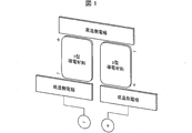
- FIG. 1 is a schematic diagram illustrating an example of a bipolar thermoelectric conversion device including an n-type conductive material and a p-type conductive material.
- a bipolar thermoelectric conversion device can efficiently generate power by connecting an n-type conductive material and a p-type conductive material in series.
- thermoelectric conversion materials examples include the following technologies.
- Patent Document 1 discloses a thermoelectric conversion material containing a conductive polymer and a thermal excitation assist agent.
- Patent Document 2 discloses a thermoelectric conversion material containing a carbon nanotube and a conjugated polymer.
- Non-Patent Document 1 describes a conductive film using poly (3,4-ethylenedioxythiophene) (PEDOT).
- Non-Patent Document 2 describes a composite material using a composite of PEDOT and poly (styrenesulfonic acid) (PEDOT: PSS) or meso-tetra (4-carboxyphenyl) porphine (TCPP) and carbon nanotubes. ing.
- Non-Patent Documents 1 and 2 are p-type conductive materials as can be seen from the fact that the Seebeck coefficient is a positive value.
- the n-type conductive material as described in Non-Patent Document 3, the n-type organic material, the n-type carbon material, or the additive inherently has an unstable chemical bond, and the stable n-type. It was common technical knowledge in the field that it was difficult to obtain a conductive material. Under such circumstances, the present inventors have developed, for example, a technique described in Patent Document 3 as a technique for converting a p-type conductive material into an n-type conductive material.
- the present invention has been made in view of the above problems, and an object thereof is to provide an n-type conductive material having excellent thermoelectric properties and chemical stability.
- an n-type conductive material having excellent thermoelectric properties and chemical stability can be provided by encapsulating a metal complex in an n-type carbon nanotube.
- the present invention has been completed.
- the present invention includes the inventions described in [1] to [6] below.
- An n-type conductive material comprising an n-type carbon nanotube encapsulating a metal complex.
- a method for producing an n-type conductive material comprising a vacuum heating step of heating an n-type carbon nanotube brought into contact with a metal complex at 100 ° C.
- n-type carbon nanotubes can provide an n-type conductive material having excellent thermoelectric properties and chemical stability by encapsulating a metal complex.
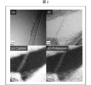
- FIG. 1 is a figure which shows the transmission electron microscope image of the carbon nanotube in the comparative example 1.
- FIG. (B) is a view showing a transmission electron microscope image of the carbon nanotube in Example 1.
- FIG. (C) and (d) is a figure which shows the result of having observed the presence or absence of carbon and potassium inside the carbon nanotube of Example 1, respectively by elemental analysis.
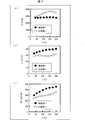
- (A) to (c) are diagrams showing measured values of conductivity, measured values of Seebeck coefficient, and calculated values of output factors of Example 1 and Comparative Example 1 at 37 ° C. to 200 ° C., respectively.
- (A) to (c) are diagrams showing measured values of conductivity, measured values of Seebeck coefficient, and calculated values of output factors in Example 2 and Comparative Example 2 at 37 ° C. to 200 ° C., respectively. It is a figure which shows the change of Seebeck coefficient in 37 degreeC of Example 1 and the comparative example 1 accompanying ethanol washing
- index of performance of n-type conductive materials First, an index relating to the performance of the n-type conductive material will be described. An example of the index is an output factor (power factor). The output factor is obtained by the following equation (1).
- PF ⁇ 2 ⁇ (1)
- PF is an output factor
- ⁇ is a Seebeck coefficient
- ⁇ is conductivity.
- the output factor is 100 .mu.W / mK 2 or more at 310K, more preferably 200 ⁇ W / mK 2 or more, and particularly preferably 400 W / mK 2 or more. If the output factor is 100 ⁇ W / mK 2 or more at 310K, it is preferable because it is equal to or higher than that of a conventional p-type conductive material. In order to obtain such a high-output n-type conductive material, it is conceivable to improve either the Seebeck coefficient or the conductivity, or both.
- the Seebeck coefficient is the ratio of the open circuit voltage to the temperature difference between the high-temperature junction and the low-temperature junction of the circuit showing the Seebeck effect (from “Maglow Hill Science and Technology Terms Dictionary 3rd edition”).
- the Seebeck coefficient can be measured using, for example, a Seebeck effect measuring apparatus (manufactured by MMR Technologies) used in Examples described later. The larger the absolute value of the Seebeck coefficient, the greater the thermoelectromotive force.
- the Seebeck coefficient can be an index for discriminating the polarity of an electronic material such as a carbon nanotube. Specifically, for example, it can be said that an electronic material having a positive Seebeck coefficient has p-type conductivity. In contrast, an electronic material having a negative Seebeck coefficient can be said to have n-type conductivity.
- the Seebeck coefficient is preferably ⁇ 20 ⁇ V / K or less, more preferably ⁇ 30 ⁇ V / K or less, and further preferably ⁇ 40 ⁇ V / K or less.
- the Seebeck coefficient is more preferably ⁇ 40 to ⁇ 20 ⁇ V / K.
- the conductivity can be measured, for example, by a four-probe method using a resistivity meter (Made by Mitsubishi Chemical Analytech, Loresta GP).
- the conductivity is preferably 1000 S / cm or more, more preferably 1500 S / cm or more, and further preferably 2000 S / cm or more.
- a conductivity of 1000 S / cm or more is preferable because the n-type conductive material has a high output.
- ZT is calculated
- ZT PF ⁇ T / ⁇ (2)
- T is temperature
- ⁇ thermal conductivity.
- thermoelectric conversion material that is, the n-type conductive material and the p-type conductive material
- thermoelectric conversion material using a temperature difference.
- the thermal conductivity of the thermoelectric conversion material is large, the temperature in the substance becomes easily uniform, and a temperature difference is hardly generated. Therefore, a thermoelectric conversion device including a thermoelectric conversion material having a high thermal conductivity tends to be difficult to generate power efficiently.
- An n-type conductive material according to an embodiment of the present invention includes an n-type carbon nanotube encapsulating a metal complex.
- encapsulating a metal complex means that the metal complex is located inside the cavity of the carbon nanotube.
- whether or not the metal complex is encapsulated in the carbon nanotube can be examined by, for example, observing with a transmission electron microscope as shown in Examples described later.
- the n-type carbon nanotube has a negative charge delocalized and is a soft base.
- the metal complex is a soft acid with a positive charge delocalized.
- a soft base can be stabilized by the action of a soft acid. Therefore, this n-type conductive material exhibits stable n-type conductivity by allowing a metal complex to act on n-type carbon nanotubes.
- the definitions of soft acids and bases are based on HSAB theory (R. G. Pearson, J. Am. Chem. Soc. 85 (22), 3533-3539, 1963).
- the n-type conductive material has excellent thermoelectric properties and chemical stability because the metal complex is encapsulated in the n-type carbon nanotube. This is presumed to be because when the metal complex is encapsulated in the n-type carbon nanotube, the metal complex is less likely to be detached than when the metal complex is simply attached to the surface of the n-type carbon nanotube.
- the present n-type conductive material may contain substances other than n-type carbon nanotubes and metal complexes as necessary. Such a substance is not particularly limited as long as it is a substance that does not inhibit the above-described effect of the metal complex.
- the present n-type conductive material includes n-type carbon nanotubes.
- the n-type carbon nanotube only needs to have n-type conductivity, and may be made n-type by any method.
- the carbon nanotube may be referred to as “CNT”.
- the carbon nanotube may have a single-layer structure or a multi-layer structure (that is, a two-layer, three-layer, four-layer, or more than that).
- the carbon nanotube may be a single-walled carbon nanotube (SWNT) or a multi-walled carbon nanotube (MWNT).
- thermoelectric conversion device can be used in various applications and applications as a thermoelectric conversion device.
- the thermoelectric conversion device has flexibility because it can be brought into close contact with a complicated three-dimensional surface such as a human body and piping, and body temperature and waste heat can be used efficiently.
- a single-walled carbon nanotube is preferable.
- the average inner diameter of the n-type carbon nanotube is not particularly limited, and is preferably, for example, 0.6 to 1000 nm, more preferably 0.6 to 100 nm, and further preferably 0.8 to 20 nm. 1 to 5 nm is particularly preferable, and 1.2 to 3 nm is most preferable.
- the average inner diameter is 0.6 nm or more, the metal complex can be sufficiently taken into the n-type carbon nanotube.
- the average inner diameter is 1.2 nm or more because the metal complex can easily enter the inside of the n-type carbon nanotube.
- an average internal diameter is 1000 nm or less, since diffusion of a metal complex is suppressed inside an n-type carbon nanotube and chemical stability will be obtained at normal pressure and normal temperature, it is preferable. Furthermore, if the average inner diameter is 3 nm or less, the metal complex is hardly detached from the inside of the n-type carbon nanotube, and in some aspects, excellent thermoelectric conversion characteristics are obtained, which is more preferable.
- the average inner diameter of the n-type carbon nanotube is measured by observing the n-type carbon nanotube with a transmission electron microscope or a scanning electron microscope. An arbitrary five places of the n-type conductive material are observed with a transmission electron microscope or a scanning electron microscope. Ten n-type carbon nanotubes are randomly selected per place, the inner diameter of each is measured, and the average value of the measured inner diameters of the 50 n-type carbon nanotubes is taken as the average inner diameter of the n-type carbon nanotubes.
- the carbon nanotube may be formed into a desired shape.
- the n-type conductive material may include a film in which carbon nanotubes are integrated.
- the “film” is also referred to as a sheet or a membrane.
- the film may have a thickness of 1 ⁇ m to 1000 ⁇ m, for example.
- the density of the carbon nanotubes in the film is not particularly limited, but may be 0.05 to 1.0 g / cm 3 or 0.1 to 0.5 g / cm 3 .
- the film has a non-woven structure so that the carbon nanotubes are intertwined with each other. Therefore, the film is lightweight and has flexibility.
- This n-type conductive material contains a metal complex.
- a metal complex intends a molecule in which a metal cation is coordinated to a ligand.
- metal cations include typical metal ions (alkali metal ions and alkaline earth metal ions) and transition metal ions.
- the metal cation may be, for example, lithium ion, sodium ion, potassium ion, rubidium ion, cesium ion, francium ion, beryllium ion, magnesium ion, calcium ion, strontium ion, barium ion, radium ion and scandium ion. Good.
- the ligand is not particularly limited as long as it is a compound that forms a coordinate bond with a metal cation.
- the ligand is a compound having a coordination unit for a metal cation.
- the ligand include organic ligands.
- the organic ligand may be a monodentate organic ligand (ie, a compound having one coordination unit), or a multidentate organic ligand (ie, a compound having two or more coordination units) ).
- the organic ligand is preferably a multidentate organic ligand from the viewpoint that a metal cation can be incorporated more efficiently.
- the multidentate organic ligand examples include cyclodextrin, crown ether and derivatives thereof (for example, benzocrown ether and dibenzocrown ether), calixarene and derivatives thereof, and the like. Especially, it is preferable to use a crown ether and its derivative in an organic solvent, and a crown ether derivative is more preferable. Crown ether can solvate cations through unshared electron pairs on oxygen.
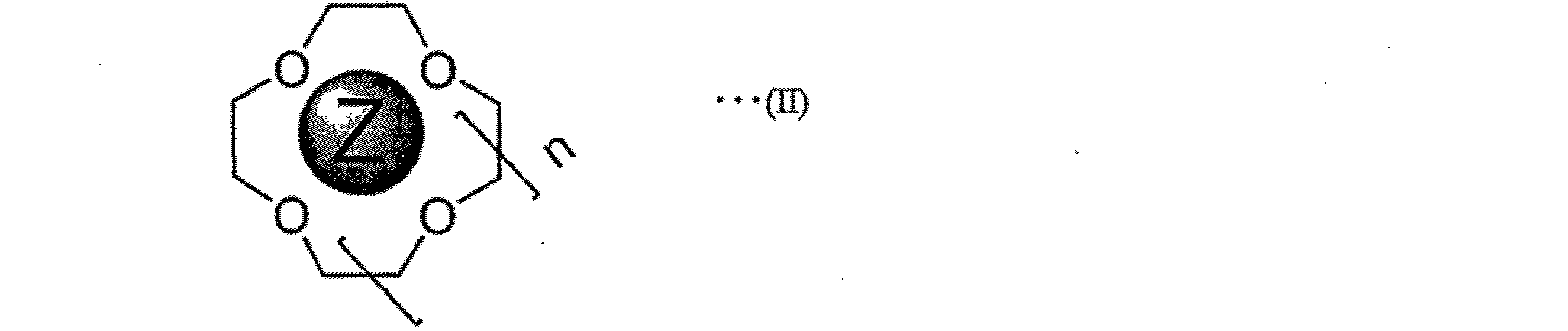
- crown ethers represented by the following general formula (I).
- n is an integer of 1 or more.
- n is an integer of 1 or more.
- Z is the metal cation described above.
- crown ethers represented by the following formulas (a) to (c).
- the above formula (a) is 12-crown-4-ether.
- the above formula (b) is 15-crown-5-ether.
- the above formula (c) is 18-crown-6-ether.
- crown ether derivative examples include compounds having one or more aryl rings.
- the crown ether derivative is more delocalized in charge with the expansion of the aryl ring portion than the crown ether. Therefore, when using a crown ether derivative having one or more aryl rings, it exhibits more stable n-type conductivity and higher conductivity and chemical stability than when using a crown ether having no aryl ring. Showing gender.
- the one or more aryl rings preferably form a condensed ring. That is, the crown ether derivative is preferably a crown ether derivative having a condensed ring.
- the fused ring may be a group in which 2, 3, 4, 5, or more aryl rings are fused.
- aryl ring or condensed ring examples include a benzene ring, naphthalene ring, anthracene ring, tetracene ring, pentacene ring, hexacene ring, heptacene ring, octacene ring, phenanthrene ring, pyrene ring, chrysene ring, benzopyrene ring, triphenylene ring, Or a benzofuran ring is mentioned.
- crown ether derivative having a benzene ring examples include benzo-18-crown-6 represented by the following formula (d).
- the crown ether and derivatives thereof may be selected according to the size of the metal cation to be incorporated.
- a method for producing an n-type conductive material according to an embodiment of the present invention (hereinafter also referred to as this production method) is a vacuum in which n-type carbon nanotubes brought into contact with a metal complex are heated at 100 ° C. or higher under vacuum conditions. Including a heating step. According to this production method, the metal complex is encapsulated in the n-type carbon nanotube. Therefore, an n-type conductive material having excellent thermoelectric properties and chemical stability can be obtained.
- This step is a step of heating the n-type carbon nanotube brought into contact with the metal complex at 100 ° C. or higher under vacuum conditions. By performing this step, the metal complex is encapsulated in the n-type carbon nanotube.
- Examples of the method of bringing the carbon nanotube into contact with the metal complex include a method of bringing a solution containing the metal complex into contact with the carbon nanotube.
- the method for bringing the solution containing the metal complex into contact with the carbon nanotubes is not particularly limited as long as the carbon nanotubes and the solution can be brought into contact with each other. From the viewpoint of sufficiently bringing the carbon nanotubes into contact with the solution, it is preferable to bring the carbon nanotubes into contact with the solution by impregnating the carbon nanotubes with the solution or by shearing and dispersing the carbon nanotubes in the solution.
- Examples of the method for impregnating the carbon nanotube with the solution include a method in which a carbon nanotube (for example, a film) molded into a desired shape is immersed in the solution as described later.
- a method of shearing and dispersing the carbon nanotubes in the solution a method of dispersing the carbon nanotubes in the solution using a homogenizer can be mentioned.
- the solvent in the above solution may be water or an organic solvent.
- the solvent is preferably an organic solvent, more preferably methanol, ethanol, propanol, butanol, acetonitrile, N, N-dimethylformamide, dimethyl sulfoxide or N-methylpyrrolidone.
- Propanol includes 1-propanol and 2-propanol. Examples of butanol include 1-butanol and 2-butanol.
- the concentration of the metal complex in the solution may be any concentration, for example, preferably 0.001 to 1 mol / L, and more preferably 0.01 to 0.1 mol / L.
- the homogenizer is not particularly limited as long as it can uniformly disperse carbon nanotubes in a solution.
- known means such as a homogenizer or an ultrasonic homogenizer can be used.
- homogenizer when it only describes with “homogenizer”, “stirring homogenizer” is intended.
- the operating conditions of the homogenizer are not particularly limited as long as the carbon nanotubes can be dispersed in the solution.
- the carbon nanotubes are treated by treating the solution added with the carbon nanotubes at a homogenizer stirring speed (rotation speed) of 20000 rpm at room temperature (23 ° C.) for 10 minutes. It can be dispersed in a solution.
- the immersion time is not particularly limited, but is preferably 10 to 600 minutes, more preferably 100 to 600 minutes, and more preferably 200 to 600 minutes. More preferably.
- n-type method is not particularly limited, and examples thereof include a method of introducing electrons from the electrode into the carbon nanotube and a method of causing a specific anion to act on the carbon nanotube.
- the step of converting the carbon nanotube into n-type may be performed simultaneously with this step.
- the carbon nanotube is brought into contact with a solution in which a metal salt that generates an anion and a metal cation included in the metal complex when dissolved in a solvent and a ligand are dissolved, and this step is performed.
- the solution preferably contains a metal cation and a ligand so that the molar ratio thereof is 1: 1.
- the above anions change the carbon nanotube carrier from holes to electrons. As a result, the Seebeck coefficient of the carbon nanotube changes and the carbon nanotube is negatively charged.
- anions examples include hydroxy ions (OH ⁇ ), alkoxy ions (CH 3 O ⁇ , CH 3 CH 2 O ⁇ , i-PrO ⁇ and t-BuO ⁇ etc.), thio ions (SH ⁇ , and CH 3 S ⁇ ). And alkylthio ions such as C 2 H 5 S ⁇ ), cyanuric ions (CN ⁇ ), I ⁇ , Br ⁇ , Cl ⁇ , BH 4 ⁇ , carboxy ions (CH 3 COO ⁇ and the like), NO 3 ⁇ , BF 4 -, ClO 4 -, TfO - , and Tos -, and the like.
- anions include OH ⁇ , CH 3 O ⁇ , CH 3 CH 3 O ⁇ , i-PrO ⁇ , t-BuO ⁇ , SH ⁇ , CH 3 S ⁇ , C 2 H 5 S ⁇ , CN ⁇ , I -, Br -, Cl -, BH 4 -, and CH 3 COO - is preferably at least one selected from the group consisting of, OH - and CH 3 O - and more preferably at least one of . According to the anion, the Seebeck coefficient of the carbon nanotube can be changed efficiently.
- the anion acts as a dopant for converting the carbon nanotube to n-type may be that the anion has an unshared electron pair.
- An anion is presumed to interact with the carbon nanotube to be doped or to induce a chemical reaction based on its unshared electron pair.
- the Lewis basicity, intermolecular force, and dissociation properties of the dopant are considered to be important in doping efficiency.
- Lewis basic means the property of donating an electron pair. It is considered that a dopant having strong Lewis basicity has a greater influence on the change in Seebeck coefficient.
- the intermolecular force of the dopant is considered to be related to the adsorptivity of the dopant to the carbon nanotube.
- the intermolecular force of the dopant include hydrogen bonding, CH- ⁇ interaction, and ⁇ - ⁇ interaction.
- an anion that gives a weak hydrogen bond is preferable.
- the anion that gives a weak hydrogen bond include OH ⁇ , CH 3 O ⁇ , CH 3 CH 2 O ⁇ , i-PrO ⁇ , and t-BuO ⁇ .
- the anion is preferably an anion that gives a ⁇ - ⁇ interaction. Examples of the anion to give [pi-[pi interactions, for example, CH 3 COO - and the like.
- the vacuum condition is 100 Pa or less. Under vacuum conditions, the pressure is preferably 0.01 Pa to 50 Pa, more preferably 0.1 Pa to 20 Pa, and further preferably 1 Pa to 10 Pa.
- the temperature at which the vacuum heating is performed may be appropriately determined in consideration of the sublimation point or melting point of the metal complex, preferably 100 ° C. or higher, more preferably 120 ° C. to 250 ° C., and still more preferably 180 ° C. to 250 ° C.
- the time for heating under vacuum conditions is not particularly limited, but is preferably 2 hours or more, more preferably 3 hours to 72 hours, and even more preferably 10 hours to 20 hours.
- At least one of the pressure, temperature, and time is in the above range because the metal complex can be more efficiently encapsulated in the n-type carbon nanotube.
- the manufacturing method may include a forming step before or after the vacuum heating step. That is, this step may be a step of forming the carbon nanotube into a desired shape (for example, a film) before the vacuum heating step, and the n-type conductive material obtained by the vacuum heating step is formed into a desired shape. It may be a step of molding.
- the present manufacturing method includes a forming step of forming a film by accumulating carbon nanotubes before the vacuum heating step.
- a forming step of forming a film by accumulating carbon nanotubes before the vacuum heating step.
- the method of forming the film is not particularly limited, and examples thereof include a method of forming a film by dispersing carbon nanotubes in a solvent and filtering the obtained dispersion on a filter.
- a method using a membrane filter can be used. Specifically, the carbon nanotube dispersion liquid is subjected to suction filtration using a membrane filter having a pore size of 0.1 to 2 ⁇ m, and the membrane remaining on the membrane filter is subjected to 50 to 150 ° C. for 1 to 24 hours.
- the film can be formed by drying under reduced pressure.
- the solvent for dispersing the carbon nanotubes may be water or an organic solvent.
- the solvent is preferably an organic solvent, and more preferably o-dichlorobenzene, bromobenzene, 1-chloronaphthalene, 2-chloronaphthalene or cyclohexanone. With these solvents, the carbon nanotubes can be efficiently dispersed.
- the above ⁇ 3-1 As a method for dispersing the carbon nanotubes, the above ⁇ 3-1. A method similar to the method of dispersing the carbon nanotubes in the solution using the homogenizer in the vacuum heating step> can be used.
- Example 1 5 mg of CNT (average inner diameter 2 nm, Meijo Nanocarbon Co., Ltd., product name: EC2.0) was treated with 10 mL of o-dichlorobenzene for 10 minutes at 20000 rpm using a stirring homogenizer (IKA, Ultra Tarrax). did. Thereafter, the obtained solution was suction filtered on a membrane filter (0.2 mm pore diameter, 25 mm diameter), and then dried at 120 ° C. under reduced pressure for 12 hours to obtain a CNT film.
- a stirring homogenizer IKA, Ultra Tarrax
- Example 1 After pulling up the CNT film from the solution, the CNT film was subjected to vacuum heating at 200 ° C. for 3 hours to obtain an n-type conductive material of Example 1.
- Comparative Example 1 After pulling up the CNT film from the solution, an n-type conductive material of Comparative Example 1 was obtained in the same manner as in Example 1 except that the CNT film was vacuum heated at 80 ° C. for 1 hour.
- Example 2 An n-type conductive material of Example 2 was obtained in the same manner as in Example 1 except that 18-crown ether (manufactured by Sigma-Aldrich) was used instead of benzo-18-crown ether.
- 18-crown ether manufactured by Sigma-Aldrich
- Comparative Example 2 After pulling up the CNT film from the solution, an n-type conductive material of Comparative Example 2 was obtained in the same manner as in Example 2, except that the CNT film was vacuum heated at 80 ° C. for 1 hour.
- Comparative Example 3 A CNT film obtained in the same manner as in Example 1 was used as Comparative Example 3 without being immersed in the solution.
- Example 1 [Observation with a transmission electron microscope] The n-type conductive material of Example 1 and Comparative Example 1 was observed with a transmission electron microscope (manufactured by JEOL, product name: JEM-3100FEF).
- FIG. 2 (a) is a view showing a transmission electron microscope image of the carbon nanotube in Comparative Example 1.
- FIG. FIG. 2B is a view showing a transmission electron microscope image of the carbon nanotubes in Example 1.
- FIG. 2A the metal complex is located outside the carbon nanotube, whereas in FIG. 2B, the metal complex is located inside the carbon nanotube.
- 2 (c) and 2 (d) are views showing the results of observing the presence or absence of carbon and potassium inside the carbon nanotube of Example 1 by elemental analysis. Electron energy loss spectroscopy was used for elemental analysis. 2 (c) and (d), it was found that carbon and potassium were present inside the carbon nanotube of Example 1. Therefore, it can be seen from FIGS. 2C and 2D that in Example 1, the metal complex is included in the carbon nanotubes.
- thermoelectric properties For the n-type conductive materials obtained in the examples and comparative examples, the conductivity ⁇ and Seebeck coefficient ⁇ at 37 ° C. to 200 ° C. using a thermoelectric property evaluation apparatus (manufactured by Advance Riko Co., Ltd., product name: ZEM-3). was measured. The conductivity was measured by the four probe method, and the Seebeck coefficient was measured by the two probe method. Further, the output factor PF was calculated by the above formula (1) using the obtained conductivity and Seebeck coefficient.
- FIGS. 3A to 3C are diagrams showing measured values of conductivity, measured values of Seebeck coefficient, and calculated values of output factors in Example 1 and Comparative Example 1 at 37 ° C. to 200 ° C., respectively. .
- the horizontal axis represents the measured temperature.
- the measured values of Example 1 are indicated by black circles, and the measured values of Comparative Example 1 are indicated by white circles.
- the conductivity of the n-type conductive material of Comparative Example 1 changes depending on the temperature, while the n-type conductive material of Example 1 changes to the temperature. It can be seen that stable conductivity is exhibited without dependence.
- Example 1 shows that the absolute value of the Seebeck coefficient is larger than that of Comparative Example 1 at any temperature, so that the thermoelectromotive force is large at any temperature.
- the n-type conductive material of Example 1 shows a higher output factor at any temperature of 37 ° C. to 200 ° C. than the n-type conductive material of Comparative Example 1. Recognize. From this, it can be seen that the power factor increases when the metal complex is encapsulated in the carbon nanotube.
- FIGS. 4A to 4C are diagrams showing measured values of conductivity, measured values of Seebeck coefficient, and calculated values of output factors in Example 2 and Comparative Example 2 at 37 ° C. to 200 ° C.
- FIG. The horizontal axis represents the measured temperature.
- the measurement values of Example 2 are indicated by black circles, and the measurement values of Comparative Example 2 are indicated by white circles.
- the conductivity of the n-type conductive material of Comparative Example 2 changes depending on the temperature, while the n-type conductive material of Example 2 varies with temperature. It can be seen that stable conductivity is exhibited without dependence.
- Example 2 has a larger Seebeck coefficient than Comparative Example 2 at any temperature, indicating that the thermoelectromotive force is large at any temperature.
- the n-type conductive material of Example 2 shows a higher output factor at any temperature of 37 ° C. to 200 ° C. than the n-type conductive material of Comparative Example 2. Recognize.
- Example 2 Comparative Example 2
- the output factor increases when the metal complex is encapsulated in the carbon nanotube.
- the ligand having a benzene ring exhibits more stable n-type conductivity and a higher output factor. I understand.
- the thermal diffusivity, the constant pressure specific heat, the density and the thermal conductivity of the n-type conductive material obtained in Example 1 and Comparative Example 1 and the CNT film obtained in Comparative Example 3 were measured.
- the thermal diffusivity in the in-plane direction was measured using a flash analyzer (product name: LFA 467 HyperFlash, manufactured by Netch Co., Ltd.).
- the constant-pressure specific heat was measured using a differential scanning calorimeter (product name: DSC6200, manufactured by SII Nano Technology).
- the thermal conductivity was calculated from the product of the obtained thermal diffusivity, constant pressure specific heat and density.
- Table 1 shows the measurement results.
- Example 1 and Comparative Example 1 both have a thermal conductivity of 38 W / m ⁇ K. And as above-mentioned, in Example 1, an output factor increases compared with the comparative example 1. FIG. Therefore, in Example 1, it turns out that ZT can be increased by the increase of an output factor.
- FIG. 5 is a graph showing changes in Seebeck coefficient at 37 ° C. in Example 1 and Comparative Example 1 accompanying ethanol cleaning.
- the horizontal axis indicates the processing time for ethanol cleaning.
- the measured value of Example 1 is shown by a black circle
- the measured value of Comparative Example 1 is shown by a white circle.
- Comparative Example 1 In the n-type conductive material of Comparative Example 1, the Seebeck coefficient changed from a negative value to a positive value during ethanol cleaning for 600 to 700 seconds. From this, it can be seen that Comparative Example 1 lost the n-type conductivity by the ethanol cleaning. In Comparative Example 1, since the metal complex is not encapsulated in the carbon nanotube, it is considered that the metal complex adsorbed on the surface of the carbon nanotube was desorbed by washing with ethanol.
- Example 1 the Seebeck coefficient shows a negative value even in ethanol cleaning for 1000 seconds. From this, it can be seen that Example 1 has n-type conductivity stably even after ethanol washing. In Example 1, since the metal complex is encapsulated in the carbon nanotubes, it is considered that the metal complex can continue to be encapsulated without being detached even by ethanol washing. That is, it is considered that the chemical stability is improved by encapsulating the metal complex in the carbon nanotube.
- the present invention can be used in a wide variety of industries such as thermoelectric power generation systems, medical power supplies, security power supplies, and aerospace applications.
Landscapes
- Chemical & Material Sciences (AREA)
- Engineering & Computer Science (AREA)
- Nanotechnology (AREA)
- Materials Engineering (AREA)
- Inorganic Chemistry (AREA)
- Organic Chemistry (AREA)
- Physics & Mathematics (AREA)
- Condensed Matter Physics & Semiconductors (AREA)
- General Physics & Mathematics (AREA)
- Crystallography & Structural Chemistry (AREA)
- Manufacturing & Machinery (AREA)
- Composite Materials (AREA)
- Carbon And Carbon Compounds (AREA)
Abstract
Description
〔1〕金属錯体を内包したn型カーボンナノチューブを含むことを特徴とする、n型導電材料。
〔2〕上記金属錯体は、金属カチオンと有機配位子とが配位結合した分子であることを特徴とする、〔1〕に記載のn型導電材料。
〔3〕上記n型カーボンナノチューブの平均内径が、0.6nm~1000nmであることを特徴とする、〔1〕または〔2〕に記載のn型導電材料。
〔4〕金属錯体と接触させたn型カーボンナノチューブを、真空条件下にて100℃以上で加熱する真空加熱工程を含むことを特徴とする、n型導電材料の製造方法。
〔5〕上記金属錯体は、金属カチオンと有機配位子とが配位結合した分子であることを特徴とする、〔4〕に記載のn型導電材料の製造方法。
〔6〕上記n型カーボンナノチューブの平均内径が、0.6nm~1000nmであることを特徴とする、〔4〕または〔5〕に記載のn型導電材料の製造方法。
まず、n型導電材料の性能に関する指標について説明する。当該指標としては出力因子(パワーファクター)が挙げられる。出力因子は、以下の式(1)によって求められる。
式(1)中、PFは出力因子、αはゼーベック係数、σは導電率を示す。n型導電材料においては、例えば、出力因子が310Kにて100μW/mK2以上であることが好ましく、200μW/mK2以上であることがより好ましく、400μW/mK2以上であることが特に好ましい。出力因子が310Kにて100μW/mK2以上であれば、従来型のp型導電材料と同等またはそれを上回る値であるため、好ましい。このような高出力のn型導電材料を得るためには、ゼーベック係数または導電率のいずれか一方、もしくはその両方を向上させることが考えられる。
式(2)中、PFは出力因子(=α2σ)、Tは温度、κは熱伝導率を示す。ZTが大きいほど、優れたn型導電材料であることを表している。式(2)から、大きいZTを得るためには、出力因子、すなわちゼーベック係数の絶対値および導電率が大きいことが好ましいことがわかる。
本発明の一実施形態に係るn型導電材料(以下、本n型導電材料とも称する)は、金属錯体を内包したn型カーボンナノチューブを含むことを特徴とする。本明細書において、「金属錯体を内包した」とは、金属錯体がカーボンナノチューブの空洞の内部に位置することを意味する。本n型導電材料において、金属錯体がカーボンナノチューブに内包されているか否かは、例えば、後述の実施例に示すように透過型電子顕微鏡で観察することにより、調べることができる。
本n型導電材料は、n型カーボンナノチューブを含む。n型カーボンナノチューブは、n型導電性を有していればよく、いずれの方法によってn型化されてもよい。なお、本明細書においては、カーボンナノチューブを「CNT」と称する場合もある。
本n型導電材料は、金属錯体を含む。本明細書において、金属錯体とは、金属カチオンが配位子と配位結合した分子を意図する。



本発明の一実施形態に係るn型導電材料の製造方法(以下、本製造方法とも称する)は、金属錯体と接触させたn型カーボンナノチューブを、真空条件下にて100℃以上で加熱する真空加熱工程を含む。本製造方法によれば、金属錯体が、n型カーボンナノチューブに内包される。それゆえ、優れた熱電特性および化学安定性を有するn型導電材料を得ることができる。
本工程は、金属錯体と接触させたn型カーボンナノチューブを、真空条件下にて100℃以上で加熱する工程である。本工程を行うことで、金属錯体は、n型カーボンナノチューブに内包される。
本製造方法は、上記真空加熱工程の前または後に成形工程を含んでいてもよい。すなわち、本工程は、上記真空加熱工程の前にカーボンナノチューブを所望の形状(例えばフィルム)に成形する工程であってもよく、上記真空加熱工程によって得られたn型導電材料を所望の形状に成形する工程であってもよい。
5mgのCNT(平均内径2nm、名城ナノカーボン社製、製品名:EC2.0)を10mLのo-ジクロロベンゼンで、撹拌ホモジナイザー(IKA社製、ウルトラタラックス)を用いて20000rpmで10分間処理をした。その後、得られた溶液をメンブレンフィルター(0.2mmポア径、直径25mm)上に吸引ろ過した後、120℃、減圧下で12時間乾燥することによりCNTフィルムを得た。
CNTフィルムを溶液から引き上げた後、当該CNTフィルムに対して80℃で1時間真空加熱を行った以外は、実施例1と同様にして、比較例1のn型導電材料を得た。
ベンゾ-18-クラウンエーテルの代わりに18-クラウンエーテル(シグマアルドリッチ社製)を用いた以外は実施例1と同様にして、実施例2のn型導電材料を得た。
CNTフィルムを溶液から引き上げた後、当該CNTフィルムに対して80℃で1時間真空加熱を行った以外は、実施例2と同様にして、比較例2のn型導電材料を得た。
実施例1と同様に得たCNTフィルムを溶液に浸漬させずに比較例3として用いた。
実施例1および比較例1のn型導電材料を、透過型電子顕微鏡(JEOL社製、製品名:JEM-3100FEF)にて観察した。
実施例および比較例で得た、n型導電材料について、熱電特性評価装置(アドバンス理工株式会社製、製品名:ZEM-3)を用い、37℃~200℃における、導電率σおよびゼーベック係数αを測定した。導電率は四端子法により測定し、ゼーベック係数は二端子法により測定した。また、得られた導電率およびゼーベック係数を用いて、上記式(1)により出力因子PFを算出した。

実施例1および比較例1で得た、n型導電材料について、未洗浄(0秒後)に加え,99%のエタノール溶液にて100秒間、200秒間、300秒間、400秒間、500秒間、600秒間、700秒間、800秒間、900秒間および1000秒間洗浄し、室温で1時間乾燥した後、37℃においてゼーベック係数を測定した。ゼーベック係数は、ゼーベック効果測定装置(MMR technologies社製、SB-200)を用いて測定した。
Claims (6)
- 金属錯体を内包したn型カーボンナノチューブを含むことを特徴とする、n型導電材料。
- 上記金属錯体は、金属カチオンと有機配位子とが配位結合した分子であることを特徴とする、請求項1に記載のn型導電材料。
- 上記n型カーボンナノチューブの平均内径が、0.6nm~1000nmであることを特徴とする、請求項1または2に記載のn型導電材料。
- 金属錯体と接触させたn型カーボンナノチューブを、真空条件下にて100℃以上で加熱する真空加熱工程を含むことを特徴とする、n型導電材料の製造方法。
- 上記金属錯体は、金属カチオンと有機配位子とが配位結合した分子であることを特徴とする、請求項4に記載のn型導電材料の製造方法。
- 上記n型カーボンナノチューブの平均内径が、0.6nm~1000nmであることを特徴とする、請求項4または5に記載のn型導電材料の製造方法。
Priority Applications (3)
| Application Number | Priority Date | Filing Date | Title |
|---|---|---|---|
| KR1020197026641A KR20190123284A (ko) | 2017-02-10 | 2018-01-30 | n형 도전 재료 및 그의 제조 방법 |
| CN201880010192.0A CN110268535A (zh) | 2017-02-10 | 2018-01-30 | n型导电材料及其制造方法 |
| JP2018567376A JP7036347B2 (ja) | 2017-02-10 | 2018-01-30 | n型導電材料およびその製造方法 |
Applications Claiming Priority (2)
| Application Number | Priority Date | Filing Date | Title |
|---|---|---|---|
| JP2017023628 | 2017-02-10 | ||
| JP2017-023628 | 2017-02-10 |
Publications (1)
| Publication Number | Publication Date |
|---|---|
| WO2018147126A1 true WO2018147126A1 (ja) | 2018-08-16 |
Family
ID=63107323
Family Applications (1)
| Application Number | Title | Priority Date | Filing Date |
|---|---|---|---|
| PCT/JP2018/002877 Ceased WO2018147126A1 (ja) | 2017-02-10 | 2018-01-30 | n型導電材料およびその製造方法 |
Country Status (5)
| Country | Link |
|---|---|
| JP (1) | JP7036347B2 (ja) |
| KR (1) | KR20190123284A (ja) |
| CN (1) | CN110268535A (ja) |
| TW (1) | TWI711577B (ja) |
| WO (1) | WO2018147126A1 (ja) |
Cited By (6)
| Publication number | Priority date | Publication date | Assignee | Title |
|---|---|---|---|---|
| JP2021100064A (ja) * | 2019-12-23 | 2021-07-01 | 東洋インキScホールディングス株式会社 | 熱電変換材料および熱電変換素子 |
| CN115552647A (zh) * | 2020-05-21 | 2022-12-30 | 电化株式会社 | 热电转换用n型材料及其制造方法、掺杂剂以及热电转换元件 |
| WO2023162480A1 (ja) * | 2022-02-25 | 2023-08-31 | デンカ株式会社 | 熱電変換用n型材料及びその製造方法、ドーパント並びに熱電変換素子 |
| US11746017B2 (en) | 2020-07-31 | 2023-09-05 | Denso Corporation | Carbon nanotube aggregate |
| JPWO2024053580A1 (ja) * | 2022-09-06 | 2024-03-14 | ||
| US12252401B2 (en) | 2020-07-31 | 2025-03-18 | Denso Corporation | Carbon nanotube aggregate |
Families Citing this family (1)
| Publication number | Priority date | Publication date | Assignee | Title |
|---|---|---|---|---|
| CN111253759B (zh) * | 2020-03-27 | 2022-02-22 | 西安交通大学 | 一种基于金属有机框架与碳纳米管的复合材料的制备方法及器件的制备方法 |
Citations (8)
| Publication number | Priority date | Publication date | Assignee | Title |
|---|---|---|---|---|
| JP2002097010A (ja) * | 2000-09-20 | 2002-04-02 | Japan Science & Technology Corp | ハイブリッド単層カーボンナノチューブの作製方法 |
| JP2003017508A (ja) * | 2001-07-05 | 2003-01-17 | Nec Corp | 電界効果トランジスタ |
| JP2007070155A (ja) * | 2005-09-06 | 2007-03-22 | Institute Of Physical & Chemical Research | 内包体、内包体の製造方法および製造装置 |
| JP2009076314A (ja) * | 2007-09-20 | 2009-04-09 | Nec Corp | 電界放出発光素子 |
| JP2015012236A (ja) * | 2013-07-01 | 2015-01-19 | 富士フイルム株式会社 | 熱電変換素子および熱電変換モジュール |
| WO2015198980A1 (ja) * | 2014-06-26 | 2015-12-30 | 国立大学法人奈良先端科学技術大学院大学 | ナノ材料-ドーパント組成物複合体の製造方法、ナノ材料-ドーパント組成物複合体およびドーパント組成物 |
| JP2016157942A (ja) * | 2015-02-23 | 2016-09-01 | 国立大学法人 奈良先端科学技術大学院大学 | カーボンナノチューブ−ドーパント組成物複合体の製造方法およびカーボンナノチューブ−ドーパント組成物複合体 |
| JP2016171322A (ja) * | 2015-03-09 | 2016-09-23 | 日本ゼオン株式会社 | 熱電変換素子用組成物、熱電変換素子用成形体、熱電変換素子、熱電変換モジュール、熱電変換素子用組成物の製造方法、および熱電変換素子用成形体の製造方法 |
Family Cites Families (7)
| Publication number | Priority date | Publication date | Assignee | Title |
|---|---|---|---|---|
| JP5326093B2 (ja) | 2006-11-22 | 2013-10-30 | 日本電気株式会社 | 半導体装置及びその製造方法 |
| JP2010192245A (ja) | 2009-02-18 | 2010-09-02 | Nec Corp | エミッタの製造方法、エミッタ、電界放出発光素子の製造方法、電界放出発光素子及び照明装置 |
| US20140251407A1 (en) | 2011-09-28 | 2014-09-11 | Fujifilm Corporation | Thermoelectric conversion material and a thermoelectric conversion element |
| JP2013098299A (ja) * | 2011-10-31 | 2013-05-20 | Fujifilm Corp | 熱電変換材料及び熱電変換素子 |
| JP5789580B2 (ja) | 2011-10-31 | 2015-10-07 | 富士フイルム株式会社 | 熱電変換材料及び熱電変換素子 |
| JP5951539B2 (ja) * | 2013-03-26 | 2016-07-13 | 富士フイルム株式会社 | 熱電変換材料、熱電変換素子ならびにこれを用いた熱電発電用物品およびセンサー用電源 |
| JP6047468B2 (ja) * | 2013-09-04 | 2016-12-21 | 富士フイルム株式会社 | 熱電変換材料、熱電変換素子、熱電発電用物品およびセンサー用電源 |
-
2018
- 2018-01-30 WO PCT/JP2018/002877 patent/WO2018147126A1/ja not_active Ceased
- 2018-01-30 JP JP2018567376A patent/JP7036347B2/ja not_active Expired - Fee Related
- 2018-01-30 CN CN201880010192.0A patent/CN110268535A/zh active Pending
- 2018-01-30 KR KR1020197026641A patent/KR20190123284A/ko not_active Ceased
- 2018-02-08 TW TW107104468A patent/TWI711577B/zh not_active IP Right Cessation
Patent Citations (8)
| Publication number | Priority date | Publication date | Assignee | Title |
|---|---|---|---|---|
| JP2002097010A (ja) * | 2000-09-20 | 2002-04-02 | Japan Science & Technology Corp | ハイブリッド単層カーボンナノチューブの作製方法 |
| JP2003017508A (ja) * | 2001-07-05 | 2003-01-17 | Nec Corp | 電界効果トランジスタ |
| JP2007070155A (ja) * | 2005-09-06 | 2007-03-22 | Institute Of Physical & Chemical Research | 内包体、内包体の製造方法および製造装置 |
| JP2009076314A (ja) * | 2007-09-20 | 2009-04-09 | Nec Corp | 電界放出発光素子 |
| JP2015012236A (ja) * | 2013-07-01 | 2015-01-19 | 富士フイルム株式会社 | 熱電変換素子および熱電変換モジュール |
| WO2015198980A1 (ja) * | 2014-06-26 | 2015-12-30 | 国立大学法人奈良先端科学技術大学院大学 | ナノ材料-ドーパント組成物複合体の製造方法、ナノ材料-ドーパント組成物複合体およびドーパント組成物 |
| JP2016157942A (ja) * | 2015-02-23 | 2016-09-01 | 国立大学法人 奈良先端科学技術大学院大学 | カーボンナノチューブ−ドーパント組成物複合体の製造方法およびカーボンナノチューブ−ドーパント組成物複合体 |
| JP2016171322A (ja) * | 2015-03-09 | 2016-09-23 | 日本ゼオン株式会社 | 熱電変換素子用組成物、熱電変換素子用成形体、熱電変換素子、熱電変換モジュール、熱電変換素子用組成物の製造方法、および熱電変換素子用成形体の製造方法 |
Cited By (12)
| Publication number | Priority date | Publication date | Assignee | Title |
|---|---|---|---|---|
| JP2021100064A (ja) * | 2019-12-23 | 2021-07-01 | 東洋インキScホールディングス株式会社 | 熱電変換材料および熱電変換素子 |
| JP7400442B2 (ja) | 2019-12-23 | 2023-12-19 | 東洋インキScホールディングス株式会社 | 熱電変換材料および熱電変換素子 |
| CN115552647A (zh) * | 2020-05-21 | 2022-12-30 | 电化株式会社 | 热电转换用n型材料及其制造方法、掺杂剂以及热电转换元件 |
| EP4151591A4 (en) * | 2020-05-21 | 2023-11-08 | Denka Company Limited | N-TYPE MATERIAL FOR THERMOELECTRIC CONVERSION, METHOD FOR PRODUCING SAME, DOPANT AND THERMOELECTRIC CONVERSION ELEMENT |
| US12108676B2 (en) | 2020-05-21 | 2024-10-01 | Denka Company Limited | N-type material for thermoelectric conversion, method for producing same, dopant and thermoelectric conversion element |
| US11746017B2 (en) | 2020-07-31 | 2023-09-05 | Denso Corporation | Carbon nanotube aggregate |
| US12252401B2 (en) | 2020-07-31 | 2025-03-18 | Denso Corporation | Carbon nanotube aggregate |
| WO2023162480A1 (ja) * | 2022-02-25 | 2023-08-31 | デンカ株式会社 | 熱電変換用n型材料及びその製造方法、ドーパント並びに熱電変換素子 |
| JPWO2023162480A1 (ja) * | 2022-02-25 | 2023-08-31 | ||
| JP7702564B2 (ja) | 2022-02-25 | 2025-07-03 | デンカ株式会社 | 熱電変換用n型材料及びその製造方法、ドーパント並びに熱電変換素子 |
| JPWO2024053580A1 (ja) * | 2022-09-06 | 2024-03-14 | ||
| JP7777234B2 (ja) | 2022-09-06 | 2025-11-27 | デンカ株式会社 | 熱電変換用n型材料及びその製造方法、熱電変換素子、並びにドーパント |
Also Published As
| Publication number | Publication date |
|---|---|
| JPWO2018147126A1 (ja) | 2019-12-12 |
| CN110268535A (zh) | 2019-09-20 |
| TWI711577B (zh) | 2020-12-01 |
| KR20190123284A (ko) | 2019-10-31 |
| JP7036347B2 (ja) | 2022-03-15 |
| TW201840464A (zh) | 2018-11-16 |
Similar Documents
| Publication | Publication Date | Title |
|---|---|---|
| JP7036347B2 (ja) | n型導電材料およびその製造方法 | |
| JP6704577B2 (ja) | カーボンナノチューブ−ドーパント組成物複合体の製造方法およびカーボンナノチューブ−ドーパント組成物複合体 | |
| EP3163639B1 (en) | Use of a dopant composition for changing a seeback coefficient of a nanomaterial | |
| Hu et al. | Double doping approach for unusually stable and large n-type thermoelectric voltage from p-type multi-walled carbon nanotube mats | |
| US20170110646A1 (en) | Method for producing nanomaterial-dopant composition composite, nanomaterial-dopant composition composite, and dopant composition | |
| Qu et al. | Enhanced thermoelectric performance of CNT/P3HT composites with low CNT content | |
| Hata et al. | Green route for fabrication of water-treatable thermoelectric generators | |
| Hata et al. | Surfactant-wrapped n-type organic thermoelectric carbon nanotubes for long-term air stability and power characteristics | |
| Sun et al. | Wavy-structured thermoelectric device integrated with high-performance n-type carbon nanotube fiber prepared by multistep treatment for energy harvesting | |
| JP7054103B2 (ja) | ナノ材料複合体およびその製造方法 | |
| Li et al. | N-type silver ammonia-polyethyleneimine/single-walled carbon nanotube composite films with enhanced thermoelectric properties | |
| WO2018142748A1 (ja) | ナノ材料複合体、熱電変換モジュールおよびナノ材料複合体の製造方法 | |
| JP6994731B2 (ja) | ナノ材料複合体およびその製造方法 | |
| JP6562403B2 (ja) | ナノ材料複合体およびその製造方法 | |
| JP7221496B2 (ja) | カーボンナノチューブ複合体およびその製造方法 | |
| WO2014119470A1 (ja) | 熱電変換材料、熱電変換素子並びにこれを用いた熱電発電用物品及びセンサー用電源 | |
| JP2014146678A (ja) | 熱電変換材料、熱電変換素子並びにこれを用いた熱電発電用物品及びセンサー用電源 | |
| Wang et al. | FeCl3-Filled Double-Wall Carbon Nanotube Fibers with Record-High Ampacity and Conductivity | |
| HK40009889A (en) | N-type conductor material and method for producing same | |
| JP2017147376A (ja) | n型熱電変換材料およびその製造方法、並びに熱電変換デバイス | |
| JP2019197895A (ja) | ナノ材料複合体およびその製造方法 |
Legal Events
| Date | Code | Title | Description |
|---|---|---|---|
| 121 | Ep: the epo has been informed by wipo that ep was designated in this application |
Ref document number: 18751425 Country of ref document: EP Kind code of ref document: A1 |
|
| ENP | Entry into the national phase |
Ref document number: 2018567376 Country of ref document: JP Kind code of ref document: A |
|
| NENP | Non-entry into the national phase |
Ref country code: DE |
|
| ENP | Entry into the national phase |
Ref document number: 20197026641 Country of ref document: KR Kind code of ref document: A |
|
| 122 | Ep: pct application non-entry in european phase |
Ref document number: 18751425 Country of ref document: EP Kind code of ref document: A1 |